伊顿混合动力接口设计手册_Revision1
伊顿Eaton power xpert fmx 服务手册 交换 cb说明书
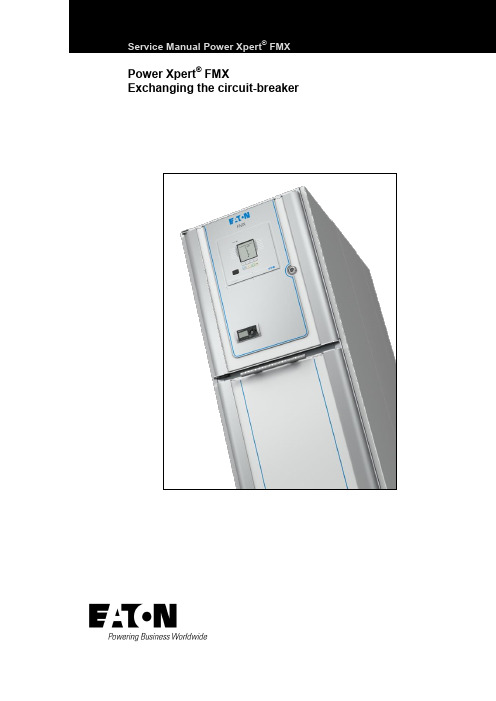
Service Manual Power Xpert® FMX Power Xpert® FMX Exchanging the circuit-breakerTable of contentsTable of contents1General 41.1Introduction 41.2Explanation of used warnings 41.3Safety relating to medium-voltage installations 41.4Tools, aids and protection equipment 51.5Product standards and guidelines used 51.6Product information 62FMX SYSTEM DESCRIPTION 82.1FMX System description 82.2Cross-section, single line diagram and list of functions 82.3Technical specifications, general 103EXCHANGING THE CIRCUIT-BREAKER 11 Appendix 1 – Contact values 21 Appendix 2 - Materials and tools 22Power Xpert® FMX 606.3768-02 8 April 2013 3General4 Power Xpert ®FMX 606.3768-02 8 April 2013 1General1.1IntroductionThe user must have authority to perform switchingoperations, which means being qualified in accordance with locally applicable guidelines, government legislation and in-house company regulations with respect to the operation of medium-voltage installations.Legal and other regulations and documents pertaining to accident prevention, personal safety and environmental protection must be observed."The service activities described in this Service Manual are the full responsibility of the user and/or the third party who perform these activities.Eaton assumes no responsibility with respect to these activities and shall not be liable for any costs, damages or losses whatsoever arising from or attributable to the service activities or to the use of this Service Manual by user and/or third party, including but not limited to loss of production, loss of profit or revenue, loss of use, claims of customers of user or for any other indirect or consequential damage or loss."Operations involving the repair of the switchgear unit are to be carried out by personnel of Eaton Industries (Netherlands) B.V. or by Eaton trained and certified personnel.Information with respect to these operations is, therefore, not included in this manual.1.2 Explanation of used warningsThe manual uses the following names and signs to highlight important (safety) information:This warning indicates that non-observance of the specified (safety) instructions COULD result in serious bodily injury or even death.NOTEThis note provides the user with additionalinformation. The user's attention is drawn to possible problems.TIPTips provide the user with suggestions and advice on how to make certain tasks easier or more convenient.1.3Safety relating to medium-voltage installationsOperations on medium-voltage installations can be life threatening if the necessary procedures are not observed.Always take suitable precautions before working on a medium-voltage installation..All personnel involved in operations carried out on, with or near electrical installations require to have been instructed on the safety requirements, safety rules and instructions applicable to the operation of the installation. Personnel must wear suitable clothing which fits the body closely. The person in charge of the operations must ensure that all requirements, regulations and instructions are complied with. The FMX unit has been designed to ensure that it exceeds applicable regulations.Furthermore, primary component enclosures are arc-resistant and interlocks have been fitted to prevent dangerous operations.Operations when the unit has been isolatedSwitching off prior to carrying out operations on an isolated system is subject to a number of essential requirements. 1. Switching off;2. Complete isolation;3. Protection from reactivation;4. Checking whether the unit is dead;5. Provide short-circuit proof protective earthing and avisible work-in-progress earth when needed.6. Provide protection with respect to active componentsin the vicinity. Safe layout of the work areaEnsure that access and escape routes are free at all times.Do not leave flammable materials in or near access and escape routes. Flammable materials must not be stored in areas which could be affected by arcs. In the event of a fireNever attempt to extinguish a fire on the switchgear unit before it is completely dead, this applies to both primary and secondary switchgear. Even if non-conducting extinguishing materials are used, electricity may pass through the extinguishing equipment. Never extinguish a fire on the unit with water. Prevent water from flowing into the unit. Keep well clear of the unit while the fire is being extinguished in the area around the unit.GeneralPower Xpert ®FMX 606.3768-02 8 April 2013 51.4Tools, aids and protection equipmentTools, aids and protection equipment must meet the requirements of national and international standards insofar as they are applicable. Drawings and documentsRecent documents of the electrical installation must be available in order to gain sufficient understanding of the schematic layout of the switchgear unit. Warning signsIf necessary, suitable warning signs shall be placed on the switchgear unit during operations to highlight possible hazards. The warning signs must comply with the applicable standards, insofar as they apply. Performing measurements safely on the unitSuitable and safe measuring equipment must be used for measuring safely on the unit. These instruments must be checked before and after use. The instruments must also be inspected periodically in accordance with the applicable regulations.1.5 Product standards and guidelines usedTable 1: Current product standards usedSwitchgear IEC Standard TitleGeneral62271-1 Common specifications for high-voltage switchgear and controlgear62271-200A.C. metal-enclosed switchgear and controlgear for rated voltages above 1 kV and up to and including 52 kV62271-201A.C. insulation-enclosed switchgear and controlgear for rated voltages above 1 kV and up to and including 38 kVDevices 62271-100 High-voltage alternating-current circuit-breakers62271-102Alternating current disconnectors and earthing switches50181Plug-in type bushings above 1kV up to 36kV and from 250A to 1.25kA for equipment other than liquid filled transformersDegrees of protection 60529 Degrees of protection provided by enclosures (IP Code)Voltage detection 61243-5 Live working - Voltage detectors - Part 5: Voltage detecting systems (VDS) Transformers 60044-1 Instrument transformers - Part 1: Current transformers60044-2 Instrument transformers - Part 2 : Inductive voltage transformers Communication 60870-5 Telecontrol equipment and systems. Part 5: Transmission protocols 61850Communications networks and systems in substations ISO ISO 9001-2000 QualityISO 14001 Environmental managementGeneral6 Power Xpert ®FMX 606.3768-02 8 April 2013 1.6Product informationThe unit is equipped with type plates on the inside walls of the secondary compartment The system nameplate includes: ∙ technical specifications;∙ serial number and year of manufacture.Each panel is uniquely identifiable by its panel nameplates.They are located on the left inside wall in the cable connection compartment of each panel. The panel type plate includes: ∙ the switch type;∙ technical specifications.Application outside the 'Normal Service Conditions' set out in IECPlease contact Eaton if the unit is used in anenvironment not in accordance with the 'Normal Service Conditions' in IEC 62271-1.Powering Business worldwideFig. 1-1: Example of system nameplateFig. 1-2: Example of panel type plate for circuit-breakerFig. 1-3: Current transformer information plateFig. 1-4: Voltage transformer Information plateGeneralTable 2: Explanation of type plate data in accordance with IECPower Xpert® FMX 606.3768-02 8 April 2013 7FMX SYSTEM DESCRIPTION8 Power Xpert ®FMX 606.3768-02 8 April 2013 2FMX SYSTEM DESCRIPTION2.1FMX System descriptionThe FMX switchgear system is a system with circuit-breakers which can be available for applications up to 24kV.The system is fully metal-enclosed. A very compact and safe implementation is achieved using high-quality epoxy resin insulation.Electric field strengths are kept at low levels by using specially shaped single-pole insulation components, as a result of which the risk of an internal fault is kept to an absolute minimum.All live primary components of the unit and the main components of the drive mechanisms are housed in a closed enclosure. This prevents any dust, moisture and other environmental factors from affecting the proper operation of the system.The enclosure is also arc resistant and thus provides conditions of optimum safety for the operator. The cable compartments are also available in arc-proof configuration.Two basic panel versions are available:∙ a vacuum circuit-breaker of 630, 800, 1250, 1600,2000 A.∙ a sectionaliser panel with vacuum circuit-breakers of1250, 1600, 2000 A.Both versions can be supplied in any combination and sequence in a system.The system has two compartments: one mainBusbar/Change-over switch compartment and a Circuit-breaker/Cable connection compartment.The main busbar system is on top of the panel and is completely closed. In the cable compartment are the current transformers and in the cable compartment voltage transformers can also be installed.The voltage transformers in the cable compartment are fully electrically operated from the front of the panel where the cable must be tested.Busbar voltage transformers are on the top of the system and also on top of the sectionalisers.Cables with a diameter up to 800 mm2 can be connected with T-connectors and cables for more than 1200 mm2, a flag connection is available.An interlocked cable connection point to test the cables is in the front of the panel.Earthing of the busbar is possible with the sectionaliser. It is also possible to make a circuit-breaker applicable for earthing the busbar. The circuit-breaker is equipped with vacuum interrupters and an electromagnetic mechanism, suitable for 30,000 operations.The circuit-breaker can be exchanged within 30 minutes from the front side of the panel.The change-over switch has two positions, connected to the busbar or connected to earth.The cable is earthed via the circuit-breaker.The interlock between the circuit-breaker and the door of the cable compartment is mechanical. The interlock between the circuit-breaker and the change-over switch is electric.The insulation of the busbar system is based on airinsulation. All other insulation is obtained by an insulating epoxy resin in which all single phase components are embedded and where the field strength between the conductors is controlled by the thickness and shape of the epoxy resin.2.2Cross-section, single line diagram and list of functionsFunctions circuit-breaker ∙ Connect cable to busbar. ∙ Disconnect cable.∙ Connect cable to earth.∙ Protect outgoing feeder from overcurrents. ∙Testing of the cable.Functions sectionaliser ∙ Connection of sections. ∙ Disconnection of sections. ∙ Earthing of sections.FMX SYSTEM DESCRIPTIONPower Xpert ®FMX 606.3768-02 8 April 2013 91. Busbar2. Secondary compartment3. Arc absorber4. Operating panel5. 2-position change-over switch6. EM-Mechanism7. Vacuum interrupter8. Cable test opening9. Cable connection 10. Voltage transformerFig. 2-1: Cross section circuit-breaker 630 / 800 A1. Busbar2. Secondary compartment3. Arc absorber4. Operating panel5. 2-position change-over switch6. EM-Mechanism7. Vacuum interrupter8. Cable test opening9. Cable connectionFig. 2-2: Cross section circuit-breaker 1250 / 1600 / 2000 A1. Busbar2. Secondary compartment3. Arc absorber4. Operating panel5. 2-position change-over switch6. EM-Mechanism7. Vacuum interrupterFig. 2-3:Cross section sectionaliser 1600 / 2000 AFMX SYSTEMDESCRIPTION2.3 Technical specifications, generalTable 3: Technical specifications* Per section one arc absorber box of 150 mm should be installed. With busbar voltage transformers the height is 500 mm more.10 Power Xpert® FMX 606.3768-02 8 April 2013 3 EXCHANGING THECIRCUIT-BREAKER Exchanging a vacuum circuit-breaker within the FMX switchgear may only be done by certified persons. Certified persons will only receive a certificate if they pass a special Eaton training. The certificate is valid for one year and only applicable for the trained person and organisation. Extension of the certificate can only be given by Eaton.Exchanging a circuit-breaker is only necessary in a very few occasions. Please consult the Eaton Service Organisation.Cables connected to the panel that needs an exchange of the circuit-breaker should be earthed on the opposite side!In case of a defect the circuit-breaker has to be exchanged and the complete system should be de-energized for a short period.Starting position of the Circuit-breaker see Fig. 3-1:∙Circuit-breaker ON.∙2-position change-over switch in Busbar position.Procedure:∙Switch OFF the circuit-breaker.∙Use the built-in voltage detector to check that the cable is dead in the outgoing panel.Arrows and dots are visible:∙Detector is functioning correctly and the cable is live.∙Arrows and dots not visible: cable is dead.NOTEThe visible dot shows that the detector is functioning correctly in accordance with the demands for voltage detecting systems as described in VDE 0682art. 415.This is a continuous internal function check.∙When the arrows and dots are not visible then check the operation of the voltage detection using thevoltage detection tester see Fig. 3-2:∙Insert the tester plugs in the contact sockets “earth” and L1. Test the detector by pressingthe tester button. The tested phase arrow anddot should now be present;∙Repeat the test for L2 and L3.∙If one or more arrows and dots do not appear, this might be the result of a faulty voltagedetector. Should this be the case contactEaton. Ensure by other means that the cable isdead before carrying out any further switchingoperations. Fig. 3-1 Fig. 3-2Fig. 3-3Power Xpert® FMX 606.3768-02 8 April 2013 1112 Power Xpert ®FMX 606.3768-02 8 April 2013 When the arrows and dots are visible then thefunctionality of the voltage detector can be tested as follows:∙ Connect a wire from the tester between thecontact sockets “earth” and L1. The arrow and dot indication from this phase must disappear. ∙ Repeat this test with the phases L2 and L3.NOTE The detector also has a piezo test button on the front for testing the LCD screen only.If the VDS system is functioning well but shows a “life” cable, switch off all incoming cables and earth these cables higher in the system.∙ Push OFF button for moving the 2-position change-over switch to the Earth position (Fig. 3-4).∙ Push ON button for Circuit-breaker ON. The cable isnow connected to earth.Fig. 3-4∙Open the top-unit and turn off the auxiliary voltage by switching the MCB's off (Fig. 3-5).Fig. 3-5∙Remove the strip, filoform covering plate and disconnect the low voltage terminals on clamps 1 up to 68 (X1) (Fig. 3-6).Fig. 3-6Power Xpert ®FMX 606.3768-02 8 April 2013 13∙Pull the Earth Lock and remove the cable door.Fig. 3-7∙Manually switch off the circuit-breaker.Fig. 3-8∙M ove the change-over selector switch to the left (Manual) position.Fig. 3-9∙Remove the 4 screws of the manual operation panel. Remove the Earth Lock and Manual Switch Off Handle.Fig. 3-10∙Push the Earth Lock support to the right.Fig. 3-1114 Power Xpert ®FMX 606.3768-02 8 April 2013 ∙Prove that all connection points (cable and change-over switch side) are dead. Do this by inserting a HV test probe into the holes and test the voltage to earth.Fig. 3-12∙ Remove the interlock of the cable compartment door (Fig. 3-13).∙Unscrew 5 captive bolts of the circuit-breaker. Leave the upper mid bolt connected. Forunscrewing the upper 2 bolts, turn the cover to open the openings (Fig. 3-14& Fig. 3-15).Fig. 3-13Fig. 3-14Fig. 3-15∙Place the truck. Make sure that the truck is placed in the right position (height) and that the brakes are activated (Fig. 3-16).Fig. 3-16Power Xpert ®FMX 606.3768-02 8 April 2013 15∙Unscrew the bolt on the backside of the Circuit-breaker (Fig. 3-17).Fig. 3-17∙Unscrew the last captive bolt (upper mid position) of the circuit-breaker (Fig. 3-18).Fig. 3-18∙Withdraw the circuit-breaker out of the panel.During withdraw make sure it is kept in a horizontal position. (Fig. 3-19)Fig. 3-19∙Remove the truck with circuit-breaker and change it by a second truck with a new circuit-breaker (Fig. 3-20).∙Place the second truck with the new circuit-breaker. Make sure it is placed in the right position (height) and that the brakes are activated (Fig. 3-21). ∙Then move the circuit-breaker into the panel.Fig. 3-20Fig. 3-2116 Power Xpert ®FMX 606.3768-02 8 April 2013 ∙Tighten the first bolt (upper mid position) before removing the truck! Tighten with a torque of 40 Nm (Fig. 3-22).Fig. 3-22∙Release the brake of the empty second truck and remove the truck (Fig. 3-23).Fig. 3-23∙Tighten the remaining 5 captive bolts. Tighten with 40 Nm. Check if the gray back plate of the mechanism hits the white plate of the housing (Fig. 3-24).Fig. 3-24∙Bring the secondary wiring with plugs back to the top-unit (Fig. 3-25).Fig. 3-25∙Tighten the bolt on the back side of the Circuit-breaker with a long tool (Fig. 3-26).Fig. 3-26Power Xpert ®FMX 606.3768-02 8 April 2013 17∙ Install the interlock of the cable compartment door (Fig. 3-27).∙Install the complete Manual Operation Panel. Make sure that the Change-over selector slide is in the manual position (left) (Fig. 3-28).Fig. 3-27Fig. 3-28∙Install the 4 screws of the manual operation panel. Install the Earth Lock and Manual Switch Off Handle (Fig. 3-29& Fig. 3-30).Fig. 3-29Fig. 3-30∙Lock the 2-position change-over switch by padlocking the selector in the mid position (Fig. 3-31).Fig. 3-31∙Turn on the auxiliary voltage by switching the MCB’s. Next close the top-unit door (Fig. 3-32).∙Switch on the circuit-breaker by pushing the push button on the top-unit door. The cable is nowearthed via the circuit-breaker (Fig. 3-33).∙Insert the test pins in the cable test facility holes (Fig. 3-34).∙Connect the test apparatus (Fig. 3-35):∙Connect the current injection cables to the earth bar and the backside of the test pin.∙Connect the voltage measurement cables to the earth bar and the backside of the test pin. ∙Switch off the circuit-breaker by pushing the push button on the top-unit door (Fig. 3-36). Fig. 3-32 Fig. 3-33 Fig. 3-34 Fig. 3-35 Fig. 3-3618 Power Xpert® FMX 606.3768-02 8 April 2013 ∙Inject 100A DC (I0) through the created circuit and measure the voltage U2 (mV) (Fig. 3-37).∙Calculate the resistance of the created circuit with following formula R2 = (U2/ I0) * 1000 (Fig. 3-38).∙Switch on the circuit-breaker by pushing the push button on the top-unit door (Fig. 3-39).∙Inject again 100A DC (I0) through the created circuits (in this case two circuits) and measure the voltage U2 (mV) (Fig. 3-40).∙Now calculate the current I2 (ADC) that runs through the cable plug with following formula:I2 = (U2 / R2) * 1000.∙Also calculate the current (I1) that runs through the circuit-breaker. This current can be calculated with following formula: I1 = I0 - I2(Fig. 3-41). Fig. 3-37 Fig. 3-38 Fig. 3-39 Fig. 3-40 Fig. 3-41Power Xpert® FMX 606.3768-02 8 April 2013 19∙Connect the voltage measurement cable to the earth bar of the 2-position change-over switch (Fig. 3-42).∙Inject again 100A DC (I0) through the created circuits (in this case two circuits) and measure thevoltage U1 (mV) (Fig. 3-43).∙Now calculate the resistance R1 of this circuit. This can be done with following formula:R1 = (U1 / I1) * 1000.∙Check if the calculated value is according the required value (see appendix for values per circuit-breaker type) (Fig. 3-44).∙If the values are ok, the breaker is built in correctly.∙Remove the test apparatus (Fig. 3-45).∙Install the filoform covering plate and strip.∙Remove the padlock on the 2-position selector switch.∙Remove the take-over earthing on the backside of the plugs.∙Install the cable door∙The panel is now ready for use again (Fig. 3-46). Fig. 3-42 Fig. 3-43 Fig. 3-44 Fig. 3-45 Fig. 3-4620 Power Xpert® FMX 606.3768-02 8 April 2013 Appendix 1 – Contact values630 A max. 160 mV 630 A max. 90 mV800 A max. 160 mV 800 A max. 90 mV1250 A * 1250 A *1600 A * 1600 A *2000 A * 2000 A ** Please contact Eaton for more information.Power Xpert® FMX 606.3768-02 8 April 2013 2122 Power Xpert ®FMX 606.3768-02 8 April 2013 Appendix 2 - Materials and toolsMaterials:∙ Scotch-Brite pads ∙ Silicon grease ∙ Acid free Vaseline ∙ BreakerTools:∙ Special long tool (green piece)∙Truck for replacing breaker∙Voltage test pinPower Xpert® FMX 606.3768-02 8 April 2013 23Eaton’s Electrical Sector is a global leader in power distribution, power quality, control and automation, and monitoring products. When combined with Eaton’s full-scale engineering services, these products provide customer-driven PowerChain™ solutions to serve the power system needs of the data center, industrial, institutional, public sector, utility, commercial, residential, IT, mission critical, alternative energy and OEM markets worldwide.PowerChain solutions help enterprisesachieve sustainable and competitiveadvantages through proactivemanagement of the power system as astrategic, integrated asset throughoutits life cycle, resulting in enhancedsafety, greater reliability and energyefficiency. For more information, visit/electrical.Eaton Industries (The Netherlands) B.V.P.O. Box 237550 AA HengeloThe NetherlandsTel.: +31 74 246 91 11Fax: +31 74 246 44 44***********************www.eaton.eu/electrical© 2013 Eaton CorporationAll rights reservedArt.no.: 606.3768-02。
伊顿 HD1 技术手册 (Ex d、Ex em 和 Ex ia) 说明书

Heat detector HD1Heat detector HD12 HD1 Heat Detector TM159 J October 2024 DISCLAIMER OF WARRANTIES AND LIMITATION OF LIABILITYThe information, recommendations, descriptions and safety notations in this document are based on Eaton Corporation’s (“Eaton”) experience and judgment and may not cover all contingencies. If further information is required, an Eaton sales office should be consulted. Sale of the product shown in this literature is subject to the terms and conditions outlined in appropriate Eaton selling policies or other contractual agreement between Eaton and the purchaser.THERE ARE NO UNDERSTANDINGS, AGREEMENTS, WARRANTIES, EXPRESSED OR IMPLIED, INCLUDING WARRANTIES OF FITNESS FOR A PARTICULAR PURPOSE OR MERCHANTABILITY, OTHER THAN THOSE SPECIFICALLY SET OUT IN ANY EXISTING CONTRACT BETWEEN THE PARTIES. ANY SUCH CONTRACT STATES THE ENTIREOBLIGATION OF EATON. THE CONTENTS OF THIS DOCUMENT SHALL NOT BECOME PART OF OR MODIFY ANY CONTRACT BETWEEN THE PARTIES.In no event will Eaton be responsible to the purchaser or user in contract, in tort (includingnegligence), strict liability or other-wise for any special, indirect, incidental or consequential damage or loss whatsoever, including but not limited to damage or loss of use of equipment, plant or power system, cost of capital, loss of power, additional expenses in the use of existing power facilities, or claims against the purchaser or user by its customers resulting from the use of the information, recommendations and descriptions contained herein. The information contained in this manual is subject to change without notice.Heat detector HD13 HD1 Heat Detector TM159 J October 2024 ContentsIntroduction............................................. 4 General safety messages and warnings........ 4 Installation.............................................. 4 General.................................................... 4 Removing/Replacing the cover............... 4 Operation......................................................... 5 Maintenance.................................................... 5 Certification / approvals................................... 6 Exd IIB Version.......................................... 6 Exd IIC Version.. (6)Ex em Version (6)Ex ia Version............................................. Special conditions of use………………………6 7Heat detector HD14 HD1 Heat Detector TM159 J October 2024 1.0 INTRODUCTIONThe HD1 heat detector has been designed for use in flammable atmospheres and harsh environmental conditions. The marine grade alloy (Exd) or Glass Reinforced Polyester (Exem and Exia versions) cover and enclosure are suitable for use offshore or onshore, where light weight combined with corrosion resistance and strength is required.2.0 GENERAL SAFETY MESSAGES AND WARNINGSAll instructions and safety messages in this manual must be followed to allow safe installation of the device. The device must only be installed and maintained by correctly trained site personnel/installers.i. To reduce the risk of ignition of hazardousatmospheres and shock, do not apply power to the device until installation has been completed and the device is fully sealed and secured. ii. To reduce the risk of ignition of hazardousatmospheres and shock, keep device tightly closed when the circuit is energised.iii. Before removing the cover for installation ormaintenance, ensure that the power to the device is isolated.iv. Following installation, test the device to ensurecorrect operation.v. Following installation ensure a copy of this manualis made available to all operating personnel. vi. When installing the device, requirements forselection, installation and operation should be referred to e.g. IEE Wiring Regulations and the National Electrical Code’ in North America.Additional national and/or local requirements may also apply.vii. Cable termination should be in accordance withspecification applying to the required application. MEDC recommends that all cables and cores should be correctly identified. Please refer to the wiring diagram in this manual (or separate diagram provided with the unit).viii. Ensure that only the correct listed or certified cableglands are used and that the assembly is shrouded and correctly earthed.ix. Ensure that only the correct listed or certifiedstopping plugs are used to blank off unused gland entry points and that the NEMA/IP rating of the unit is maintained.x. MEDC recommend the use of a sealing compoundsuch as HYLOMAR PL32 on the threads of all glands and stopping plugs in order to maintain the IP rating of the unit.xi. For the Exem and Exia versions, a suitable sealingwasher must be fitted to all glands and stopping plugs fitted into the enclosure.xii. The internal earth terminal, where fitted,must be used for the equipmentgrounding and the external terminal, if available, is for a supplementary bonding connection where local codes or authorities permit or require such a connection.xiii. When installing the device, MEDCrecommends the use of stainless steel fasteners. Ensure that all nuts, bolts and fixings are secure.xiv. Note: The purchaser should make themanufacturer aware of any externaleffects or aggressive substances that the equipment may be exposed to.xv. Potential electrostatic charging hazard,protect from direct airflow from exhaust ducts and the like which may cause charge transfer. If the unit requires cleaning, only clean the exterior with a damp cloth to avoid electrostatic charge build up. Ensure the equipment is correctly earthed.xvi. Installation shall be in accordance withIEC60079-14.3.0 INSTALLATIONGeneralThe heat detector is mounted via 4 off Ø9mm (Exd version) or 4 off Ø7mm (Exem and Exia versions) fixing holes in feet on the base of the unit.The fixing holes have been designed to accept M8(Exd version) or M6 (Exe/Exi versions) screws or bolts.The heat detector has been designed to operate in any attitude.Removing/replacing the Cove rExd version: Unscrew and remove the 4 off M6 screws (5mm A/F hexagon key required) and lift the cover clear of the base. The screws are not captive and should be kept in a safe place during cable termination.Exem/Exi versions: Unscrew the 4 off M5 screws (4mm A/F hexagon key required) and lift the cover clear of the base. The cover screws are captive and will be retained in the cover.Once cable termination has been completed, the cover can be replaced and secured to the enclosure. Ensure that any cover seal is correctly seated.On Exd versions ensure that the gap between the cover and enclosure is 0.15mm max. .Heat detector HD15 HD1 Heat Detector TM159 J October 2024 4.0 OPERATIONThe heat detector consists of a sealed element containing a single normally open (N.O.) thermal switch which operates at a fixed temperature. The operatingtemperature is stated on the identification label on the outside of the unit.The sensor element is fully sealed, and no attempt must be made to modify this in any way. Adjustment of the temperature setting is not possible.General arrangement (exd version)General arrangement (exe/exi versions)5.0 MAINTENANCEDuring the working life of the heat detector it should require little or no maintenance. However, if abnormal or unusual environmental conditions occur due toplant damage or accident etc., then visual inspection is recommended.If a fault should occur, then the unit can be repaired by MEDC.Under no circumstances should any attempt be made to either unscrew the heat detector element from the enclosure or gain access to the inside of the heat detector element.Either of these actions will result in the assembly becoming unsafe for use in potentially explosive atmospheres.If you have acquired a significant quantity of heat detectors, then it is recommended that spares are also made available. Please discuss your requirements with MEDC’s technical sales engineers.If the unit requires cleaning, only clean exterior with a damp cloth to avoid electro-static charge build up.Heat detector HD16 HD1 Heat Detector TM159 J October 2024 6.0 CERTIFICATION / APPROVALSExd IIB version: Certified toATEX: EN60079-0 , EN60079-1 , EN60079-31, IEC60079-33IECEx: IEC60079-0 , IEC60079-1 , IEC60079-31, IEC60079-33Ex d unit(ATEX certification No. Baseefa 03ATEX0447) (IEC certification No. IECEx SGS 24.0013X.)Ex db sb IIB+H2 T6 (Tamb -20°C to +55°C) Ex tb IIIC T85°C Db IP6x OrEx db sb IIB+H2 T3 (Tamb -20°C to +125°C)* Ex tb IIIC T200°C Db IP6x*Please refer to certification label for temperature ratingExd IIC version: Certified toATEX: EN 60079-0, EN 60079-1, EN60079-31, IEC60079-33IECEx: IEC60079-0 , IEC60079-1 , IEC60079-31, IEC60079-33Ex d unit(ATEX certification No.Baseefa08ATEX0320) (IEC certification No. IECEx SGS 24.0012X.)Ex db sb IIC T6 Gb (Tamb -20°C to +55°C) Ex tb IIIC T85°C Db IP6X OrEx db sb IIC T4 Gb (Tamb -20°C to +90°C) Ex tb IIIC T135°C Db IP6XFor Type HD1 Addressable Heat Detector Units which do contain an addressable module the marking remains as:Ex db sb IIC T6 Gb (Tamb -20°C to +55°C) Ex tb IIIC T85°C Db IP6XThe Exd ATEX certificate and product label carry the ATEX group and category marking:II 2 GD Where:Signifies compliance with ATEXII Signifies suitability for use in surface industries 2 Signifies suitability for use in a zone 1 areaG Signifies suitability for use in the presence of gases D Signifies suitability for use in the presence of dustThe IECEx certificate and product label carry the IECEx equipment protection level markingGb and Db where Gb signifies suitability for use in a Zone 1 surface industries area in the presence of gas.Db suitability for use in a Zone 21 surface industries area in the presence of dust.Exe version: Certified toATEX: EN60079-0 , EN60079-7, IEC60079-33 IECEx: IEC60079-0, IEC60079-7, IEC60079-33(ATEX certification No. Baseefa03ATEX0428) (IEC certification No. IECEx SGS 24.0035X) Ex eb sb IIC T6 Gb (-20°C to +55°C) (With resistors fitted)Ex eb mb sb IIC T4 Gb (-20°C to +55°C)The ATEX certificate and product label carry the ATEX group and category marking:II 2 G Where:Signifies compliance with ATEXII Signifies suitability for use in surface industries 2 Signifies suitability for use in a zone 1 areaG Signifies suitability for use in the presence of gasesThe IECEx certificate and product label carry the IECEx equipment protection level marking GbWhere Gb signifies suitability for use in a Zone 1 surface industries area in the presence of gas.Ex ia version:ATEX: Certified to EN60079-0 & EN60079-11 IECEx: Certified to IEC60079-0 & IEC60079-11(ATEX certification No. Baseefa03ATEX0427) (IEC certification No. IECEx BAS 13.0010)Ex ia IIC T6 Ga (-55°C to +55°C) - HD1I version Ex ia IIC T4 Ga (-55°C to +55°C) - HD1IR versionThe Ex ia ATEX certificate and product label carry the ATEX group and category marking:II 1 G Where:Signifies compliance with ATEXII Signifies suitability for use in surface industries 1 Signifies suitability for use in a zone 0 areaG Signifies suitability for use in the presence of gasesThe IECEx certificate and product label carry the IECEx equipment protection level marking Ga.Where Ga signifies suitability for use in a Zone 0 surface industries area in the presence of gas.Heat detector HD17 HD1 Heat Detector TM159 J October 2024 7.0 SPECIAL CONDITIONS OF USEExd IIB/IIC version:1. Cover screws of minimum grade A4-80stainless steel shall be used. 2. Warning – Potential electrostaticcharging hazard – See instructions.Exe version:For HD1R units only:1. The electrical supply to the encapsulatedResistor is limited to a maximum of 1.2W 2. Units fitted with the encapsulated resistorshall be protected by a fuse rated for a prospective short circuit current of at least 1500A .Heat detector HD18HD1 Heat Detector TM159 J October 2024 EatonEMEA Headquarters Route de la Longeraie 7 1110 Morges, Switzerland Eaton.euEatonUnit B, Sutton Parkway Oddicroft Lane Sutton in Ashfield United Kingdom NG17 5FBT: +44 (0) 1623 444 400 /hac*******************© 2024 EatonAll Rights Reserved Printed in September Publication No. TM159/J Changes to the products, to the information contained in this document, and to prices are reserved; so are errors and omissions. Only order confirmations and technical documentation by Eaton is binding. Photos and pictures also do not warrant a specific layout or functionality. Their use in whatever form is subject to prior approval by Eaton. The same applies to Trademarks (especially Eaton, Moeller, and Cutler-Hammer). The Terms and Conditions of Eaton apply, as referenced on Eaton Internet pages and Eaton order confirmations.Eaton is a registered trademark.All trademarks are property of their respective owners.。
伊顿并联混合动力系统参数设置

伊顿并联混合动力系统参数设置摘要:1.医联体医师诊疗奖惩制度的背景和意义2.医联体医师诊疗奖惩的具体措施3.医联体医师诊疗奖惩制度的实施效果4.医联体医师诊疗奖惩制度的存在问题和改进方向正文:一、医联体医师诊疗奖惩制度的背景和意义随着我国医疗体制改革的深入推进,医联体作为新型医疗服务体系的重要组成部分,逐渐成为实现分级诊疗、双向转诊、上下联动、急慢分治的重要途径。
在这个过程中,建立健全医联体医师诊疗奖惩制度,对于提高医疗服务质量、激励医师积极性和创造力具有重要意义。
二、医联体医师诊疗奖惩的具体措施1.建立绩效考核制度:通过制定科学合理的绩效考核指标,对医师的诊疗质量、服务效率、费用控制等方面进行量化评估,实现奖优罚劣。
2.设立奖励与惩罚措施:对于表现优异的医师,给予一定的物质和精神奖励,如奖金、晋升机会等;对于诊疗质量不高、服务态度恶劣的医师,给予相应的处罚,如扣发奖金、降低职称等。
3.完善培训与教育机制:加强对医师的业务培训和职业道德教育,提高其诊疗水平和服务素质,使其更好地适应医联体发展的需要。
三、医联体医师诊疗奖惩制度的实施效果医联体医师诊疗奖惩制度的实施,有助于提高医师的诊疗水平和服务质量,提升患者满意度,促进医联体良性发展。
同时,通过奖惩制度的激励和约束作用,引导医师合理使用医疗资源,降低医疗费用,提高医疗服务效率。
四、医联体医师诊疗奖惩制度的存在问题和改进方向1.考核指标不够科学合理,需要进一步完善,使之更加符合医疗实际和患者需求。
2.奖惩措施力度不够,对于部分医师来说,奖惩效果不明显。
需要加大对优秀医师的奖励力度,同时对不合格医师加大处罚力度。
3.培训教育机制不够完善,需要加强对医师的业务培训和职业道德教育,提高其综合素质。
总之,医联体医师诊疗奖惩制度在推动医联体发展、提高医疗服务质量等方面发挥了积极作用,但仍存在一些问题和不足。
ET1-24伊顿 (1)

当手车退出工作位置一定距离后,上下活门自动关闭并遮蔽住一次静触 头,见图3。同时由于上下活门不联动,在检修时可仅用挂锁锁定带电侧 的活门,对带电导体实现有效隔离,从而确保检修人员的安全。
其中, 为进线侧标识, 为出线侧标识, 为带电标识。
在未确定进线侧是否带电的情况下,禁止触及进线侧活门。
6.1
图4 母线隔室 1.1 母线隔室泄压盖板 2 分支母线 4 主母线 5 支持绝缘子 6 一次静触头盒
产品说明书 IB022008SC
2012年8月版
图6 继电器仪表室
装置在断路器隔室A和电缆终端联接室C内的加热器处于加热状态时,可 防止凝露的产生。但是,当断路器手车处于工作状态时,需及时切断加 热器电源,使其处于非加热状态。
图8 断路器手车在试验位置 在此位置,二次插头插接好,辅助回路接通,主回路仍未接通。
技术数据
开关柜主要技术数据见表1 表1 开关柜主要技术数据
序号 1 2 3 4 5 6
项目 额定电压 额定电流 额定短路开断电流 额定短路关合电流 4S热稳定电流(有效值) 外形尺寸
7
防护等级
单位 kV A kA kA kA mm
参数值
24
630
1250...1600...2000 2500...3150
手车 16
ET1-24开关柜所配手车根据用途不同,可分断路器手车、电压互感器手 车(PT车)、隔离手车等。相同规格的手车可实现百分之百的互换。手车 在柜内设有隔离/试验位置和工作位置(详见图7,图8,图9),每一位置均 设有定位装置,以保证联锁可靠,手车的操作必须按联锁防误操作程序 进行。手车采用的丝杆传动操动机构,设计合理、制造 精良、可有效确 保手车在推进推出时,动作轻巧、灵活、平稳。
美国伊顿EATON卡套接头
700M-I
90°弯曲过板接头公制铰接螺栓
90°ELBOW BULKHEAD FITTIN
GS
720B-I
英制铰接螺栓
7BC-GDK/S
7BD-GDK/S
8C
9C
9D
AC-RN
AD-RN
AC-RN
AD-RN
ACCG-OG/RADDG-OG/
METRIC BOLT
BLE
1CI-RN
1DI-RN
公制螺纹铰接接头
METRIC BANJ0
1CJ-RN
1DJ-RN
美制JIC74。锥密封
JIC74°CONE SEALINGJ
1CM-RN
1DM-RN
公制螺纹60°锥密封 或组合垫密封两用柱 端
METRIC THREAD 60 CONE
SEALING OR BONDED SEAL ST
7BC-GDK/S
5CM-RN
5DM-RN
钢垫密封英管压力表 接头
公制内螺纹柱端接头
BSP PRESSURE GAUGE CONN
WITH DKI SEALING RING
ECTOR
METRIC FEMALE STUD FITTINGS
6C-LN/RN 6D-LN/RN
直通过板接头
STRA IGHT BULKHEAD FITTINGS
NS
卡套螺母
RL
RS
卡套
XC-RN
EATONS顿管接头具有50多种不同的形式,可供各种不同应用场合的灵活选择,加上许多EATON伊顿功能管接头,如旋转接头,球阀,单向阀,截止阀,测压接头等 与管接头配合使用,可大大方便系统的配套,提高系统密封的可靠性?
伊顿 永华 接头样本 1
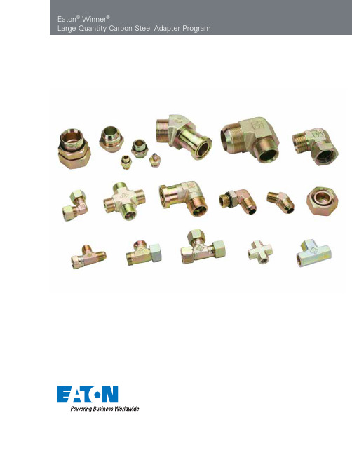
Eaton® Winner®Large Quantity Carbon Steel Adapter ProgramABCDEF2EATON Winner Carbon Steel Adapters E-MEAD-MC002-E April 2011Eaton® Winner®Carbon Steel Adapter Program Table of ContentsSection AJIC 74° (37°) Cone Flared Carbon Steel Adapters and SAE ORB Plugs 1J A-2 1J9 A-3 1JH A-3 1JN A-4 1JN4 A-5 1JN9 A-6 1JN9- A-7 1JN9- A-7 1JO A-8 1JO4-OG A-9 1JO9-OG A-10 1JO9-OG/ A-11 1JO- A-11 2J A-12 2J4 A-12 2J9 A-13 2NJ A-13 2OJ A-14 4ON A-14 4J A-15 4O A-15 5J A-16 5JN A-16 5JN9 A-17 5O A-17 6J-N A-18 6J4 A-18 6J9-N A-19 6NJ-N A-19 AJ A-20 AJ6JJ-N A-20 AJJ6J-N A-21 AJJN A-21 AJNJ A-22 AJJO-OG A-22 AJOJ-OG A-23 BJ A-23 CJ A-24 NB200 A-24 NB300 A-25 NB500 A-25Section BORFS Adapters1FN B-2 1FN9-16 B-2 1FO B-3 1FO4-OG B-3 1FO9-OG B-4 2F9 B-4 4F B-5 6F-L N B-56F9 B-69F B-6AFFO-OG B-7CF B-7Section CNPT Adapters1N C-21N9 C-24N C-34NN C-35N C-45N4 C-55N9 C-55ON C-65ON9-OG C-67N C-77N9-PK C-77NJ-S C-8GN-PK C-8HN C-9JN C-9ZN C-10Section DNPSM Adapters2NU D-22NU4 D-22NU9 D-32OU9-OG D-37NU-S D-4Section EFlange Adapters1JFL E-21JFL9 E-21JFS E-3Section FTechnical InformationWorking Pressure F-2Port Type and Dimensions F-4Recommended Thread Torque F-12Seal Specifications F-133EATON Winner Carbon Steel Adapters E-MEAD-MC002-E April 2011A B C D E FABCDEF4EATON Winner Carbon Steel Adapters E-MEAD-MC002-E April 2011JIC 74° (37°) Cone Flared Carbon Steel Adapters and SAE ORB PlugsPart No. IndexA-1EATON Winner Carbon Steel Adapters E-MEAD-MC002-E April 2011AEaton ®Winner ®JIC 74° (37°) Cone Flared Carbon Steel AdaptersThread Dimensions Part NumberEFAB L S11J-04Z 7/16"X207/16"X2014.014.03512Note: Nut and sleeve should be ordered separately. The nut NB200 and sleeve NB500 is suitable for metric tube, the nut NB200 and sleeve NB300 is suitable for inch tube.JIC Male 74° (37°) Cone1JA-2EATON Winner Carbon Steel Adapters E-MEAD-MC002-E April 2011AThread Dimensions Part NumberEFABS11J9-04Z 7/16"X20 7/16"X20 24.5 24.5 11Note: Nut and sleeve should be ordered separately. The nut NB200 and sleeve NB500 is suitable for metric tube, the nut NB200 and sleeve NB300 is suitable for inch tube.90° Elbow JIC Male 74° (37°) Cone1J91JHThread O-ring Dimensions Part Number EFF A BL S11JH-04-10Z 7/16”X20 M10X1O08.1X1.6 14 8.5 30 14Note: 1. Nut and sleeve should be ordered separately. The nut NB200 and sleeve NB500 is suitable for metric tube, the nut NB200 and sleeve NB300 is suitable for inch tube.2. F end is fit for ISO 9974-1 port or ISO 6149-1 port when useless of retaining ring.JIC Male 74° (37°) Cone / Metric Male Adjustable Stud End L-Series ISO 6149-31JHA-3EATON Winner Carbon Steel Adapters E-MEAD-MC002-E April 2011A1JNThread Dimensions Part Number EFAB L S11JN-04-02Z 7/16"X201/8"X27 14.0 10.5 30.5 12Note: Nut and sleeve should be ordered separately. The nut NB200 and sleeve NB500 is suitable for metric tube, the nut NB200 and sleeve NB300 is suitable for inch tube.JIC Male 74° (37°) Cone / NPT Male1JNA-4EATON Winner Carbon Steel Adapters E-MEAD-MC002-E April 2011A45° JIC Male 74° (37°) Cone / NPT Male1JN47Thread Dimensions Part No.EFAB S1A-5EATON Winner Carbon Steel Adapters E-MEAD-MC002-E April 2011A1JN9Thread Dimensions Part Number EFAB S11JN9-04Z 7/16"X201/4"X18 26.6 25.5 141JN9-32Z 2-1/2"X122"X11.5 75.4 67.5 63Nut and sleeve should be ordered separately. The nut NB200 and sleeve NB500 is suitable for metric tube, the nut NB200 and sleeve NB300 is suitable for inch tube.90° Elbow JIC Male 74° (37°) Cone / NPT Male1JN9A-6EATON Winner Carbon Steel Adapters E-MEAD-MC002-E April 2011A1JN9-LThread Dimensions Part Number EFAB S11JN9-04-02LZ 7/16”X20 1/8”X27 24.5 30 11Nut and sleeve should be ordered separately. The nut NB200 and sleeve NB500 is suitable for metric tube, the nut NB200 and sleeve NB300 is suitable for inch tube.90° JIC Male 74° (37°) Cone / Long NPT Male1JN9-L74°1JN9Thread Dimensions Part NumberEF AB S11JN9-04-02LLZ 7/16"X20 1/8"X27 24.5 39.6 11Nut and sleeve should be ordered separately. The nut NB200 and sleeve NB500 is suitable for metric tube, the nut NB200 and sleeve NB300 is suitable for inch tube.90° Elbow JIC Male 74° (37°) Cone / Longer NPT Male1JN9-LLA1JOThread O-Ring Dimensions 1JO-24-20Z 1-7/8”X121-5/8”X12O92027.515.0961.550Note: Nut and sleeve should be ordered separately. The nut NB200 and sleeve NB500 is suitable for metric tube, the nut NB200 and sleeve NB300 is suitable for inch tube.JIC Male 74° (37°) Cone /O-Ring Boss L-Series ISO 11926-31JOA1JO4-OGThread O-Ring Dimensions Part NumberEF FAB S1S21JO4-04OGZ 7/16”X20 7/16”X20O904 21 24.0 11 171JO4-20OGZ 1-5/8”X12 1-5/8”X12O920 42 48.5 41 50Note: 1. Nut and sleeve should be ordered separately. The nut NB200 and sleeve NB500 is suitable for metric tube, the nut NB200 and sleeve NB300 is suitable for inch tube. 2. F end is connected with ISO 11926-1 port.45° Elbow JIC Male 74° (37°) Cone / SAE O-ring Boss L-Series ISO 11926-31JO4-OG74°A1JO9-OGThread O-Ring Dimensions Part NumberEF FAB S1S21JO9-04OGZ 7/16"X20 7/16"X20 O904 24.5 27.2 11 1790° Elbow JIC Male 74° (37°) Cone / SAE O-ring Boss L-Series ISO 11926-31JO9-OGNote: 1 Nut and sleeve should be ordered separately. The nut NB200 and sleeve NB500 is suitable for metric tube, the nut NB200 and sleeve NB300 is suitable for inch tube. 2 F end is connected with ISO 11926-1 port.74ANote: 1. Nut and sleeve should be ordered separately. The nut NB200 and sleeve NB500 is suitable for metric tube, the nut NB200 and sleeve NB300 is suitable for inch tube. 2. F end is connected with ISO 11926-1 port.Thread O-Ring Dimensions Part Number EF FAB S1S21JO9-06OGLZ 9/16"X18 9/16"X18 O906 26.9 52.8 14 1990°JIC Male 74° (37°) Cone / Long SAE O-ring Boss L-Series ISO 11926-31JO9-OG/LNote: Nut and sleeve should be ordered separately. The nut NB200 and sleeve NB500 is suitable for metric tube, the nut NB200 and sleeve NB300 is suitable for inch tube.1JO-LThread O-Ring Dimensions Part Number EFFAB L S11JO-08LAZ 3/4"X163/4"X16 O908 48 11.1 67.5 22Long JIC Male 74° (37°) Cone / SAE O-ring Boss L-Series ISO 11926-31JO-LANote: Nut and sleeve should be ordered separately. The nut NB200 and sleeve NB500 is suitable for metric tube, the nut NB200 and sleeve NB300 is suitable for inch tube.2JThread Dimensions Part Number EFAB L S1S22J-08-10Z 3/4"X16 7/8"X14 16.7 13 36.5 22 27JIC Male 74° (37°) Cone / JIC Female 74° (37°) Seat2J74°2J4Thread Dimensions Part Number EFAB S1S22J4-04Z 7/16"X20 7/16"X20 21.5 911152J4-20Z 1-5/8"X121-5/8"X12 43.017 41 50Note: Nut and sleeve should be ordered separately. The nut NB200 and sleeve NB500 is suitable for metric tube, the nut NB200 and sleeve NB300 is suitable for inch tube.45° Elbow JIC Male 74° (37°) Cone / JIC Female 74° (37°) Seat2J4A2J9Thread Dimensions Part NumberEF AB S1S22J9-04Z 7/16"X20 7/16"X20 24.5 9111590° Elbow JIC Male 74° (37°) Cone / JIC Female 74° (37°) Seat2J9Note: Nut and sleeve should be ordered separately. The nut NB200 and sleeve NB500 is suitable for metric tube, the nut NB200 and sleeve NB300 is suitable for inch tube.2NJThread Dimensions Part Number EFAB L S1S22NJ-02-04Z 1/8"X27 7/16"X2010.5 9.024.512152NJ-20Z 1-1/4"X11.51-5/8"X12 26.517.0 56.0 46 50NPT Male / JIC Female 74° (37°) Seat2NJASAE O-ring Boss / JIC Female 74° (37°) Seat2OJ2OJ Thread O-Ring Dimensions Part No.EFE A B LS1S220J-16Z 1-5/16"X121-5/16"X12091615.116.038.538414ONThread O-RIng Dimensions Part Number E E AL S14ON-04Z 7/16"X20 09049.111.5 54ON-08Z 3/4"X16090811.114.3 8SAE O-ring Boss Hollow Hex Plug4ONA4JThread Dimensions Part Number EAL S14J-04Z 7/16"X2014.020124J-32Z 2-1/2"X1233.9 5265Note: Nut and sleeve should be ordered separately. The nut NB200 and sleeve NB500 is suitable for metric tube, the nut NB200 and sleeve NB300 is suitable for inch tube.4J4OThread O-Ring Dimensions Part Number E E AL S14O-04Z 7/16"X20 0904 9.1517.014SAE O-ring Boss Plug4OAThread Dimensions Part NumberEFAL S1B5J-04-06SZ 7/16"X20 9/16"X1814.024.619 9.8Note: Nut and sleeve should be ordered separately. The nut NB200 and sleeve NB500 is suitable for metric tube, the nut NB200 and sleeve NB300 is suitable for inch tube.JIC Male 74° (37°) Cone / JIC Female 74° (37°) Seat5J 5JSThread Dimensions Part NumberEFAL S15JN-04Z 7/16"X20 1/4"X1814.035.519Note: Nut and sleeve should be ordered separately. The nut NB200 and sleeve NB500 is suitable for metric tube, the nut NB200 and sleeve NB300 is suitable for inch tube.JIC Male 74° (37°) Cone / NPT Female5JNA5JN9Thread Dimensions Part Number EFAB S15JN9-04Z 7/16"X20 1/4"X1830.922.4 19Note: Nut and sleeve should be ordered separately. The nut NB200 and sleeve NB500 is suitable for metric tube, the nut NB200 and sleeve NB300 is suitable for inch tube.90° Elbow JIC Male 74° (37°) Cone / NPT Female5JN95OThread O-Ring Dimensions Part NumberEFE AB S15O-12-06Z 1-1/16"X129/16"X18O91215.0926.0325O-20-16Z 1-5/8"X121-5/16"X12 O92015.1 42.0 50SAE O-ring Boss L-SeriesISO 11926-3 / SAE Female ISO 11926-15OANote: “LN” in part number designates the adapter with lock nut. Nut and sleeve should be ordered separately. The nut NB200 and sleeve NB500 is suitable for metric tube, the nut NB200 and sleeve NB300 is suitable for inch tube.6J-LNThread Dimensions Part Number EFAB L S1S26J-04LNZ 7/16"X20 7/16"X2014.032.552.51717JIC Male 74° (37°) Cone Bulkhead6J-LN6J4Thread Dimensions Part Number EFAB S1S26J4-06LNZ 9/16”X189/16”X1823.042.414226J4-16LNZ 1-5/16”X121-5/16”X1237.865.0334145° JIC Male 74° (37°) Cone6J4ANote: “LN” in part number designates the adapter with lock nut. Nut and sleeve should be ordered separately. Nut and sleeve should be ordered separately. The nut NB200 and sleeve NB500 is suitable for metric tube, the nut NB200 and sleeve NB300 is suitable for inch tube.6J9Thread Dimensions Part NumberEF AB S1S26J9-04LNZ 7/16"X20 7/16"X20 24.5 40.4 11 176J9-16LNZ 1-5/16"X12 1-5/16"X1250.071.0 33 4190° JIC Male 74° (37°) Cone Bulkhead6J9-LN6NJThread Dimensions Part Number EFAB L S1S26NJ-04-06LNZ 1/4"X18 9/16"X18 15.0 32.5 55.5 22 226NJ-16LNZ 1"X11.5 1-5/16"X12 25.5 44.5 83.0 41 41Note: “LN” in part number designates the adapter with lock nut. Nut and sleeve should be ordered separately. Nut and sleeve should be ordered separately. The nut NB200 and sleeve NB500 is suitable for metric tube, the nut NB200 and sleeve NB300 is suitable for inch tube.NPT Male / JIC Male 74° (37°) Cone Bulkhead6NJ-LNANut and sleeve should be ordered separately. The nut NB200 and sleeve NB500 is suitable for metric tube, the nut NB200 and sleeve NB300 is suitable for inch tube.AJThread Dimensions Part Number EF GA BC S1AJ-04Z7/16"X20 7/16"X20 7/16"X20 24.5 24.5 24.511AJ-16Z 1-5/16"X121-5/16"X121-5/16"X12 49.0 49.0 49.0 33JIC Male 74° (37°) ConeAJNote: “LN” in part number designates the adapter with lock nut. Nut and sleeve should be ordered separately. The nut NB200 and sleeve NB500 is suitable for metric tube, the nut NB200 and sleeve NB300 is suitable for inch tube.AJ6JJThread Dimensions Part Number EF GA BC S1S2AJ6JJ-06LNZ9/16"X18 9/16"X18 9/16"X18 26.9 46.0 26.9 14 22JIC Male 74° (37°) ConeAJ6JJ-LNAThread Dimensions Part NumberEF GA BC S1S2Note: “LN” in part number designates the adapter with lock nut. Nut and sleeve should be ordered separately. The nut NB200 and sleeve NB500 is suitable for metric tube,the nut NB200 and sleeve NB300 is suitable for inch tube.JIC Male 74° (37°) ConeAJJ6J-LN74AJJNThread Dimensions Part Number EF GAB C S1AJJN-04Z 7/16"X20 7/16"X20 1/4"X18 26.6 26.6 25.514AJJN-16Z 1-5/16"X121-5/16"X12 1"X11.549.049.0 50.0 33Nut and sleeve should be ordered separately. The nut NB200 and sleeve NB500 is suitable for metric tube, the nut NB200 and sleeve NB300 is suitable for inch tube.JIC Male / JIC Male / NPT MaleAJJNAAJJO-OG Thread O-Ring Dimensions Part NumberEFG GA BC S1S2AJJO-04OGZ7/16"X20 7/16"X20 7/16"X20 O90424.5 24.5 27.21117Note: Nut and sleeve should be ordered separately. The nut NB200 and sleeve NB500 is suitable for metric tube, the nut NB200 and sleeve NB300 is suitable for inch tube.JIC Male / JICMale / SAE O-ring BossAJJO-OGJIC Male / NPT Male / JIC MaleAJNJ74°AJNJ Thread Dimensions Part No.EFGABCS1the nut NB200 and sleeve NB300 is suitable for inch tube.AAJOJ-OG Thread O-Ring Dimensions Part Number EF GF A BC S1S2AJOJ-06OGZ9/16"X18 9/16"X18 9/16"X18 O906 26.9 31.8 26.9 14 19Note: Nut and sleeve should be ordered separately. The nut NB200 and sleeve NB500 is suitable for metric tube, the nut NB200 and sleeve NB300 is suitable for inch tube.JIC Male / SAE O-ring Boss / JIC MaleAJOJ-OG74°BJThread Dimensions Part Number EF GA BC S1S2BJ-04Z7/16"X20 77/16"X20 7/16"X2024.5 924.51115BJ-20Z 1-5/8"X12 1-5/8"X12 1-5/8"X12 56.0 17 56.041 50Note: Nut and sleeve should be ordered separately. The nut NB200 and sleeve NB500 is suitable for metric tube, the nut NB200 and sleeve NB300 is suitable for inch tube.JIC Male / JIC Female / JIC MaleBJA74°CJCJ Thread DimensionsPart Number E F G A B C S1S2 CJ-04Z 7/16"X20 7/16"X20 7/16"X2024.524.5 9.01115CJ-20Z1-5/8"X121-5/8"X121-5/8"X12 55.5 55.51741 50 Note: Nut and sleeve should be ordered separately. The nut NB200 and sleeve NB500 is suitable for metric tube, the nut NB200 and sleeve NB300 is suitable for inch tube.JIC Male / JIC Male / JIC FemaleCJThread Tube O.D. & Sleeve Dimensions Part Number E in.Inch Sleeve mm Metric Sleeve L S2NB200-04Z 7/16"X20 1/4"NB300-046NB500-0615.814JIC Triple Lock NutNB200ANB300Tube Dimensions Part NumberThreadO.D.DLNB300-04Z 7/16"X201/4" 9.7310.4NB300-32Z 2-1/2"X122"61.1930.2JIC Inch SleeveNB300NB305TubeDimensions Part NumberThreadO.D. mm DLNB500-06Z 7/16”X2069.710.4NB500-32Z 1-5/8”X123238.923.1JIC Metric SleeveNB500APart No. Index Page intentionally left blank AORFS AdaptersPart No. Index1FNB-21FOB-31FO9-OGB-42F9B-44FB-56F-LNB-59FB-6AFFO-OGB-7CFB-71FN9-16B-21FO4-OGB-36F9B-6B Eaton® Winner®ORFS AdaptersORFS Male O-ring / NPT Male1FNThread O-Ring Dimensions Part Number EF EA BL S11FN-12Z 1-3/16"X12 3/4"X14 O018 17 19.5 49 32Thread O-Ring Dimensions Part NumberEFEA BS11FN9-16Z 1-7/16"X121"X11.5O02144.551.636Note: E end is connected with ISO 11926-1 port. ORFS fittings utilize a machined half dovetailed groove for seal retention.1FN9-1690° Elbow ORFS MaleO-ring / NPT MaleNote: ORFS fittings utilize a machined half dovetailed groove for seal retention.B1FO4-OGThread O-Ring Dimensions Part NumberEFEFA BL S11FO-04-06Z9/16"X18 9/16"X18 O011 O906 9.812.029.5 171FOORFS Male O-ring /SAE O-ring Boss S-Series ISO 11926-245° Elbow ORFS Male O-ring / SAE O-ring Boss S-Series ISO 11926-2Note: F end is connected with ISO 11926-1 port.ORFS fittings utilize a machined half dovetailed groove for seal retention.ThreadO-Ring Dimensions Part No.EFEFABS1S21FO4-04OGZ 9/16" X187/16" X20O011O90418.326.01417B1FO9-OG1FO9-OGThread O-Ring Dimensions Part NumberEFEF A BS1S21FO9-04OGZ9/16"X18 7/16"X20 O011 O904 23.030.3 14 171FO9-20OGZ 1-11/16”X121-5/8”X12O025O92047.560.54150Note: F end is connected with ISO 11926-1 port. ORFS fittings utilize a machined half dovetailed groove for seal retention.90° Elbow ORFS Male O-ring / SAE O-ring Boss S-Series ISO 11926-22F9Thread O-Ring Dimensions Part NumberEFE A BS1S22F9-06Z11/16"X16 11/16"X16 O012 27.5 10 19 222F9-16Z 1-7/16"X12 1-7/16"X12 O021 44.5 15 36 4190° Elbow ORFS Male O-ring / ORFS FemaleNote: ORFS fittings utilize a machined half dovetailed groove for seal retention.BORFS Male O-ring Plug4FThread O-Ring Dimensions Part NumberE E AL S14F-04Z 9/16"X18 O011 9.8 16.8 174F-20Z 1-11/16"X12 O025 17.5 27.9 466F-LNThread O-Ring Dimensions Part NumberEFEFA BL S1S26F-10LNZ1"X141"X14O016 O016 15.5 40.6 66.6 36 366F-20LNZ 1-11/16"X12 1-11/16"X12 O025 O025 17.5 42.2 70.2 50 50ORFS Male O-ring BulkheadLock NutNote: ORFS fittings utilize a machined half dovetailed groove for seal retention.Note: “LN” in part number designates the adapter with lock nut. ORFS fittings utilize a machined half dovetailed groove for seal retention.B。
伊顿液压接头样本

伊顿液压接头样本伊顿液压接头是一种高质量的接头产品,其品质和可靠性备受认可。
伊顿公司在液压系统领域拥有多年的经验,产品质量一直处于业界领先水平,大部分液压系统用户对其产品的表现都非常满意。
伊顿液压接头是由优质材料及精密制造工艺制成的,具有高强度、耐磨损、耐高温、抗韧性强等特点。
其设计紧凑,安装简便,使用寿命长,广泛应用于工程机械、风力发电、冶金、采矿、船舶、造纸、农业等领域,深受广大用户的好评。
伊顿液压接头有多种型号和规格可供选择,其尺寸和参数可根据用户的要求进行定制。
此外,伊顿还提供一系列优质的附件,使其产品的功能更为完善。
这些附件包括密封件、接头夹具、螺旋管等,其使用可以进一步提高伊顿液压接头的可靠性和稳定性。
伊顿液压接头的样本可以免费向用户提供,以方便用户在购买产品前进行实际测试和评估。
其样本包括螺纹式、卡箍式、冷压式等多种型号,同时还提供各种不同的材质选择,以满足各类液压系统用户的需求。
用户可以根据自己的实际需求和应用环境,选择最适合自己的伊顿液压接头产品。
伊顿液压接头的使用和维护非常简单,用户只需按照相应的操作步骤和注意事项进行操作和维护即可。
在使用时,用户需要注意液压系统的压力和温度范围,以免影响液压接头的使用寿命。
在维护时,用户需要定期检查液压接头的连接部位和密封件的状况,如发现问题需及时更换。
总之,伊顿液压接头是一种高质量、可靠性强、安装简便的接头产品。
其样本免费提供,用户可以在购买前进行实际测试和评估。
用户在使用伊顿液压接头时,需要注意压力和温度范围,定期维护以确保其长期稳定运行。
伊顿液压接头是液压系统领域中的优秀产品,值得用户的信赖和选择。
Eaton 电动汽车充电手册说明书

Handbuch zum Laden von ElektrofahrzeugenWarum sich für ein Elektroauto entscheiden? Elektrofahrzeuge: Die VorteileWelches sind die verschiedenen Arten vonE-Fahrzeugen und was ist deren Funktionsweise? Der Unterschied zwischen kWh und kWPHEV vs BEVElektrofahrzeug-Ladeinfrastruktur (EVCI) Stecker und Steckdosen für Elektrofahrzeuge Wie man ein Elektrofahrzeug auflädt FahrzeugkompatibilitätWo und wann man ein E-Fahrzeug auflädt Elektrofahrzeuge in der Energiewende Verzeichnis4 68 10 12 14 16 18 22 25 27 29Inhalt20152015100100%8080%6060%4040%2020%00Quelle: BloombergNEFQuelle: BloombergNEF Langfristiger weltweiter Pkw-Absatz nach AntriebsartAnteil am Jahresumsatz2020202020252025203020302035203520402040werden könnten.Verbrenner-Fahrzeuge Brennst-offzelle PHEV Ver-brenner-Fahrzeuge E-Fah-rzeugeE-FahrzeugeWelches sind die verschiedenen ArtenElektrofahrzeug (BEV)Es ist wichtig, zwischen den beiden gebräuchlichsten Abkürzungenim Zusammenhang mit dem Laden von Elektrofahrzeugen zuunterscheiden: Kilowattstunden (kWh) und Kilowatt (kW).Um zu berechnen, wie lange es dauert, ein Elektrofahrzeug vollaufzuladen, muss man sowohl die Kapazität (in kWh) der Batterie desFahrzeugs als auch die von der Ladestation angebotene Leistung(in kW) kennen.kWh und kWVerbrennungsmotor umschalten.6050403020100d u r c h s c h n i t t l i c he B a t t e r i e k a p a z i t ät (k W h )201420152016201720182019Quelle: Green MotionAutofahrer müssen ihre E-Fahrzeuge zu Hause und unterwegsaufladen können, was bedeutet, dass sie Zugang zu Ladepunktenin Wohngebieten und öffentlichen Einrichtungen wie Tankstellenund Arbeitsplätzen benötigen. Die Aufladung kann entweder mit AC(Wechselstrom) oder DC (Gleichstrom) erfolgen.AC LadetechnikDiese Art der Ladeinfrastruktur ist am günstigsten zu installieren, dader Wechselstrom direkt aus dem Netz kommt. Er kann einphasig (übereinen einzelnen Umrichter) oder dreiphasig (über drei Umrichter für einegrößere Leistungsübertragung) geführt werden. Im gewerblichen undindustriellen Bereich wird fast immer das dreiphasige System verwendet,da es eine effizientere Möglichkeit ist, höhere Ladeleistungen zu erzielen.Die Batterie in einem E-Fahrzeug arbeitet ebenso wie die Batterie ineinem Laptop oder Mobiltelefon mit Gleichstrom. Das bedeutet, dassder Strom von einem AC-Ladegerät von AC in DC umgewandelt werdenmuss, bevor er für die Stromversorgung der Fahrzeugbatterie verwendetwerden kann. Um dies zu ermöglichen, wird der Strom durch dasOnboard-Ladegerät (OBC) des E-Fahrzeugs geleitet, das die Spannungund den Strom reguliert. Die Ladegeschwindigkeit ist abhängig vonder Leistungsabgabe des OBCs. Das bedeutet, dass selbst wenn einElektrofahrzeug mit einem relativ leistungsstarken 22-kW-AC-Ladegerätgeladen wird, die Leistung, die die Batterie erhält - und damit auch,wie schnell sie ihre Kapazität erreicht - von den Kennwerten desOBC abhängt.DC LadetechnikGleichstrom-Ladung erfolgt in der Regel an speziellen Gleichstrom-Ladestationen außerhalb des Hauses, die eine höhere Leistung undschnellere Ladegeschwindigkeiten bieten. Bei der Gleichstromladungwird der Strom innerhalb der Ladestation umgewandelt und direkt zurBatterie geleitet, wobei der potenziell begrenzende OBC umgangenwird. Erste DC-Ladegeräte begannen bei etwa 50 kW, aber derLeistungsbereich der meisten ist jetzt von 20 kW auf mehr als 150 kWgestiegen, im Einklang mit der breiteren Verfügbarkeit von größerenBatteriekapazitäten für Elektrofahrzeuge. Die Verfügbarkeit von Gerätenmit 20 kW bedeutet, dass sich DC-Ladegeräte im Wohnbereichwahrscheinlich zunehmend durchsetzen werden. Außerdem bieten siedem Eigentümer die Möglichkeit, seine Einnahmen zu erhöhen, da dieKapazität der DC-Ladegeräte an Bord höher ist als die der AC-Ladegeräte. Elektrofahrzeug-Ladeinfrastruktur (EVCI)Wie man ein Elektrofahrzeug auflädtEs gibt verschiedene Arten von Ladesteckern für E-Fahrzeuge, jenachdem, ob sie an einen AC- oder DC-Ladepunkt angeschlossenwerden. Der Eingangsanschluss des Fahrzeugs und der Typ desLadegeräts bestimmen, welche Steckdose verwendet werden kann.Mode 1Haushaltssteckdose und Verlängerungskabel (AC)Dabei wird das Elektrofahrzeug über eine normale Haushaltssteckdoseund ein Kabel ohne Schutzeinrichtung an das Netz angeschlossen.Aufgrund des hohen Stromverbrauchs des Ladegeräts über mehrereStunden besteht eine erhöhte Wahrscheinlichkeit von Bränden oderelektrischen Verletzungen, daher wird Mode 1 nicht empfohlen.Mode 2Haushaltssteckdose mit kabelintegriertem FI-Schutzschalter (AC)Das Elektrofahrzeug wird über eine Haushaltssteckdose an dasStromnetz angeschlossen. Das Aufladen erfolgt jedoch über ein Kabelmit eingebautem Schutz (Fehlerstromschutzschalter oder RCD) zumSchutz vor elektrischen Schlägen und Bränden. (Es wird empfohlendie Steckdose bzw. den Anlagenteil der regelmäßig zum Laden vonElektrofahrzeugen verwendet wird, von einer Elektrofachkraft überprüfenzu lassen.)Mode 3Dediziertes EV-Ladesystem (AC)Ein E-Fahrzeug wird über eine spezielle Steckdose, einen Stecker undeinen eigenen Stromkreis an das Netz angeschlossen. Mode 3 kann imprivaten, gewerblichen und öffentlichen Bereich eingesetzt und je nachAnwendung mit unterschiedlichen Leistungen betrieben werden.Mode 4Dediziertes EV-Ladesystem (DC)Der einzige Modus für das DC-Laden, das über einen eigenen Stromkreisund einen Stecker und normalerweise nur an öffentlichen Ladestationenerfolgt. Die Umwandlung von Wechselstrom in Gleichstrom erfolgtinnerhalb der Ladestation, was eine Leistung von ca. 50 kW oder mehrermöglicht, wenn die Versorgung des Standorts dies zulässt.Wie man ein Elektrofahrzeug auflädt DaheimMehrfamilienhaus am ZielortArbeitsplatz UnterwegsMode 2Mode 3 Mode 3Mode 3Mode 3Mode 4Mode 4Mode 41–2 Std. (über Nacht)1–2 Std.(über Nacht)~8 Std.Angestellter~2 Std.Besucher1-2 Std.Besucher8 Std.Angestellte15-20 MinAC DCAC DC AC DCACElektrofahrzeug-Ladeinfrastruktur (EVCI)• Für einphasige 230-V-Anschlüsse, Leistung (kW) = Amp (A) x 230 V*0,001• Für 3-Phasen-400-V-Anschlüsse, Leistung (kW) = 1.732*Amp per Phase (A) x 400 V*0,001**je nach LandFahrzeugkompatibilität PHEVs und BEVs verfügen über sehr unterschiedliche Batteriegrößen, so dass ihre Ladeanforderungen und die Lademethoden, mit denen sie am besten kompatibel sind, unterschiedlich sind.Die Batterie von PHEVs ist kleiner, in der Regel zwischen 6-15 kWh, und der OBC ist im Allgemeinen auf 3,4 kW oder 7,4 kW begrenzt. Angesichts der Größe der mitgeführten Batterie ist Mode 2 am besten für das Laden im Haushalt geeignet, obwohl das schnellere Laden, das Mode 3 bietet, für Batterien am oberen Ende der PHEV-Skala,insbesondere für das Laden unterwegs, vorzuziehen sein könnte. BEVs besitzen größere Batterien, in der Regel von 30 kW bis hin zu 95 kWh für Hochleistungsfahrzeuge, wobei die OBCs von 7 kW bis 22 kW reichen. BEVs können Mode 1, 2 und 3 verwenden, wenn sie es wünschen, aber fast alle sind mit den speziellen Systemen und der zusätzlichen Leistung von Mode 4 kompatibel.Ein Tesla Model 3-Besitzer, der sein Fahrzeug an einer 22-kW-AC-Ladestation auflädt, erhält nur 11 kW, begrenzt durch das Onboard-Ladegerät des Fahrzeugs. Das Aufladen der Batterie dauert 5-7 Stunden. Bei Verwendung einer 50-kW-DC-Ladestation, deren DC-Ladeleistung 145 kW beträgt, gibt es keine Begrenzung und es dauert 40-60 Minuten, um die Batterie zu laden.T op 15 PHEVs und E-Fahrzeuge (bezogen auf den bisherigen Jahresabsatz) im Jahr 2020 in EuropaWo und wann man ein E-Fahrzeug auflädtDas Betanken von ICE-Fahrzeugen basiert auf dem Prinzip, zu tanken, wenn der Tank leer ist. Bei Elektrofahrzeugen sieht das ganz anders aus. Der Fokus muss sich auf das "Gelegenheitsladen" verlagern, bei dem das Laden anderen Aktivitäten, wie dem Einkaufen oder dem Gang zur Arbeit, untergeordnet ist. Das Ergebnis ist ein regelmäßiges Nachladen, um sicherzustellen, dass die Ladung des E-Fahrzeugs nie zu niedrig wird. Um diese Umstellung der Verhaltensmuster zu ermöglichen, wird ein dichtes Netz von Ladestationen stetig ausgebaut. Standorte für das Laden von Elektrofahrzeugen sind:Elektrofahrzeuge in der EnergiewendeElektrofahrzeuge in der EnergiewendeDie wachsende Zahl von E-Fahrzeugen und die entsprechendeInfrastruktur sind nur der Anfang der Mobilitätsrevolution. In derZukunft werden E-Fahrzeuge eine Schlüsselrolle bei der Unterstützungdes Übergangs zu einem Energiesystem spielen, das von variabler erneuerbarer Erzeugung dominiert wird. Bidirektionale Ladestationen fürE-Fahrzeuge ermöglichen es, dass E-Fahrzeugbatterien zur Stabilisierungdes Netzes beitragen, indem sie je nach Energieverfügbarkeit und -bedarf entweder als Stromspeicher oder als Stromquelle fungieren.Indem sie es ermöglichen, dass Energie vom Elektrofahrzeug zumGebäude (und damit zum Netz) fließt und nicht nur vom Gebäude zum Elektrofahrzeug, führen bidirektionale Ladegeräte ein enormes Maß an Flexibilität bei der Nutzung von Elektrofahrzeug-basierten Technologienein, die als V2X (Fahrzeug-zu-Allem), V2G (Fahrzeug-zu-Netz) und V2H (Fahrzeug-zu-Haus) bekannt sind. Dank dieser Technologien kann einE-Fahrzeug für viel mehr als nur für den Transport genutzt werden.Einige Beispiele:• Funktion als Notstromquelle bei Stromausfall• Beitrag zur Stabilisierung des Netzes durch Stromspeicher- und Versorgungsmöglichkeiten• Einnahmen durch den Verkauf von ungenutztem Strom an dasNetz erzielen• Kosteneinsparung durch Speicherung von Energie mit niedrigem Tarifzur Nutzung während der Spitzenlastzeiten• Speicherung von überschüssiger, selbst erzeugter erneuerbarerEnergie, um sie bei Bedarf zu nutzen (was sowohl zur Stabilisierungdes Netzes als auch zu Kosteneinsparungen beiträgt)VerzeichnisAC BEV CCS DCE-Fahr-zeuge EVCI HEVVerbrenner-FahrzeugekWkWhOBCPHEVRCDWechselstromBatteriebetriebenes Elektrofahrzeug (BEV)Kombiniertes LadesystemGleichstromElektrofahrzeugLadeinfrastruktur für ElektrofahrzeugeHybrid-ElektrofahrzeugVerbrenner-FahrzeugKilowattKilowattstundeOn-Board LadegerätPlug-in-HybridfahrzeugFehlerstrom-Schutzschalter(Residual Current Device)tiefreichendem regionalem praktischem Know-how in denBereichen Stromverteilung und Stromkreisschutz, Stromqualität, Notstromversorgung und Stromspeicher, Steuerung undAutomatisierung, Schutzschaltgeräten und Sicherheitsbeleuchtung, strukturelle Lösungen und Lösungen für raue und gefährliche Umgebungen.Durch End-to-End-Services, Vertriebskanäle, eine integrierte digitale Plattform und eine umfassende Kenntnis der Branche treibt Eaton branchenübergreifend und weltweit das voran, worauf es ankommt, und hilft Kunden bei der Lösungihrer kritischsten Herausforderungen im Bereich des elektrischen Energiemanagements.Eaton hat sich das Ziel gesetzt, durch den Einsatz seiner Energiemanagement-Technologien und -Dienstleistungen für mehr Lebensqualität zu sorgen und die Umwelt zu schützen. Die nachhaltigen Lösungen helfen den Kunden, elektrische, hydraulische und mechanische Energie sicherer, effizienter und zuverlässiger zu nutzen. Eaton erzielte im Jahr 2020 einen Umsatz von 17,9 Milliarden Dollar und verkauft Produkte in mehr als 175 Ländern. Weitere Informationen finden Sie unter .Wir behalten uns das Recht auf Änderungen an den Produkten oder den in diesem Dokument enthaltenen Informationen vor. Das gleiche gilt auch für Preise sowie jedwede Fehler und Auslassungen. Verbindlich sind nur die von Eaton erstellten Auftragsbestätigungen und technischen Dokumentationen. Auch Fotos und Abbildungen jeglicher Form sind keine Gewähr für die Gestaltung oderFunktionalität der Produkte. Deren Verwendung in jedweder Weise unterliegt der vorherigen Genehmigung durch Eaton. Dasselbe gilt für Marken (insbesondere Eaton, Moeller und Cutler-Hammer). Es gelten die Allgemeinen Geschäftsbedingungen von Eaton, wie auf denInternetseiten und den Auftragsbestätigungen von Eaton angegeben.Folgen Sie uns in den sozialen Medien und erhalten Sie aktuelle Produkt- und Supportinformationen.Eaton ist ein eingetragenes Markenzeichen.Alle anderen Warenzeichen sind Eigentum ihrer jeweiligen Inhaber.EatonEMEA Hauptverwaltung Route de la Longeraie 71110 Morges, Schweiz © 2021 EatonAlle Rechte vorbehaltenPublikationsnummer: BR191002DE Juni 2021。
- 1、下载文档前请自行甄别文档内容的完整性,平台不提供额外的编辑、内容补充、找答案等附加服务。
- 2、"仅部分预览"的文档,不可在线预览部分如存在完整性等问题,可反馈申请退款(可完整预览的文档不适用该条件!)。
- 3、如文档侵犯您的权益,请联系客服反馈,我们会尽快为您处理(人工客服工作时间:9:00-18:30)。
1) 电池冷却系统相关管路需尽量保证大的直径(进排气管路均不应小 于 2*ф60),较短的长度及较少的弯角,以保证整个系统尽量小的进 排气阻力;
2) 进气口应尽量位于车内较隐蔽地方,避免乘客无意把水或其它赃物 投入进气口;
要设计两根“Z”型用于将电池包固定于底盘骨架上。
z 电池包放置位置要求
4) 电池仓应远离热源,水源,避免外物轻易进入;
10
5) 电池仓应有良好的通风,避免处于密闭空间,影响散热; 6) 电池放置后应保证高低压接头可以方便插拔检查,红色服务开关容
易操作; 7) 电池放置后,电池滤清器必须保证容易更换 z 电池包支撑、固定骨架设计要求 电池包使用滑轨式安装,客车厂需自行设计滑轨,具体要求如下: 1) 两条轨道间的距离,平行度,平面度误差必须小于 0.5; 2) 轨道上平面(即电池安装平面)粗糙度小于 6.3; 3) 轨道平面须做防锈处理。
电机和逆变器之间需加装接地连接线,电机和逆变器有专用的凸台供安 装接地线。
6、自动离合器安装设计要求
混合动力所用的离合器为 365mm 拉式膜片弹簧单片离合器,由一个电 动执行机构(ECA)来完成分离与结合,许用的发动机扭矩为 900N.m,压盘 重量为 18.5Kg,从动盘重量约为 4.1Kg,离合器的轴向最大分离力为 2002N。 z 发动机飞轮接口要求
伊顿混合动力接口设计手册
(4 块电池系统)
版本号:Revision 1 日期:2009-8-20
1
目录
第一章 混合动力系统构成 1、系统构造示意图………………………………….…………(3) 2、系统元件示意图…………………………………….………(3) 3、混合动力系统元件清单………………………………………(4)
981.6mm
284.
334.
z 变速箱输入轴导向轴承:选用双面防尘免维护 6206 轴承(外径 62mm, 内径 30mm);
7
z 电机集成于变速箱和离合器的中间,为永磁同步电机,峰值功率 44KW, 持续功率 26KW,采用水冷方式,进出水口螺纹为 1.0625-12UN-2B,对 接螺栓高度不能大于 22mm,以免螺栓与电机内壁干涉。
1) 采用 SAE J1939 总线控制协议,详见相关的文件。 2) 发动机控制器应能够连续接受来自混合动力系统控制器的 TSC1 扭
矩控制命令,这意味着它不可在 TSC1 控制模式下中断接受混合动
6
力系统控制器的控制。 3) 发动机应能够被混合动力系统控制器通过总线命令关闭。 4) 发动机在 TSC1 控制模式下的扭矩控制误差应不超过±5%。 5) 当混合动力系统控制器在 TSC1 控制模式下要求发动机提供 0%扭矩
2、混合动力系统供电要求
混合动力控制系统要求使用独立的 12V 供电系统,具体要求如下: 1) 必须是完全独立的 12V 电系统,禁止此系统驱动整车其他元件; 2) 电瓶容量不小于 85Ah,且电瓶应避免放在发动机舱经受高温烘烤; 3) 供电电压为 11~14V,工作中瞬间电压不允许高于 16V。
3、混合动力系统线束设计要求
7、电池包总成安装设计要求
电池包总成包含有 4 块电池、电池管理系统、冷却风扇及通风管路、 连接线束、及相关金属件等构成,对外输出接口为:电池包的进排风、高 压电输出接头、低压控制线接头及应急切断开关,整个电池包的重量为 220Kg。
(样车电池包外观图)
(量产车电池包外观图)
对于样车电池包,需要加工一个进风罩来改造现行的进风口,同时需
混合动力系统需要有总线功能的仪表,对仪表的详细要求见单独的手册。
13
版次变更内容
1,2009 年 4 月 Revision 0 版本发行 2,2009 年 8 月 20 日 Revision 1 版本发行
变更内容:1、混合动力系统元件清单――增加部分零件的件号 2、混合动力冷却系统要求――变更冷却水泵的位置
9
6) 飞轮导向轴承内径与变速箱输入轴匹配,输入轴前端尺寸为:直径 φ=29.972~29.985mm(与 6206 的导向轴承相配)
z 发动机飞轮壳接口要求 1) 与 SAE#2 壳匹配 2) 飞轮后端面至飞轮壳后端面距离为 66.7mm 3) 在正对飞轮齿圈的位置钻一个螺纹孔,用于安装我们的传感器,传 感器的螺纹尺寸为:3/4-16 UNF-1A; 注:所用 Cummins 的飞轮为 FW9264,飞轮壳为 FH9490;
8
值会根据配置的发动机振动量不同而有所变化,客车厂负责评估这一数 值。
z 变速箱的润滑: 变速箱采用伊顿认证过的长效合成
润滑油――Synthetic CD50(油品供应商 科宁的编号为:Emgard 2979 SAE50),一台变速箱的用油量约为 10 升,以 润滑油与注油口平齐为准。 z 电机和逆变器之间的接地线
7 换挡操作说明标签 Shift Label
5586307
8 速度传感器 Speed Sensor
4306190
9 高压交流电缆 HV AC Cable
E-1050-741(2.2m) 量产号:5561951
10 高压直流电缆 HV DC Cable
E-1050-786(1.65m) 量产号:5561976
1) 9 个离合器安装孔分布于 393.7 圆周上(安装孔的螺纹大小应为 3/8 英寸);
2) 从飞轮的安装螺栓头端面到飞轮/离合器接触面至少需要 6.6mm 的 间距;
3) 飞轮镗孔为 180~184.25mm; 4) 飞轮上的离合器安装孔为英制“3/8-16 NC 2B” 5) 飞轮的直径大于 413.5mm
冷却系统的基本要求如下: 1) 冷却系统管路走向需保证先冷却逆变器,再冷却电机; 2) 逆变器入口前的液体温度不超过 60 ℃,电机入口前的液体温度不超
5
过 65 ℃,推荐中冷器的散热面积为 9m2 左右; 3) 散热器采用电子风扇冷却,此电子风扇受混合动力控制器控制; 4) 冷却水泵的流量为 20~27 升/分钟,压头为 0.3Bar(5.3~7gpm@4psi); 5) 冷却管路内径不小于 25mm,管路外边需要有编织层; 6) 系统需有膨胀水箱及液位显示装置; 7) 冷却液:只能采用 50/50 的乙二醇或 Dexcool 和水的混合液;
第二章 混合动力系统设计安装要求及各部件参数 1、 混合动力冷却系统要求…………………………………...…(5) 2、混合动力系统供电要求……………………………………….(6) 3、混合动力系统线束设计要求…………………………..……….(6) 4、对发动机的总线控制要求………………………………….….(6) 5、混合动力变速箱(内含集成的电机) 安装设计要求…………….….(7) 6、自动离合器安装设计要求………………………………….….(9) 7、电池包总成安装设计要求………………………………….….(10) 8、逆变器安装设计要求…………………………………..….….(11)
z 变速箱的安装角:应小于 6 度; z 变速箱的辅助支撑:
伊顿混合动力变速箱必须使用辅助支撑,支撑设计应和发动机支撑统一 考虑,尽量减小整个动力总成的震动。
z 离合器电动执行机构(ECA)保护板: 因 ECA 处于变速箱的最低位置,我们需要在它底部安装防撞梁,
考虑到发动机的上下振动量,保护梁距离 ECA 应大于 25mm,这一数
3) 排气口应布置于空气流通处,且避免竖直冲向地面,以免地面灰尘 倒吸入电池内部;
11
4) 每一出风口风量大于 1.4m^3/分钟;
8、逆变器安装设计
z 放置位置 1) 便于拆装维护; 2) 高低压接头便于插拔检测; 3) 放置空间需有较好的空气流通,便于散热; 4) 应远离热源,水源,并且需加保护,避免地面飞石损坏逆变器; 5) 高压接头处必须留有足够的接插空间(DC 接头为 300mm,AC 接头 200mm),避免高压线接头在连接时与车辆其他部件干涉。
时,发动机应能够维持稳定的怠速转速而不应有明显震动。 6) 发动机控制器应能够连续接受来自油门踏板的位置信号并在总线上
连续播送该信号。 7) 发动机控制器应能够连续接受来自制动踏板的制动开关信号并在总
线上连续播送该信号。
5、混合动力变速箱(内含集成的电机) 安装设计要求
z 输入扭矩:1166N.m;变速箱重量: 273Kg z 变速箱总长(从飞轮壳到输出拨叉结合面):981.6mm; z 变速箱各档速比:前进档位--7.05/4.13/2.52/1.59/1.00/0.78;倒档--6.75;
1) 线束设计需严格参照伊顿混合动力系统原理图; 2) 线束各接头必须选用伊顿指定的型号; 3) 线束线径规矩须严格遵守伊顿要求; 4) 线束设计需采用最高的防水规格,线束尽量全部采用全密封的波纹
管,如不行,可在一些最为重要的分支采用全密封波纹管。
4、对发动机的总线控制要求
需要采用匹配认证过的发动机,目前我们在国内匹配过的发动机有康明 斯的 ISBe185/220、ISBE4 205/225;东风康明斯的 ISDE230/245/270 系列; 玉柴的 YC6J200-30/YC6J210N-30。对发动机总线控制的基本要求如下:
14
z 安装方式 1) 直流高压接头禁止竖直向下; 2) 固定点必须有减震软垫。
12
第三章 混合动力系统对 ABS 和 仪表的要求
1、对 ABS 的要求
对于装有 ABS 系统的车辆,要求 ABS 按照 SAE J1939 的标准协议在 总线上发送信号,混合动力控制器将根据这一信号进行控制策略的调整。
2、对仪表的要求
2 电池盒(含 4 块电池) PEC (with 4 batteries) 3 逆变器 Inverter