【科龙空调维修】中央空调E系列单相电室外机(112和125)安装使用说明书
使用安装说明书OPERATINGANDINSTALLIN
请不要将空调器电源插头与其它自发供电设备连接。 如果连接将可能造成空调器损坏。
警告 如果处置错误,造成死亡、重伤结果或财产损 失的可能性很大。 注意 如果处置错误,可能造成空调机不能正常使用或造成损失。
安装结束后,请安装人员务必在安装结算联和保 修卡上按要求贴好条形码。
非常感谢您选用三菱电机房间空调器。 ·为了确保正确安全地使用本机,在使用前,请一定先阅读说明书。阅读以后请妥善保 存,以备必要时查阅。 ·购买机器时,须在出售店收取记载有「购买日期·店名」的有效证明。 ·顾客请不要自己安装机器(自行安装,将不能保证安全和功能,由此引起的安全问题 本公司不予负责。自行安装机器的售后服务不属于三包范围)。
安装位置安装在左面安装在中间检测范围图示传感器检测方向右面中间请查阅第4页说明遥控器电池盒内滑动开关设定这个测温方向设定是有记忆的前次设定状态这个全方位测温传感器在150的范围内三种安装空间之一左面中间右面检测地面墙面的辐射温度因此检测到的温度可能会不同由于标准温度接近于市售温度计所测值是依靠接近房间或接近地面或墙面的温度来分类
文中所用“图符号”的意思如下
:绝对不可做。 :一定请按指示做。 :禁止插进指头或棒条等。 :禁止踩到室内/室外机组上面或在它们上面堆放东西。
:有触电的危险请小心。 :一定请拔下电源线插头。 :一定请关闭电源。 :一定要接地线。
·阅读后,请收藏在使用者容易发现的地方,以便参考。 ·儿童或虚弱者必须在监护人协助下才可使用本空调器。
配 管 排水软管
排风口
排水口
3
各部件名称
遥控器
信号发射部
如何安装电池及设定当前时间
1 移去前盖,装入电池。重新装好前盖板。 先插入电池的负极。检查电池的极性是否正确。
(整理)第二部分:家用空调电源线、连机线安装规范操作指导手册-4-28
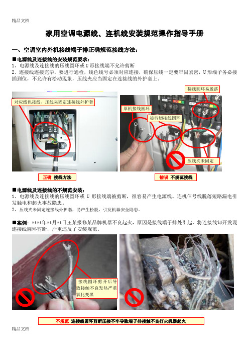
家用空调电源线、连机线安装规范操作指导手册一、空调室内外机接线端子排正确规范接线方法:■电源线及连接线的安装规范要求:1、电源线及连接线的压线圆环或U形接线端不允许剪断2、连接线连接完毕,要进行通检,线色线号必须对应连接,确保压线一定要牢固紧密,U形端子务必接插到位,不允许有松动现象,压线夹应当固定在连接线的外护套上。
■电源线及连接线的不规范安装:1、电源线及连接线的压线圆环或U形接线端被剪断,很容易产生电源线、连机信号线脱落短路漏电引发触电和起火事故隐患。
2、压线夹未固定连接线外护套,易产生松脱,引发机器安全隐患。
■案例:****年**月**日王某报修某品牌机器不良起火,原因是接线端子排处引起,将连接线卸开发现连接线圆环剪断,严重违反了安装规范。
二、用户家电源插座电流容量小提供大功率空调供电导致过热、过电流引起火灾:■正确规范安装:大功率空调器(一般是指制冷量在4500W以上的机器)应设专用供电线路和安装专用电源空气开关、漏电保护器;1、用户安装空调器的电源插座,必须带有接地线且电源插座的接地线连接牢固,插座的电流容量、结构和插孔尺寸应满足与待装空调器的电源插头相匹配2、2匹以上(或4500W制冷量以上,空调单相电源电源插头电流容量超过)的空调安装国家标准:GB17790-2008,或产品说明书的规定要求,对空调器的电源线路安装专用空气开关或漏电保护器。
■不规范安装:1、大功率柜式空调器的电源供电方式,采用电源插头供电因电流容量小,很容易造成电源插头与插座过电流、发热、电源短路引起火灾事故。
■案例:****年**月**日王某报修某品牌柜机空调器因电源插头与插座短路引起家中起火。
三、电源线或连机信号线加长线规范操作工艺:■加长电源线、连机信号线(电源开关)材料选用与规范操作要求:1、电源线或连机信号线加长时,应按照国标GB4706.32标准中规定,使用或选择空调随机出厂配置的电源线或连机信号线。
海信科龙空调安装规范

5、抽真空、检漏:
1)空调器的室内、室外机连接好后,针对新冷媒 (R410A)空调必须使用抽真空的方法来排除室内 机组的空气,排除系统管道中的空气。
2)空调器室内、室外机连接后打开粗、细截止阀 阀芯,制冷剂已经充满制冷管路,为保证制冷系统 能长期可靠的正常工作,必须对所有的管路接头、 阀门及螺母进行检漏。
4)柜机室内机安装位置以进出风不受阻挡为原则,侧面 出风的机型必须出风能顺利送达需降温的人或设备。
2.室外机位置选择:
1) 室外机组应不占用公共人行道,沿道路两侧建筑 物安装距地面距离应大于2.5m;室外机产生的噪音 和气流、外机漏水不影响到邻居的位置,儿童不易 触及的地方。 2)外机位置要考虑通风良好,维修方便,空间位置 最基本要求:左边 ≥50cm,右边 ≥60cm,后面 ≥30cm,上面 ≥30cm,前面 ≥200cm。 3)尽量选择避雨和不被阳光直接照射的位置安装, 避开自然条件恶劣(如油烟重、风沙大、阳光直射 或有高温热源)的位置。 4)室外机重量较大,所以要特别注意墙体是否牢固。 注意:当安装在受限空间内(格栅)时,室外机在 保证固定可靠的前提下尽量靠近前面格栅,并优先 保证左侧距离。
海信科龙空调安装要求及规范
空调顾客服务部技术培训室
目录
一、安装前的准备与检查 1)用户电源检查 2)内、外机外观及电功能检查
二、安装位置的选择 1)内机位置选择 2)外机位置选择
三、安装步骤 1)内机安装 2)外机安装 3)联管、联线操作要求 4)抽真空、检漏操作 5)特殊加长线、加长管的要求
四、试机
1)室外机与室内机连管长度, 一般距离不要超过5米, 最长不要超过10米。 2)壁挂机联管超过5米时,每超过1米,需补充加氟15g, 柜机联管超过7米时,每超过1米,需补充加氟40g。 3)联机管加长,加长后焊点一定要确认焊接牢靠,焊 点饱满。 4)室内机与室外机之间的高度差一般不超过5米, 要 尽量使室外机安装位置水平或者低于室内机安装位置. 以利于制冷剂和冷冻油良性循环. 。 5)变频空调内外机联机线不允许有加长,必须使用符 合国标的整根线替代。
科龙安装技术手册
左右风向按键 此机型无此功能
上下风向按键
按下此键,导风板上下摆动送 风,再按一下,锁定当前送风角度。
室外清洁按键 按下此键5秒后,进入室外自动清洁 功能。( 室外清洁期间,空调器 不响应遥控器和应急按键操作。)
风 下 上
风量 左右风
自 制除 动 冷湿
送制 风热
强睡 定 力眠 时
室外清洁 净化 室内清洁
广东科龙空调器有限公司
GUANGDONG KELON AIR CONDITIONER CO., LTD.
安装事项
1. 注意 A.用 户购 机 后 , 请 务 必 与 就 近 的 本 公 司 特 许 服务网点(以下简称“特许点”)联系安 装事宜,切不可自行安装或另请他人安装(不含窗机),以免发生意外或造成空调 器损坏。 B .非 “ 特 许 点 ” 安 装 的 空 调 器 , 本 公 司 将 不 负 责 免 费 维 修 。
在定时模式下,可设置定时开 机或定时关机,定时范围为0.5 ~24 小时。
睡 眠 定时 一键通
强力按键 在制冷、除湿、送风方式下 设定强力运行,室内风速为高风 速;在制热方式下设定强力运行, 遥控器显示风速为自动风速。 送风方式下设定强力运行, 空调器转入制冷方式。 强力运行持续时间最长为 15分钟。
号、购买日期等事项通知本公司顾客服务部,可补发新保修卡。
1
目录
空调安装说明书
空调安装说明书空调安装说明书篇一:空调使用说明书中央空调格力送风机组自动控制使用说明书为保证空调机组高效,节能,安全的运行。
请必须按照产品使用说明书运行。
1. 启动风机前a. 请将系统各电源,主控制断路器保持通路状态(此时主控制柜电源指示灯亮起,控制触摸屏电源灯亮起,触摸屏亮起)b. 应检查各个送风机组手动新风阀,送风防火阀是否处于开启状态,如未开启,请手动将阀门打开。
c. 送风机系统有电加热辅助加热系统,冬季运行时应保持电加热器常开状态(注,电加热器内有温控开关,当温度达到指定热量时,加热器会自动关闭加热系统,当温度低于设定温度时,加热器会自动开启)2. 手动启动a. 在控制屏上点击要启动的机组编号,如要启动1#机组,就触摸1#机组按钮,同理2#和3#。
此时控制屏上显示1#机组控制画面b. 在控制屏上点击手动启动/自动启动按钮,将显示状态改成手动启动状态。
此时空调系统进入手动启动模式。
c. 在控制屏上点击新风阀开启按钮,将新风阀打开,此时控制屏上显示新风阀打开。
d. 在控制屏上点击预热阀按钮,将预热阀状态改为开启状态,预热阀开启需要几秒中的时间间隔,(注机组开启时,预热阀必须是开启的,否者可能会严重损坏机组)e. 在控制屏上点击加热阀按钮,将加热阀状态改为开启状态,加热阀开启需要几秒中的时间间隔,(注机组开启时,加热阀必须是开启的,否者可能会严重损坏机组)f. 启动风机,点击风机启动按钮,将启动状态栏状态改为启动状态,此时风机启动。
3. 自动启动a. 在控制屏上点击对应要启动风机编号,此时屏幕上显示要启动风机控制版面。
b. 在控制屏上点击手动控制/自动控制一栏,点击自动控制按钮。
此时机组进入自动控制状态。
c. 在控制屏上点击自动启动按钮,此时机组自动启动(注,自动启动顺序,新风阀开启—预热阀开启—加热阀开启—风机启动)4. 注意事项a. 此空调设备具有恒温功能,当机组温度达到要求时,机组会相应动作,关闭机组预热阀,减少机组供热量。
中央空调安装流程和说明

一、安装位置第一次确定,由业主,空调设计师,空调现场施工负责人,装潢设计师都到现场商讨确认。
二、由本公司出具图纸交付装潢设计师做初步确认,确认完毕后交付业主签字,然后进场施工。
(无业主签字图纸不施工)三、空调设备进场,客户验收后空调内机拆封吊装上顶,给予客户和装潢负责人一个比较形象的概念,再次确定内机安装位置并同时确定空调遥控器在墙体上的位置。
此时如需要更改为免费服务,但需签定工程变更单(一)。
四、内机确认完毕后开始排空调管道,包括水管、冷媒管和线管等。
管道排装完毕后,需要更改的,如为小幅度更改(不修改主铜管位置或系统未做气密性实验)为免费服务,但客户需签定工程变更单(一),确认完毕再进行更改。
如修改幅度较大则直接填写工程变更单(二),并需收取相关成本费用。
五、管道排装完毕后,系统做气密性实验,确保系统无泄漏。
装潢公司开始按照本公司要求排装电源线至内外机位置和浇筑外机水泥台座,等到龙骨出来之后,本公司人员安装风管(高分子材料)和现试调试(补充冷媒安装室外机),并现场精确测量风口尺寸。
六、调试完毕后既确定设备系统完好,客户需现场鉴定后签定调试报告书。
等石膏板封好之后,本公司人员安装风口,并做系统最后一步调试交付业主。
如最后一步调试测出系统泄漏或其他问题则为非本公司安装问题,本公司承担维修责任,不承担其相关费用。
备注:1、凡需要客户至现场认定签字的情况,若业主委托其他责任人或者自己逾期未能签字的,既认定业主对已经完工工程事实认可。
2、工程变更单需要在工程修改前至业主和本公司经理(设计师)签字方可进行,大幅度修改填写变更单(二)并收取费用。
双方责任1、甲方责任1.1甲方指定安装位置及要求,提供乙方施工材料存放用地,施工用水、电,包括清除障碍物。
1.2甲方负责提供电源到乙方指定位置(室内、外机器旁边)。
LMX、家用VRV外机6平方线,220V,内机2.5平方,220VVRVⅢ外机大金要求为一匹一平方线,380V,内机2.5 平方,220V进行机器调试工作(临时电不调试),确保机器正常运行。
单元式空调机安装使用说明书
目录警告 ---------------------------1管路清洗----------------------------15前言 ---------------------------1蒸汽盘管或热水盘管------------------15潜在危险 -----------------------1排水管安装--------------------------15手册更新 -----------------------1电气接线----------------------------16安全警示 -----------------------1第三部份机组运行第一部份机组简介常用工具---------------------------19产品简介---------------------------3 机组运行管理-----------------------19机组外观图及结构图-----------------3 电源、仪器仪表检查-----------------19型号表示方法-----------------------4 制冷系统检查-----------------------19主要技术参数-----------------------5 水系统检查-------------------------19 第二部份机组安装机组日常运行检查-------------------20机组验货---------------------------6 机组运行---------------------------21 机组存放---------------------------6 第四部份机组维护保养机组搬运、吊装---------------------6 维护保养---------------------------24 机组定位---------------------------7 简易故障处理-----------------------24 安装空间---------------------------7机组安装---------------------------8机组连接---------------------------8循环水注意事项--------------------14警告所有的机组维护工作必须按本公司的安装使用说明书进行操作。
中央空调安装规范-附图(修)
中央空调装置规范和工艺之答禄夫天创作1. 通风与空调系统的组成:通风和空调工程包括(送排风系统、防排烟系统、防尘系统、空调系统、净化空气系统、制冷设备系统、空调水系统等七个子分部工程).2. 中央空调系统的组成:中央空调系统主要由制冷制热设备或装置(压缩机、压缩冷凝机组、冷水机组、空调箱、锅炉、喷水室等)、管路(制冷剂管路、冷媒管路、载冷剂管路等)、室内末端设备(室内风管水管、散流器、风机盘管、空调室内机等)、室外设备(室外风管、冷却塔、风冷式冷凝器等)、水泵、控制装置及附属设备等组成.3. 中央空调系统的分类:中央空调系统主要按如下方式分类:(1)按空气处置设备的集中水平分(2)按承当负荷的介质来分(3)按空调系统的用途分(4)按对建筑物内空气来源分其他的分类方法有:按风量是否固定分:定风量系统、变风量系统按风管内空气流速分:低速系统(<8m/s)、高速系统( >20~30m/s )按用途分:工艺性空调、舒适性空调按系统精度分:一般性空调、恒温恒湿空调按运行时间分:全年性空调、季节性空调按使用场所分:年夜型工民建筑用空调、商用空调、户式空调4.变流量系统(VRV)变制冷剂流量的VRV空调系统, 实质上是由制冷压缩机、冷凝器、电子膨胀阀、蒸发器、其他阀门和管路构成的环状管网系统.变流量系统组成变流量系统一般分为以下几种:(1)由室外机和多个室内机组成, 室外机由压缩机、外侧换热器和其他制冷附件组成, 室内机由风机、室内侧换热器组成;(2)制冷剂管路连接室外机和室内机, 长度可达50~125m, 落差可达30~50m;(3)智能控制系统可进行独自控制或分区集中控制.变流量系统特点(1)优点:各房间可以自力调节温度, 且控制精确, 变流量调节能效比力高.(2)缺点:控制系统复杂, 制冷剂管路较长易泄漏, 对管材、制造装置工艺要求高;机组存在回油、回液等技术问题.5.中央空调的装置规范中央空调历来就有“三分质量, 七分装置”的说法, 不论是工程项目还是别墅家装, 如果中央空调的装置分歧格那么后续会带来很多的麻烦, 今天给年夜家讲讲中央空调装置验收标准, 希望能给年夜家带来更多的帮手.VRV系统装置施工工艺及法式:1、确定施工范围2、熟悉施工图3、预埋套管4、装置室内机5、冷媒管装置6、保温施工7、室外机基础施工8、装置室外机9、气密性试验10、真空干燥11、灌注冷媒12、交付使用说明书1、管道和预埋件作业:1)冷凝管道预留孔应使管道具有向下的坡度(排水坡度至少坚持在i≥, 同时也必需考虑绝热管的厚度).2)冷媒管的通孔直径应考虑绝热资料的厚度(最好气管和液管双排并列).3)通风管道的通孔(方孔或圆孔)直径(根据全热交换器风量选择)2、室内机装置:把持步伐:测定装置位置→标识装置位置→装置悬吊支架装置室内机(1)关于室内机装置的说明所有设备的规格、型号、技术参数应符合设计要求和产物性能指标.①室内机设备的搬运和吊装:设备的搬运和吊装必需符合产物说明书的有关规定, 并应做好设备的呵护工作,防止因搬运或吊装而造成设备损伤. 吊装完成后的室内机做好防尘处置(用塑料进行包裹)环绕气流嵌入式天花板内藏风管式②室内机宜采纳弹性减震吊环吊装, 室内机下垫橡胶减震两层.③室内机位置应充沛考虑如下因素a、装置空间的高度确定. b、室内气流组织问题. c、吊顶内空调机的装置空间确定.d、空调与室内吊顶造型与灯具等的协调. e、要求室内机水平装置.(水平度在±2mm之内)要点:①悬吊支架必需足以接受室内机的运行重量;②装置前必需检查并核对设备型号, 并将检查情况填入设备开箱检查记录表.③注意校正主要的设备(主要是管道的安插和走向);④应留有足够的空间以供综合维修用, 尺寸为不小于450×450mm;⑤装室内机时应保证有足够的冷凝水管位置, 新风管位置(远离室内机接线端)(2)、支、吊架制作技术要求1)管道支、吊架、支座的制作依照图样要求进行施工;2)安插统一加工, 形式一致;3)型钢采纳机械下料, 不得采纳气(电)焊进行切割;4)型钢采纳机械钻孔, 不得采纳气(电)割孔;5)管道支、吊架支座的焊缝高度不得小于焊件最小厚度, 其实不得呈现漏焊、夹渣或焊缝裂纹等缺陷;(3)、支、吊架装置技术要求1)首先根据设计要求确定始、末端固定支架的位置;2)再根据管道的设计标高, 把同一水平面直管段的支架位置画在墙上或柱上, 根据两点间的距离和斜度年夜小, 算出两点间的高度差, 标在始、末端支架位置上;3)在两高差点拉一根直线, 依照支架的间距在墙上或柱上标出每个支架的装置位置;4)水平管(铜管)支、吊架间隔如下:标称φ20 以下φ25-40 φ50 间隔 1.0m 1.5m 2.0m注意:铜管不能用金属支托架夹紧, 应在自然状态下, 通过保温层托住铜管, 以防止冷桥发生.5)支架资料及固定方式:25×4mm镀锌扁铁或30×3mm角钢.6)冷媒管.凝结水管穿墙时必需加套管, 套管的直径应比管年夜1—2号, 套管的长度应是墙体的厚度.7)室内机吊装完成后, 应及时对送回风口进行封口, 防止人为破坏风机翅片及灰尘异物的进入.3、冷媒管施工:作业顺序:装置室内机→按图纸配铜管→铜管清洗→装置铜管→置换氮气→氧-乙炔气焊→吹净→气密试验→真空干燥→充冷媒1)防止故障对策:(例如:雨水、工程用水之侵入)★管内凝结水侵入. 配管加工→吹净→真空干燥清洁★钎焊时管内氧化物形成. 置换氮气→吹净配管加工气密性★尘埃、杂物从外侵入. 密封★钎焊不完全;★喇叭管漏气;★边缘漏气. 使用适合资料(S-Sn97Cu3焊条)严守钎焊基本把持严守接喇叭管基本把持严守接口基本把持2)替换氮气的方法:①使用氮气;②必需使用压力调节器.3)冷媒管的封盖:冷媒管的包扎十分重要以防止水分、脏物或灰尘进入管内. 每根管的末端必需包扎封盖, 用橡胶塞或“扎紧”封堵.4)冷媒管吹净:①将压力调节阀装在氮气瓶上;②将压力调节阀与室外机液体管侧的通入口用充气管连接起来;③将室内机除A机之外与B机所有的进口均用充气管连接进来;④翻开氮气瓶阀置压力调节阀至5Kgf/cm 2;⑤检查氮气是否通过A室内机的液管;⑥排空口不能对着人或机组, 以免伤人和对机组造成污染.⑦开关氮气主阀;⑧对室内机重复以上把持直至管内无杂质;5)冷媒管资料的选择:a)所有冷媒管采纳去磷无缝紫铜管.b)气焊接头和特殊支路①通常使用(L弯接头、套接头、T型接头等). 接头必需满足JIS有关标准(年夜小、资料、厚度等)②特殊支路:采纳指定的规格或符合规范的相应品牌.从液体干管引出的支管应从干管的底部或正面引出, 从气体干管上引出的支管应从干管的上部或正面引出的.6)气焊:a)气焊工作宜在管的上方或水平侧进行, 尽可能防止仰焊;b)液管和气管端管必需注意装配方向的角度以免油的回流或蓄积.重点:注意管子和接头的间隙.铜在焊接过程中, 有易氧化、易变形、易蒸发(如锌等)、易生成气孔等不良现象, 给焊接带来困难.因此焊接铜管时, 必需合理选择焊接工艺, 正确使用焊具和焊件, 严格遵守焊接把持规程, 不竭提高把持技术, 才华获得优质的焊缝.为防止熔液流淌进入管内, 焊接时宜采纳以下几种形式:管径在22mm以下者, 采纳扩管器将管口扩张成承插口拔出焊接, 或采纳套管焊接(套管长度L=2~, D为管径).但承口的扩张长度不应小于管径, 并应迎介质流向装置.同口径铜管对口焊接, 可采纳加衬焊环的方法焊接. 对壁厚小于2mm的铜管采纳“I”型坡口进行焊接.焊接时注意采纳氮气呵护焊,防止铜管氧化发生氧化膜. 气焊强度小, 一般焊口采纳搭接形式, 搭接长度为管壁厚度的6~8倍.管子的公称直径(D)小于25mm时, 搭接长度为(~)D(mm).钎焊后的管件, 必需在8小时内进行清洗, 除去残留的熔剂和熔渣.7)冷媒管气焊:①冷媒管气焊前的准备:焊条的准备, 焊接设备的准备.铜管切口断面要平整, 不得有毛刺、凹凸等缺陷, 切口平面允许倾斜, 偏差为管子直径的1%.②根据技术资料的要求, 焊接时把微压()氮气充入正在焊接的管内并应尽量减少焊接时间, 这样会有效地防止铜管氧化层的发生.③施焊人员应有需要的资格证明, 才华上岗.④直径小于φ的铜管一律采纳现场煨制、热弯或冷弯专用工具, 椭圆率不应年夜于8%, 并列装置配管其弯曲半径应相同(弯曲半径不应小于管径的倍), 间距, 坡向, 倾斜度应一致.年夜于φ的铜管应采纳冲压弯头.⑤扩口连接:冷媒铜管与室内机连接采纳喇叭口连接, 因此要注意喇叭口的扩口质量.注意:将要焊接管件概况清洁或扩口, 扩完的喇叭口应光滑、圆正、无毛刺和裂纹, 厚度均匀, 用砂纸将要焊接的铜管接头部份打磨干净, 最后用干布擦干净.否则, 将影响焊料流动及焊接质量.a)扩口作业前加强管必需退火;c)使用专用扩口工具, 扩口方向应迎冷媒流向;d )在扩口概况涂上空调机油, 以便扩口螺母光滑通过, 防止管道扭曲;e )扩口尺寸和螺母扭力如下表:标称直径管外径铜管扩口尺寸扭矩(kgf—cm)1/4 φ6.35 9.1—9.5144-176 3/8 φ9.53 12.2—12.8 333-4071/8 φ12.7 15.6—16.2 504-616 5/8 φ15.88 18.8—19.4 630-770 3/4 φ19.05 23.1—23.7 990-1210重点:①小心去失落毛刺;②使用两个扳手以便抓住管子;③扩口前扩口螺母应先装上管子;④用适合的扭矩来上紧扩口螺母;⑤检查扩口概况有无损伤.4、冷凝水管装置(室内)把持步伐:装置室内机→连接冷凝水管→检查水密性→冷凝水管绝热冷凝水管坡度和固定:a ) 冷凝水管装置坡度必需满足i≥;b)冷凝水管水平管长度尽可能短并应防止气封的发生;c )冷凝水管应绝热包扎防止概况结露, 并应防止气封的发生;d)冷凝水管支架用φ8mm丝杆, 并用φ8mm内膨胀螺栓固定.重点:①管材:采纳PVC管, 外套10mm厚的难燃BI级橡塑保温资料.②冷凝水管至少应满足室内机的冷凝水流量;5、绝热施工(冷媒管, 冷凝水管)把持步伐:冷媒管施工→绝热连接区测试→空气密封测试→绝热连接区1)资料:所用的绝热资料为难燃BI级橡塑保温资料.2)绝热要点:绝热区域, 例如:气焊区、扩口处或凸缘处只有在气密试验胜利后才华施工;保温施工时绝对禁止绝热层有空隙现象, 保温套管连接处一定要用胶水和胶带捆扎好.所有冷媒管保温管依照要求用扎带包好.3)铜管绝热套管使用规格:直径(mm)<16 <42 厚度(mm)15 20绝热施工需按设计要求选材, 施工时一起把保温套管穿好, 留出焊接口施焊, 待试压结束后, 将焊口处进行保温.6、控制电线及线控器装置(1)控制电线1)电线的兼容性电线型号护套线(2芯)规格0.75-1.25mm2 其他注意事项:①应统一冷媒系统与室内外连接线的关系;控制线接室内机A、B端, 且控制线分别接A、B 端子的颜色要统一(维修方便).②与电源线平行配线时, 应适本地空出300mm的距离,防止干扰;接室内机1、2端2)分散敷设控制电缆:信号电缆和电源电缆并列布线, 由于电磁耦合的关系会造成举措失误.假如电缆被放在穿线管中敷设, 成组分歧的导线放在同一穿线管敷设时, 应考虑控制线穿线管用φ16mm PVC-U管, 暗盒用120型. 重点:室内机与室外机都必需接地.(2)线控器装置线控器面板应紧贴墙面, 四周无缝隙装置牢固, 概况光滑整洁、无碎裂、划伤, 装饰帽齐全.同一室内线控器装置高度应一致.同一建筑物、构筑物的线控器采纳同一系列的产物、线控器开关的把持位置、方式应一致, 把持灵活、接触可靠.装置位置应便于把持, 开关边缘距门框边缘的距离为, 距空中高度.电源开关必需严格选择开关可断路器的容量规格.7、室外机装置室外机装置前检查所有设备的规格、型号、技术参数应符合设计要求和产物性能指标要求.同时概况无损伤、密封良好, 随机文件和配件齐全.①室外机的开箱检验:校对规格型号是否符合设计要求, 确认主体、零部件有无缺损和锈蚀, 检查情况填入设备开箱检查记录表;②室外机的搬运和吊装:设备的搬运和吊装必需符合产物说明书的有关规定, 并应做好设备的呵护工作, 防止因搬运或吊装而造成设备损伤.空调机属于精密设备, 搬运时注意不要横倒, 否则会引起设备内的润滑油偏移而损伤机器.把持步伐:基础的准备→装置室外机1) 室外机基础:室外机宜以槽钢作为基础, 禁止四角支撑.基础周围应设置排水沟, 以排除设备周围的积水. 室外机装置在屋顶上时, 必需检查屋顶的强度, 并要特别注意呵护屋顶的防层.★装置中的注意点:1)检查基础的强度和水平度, 防止发生振动和噪音;空调室外机宜设弹簧减震台座减震.外机与支架之间加10mm厚的减震胶垫, 地脚螺栓与预埋件的连接应牢固.2)工作空间:这点特别重要, 当设备装置好之后必需留出今后维修调养工作空间, 不能过分狭小, 以至于影响压缩机的更换.室外机装置的整体效果应符合功能的要求.3)防止气流短路:机器必需装置在通风良好的处所, 否则会发生气流短路.4)室外机装置完成后应做好防护工作, 防止人为破坏(尤其散热翅片)8、管道吹扫气体吹扫的目的:去除焊接时在铜管内部形成的氧化膜和去除因封口不良而在管内形成的杂质和水分.步伐:使用氮气, 氮气压力为5Kgf/cm 2, 尽量进行分层分段的氮气吹扫作业.确认没接上扩口的部位有氮气出来后, 用手压住扩口部份, 压力上升压不住时, 一下松手, 如此反复.吹扫完毕后将管端口进行封口呵护.气密性试验1)作业顺序:冷媒配管完工→加压→检查压力是否下降→分歧格→检查漏口及修补→合格2)试验要领:要按下列顺序进行试验:第一阶段:5kgf/cm2加压5min以上→有可能发现年夜漏口第二阶段:加压5min以上→有可能发现微小漏口第三阶段:加压5min以上, 进行强度试验, 可能发现细微渗漏或砂眼.并保压24h, 若压力不降即为合格.3)注意事项:a)一定要使用氮气进行压力实验, 严禁使用氧气进行打压. 尽量在施工过程中进行分段打压检漏工作, 以提高工作效率.防止氮气流入室外机, 在检漏完毕系统减压至28kgf/cm 2保压, 以待调试.b)观察压力是否下降若无压力下降, 即属合格.但如加压环境温度与观察时的环境温度分歧, 则每1℃会有0.1 kgf/cm2的压力变动, 故应修正[ 修正值=(加压时温度-观察时温度)*0.1 ].气密性试验应坚持24h, 前6h检查, 压力下降不应年夜于 3 kgf/cm 2.检查有无泄漏可采纳手感、听感、肥皂水检查, 氮气试压完成后将氮气放至3kgf/cm 2后加相应冷媒, 至压力5kgf/cm 2用电子检漏仪检漏.9、真空干燥1)真空干燥:利用真空泵将管道内的水分排出, 而使管内得以干燥.2)真空泵的选择:选择能满足真空度的泵(即要到达-755mmHg)真空干燥的作业顺序:①真空干燥(第一次):将万能丈量仪接在液管和气管的注入口, 使真空泵运转(真空度在-755mmHg以下)若抽吸2h仍达不到-755mmHg以下时, 则管道系统内有水分或有漏口存在, 这时要继续抽吸1h. 若抽吸3h仍未到达-755mmHg, 则检查是否有漏气口.⑥真空放置试验: 到达-755mmHg即可放置1h ,真空表指示不上升为合格;指示上升, 为分歧格, 应继续检查, 直至合格为止.⑦冷媒追加充填.⑧将开关阀全部翻开(液管和气管).制冷剂的加注:真空测试合格后, 则要对系统按各自的冷媒量加注冷媒. 目的:系统已经填充了标准管长的冷媒量, 但配管超越标准管时, 必需追加充填相应的冷媒量.把持步伐:第一步:通过抽真空干燥已经完成.第二步:以管子长度来计算所应追加充填的冷媒量.第三步:用电子充填器量出冷媒量.第四步:将充填缸、双头压力、室外机液管的检修阀用充填软管连接, 以液体状态充填.①计算结果必需记录(做一张表);②室内机和室外机之间距离超越规按时, 需另加注制冷剂;③在液管完全干燥后, 液态制冷剂进行注入把持;当制冷剂不能完全注入时, 可用在测试运行中的压缩机注入.④追加充填的冷媒量一定要依照生产厂家的资料进行计算.严禁以电压、电流等其他测试手段来控制追加制冷剂量.⑤进行系统移机处置时, 必需由原装置单元进行把持, 对加制冷剂量要严格重新计算.⑥在夏季加制冷剂把持时, 由于温度太低不能顺利充填时, 可以使用热水对制冷剂瓶加热, 但严禁使用明火进行加热. 10、运行调试:准备工作:调试现场条件:包括正式供电正常, 电压在正常范围之内;空调管路、控制线路连接正常无误;调试人员必需由经过厂家专业培训并考核合格的工程师担负, 同时调试人员有系统调试无误的历史记录.调试目的:对空调系统的运行状态进行初始状态测试, 将空调系统调试到正常的运转状态, 保证系统的正常使用.法式和要点:运行测试十分重要, 按以下法式进行:①把持模式设置“制冷”或“制热”;制冷:进气温度(℃)排气温度(℃)丈量:②室内机温度丈量:③主电源开关启动:④启动室外机开关;分歧模式开关的每一种设定位置;启动室内机开关;⑤把持检查:进行测试运行模式;其它方面的检查:①所有室内外机运行时无噪音、振动, 风扇运行平稳, 运转指示灯闪烁;②外观上无明显剥漆、锈蚀、划痕、哀叹、凹凸变型等不正常现象;③各选配件适当, 遥控器各功能齐全, 使用可靠, 便于把持;④有无绝热;管子年夜小;翻开气管截止阀充气;翻开液管截止阀充气;测试绝缘;⑤检查敷设的电源线、控制电缆和固定的螺栓是否符合标准;。
中央空调所有者指南与安装指南说明书
Owner’s Manual & Installation ManualIMPORTANT NOTE:Read this manual carefully before installing or operating your new air conditioning unit. Make sure to save this manual for future reference.Please check the applicable models, technical data, F-GAS(if any) and manufacturer information from the “Owner's Manual - Product Fiche ” in the packaging of the outdoor unit. (European Union products only)CEILING & FLOOR TYPE AIR CONDITIONEROwner’s ManualTable of ContentsSafety Precautions (04)Unit Specifications and Features 1. Indoor unit display 2. Operating temperature 3. Other features Care and Maintenance Troubleshooting (09)............................................................................................................................................................09...................................................................................................................................................11 .. (12)...................................................................13 (15)Installation ManualAccessories Installation Summary Unit Parts Indoor Unit Installation 1. Select installation location 2. Hang indoor unit 3. Drill wall hole for connective piping 4. Connect drain hose Outdoor Unit Installation 1. Select installation location 2. Install drain joint 3. Anchor outdoor unit Refrigerant Piping Connection A. Note on Pipe Length B. Connection Instructions –Refrigerant Piping 1. Cut pipe 2. Remove burrs 3. Flare pipe ends 4. Connect pipes Wiring 1. Outdoor Uint Wiring 2. Indoor Uint Wiring Air Evacuation 1. Evacuation Instructions 2. Note on Adding Refrigerant Test Run .....................................................................................18....................................................................19........................................................................................20.. (21)............................................................................................................................................21..............................................................................................................................................................23..........................................................................................................................25. (25) (26)...........................................................................................................................................26...............................................................................................................................................................27. (27) (28).....................................................................................................................................................28.. (29)..........................................................................................................................................................................29 ................................................................................................................................................................30............................................................................................................................................................30 (30) (32)........................................................................................................................................................33 (34) (37).................................................................................................................................................37.. (38) (39)Read Safety Precautions Before Operation and InstallationIncorrect installation due to ignoring instructions can cause serious damage or injury.This appliance is not intended for use by persons(including children) with reduced physical, sensoryor mental capabilities, or lack of experience and knowledge, unless they have been given supervision or instruction concerning use of the appliance by a person responsible for their safety. Children should be supervised to ensure that they do not play with the appliance(IEC Standard requirements).physical, sensory or mental capabilities or lack of experience and knowledge if they have been given supervision or instruction concerning use of the appliance in a safe way and understand the hazards involved. Children shall not play with the appliance. Cleaning and user maintenance shall not be made by children without supervision(EN Standard requirements).WARNINGS FOR PRODUCT USE• If an abnormal situation arises (like a burning smell), immediately turn o the unit and disconnect the power. Call your dealer for instructions to avoid electric shock, re or injury.• Do not insert fingers, rods or other objects into the air inlet or outlet. This may cause injury, since the fan may be rotating at high speeds.• Do not use flammable sprays such as hair spray, lacquer or paint near the unit. This may causefire or combustion.Safety Precautions④③ Page 4•Do not allow the air conditioner to operate for long periods of time with doors or windows open, or if the humidity is very high.ELECTRICAL WARNINGS• Only use the specified power cord. If the power cord is damaged, it must be replaced by the manufacturer , its service agent or similarly quali ed persons in order to avoid a hazard.• Keep power plug clean. Remove any dust or grime that accumulates on or around the plug. Dirty plugs can cause re or electric shock.• • • • •Do not pull power cord to unplug unit. Hold the plug firmly and pull it from the outlet. Pulling directly on the cord can damage it, which can lead to fire or electric shock.Do not modify the length of the power supply cord or use an extension cord to power the unit. Do not share the electrical outlet with other appliances. Improper or insu cient power supply can cause re or electrical shock.For all electrical work, follow all local and national wiring standards, regulations, and theInstallation Manual. Connect cables tightly, and clamp them securely to prevent external forces from damaging the terminal. Improper electrical connections can overheat and cause re, and may The product must be properly grounded at the time of installation, or electrical shock may occur. ④③ Page 56.serious injury and damage. 7.8.9.10.11.Do not turn on the power until all work has been completed.When moving or relocating the air conditioner, consult experienced service technicians for disconnection and reinstallation of the unit.How to install the appliance to its support, please read the information for details in "indoor unit installation" and "outdoor unit installation" sections .For units that have an auxiliary electric heater, do not install the unit within 1 meter (3 feet) of any combustible materials.Do not install the unit in a location that may be exposed to combustible gas leaks. If combustible gas accumulates around the unit, it may cause re.Install drainage piping according to the instructions in this manual. Improper drainage may cause water damage to your home and property.Note about Fluorinated Gasses(Not applicable to the unit using R290 Refrigerant) 1.This air-conditioning unit contains fluorinated greenhouse gasses. For speci c information on thetype of gas and the amount, please refer to the relevant label on the unit itself or the“Owner's Manual - Product Fiche ” in the packaging of the outdoor unit. (European ④③ Page 6where the room size corresponds to the room area as speci ec for operation.For R32 frigerant models:Appliance shall be installed, operated and stored in a room with a oor area larger than X m² . Appliance shall not be installed in an unvertilated space, if that space is smaller than X m² (Please see the following form).Reusable mechanical connectors and ared joints are not allowed indoors.(EN Standard Requirements).Mechanical connectors used indoors shall have a rate of not more than 3g/year at 25%of the maximum allowable pressure. When mechanical connectors are reused indoors,sealing parts shall be renewed. When ared joints are reused indoors, the are part shall be re-fabricated. (UL Standard Requirements)When mechanical connectors are reused indoors, sealing parts shall be renewed. When ared joints are reused indoors, the are part shall be re-fabricated. (IEC Standard Requirements)③ Page 7 ④>3.0 1.8m 9>3.0>48000>480000.6m80•Dispose of the appliance at designated municipal electronic waste collection facility.•When buying a new appliance, the retailer will take back the old appliance free of charge.•The manufacturer will take back the old appliance free of charge.•Sell the appliance to certi ed scrap metal dealers.Special noticeDisposing of this appliance in the forest or other natural surroundings endangers your health and is bad for the environment. Hazardous substances may leak into the ground water and enter the food chain.③ Page 8④Unit Specifications and Features Indoor unit displayAir inletDisplay panelAir outlet LouverInfrared receiverALARMDEF./FANMANUAL OPERATION TIMER(A)(B)(C)Infrared receiver(D)(E)(F)Infrared receiverMANUALALARMDEF./FANOPERATION TIMERInfrared receiverLED displayMANUAL TIMERALARMOPERATIONDEF./FANInfrared receiverMANUALTIMER ALARMOPERATION DEF./FAN Illustrations in this manual are for explanatory purposes. The actual shape of your indoor unit may be slightly di erent. The actual shape shall prevail.NOTE:Di erent models have di erent display panel. Not all the indicators describing below are available for the air conditioner you purchased. Please check the indoor display panel of the unit you purchased.This display panel on the indoor unit can be used to operate the unit in case the remote control has been misplaced or is out of batteries.③ Page 9 ④③ Page 10 ④ALARMDEF./FANDEF./FAN(G)(H)Infrared receiverLED displayMANUALInfrared receiverLED display• MANUAL button : This button selects the mode in the following order: AUTO, FORCED COOL, OFF .FORCED COOL mode : In FORCED COOL mode, the Operation light flashes. The system will then turn to AUTO after it has cooled with a high wind speed for 30 minutes. The remote control will be disabled during this operation.OFF mode : When the panel is turned OFF , the unit turns o and the remote control is re-enabled.• OPERATIONOPERATIONOperation indicator :• Timer indicator :TIMERTIMER• PRE-DEF indicator :(pre-heating/defrost)• Alarm indicator :• Func button :ALARMOperating temperatureWhen your air conditioner is used outside of the following temperature ranges, certain safety protection features may activate and cause the unit to disable.To further optimize the performance of your unit, do the following:• Keep doors and windows closed.• Limit energy usage by using TIMER ON and TIMER OFF functions.• Do not block air inlets or outlets.• Regularly inspect and clean air lters.NOTE: Room relative humidity less than 80%. If the air conditioner operates in excess of this gure, the surface of the air conditioner may attract condensation. Please sets the vertical air ow louver to its maximum angle (vertically to the oor), and set HIGH fan mode. Room Temperature17°C-32°C (62°F-90°F)0°C-30°C (32°F-86°F) 10°C-32°C (50°F-90°F)18°C-43°C (64°F-109°F) 11°C-43°C (52°F-109°F) -7°C-43°C (19°F-109°F) COOL modeHEAT modeDRY modeOutdoor Temperature(5°F - 75°F)(32°F - 122°F)0°C - 52°C (32°F - 126°F)(For specialtropical models)0°C - 52°C (32°F - 126°F)(For specialtropical models)(For models with low temp. cooling systems.)FOR OUTDOOR UNITS WITH AUXILIARY ELECTRIC HEATERInverter Split TypeFixed-speed TypeWhen outsidetemperature is below 0°C (32°F ), we strongly recommend keeping the unit plugged in at all time to ensure smooth ongoing performance.Default SettingWhen the air conditioner restarts after a power failure, it will default to the factory settings (AUTO mode, AUTO fan, 24°C (76°F)). This may cause inconsistencies on the remote control and unit panel. Use your remote control to update the status.Auto-Restart (some models)In case of power failure, the system will immediately stop. When power returns, the Operation light on the indoor unit will flash. To restart the unit, press the ON/OFF button on the remote control. If the system has an auto restart function, the unit will restart using the same settings. Louver Angle Memory Function(some models)Some models are designed with a louver angle memory function. When the unit restarts after a power failure, the angle of the horizontal louvers will automatically return to the previous position. The angle of the horizontal louver should not be set too small as condensation may form and drip into the machine. To reset the louver, press the manual button, which will reset the horizontal louver settings.Refrigerant Leak Detection System (some models)In the event of a refrigerant leak, the LCD screen will display “EC” and the LED indicator light will flash.Other featuresCare and MaintenanceCleaning Your Indoor UnitCleaning Your Air FilterA clogged air conditioner can reduce the cooling efficiency of your unit, and can also be bad for your health. Make sure to clean the filter once every two weeks.1.Open the air intake with a screwdriver or similar tool. Detach the grille from the main unit by holding the grille at a 45° angle,lifting it up slightly, and then pulling the grille forward.2. Take out the air lter. (applicable to 3.2~10.5KW air conditioners only).If using a vacuum cleaner, the inlet side should face the vacuum.If using water, the inlet side should face down and away from the water stream.6.Rinse the lter with clean water and allow it to air-dry. DO NOT let the lter dry in direct sunlight.7.Reinstall the lter.4.Remove the air lter.5.Clean the air lter by vacuuming the surface or washing it in warm water with mild detergent.3. Directly pull out the air lter from the air inlet as indicated (applicable to 14~16KW air conditioners only).Care and MaintenanceTurn o the unit and disconnect the power Remove batteries from remote controlMaintenance –Pre-Season InspectionAfter long periods of non-use, or before periods of frequent use, do the following:CAUTION• Any maintenance and cleaning of outdoorunit should be performed by an authorized dealer or a licensed service provider.• Any unit repairs should be performed by an authorized dealer or a licensed service provider.TroubleshootingCommon IssuesThe following problems are not a malfunction and in most situations will not require repairs.Issue Possible CausesUnit does not turn on when pressing ON/OFF button The Unit has a 3-minute protection feature that prevents the unit from overloading. The unit cannot be restarted within three minutes of being turned o .The unit may change its setting to prevent frost from forming on the unit. Once the temperature increases, the unit will start operating in the previously selected mode again.The set temperature has been reached, at which point the unit turns o the compressor. The unit will continue operating when the temperaturefluctuates again.TroubleshootingThe unit changes from COOL/HEAT mode to FAN mode Cooling and Heating Models: If the Operation light and PRE-DEF (Pre-heating/ Defrost) indicators are lit up, the outdoor temperature is too cold and the unit’s anti-cold wind is activated in order to defrost the unit.In Cooling-only Models: If the “Fan Only” indicator is lit up, the outdoor temperature is too cold and the unit’s anti-freeze protection is activated in order to defrost the unit.NOTE: If problem persists, contact a local dealer or your nearest customer service center. Provide them with a detailed description of the unit malfunction as well as your model number.TroubleshootingWhen troubles occur, please check the following points before contacting a repair company.Problem Possible Causes SolutionPoor Cooling Temperature setting may be higherthan ambient room temperature Lower the temperature settingThe heat exchanger on the indooror outdoor unit is dirtyClean the a ected heat exchangerThe air lter is dirty Remove the filter and clean it according toinstructionsThe air inlet or outlet of either Turn the unit o , remove the obstructionTroubleshootinghas entered the system. with refrigerant The compressor is broken Replace the compressor The voltage is too high or too lowInstall a manostat to regulate the voltagePoor heating performanceThe outdoor temperature is extremely lowUse auxiliary heating device Cold air is entering through doors and windows Make sure that all doors and windows are closed during use Low refrigerant due to leak or long-term useCheck for leaks, re-seal if necessary and top o refrigerantIndicator lamps continue flashing The unit may stop operation or continue to run safely. If the indicator lamps continue to flash or error codes appear, wait for about 10 NOTE: If your problem persists after performing the checks and diagnostics above,turn o your unit immediately and contact an authorized service center.System circuit is blockedDetermine which circuit is blocked and replace the malfunctioning piece of equipmentAccessoriesThe air conditioning system comes with the following accessories. Use all of the installation parts and accessories to install the air conditioner. Improper installation may result in water leakage, electrical shock and re, or cause the equipment to fail. The items are not included with the air conditioner must be purchased separately.Fixing screw for remote controller holder(some models ) Remote controller holder(some models )11111112Outlet pipe sheath (some models) Outlet pipe clasp (some models)Drain joint (some models)Seal ring(some models)Magnetic ring (wrap the electric wires S1 & S2 ( P & Q & E ) around the magnetic ring twice)(some models) Magnetic ring (Hitch it on the connective cable between indoor unit and outdoor unit after installation.)(some models) Conduit installation plate (some models)S1&S2(P&Q&E)Copper nut 2Varies by modelInstallation SummaryLN4567Evacuate the refrigeration systemConnect the wiresConnect the refrigerant pipesPerform a test runInstallation SummaryUnit PartsNOTE: The installation must be performed in accordance with the requirement of local and national standards. The installation may be slightly di erent in di erent areas.Unit PartsDisplay panel Drain pipeInstallation part Connecting pipe Air inlet Air outletRemote controller Air ow louver (at air outlet)Air inlet (with air lter in it)67885123456Indoor Unit InstallationInstallation Instructions – Indoor unitStep 1: Select installation location Before installing the indoor unit, you must choose an appropriate location. The following are standards that will help you choose an appropriate location for the unit.Proper installation locations meet the following standards:Indoor Unit InstallationRecommended distances between the indoor unitThe distance between the mounted indoor unit should meet the speci cations illlustrated in the following diagram.≥35mm≥1000m m≥ 35m m≥ 35m mNOTE:Panel installation should be performed after piping and wiring have been completed.☐ Enough room exists for installation andmaintenance.☐ Enough room exists for the connecting the pipe and drainpipe.☐ The ceiling is horizontal and its structure can sustain the weight of the indoor unit. ☐ The air inlet and outlet are not blocked.☐ The airflow can fill the entire room.☐ There is no direct radiation from heaters.DO NOT install unit in the followinglocations:Areas with oil drilling or frackingCoastal areas with high salt content in theairAreas with caustic gases in the air, such as hot springsAreas that experience power uctuations,such as factoriesEnclosed spaces, such as cabinetsKitchens that use natural gasAreas with strong electromagnetic wavesAreas that store flammable materials or gas Rooms with high humidity, such asbathrooms or laundry roomsIndoor UnitRefrigerant pipeconnection(D. gas side)Refrigerant pipeconnection(E. Liquid side)Drain pointHookACDEBIndoor parts installation sizeIndoor Unit InstallationCut o the roof beam.Strengthen the area at which the cut wasmade and consolidate the roof beam.Original concrete bricksSteel roof beam structureInstall and use the supporting steel angle.WoodPlace the wood mounting across the roof beam,then install the hanging screw bolts.New concrete bricksInlay or embed the screw bolts.(Blade shape insertion)(Slide insertion)Steel barEmbedding screw bolt(Pipe hanging and embedding screw bolt)1.Install and t pipes and wires after you havenished installing the main body.Whenchoosing where to start, determine thedirection of the pipes to be drawn out.Especially in cases where there is a ceilinginvolved, align the refrigerant pipes, drainpipes, and indoor and outdoor lines with theirconnection points before mounting the unit.2.The installation of hanging screw bolts.3.After the selection of the installation location,position the refrigerant pipes, drain pipes, andindoor and outdoor wires to the connectionpoints before mounting the machine.4.Drill 4 holes 10cm (4”) deep at the ceilinghook positions in the internal ceiling. Be sureto hold the drill at a 90° angle to the ceiling.5.Secure the bolt using the included washersand nuts.6.Install the four suspension bolts.7.Mount the indoor unit. You will need twopeople to lift and secure it. Insert suspensionbolts into the unit’s hanging holes. Fastenthem using the included washers and nuts.Step 2: Hang indoor unitInstall the hanging hook with expansiblebolt into the concrete to a depth of45~50mm to prevent loosening.Indoor Unit Installation8.Remove the side board and the grille.Screw nutWasherHanging screw boltOverhang partShockproof cushionNOTE: Con rm the minimum drain tilt is 1/100 ormore.9.Mount the indoor unit onto the hanging screw bolts with a block.Position the indoor unit on a at level by using a level to prevent leaks.Ceiling Installation20m mThe conduit installation plateSide boardscrews (not supply)Hanging arm Hanging screw boltWall-Mounted InstallationHow to install the conduit installation plate (if supplied)1. Fix the sheath connector (not supply) on the wire hole of the conduit installation plate.2. Fix the the conduit installation plate on the chassis of the unit.How to install the conduit installation plate (if supplied)1. Fix the sheath connector (not supply) on the wire hole of the conduit installation plate.Step 3: Drill wall hole for connective piping 1. Determine the location of the wall hole based on the location of the outdoor unit. 2. Using a 65mm (2.5in) or 90mm(3.54in)(depending on models )core drill, drill a hole in the wall. Make sure that the hole is drilled at a slight downward angle, so that the outdoor end of the hole is lower than the indoor end by about 12mm (0.5in). This will ensure proper water drainage. 3. Place the protective wall cu in the hole. This protects the edges of the hole and will help seal it when you nish the installation process.When drilling the wall hole, make sure to avoid wires, plumbing, and other sensitive components.WallIndoorOutdoor≈ 12mm / 0.5 inchIndoor Unit InstallationStep 4: Connect drain hoseNOTE ON DRAINPIPE INSTALLATION• When using an extended drainpipe, tighten the indoor connection with an additional protection tube to prevent it from pulling loose.• The drainpipe should slope downward at a gradient of at least 1/100 to prevent water from owing back into the air conditioner. • To prevent the pipe from sagging, space hanging wires every 1-1.5m (39-59”). • Incorrect installation could cause water to ow back into the unit and ood. The drainpipe is used to drain water away from the unit. Improper installation may cause unit and property damage.CAUTION•Insulate all piping to prevent condensation, which could lead to water damage. • If the drainpipe is bent or installed incorrectly, water may leak and cause a Indoor Drainpipe InstallationInstall the drainpipe as illustrated in the following Figure.1.2. Drainpipe connecting portDrain hosePipe claspInsulationCover the drainpipe with heat insulation to prevent condensation and leakage.Attach the mouth of the drain hose to the unit’s outlet pipe. Sheath the mouth of the hose and clip it rmly with a pipe clasp.Downward slope1/1001-1.5m (39-59”)NOTE: When connecting multiple drainpipes,install the pipes as illustrated in the followingFigure.≥10cm (4”)3.Pass the drain hose through the wall hole. Make sure the water drains to a safe locationOutdoor Unit Installation60c m(24i n)o n r i gh t200c m(79i n)i n fr o ntInstallation Instructions – Outdoor unitStep 1: Select installation locationBefore installing the outdoor unit, you mustchoose an appropriate location. The following arestandards that will help you choose an appropriatelocation for the unit.Proper installation locations meet thefollowing standards:☐Meets all spatial requirements shown inInstallation Space Requirements above.☐Good air circulation and ventilation☐Firm and solid—the location can support theunit and will not vibrate☐Noise from the unit will not disturb othersSPECIAL CONSIDERATIONS FOR EXTREMEWEATHERIf the unit is exposed to heavy wind:Install unit so that air outlet fan is at a 90°angle to the direction of the wind. If needed,build a barrier in front of the unit to protect itfrom extremely heavy winds.See Figures below.StrongwindStrong windIf the unit is frequently exposed to heavyrain or snow:Build a shelter above the unit to protectit from the rain or snow. Be careful not toobstruct air flow around the unit.If the unit is frequently exposed to salty air(seaside):Use outdoor unit that is specially designed toresist corrosion.Wind Baffle☐Protected from prolonged periods of directsunlight or rainNear a public street, crowded areas, orwhere noise from the unit will disturb othersNear animals or plants that will be harmedby hot air dischargeNear any source of combustible gasIn a location that is exposed to largeamounts of dustIn a location exposed to a excessive amountsof salty air☐Where snowfall is anticipated, raise theunit above the base pad to prevent icebuildup and coil damage. Mount the unithigh enough to be above the averageaccumulated area snowfall. The minimumheight must be 18 inches。
海信科龙空调安装规范及安全作业培训教材
2)室外机的排风面与对面物体的距离应在1米以上,以免因 空调散热不良导致过载保护停机。 3)外机安装位臵应便于维修,外机应水平搁臵,室外机的安 装位臵要选在通风良好,维修方便的地方。不要安装在阳
台或商家的招牌壁笼里面,否则因通风散热不好,制冷量
会降低30%,甚至因通风短路而烧坏压缩机。 4)室外机重量较大,所以要特别注意墙体是否牢固,过去 曾有空调器坠落伤人的事故案例,如果装在阳台外侧,应 使用穿墙螺栓,并在墙内侧用扁铁拉衬,以增加强度。
5)随机附件:使用说明书,安装结算条形码,遥控器,铜管 等是否齐全. 为便于管理,现海信科龙空调公司企业标准进行了统一规范,各 产品机身条形码也进行了规范。各产品公司于08年1月10日开
始执行,产品条形码具体更改如下:
条码数量: 分体式室内机打印一式四联条形码,其中一联为结算联,分体 式室外机打印一式六联条形码,其中一联为结算联;窗机打印 一式三联条形码。附件打印一式两联条形码。
6)检查支架平正牢靠后,把室外机系上安全绳,两人合
作将它搬出就位。室外机搬动时倾斜不应大于45度,并
注意不要碰坏外机上突出的截止阀。在没有安装就位之 前,更不要拧下截止阀的保护帽,否则尘土杂物进人管 路,会造成制冷系统故障。 7)使用的工具(如扳手),最好栓上安全绳或腕套,避
免不慎坠落,造成事故.
3.联管注意事项: 1)室外机与室内机连管长度,壁挂机一般距离不要超过5米, 最长不要超过10米.柜机一般距离7米,最长不要超过25米. 2)壁挂机联管超过5米时,每超过1米,需补充加氟15g.
3)柜机联管超过7米时,每超过1米,需补充加氟40g.
4)壁挂机室内机与室外机之间的高度差一般不超过5米.柜机 高度差一般不超过15米. 5)而且要尽量使室外机安装臵低于室内机安装位臵.以利于 制冷剂和冷冻油良性循环.
- 1、下载文档前请自行甄别文档内容的完整性,平台不提供额外的编辑、内容补充、找答案等附加服务。
- 2、"仅部分预览"的文档,不可在线预览部分如存在完整性等问题,可反馈申请退款(可完整预览的文档不适用该条件!)。
- 3、如文档侵犯您的权益,请联系客服反馈,我们会尽快为您处理(人工客服工作时间:9:00-18:30)。
(但上部是空旷的):
3.前后有障碍物,左右是空旷的
4.维修空间:必须留出足够的
维修空间。
室外机
室外使用配件类最好使用SUS
螺母
弹簧垫圈
平垫圈
螺栓
地脚螺栓
室外机地基
GL
外机必须使用地脚螺栓固定在水泥基础或金属支架上。
如果采用水泥基础,
联机管管径:
注意:
Φ15.88
Φ9.52
Φ12.7
Φ6.35
Φ15.88Φ15.88
Φ
1
2
.
7
Φ
1
2
.
7
Φ
1
2
.
7
Φ9.52Φ9.52
Φ
6
.
3
5
Φ
6
.
3
5
Φ
6
.
3
5
室内机1室内机2室内机3室内机4
根据系统液管长度准确计算出制冷剂添加量。
添加前请确认制冷剂储液罐是否带虹吸装置。
8-2 自动充注
控制阀
室外机
室内机侧
真空泵
气侧
截止阀液侧截止阀
以下;如果达不到 -755mmHg 以下,
说明系统管路有泄漏或水分混入,需要检查并排除。
施工过程中,冷媒分流必须使用分歧管,不允许使用三通类的非标准件。
焊缝距管道或管件弯曲部位的距离应不小于 100mm 。
横向排水管不能以同样的水平高度与竖管连接,应采 用排水管接头或者下降或者伸 出横管来连接如图。
否则因立管内排水压力原因,易造成横管排水不畅。
水平排水管
垂直排水管
内置横管
落水弯头
垂直排水管
水平排水管
内侧皱折变形
内侧破损变形
正确的折弯
追加充注冷媒
尽管机组内已充有制冷剂,但需要根据连接管径和管道长度追加充注制冷剂,制冷剂类型 为R410A,追加充注量计算如下:按照全部液管长度计算
W11(kg): (¢9.52液管总长,m)×0.050
W12(kg): (¢6.35液管总长,m)×0.025 追加总量 = W11+W12
配管长度要室外机到第一分歧管管段。
(L1-L2)室内机与其最近的分歧管管段。