基于AT89C51CC01的锂电池组智能管理监控系统设计
基于AT89S51单片机的监控与管理系统的设计说明

基于AT89S51单片机的监控与管理系统的设计容摘要:在宿舍或商场的出入口中采用监视和管理系统可以进行防盗和信息提示使用。
基于A T89S51单片机的控制系统包括四部分:数据采集、控制系统、时钟电路、语音录音电路和报音提示信息电路。
该系统采用单片机进行控制,结构简单,还可进行多种功能的扩展,如实现多机通讯,对更大的场合进行监控与管理等。
1 引言在学校宿舍、课室、图书馆、商场等场所的出入口,如果采用监控与管理系统,就可以对进出的人数进行统计,可以利用录音设备或显示设备进行温馨提示的管理工作,也可以在非进入时间进行监控报警等处理。
基于AT89S51单片机的监控与管理系统由于采用了单片机进行控制,大大简化了外围硬件电路的设计,系统结构简单。
同时,该系统可以进行很多的扩展,如实现多机通讯,对更大的场合进行监控与管理等。
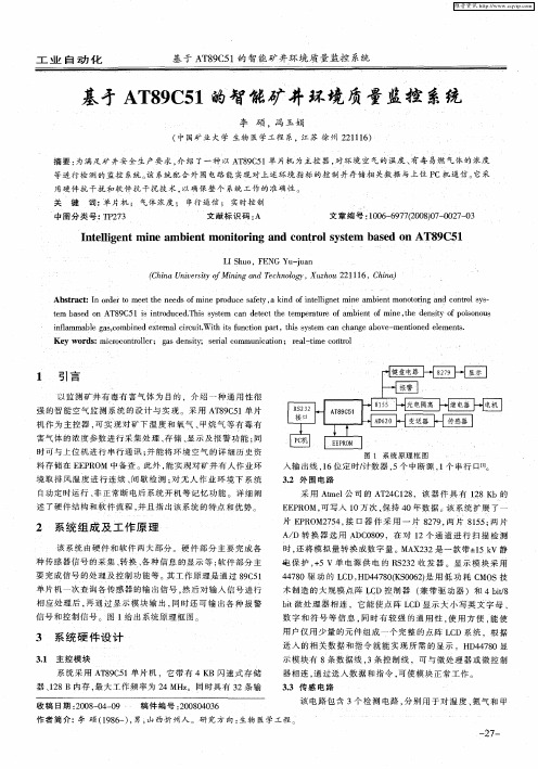
2 系统硬件结构2.1结构框图图1 基于AT89S51单片机的监控与管理系统的结构框图图1所示是基于AT89S51单片机的监控与管理系统的结构框图。
该系统采用了AT89S51单片机系统来控制系统的工作,采用语音专用录音芯片,同时也加上时钟芯片,这样就可以根据自己和场合的需要进行不同的录音,发出适合的报音信号,而且也可以实时显示时钟、日历等,如果选用液晶显示电路,还可以进行文字显示,用于温馨提示,消息或新闻的发布等。
本处只介绍利用语音IC实现报音的提示功能。
该系统由于采用了单片机的软件编程实现控制各模块电路的工作,并且可以通过键盘进行参数的设置,实现了自动控制,使得该系统变得更加完整,功能更多,同时可以进行扩展。
2.2 工作原理1、硬件组成图2 各模块单元电路该系统由AT89S51单片机最小系统电路为主要结构,利用其I/O口进行数据的采集和控制。
图2是各单元电路。
该电路的工作原理是:首先由无线热释电人体红外探头根据人体恒温(37℃)发出特定波长(10uM)的红外线,通过菲泥尔滤光片增强后聚集到红外感应源上,再经热释电元件产生一定的电荷信号并送往单片机,此时单片机马上读取当前时间,并与之前单片机设定的时间段进行比较,如果发现当前时间落在所设时间段围,则向录音电路芯片发出控制信号,把相应时间段的录音容送到报音电路,然后由报音电路通过放大电路放大后驱动扬声器,发出相应的声音;若发现当前时间没有落在所设时间段围,则不响应该次无线热释电人体红外探头送进来的中断信号,即后面的全部工作将不再进行下去,而是等待下一个中断信号的过来。
基于AT89C51的智能矿井环境质量监控系统
关
键
词 : 片机 ; 气 体 浓 度 ; 串行 通 信 ; 实 时控 制 单 文 献标 识码 : A 文 章编 号 :0 6 67 (0 80 — 0 7 0 10 — 9 720 )7 0 2 — 3
中图 分 类 号 : P 7 T23
I e l e i m b e tm o t r n nd c nt o y t m s d o nt li ntm ne a g i n nio i g a o r ls se ba e n AT8 C51 9
2 系统 组 成 及 工 作原 理
该 系 统 由硬 件 和 软 件 两 大 部 分 。 硬 件 部 分 主 要 完 成 各
时 , 将 模 拟 量 转 换 成 数 字 量 。MA 2 2是 一 款 带 - 5k 静 还 X3 + V 1
皂 保 护 , 5 V 单 电源 供 电 的 R 2 2收 发 器 。显 示 模 块 采 用 + S3
32 外 围 电路 .
境 取 排 风 温 度 进 行 连 续 、 歇 检 测 ; 无 人 作 业 环 境 下 系 统 间 对 自动定 时运 行 、 正 常 断 电后 系 统 开 机 等 记 忆 功 能 。详 细 阐 非 述 了硬 件 结 构 和 软件 流程 , 且 指 出该 系 统 的特 点 和 优 势 并
1 引 言
以监 测 矿 井 有 毒 有 害气 体 为 目 的 ,介 绍 一 种 通 用 性很
强 的智 能 空 气 监 测 系 统 的 设 计 与 实 现 。采 用 A 8 C 1 片 T95 单 机 作 为 主 控 器 , 实 现 对 矿 下 温 度 和 氧 气 、 烷 气 等 有 毒 有 可 甲 害 气体 的浓 度参 数进 行 采 集 处 理 、 储 、 示 及 报 警 功 能 : 存 显 同
基于AT89C51CC01单片机的CAN-LIN网关设计
维普资讯
设计天j i 地l 目f 汝 编I 水
基于 A 8 C 1 C 1 T 9 5 0 单片机的 C N L C A — I N网关设计
T e De in o AN— I t wa a e nt e AT 9 C h sg fC LN Ga e y B s d o h 8 C5 COl 1
● 长安大学( 西安) 教育部 “ 道路施工技术与设备”重点实验室 苟伟成
摘 要
本 文 以 AT 9 1 C 3单 片机 为 基础 ,提 出 了一 种 CA ~ 节 省 成 本 。 I 8 C5 C 0 N L N通 讯 是 基 于 S ( CIUAR ) 据 T数
L N 网 关 的 解 决 方 案 ,并 给 出 了其 硬 件 设 计 电路 和 软 件 设 格 式 , 用 单 主 控 制 器 / 从 设 备 的 模 式 , I 采 多 仅
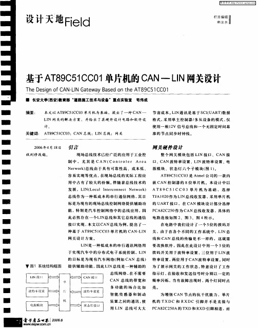
阚关 硬件 设计
整 个 网 关 模 块 包 括 L N 接 口 、 CAN 接 I
收到修改稿 。
制 中 , 尤 其 是 CA N ( COnt ol A r r e 口 、CAN波 特 率 设 置 、L N波 特 率 设 置 、电 r e a I Newok 总 线 由 于 具 有 可 靠 性 高 、 成 本 低 、 源 模 块 、 状 态 灯 六 个 子 模 块 ( 1 。 r r) 图 ) 容 易 实 现 等 优 点 , 现 场 总 线 的 实 际 工 程 应 在
基于AT89S51控制的手机电池质量检测系统

基于AT89S51控制的手机电池质量检测系统
覃毅
【期刊名称】《广西质量监督导报》
【年(卷),期】2008(000)007
【摘要】本文分析了一款基于AT89S51控制的手机电池质量检测系统,提出了系统的软硬件结构设计,阐述了A/D转换器MAX197和显示驱动芯片MAX7219在此系统中的应用方法以及数据处理中使用的数字滤波算法.
【总页数】2页(P94,102)
【作者】覃毅
【作者单位】广西质量技术工程学院,广西,南宁,530022
【正文语种】中文
【中图分类】TM92
【相关文献】
1.基于AT89S51控制的液压避险制动系统的设计 [J], 艾卫东;苗勇
2.基于AT89S51单片机的温湿度监测与控制系统设计 [J], 倪瑞;张万达
3.一种基于AT89S51单片机的可编程作息时间控制器设计 [J], 禹凯歌
4.基于AT89s51控制的指纹密码锁 [J], 姜宁;裴若男;孟萧振;宁秋月;谢印庆
5.基于AT89S51的温湿度控制系统 [J], 裴若男;姜宁;宁秋月;孟萧振;谢印庆
因版权原因,仅展示原文概要,查看原文内容请购买。
基于89C51单片机的太阳能热水器智能控制器的设计

三、软件设计
1、初始化程序
在系统开始运行时,需要先对AT89C51单片机的I/O端口和定时器进行初始化。 I/O端口的初始化需要根据实际连接情况设置输入输出模式;定时器的初始化 则包括设定定时器模式、计数值等。
2、循环控制程序
循环控制程序是LED彩灯控制器的核心部分,主要负责实时监控I/O端口的输 入状态,并根据设定值调节LED彩灯的颜色和亮度。在软件中,可以通过嵌套 循环实现不同LED彩灯之间的切换,利用定时器实现动态效果。
谢谢观看
二、设计思路
LED彩灯控制器的主要设计思路是通过AT89C51单片机控制LED彩灯的颜色和亮 度。AT89C51单片机的I/O端口可以用来连接LED彩灯,通过编程控制I/O端口 的输出电压,可以实现LED彩灯的颜色和亮度的调节。同时,可以利用定时器 实现LED彩灯的动态效果,例如流水灯、跑马灯等。
参考内容
随着科技的进步和人们生活水平的提高,全自动洗衣机已经成为家庭和工业洗 涤的必备设备。全自动洗衣机通过机械和电气的配合,简化了人们的洗衣过程, 提高了洗涤效率。为了进一步优化全自动洗衣机的功能和性能,本次演示将介 绍基于STC89C51单片机全自动洗衣机控制器的设计方法和步骤。
在全自动洗衣机中,单片机担任着重要的控制角色。它负责接收用户的操作指 令,如启动、暂停、模式选择等,并根据这些指令控制洗衣机的各个部件,如 进水管、电机、洗涤程序等,实现全自动洗衣的功能。因此,单片机的设计是 全自动洗衣机控制器的核心。
3、AT89C51单片机的选择
AT89C51单片机是控制器的核心部分,需要根据实际需求选择合适的单片机型 号。在本设计中,可以选择常见的AT89C51单片机,该单片机具有丰富的I/O 端口和定时器资源,能够满足本设计的需求。
基于AT89C51的隧道智能调光系统的设计

DOI:10.16644/33-1094/tp.2019.08.004基于AT89C51的隧道智能调光系统的设计*肖广兵1,陈佳妮1,孙宁1,陈勇2(1.南京林业大学汽车与交通工程学院,江苏南京210037;2.南京林业大学机械电子工程学院)摘要:介绍了以AT89C51单片机为核心控制单元的隧道智能调光系统。
该系统由交直流供电模块、光照强度检测模块、AT89C51控制模块、上位机管理系统、道路监控等组成,利用无线传感网络实现通讯。
通过对隧道内灯光照明的智能调控,使得光线在隧道内呈均匀分布,以保障隧道内车辆驾驶的安全性和舒适性。
文章阐述了隧道智能调光系统的软硬件设计方案。
该系统实现了对隧道内外光线的检测和智能控制,具有结构简单,操作方便等特点,能有效保障隧道路段的交通安全与通行能力。
关键词:隧道照明;智能调光;AT809C51;无线传感网络中图分类号:TP206.3文献标志码:A文章编号:1006-8228(2019)08-10-04Design of tunnel lighting adjust system using AT89C51Xiao Guangbing 1,Chen Jiani 1,Sun Ning 1,Chen Yong 2(1.Nanjing Forestry University College of automotive and transportation engineering ,Nanjing,Jiangsu 210037,China;2.Nanjing Forestry University College of mechanics and electronic engineering )Abstract :The design of a tunnel lighting adjust system with AT89C51is introduced,which includes AC /DC power module,illumination intensity detection module,AT89C51microcontroller unit,PC administration system,real-time monitor,etc.It makes use of wireless sensor network to realize communication.The design of the system ’s software and hardware is introduced,which realizes the detection of the light change inside and outside the tunnel,and the intelligent control.The system has the characteristics of simple structure,convenient operation and so on,and can effectively ensure the traffic safety and traffic capacity in tunnel.Key words :tunnel lighting ;intelligent light-control ;AT89C51;wireless sensor network收稿日期:2019-03-27*基金项目:国家自然科学基金资助项目(61803206);产业前瞻与共性关键技术重点项目(BE2017008-2)作者简介:肖广兵(1984-),男,江苏南京人,博士,讲师,主要研究方向:车载网络通信。
基于AT89C51智能节电器的研究

图 5 智能节电控制器的实验板
参考文献
[ 1] Morad R A , Galasiu A D. Energy performance of daylight - linked automat ic l ighting control syst ems in large atriumspaces: report on two f ield- monitored case st udies. ELSEVIER Energy and Buildings, 2003; ( 35) .
图 1 主回路控制电路图
2. 3 智能节电器硬件系统构成 整个系统硬件结构框图如图 2 所示: 它包括
强电部分、单片机及其外围电路、稳压、滤波、电压 采样电路和显示电路。
图 2 微机控制原理框图
2. 3. 1 系统的电气组成 系统强 电部分 包括一个 三抽头 30KW 变压
器, 两个继电器和一个接触器, 输人为 220V 市电, 输出分别为 200V , 195V, 再 加上 220V, 一 共三 级。根据电网的电压, 系统作出相应的控制策略。 2. 3. 2 单片机与外围电路
输出市电, 并且 AT 89C51 的定时 器开始计 时, 如 果市电平稳, 单片机定时器计时一段时间后, 单片 机通过引脚 p2. 7 输出小继电 器 Apa3319( K2) 控 制 J2 端使其导通, 使继电器 1( RELAY1) 和继电器 2( RELAY2) 线圈得电, 继电器 1 和继电器 2 同时 跳下, 则市 电 经 变压 器 降为 200V 通 过 接触 器 ( KM) 常闭端输出, 进入节电 1 状态。在节电 1 状 态平稳运行一段时间后, 单片机通过引脚 p2. 6 输 出小继电器 Apa3319( K1) 控制 J1 端使其导通, 使 KM 线圈得电, KM 接触器的常开 端闭合, 常闭端 打开输出电压为 195V, 进入节电 2 状态。
基于89C51单片机的多功能智能车设计
基于89C51单片机的多功能智能车设计Abstract: In recent years, intelligent vehicles have received increasing attention due to their potential for improving road safety and reducing congestion. This paper presents the design and implementation of a multi-functional intelligent vehicle based on the 89C51 microcontroller. The vehicle is equipped with various sensors and actuators, including infrared sensors, ultrasonic sensors, line tracking sensors, and DC motors. It also features a wireless communication module that allows it to be controlled remotely. The system is designed to detect obstacles, follow a blackline on the ground, and perform different maneuvers based on varying road conditions. Experimental results show that the intelligent vehicle is capable of performing these tasks effectively and efficiently. The proposed design can serve as a basis for further research in the field of intelligent vehicles.Keywords: Intelligent Vehicle; 89C51 Microcontroller; Sensors; Actuators; Wireless Communication1. IntroductionWith the rapid development of science and technology, intelligent vehicles have become a hot topic in the field of automotive engineering. Intelligent vehicles are designed to improve road safety, reduce congestion, and enhance thedriving experience. They are equipped with sensors and communication devices that allow them to interact with the environment and other vehicles. Moreover, they can perform various tasks autonomously, such as obstacle avoidance, lanedetection, and traffic signal recognition. This paperpresents the design and implementation of a multi-functional intelligent vehicle based on the 89C51 microcontroller.2. System ArchitectureThe intelligent vehicle comprises a 89C51 microcontroller, various sensors, actuators, and a wireless communication module. The microcontroller acts as the brainof the vehicle, controlling the movement of the DC motors and processing the data from the sensors. The sensors used inthis design include infrared sensors, ultrasonic sensors, and line tracking sensors. The infrared sensors are used todetect obstacles in front of the vehicle, while theultrasonic sensors are used to detect obstacles in a wider range. The line tracking sensors are used to follow the black line on the ground. The DC motors are responsible for the movement of the vehicle, and they are controlled by a motor driver circuit based on the 89C51 microcontroller.The wireless communication module is used to control the vehicle remotely. It is based on the ZigBee protocol, whichis a low-power, low-data-rate wireless communication protocol. The system uses two ZigBee modules, one connected to the microcontroller on the vehicle, and the other connected to a remote control device. The remote control device sends commands to the vehicle via the wireless communication module, enabling the vehicle to be controlled remotely.3. System DesignThe main objective of the system design is to enable the vehicle to perform various tasks autonomously. The system is designed to detect obstacles, follow a black line on the ground, and perform different maneuvers based on varying road conditions. The main components of the system are describedbelow.3.1 Obstacle DetectionThe vehicle uses infrared sensors and ultrasonic sensors to detect obstacles in its path. The infrared sensors are mounted on the front of the vehicle and are used to detect obstacles in a narrow range. The ultrasonic sensors are mounted on the sides of the vehicle and are used to detect obstacles in a wider range. The sensor data is processed by the microcontroller, which determines the presence and location of obstacles. The vehicle then takes appropriate action, such as stopping or changing direction, to avoid the obstacle.3.2 Line FollowingThe vehicle uses line tracking sensors to follow a black line on the ground. The sensors are mounted underneath the vehicle and are used to detect the position of the line. The sensor data is processed by the microcontroller, which determines the direction and speed of the vehicle. Thevehicle then adjusts its movement to follow the line.3.3 ManeuversThe vehicle is capable of performing different maneuvers based on varying road conditions. For example, it can perform a U-turn if it encounters an obstacle in its path or if it loses track of the line. It can also adjust its speed based on the distance to an obstacle or the curvature of the line.4. Experimental ResultsThe proposed design was implemented and tested in a laboratory setting. The vehicle was able to detect obstacles in its path, follow a black line on the ground, and perform different maneuvers based on varying road conditions. The wireless communication module allowed the vehicle to becontrolled remotely, enabling it to perform different tasks from a distance. The results demonstrate that the proposed design is effective and efficient in performing various tasks autonomously.5. ConclusionIn this paper, the design and implementation of a multi-functional intelligent vehicle based on the 89C51 microcontroller was presented. The vehicle was equipped with various sensors and actuators, including infrared sensors, ultrasonic sensors, line tracking sensors, and DC motors. It also featured a wireless communication module that allowed it to be controlled remotely. The system was designed to detect obstacles, follow a black line on the ground, and perform different maneuvers based on varying road conditions. The experimental results showed that the vehicle was capable of performing these tasks effectively and efficiently. The proposed design can serve as a basis for further research in the field of intelligent vehicles.。
- 1、下载文档前请自行甄别文档内容的完整性,平台不提供额外的编辑、内容补充、找答案等附加服务。
- 2、"仅部分预览"的文档,不可在线预览部分如存在完整性等问题,可反馈申请退款(可完整预览的文档不适用该条件!)。
- 3、如文档侵犯您的权益,请联系客服反馈,我们会尽快为您处理(人工客服工作时间:9:00-18:30)。
2 电池 组 智 能 管 理 系统 硬 件 设 计
监控 系统 的硬件 结构 主要 包括 0 8 0锂 电池智 能 管 Z9 理模 块 、监控模 块 、显示模 块和声 光 报警模 块 。 ( )主控 MC 电路 。主控 MC 1 U U采 用 A 8 C 1 C 1 T 9 5C 0 单 片机 ,它是 一种 功能 强大 的 8位微 控制 器 。自带 C AN 控 制 器 和 内 置 3 B F AS RO 2 K L H M。2 E R M 和 KB E P O 1 K A . B R M。可 控制 1 2 5个 C AN通 道 ,这些 通 道 可 编程
的功 能更 完善 。
管理 ,将会 使 蓄 电池 组 内单 体 之 间的差 异在 使 用过 程 中 逐 渐 增 大 ,导 致 电池 组 在 运 行 一 段 时 间后 出现 单 体 过 充 、过 放 、过 流及 电池组 环 境 温 度过 高 等一 系 列 故 障 , 造 成整个 电池 组 的使 用 寿命 缩减 .性 能下 降 .严 重 时甚
时 显 示 电 池 组 的 各 种 状 态 ,发 挥 了 电 池 组 整 体 的 最 大 性 能 . .
关 键 词 : 智 能 管 理 模 块 :S OC; 能 量 均 衡 :A 9 5 C 1 T8 C 1 C0
中图分类 号 :T 4 B7
文献 标识 码 :A d i 03 6 /.s . 0 — 6 32 1 . .5 o: .9 9j sn1 2 6 7 .0 1 60 8 1 i 0 0
电流 、剩 余 电量
等 。 I 电路 如 2 C
图 2所 示 .XS 2
根 据 电量估 测算法 ,对 电池 的 当前 电量进 行估 算 ;数 据 采 集模块 负责采集 电池 的各 种状 态参数 ,如 电流 、电压 、
温 度 ;数据 显示模 块采 用 图文 液 晶显示 屏 .显 示 各节 电
用 于接 收 、发送 或接 收缓 冲器 。可 为 网络节 点 提供 硬 件
支 持 .并且 内部 还有 D转换 和 P WM 发 生 器等 其 他 功 能 ,在设 计 中可直接 用 于电池 电压 的测量 。
( )通讯 电路 。 系统使 用 串行 接 口 ,通 过 液 晶模 块 2
显 示 电 池 组 总 电 压 、各 单 节 电 池 电 压 、充 放 电
数 据 监控 、报 警 。选用 锂 电池 专 用管 理 芯片 O 8 0。实 Z9
收 稿 日期 :2 1 —1 — 3 0 1 0 0
作 者 简 介 : 吴 昌 江 ( 9 1 ,大 学 专 科 ,维 修 电 工 高级 工 。 1 9 一)
现过 压 、欠压 、过 流 、短路 、过 高 温及 过低 温保 护 、电
池 能量均 衡 和数 据采 集等 功能 ,在此 基 础上 选用 单 片机 A 8 C 1 C 1 控制器 。设 计 了声光 报警 系统 。同时通 T9 5C O 为
过 L D点 阵液 晶显示屏 进行 动态全 面 显示 ,使 锂 电池组 C
是 信 号 输 入 端
和电源端插 座 .
池 电压 ,充 放 电电流 ,剩余 电量 ,电池温度 和充 电时间。
本 文设 计 的动力锂 电池 组 管理 系统 能对 电池 组进 行
输 入 的 信 号 经
过 MC 处 理 . U 发 送 到 L D 进 C 行 显 示 :R 2 2 S3
的 过 充 、 过 放 、 过 流 、 过 热 等 保 护 功 能 。 在 此 基 础 上 ,为 使 系 统 更 加 完 善 。 选 用 单 片 机 A 9 5 ccO T8 c 1 1为 主控 制 器进 行设 计 ,使 系统 具 有 声光报 警 等功 能 .且 能通 过 L D 液 晶显 示屏 实 C
第2 4卷 第 6期 2 1 0 1年 1 1月 文章 编 号 : 10 — 6 3 (0 1 6 4 — 2 0 2 6 7 2 1 )0 —14 0
D v lp n e eo me t& I n v t n o a hn r & E e t c lP o u t n o ai f c iey o M lcr a r d cs i
系 统 ,以有效 解决 电池 组 的安全 问题 ,确保 锂 电池 组可 靠 运行 ,同 时延 长 电池组 使用 寿命 ,降低使 用成 本 。
1 电池 智 能 管 理 系统 的 结构
基 于 0 8 0的锂 电池组 智能 管理模 块 ,主要 由充 电 Z9 模 块 、数据 采集模 块 、均衡 模块 、电量计 算模 块 、数据 显示模 块等 组成 。充 电模块 按预 充 、恒流 充 电和恒 压充 电i个 阶段 进行 自动充 电 ,并根 据采 集 的数据 对充 放 电 过 程进 行控 制 ;均 衡模 块在 适 当的 时候通 过开 关 电源 对 单 个 电池进 行 均衡 充 电 ,使 电池 组 中 的能 量 均衡 一 致 ; 电量计 算模 块是通 过对 采集 到 的状 态参 数进行 分 析 ,并
0 引 言
锂 电池 以卓 越 的性 能 、体 积小 、重 量轻 及环 境 污染 小等 独特 的优 势 ,成 为 电动 汽车蓄 电池 的理想 选择 。电 动 汽车 的锂 电池组 由多节 单 体 电池 串联 组 成 ,总 电压一 般 在 1 ~ 0 V。如 果不 对 蓄 电池 组进 行 安全 监控 和有 效 24 0
机 电产 品开 崖 与 ቤተ መጻሕፍቲ ባይዱ
Vo.4, 6 1 2 No. No . 11 v, 20
基 于 A 8 C 1 C 1的锂 电池组智能管理监控 系统设计 T 9 5 0 C
吴 昌 江
( 州 职 业技 术 学 院 ,浙 江 杭 州 30 1 ) 杭 10 8
摘
要 :给 出了一种 锂 电池 组管 理 系统 的设计 方 法 。系统选 用 OZ 9 8 0锂 电池 专 用管理 芯 片 , 实现 了蓄 电池