火车原油储罐清洗
原油储罐机械清洗与人工清洗详细对比精选全文完整版
污水需进入沉降罐待处理
原油回收率大于98%
原油回收率低
用途
除用于罐底油泥及老化油的处理,还可用于集油坑、污油池的处理
仅用于储罐清洗后期的油水粗分离。
罐内推泥车作业与人工推铲对比
项目
液压推泥车
人工推铲
安全性
人员可在罐外遥控作业,无安全风险。
人员需进罐进行推铲、装袋作业,易造成人员中毒。
2、易产生静电,易发生爆炸事件。
保护环境
1、清洗、回收是封闭式,并可进行油水、油泥分离。
1、清洗后不可利用的沉积物多且不易处理,造成环境污染。
2、不需要额外的废物处理设施。
2、没有废物处理装置,使废物污染环境。
资源再利用
1、油回收率达90%以上
1、油回收率低。
2、回收油品质好,回收原油中几乎不含水分及固体杂质。
效率
2-3人配合作业。
工作量大,需投入20人
液压吸泥机直接将油泥送入三相离心机。
罐内油泥装入编织袋后靠人力外运。
保护环境
油泥通过管道外输,直接进行处理。
油泥在罐外堆放,靠车辆外运。
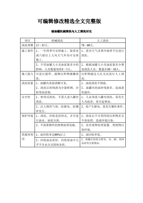
可编辑修改精选全文完整版
储油罐机械清洗与人工清洗对比
项目
机械清洗
人工清洗
清洗周期
15~35天。
70~90天。
施工条件
1、一年四季可安排施工,除雷电或六级以上大风天气外均可安排施工。
1、恶劣天气及寒冷地带不宜进行清洗。
2、不受油罐大小及油泥量多少的影响,人员数量每班3~5人。
2、根据油罐大小及油泥量多少增加清洗人员,数量在30~50人。
2、蒸罐后轻组分挥发,水、蜡、固体杂质等含量增高。
声纳淤积探测与人工检尺对比
油罐清理方案

油罐清理方案1. 引言油罐清理是指对存储油品的罐体进行清洗、排污、除垢和除油腻等处理的过程。
它是保证油罐安全、维持油品质量以及延长使用寿命的重要环节。
本文将介绍一种高效、安全、环保的油罐清理方案,旨在为油罐清理工作提供参考和指导。
2. 前期准备工作在进行油罐清理之前,需要做一些前期准备工作。
包括以下几个方面:2.1 罐内油品处理首先,需要将油罐内的油品进行排空处理。
这可以通过连接抽油管道,并利用抽油泵将油品抽出罐体。
2.2 罐外油品处理在油罐清理过程中,不可避免地会有一些油品溢出或流出罐体。
为避免对环境造成污染,需要在油罐周围铺设防油布,以便收集和处理溢出油品。
2.3 工作区域准备在清理油罐之前,需要将工作区域进行划分,并进行清理和整理。
确保工作区域的通风良好,并设置好安全警示标志。
3. 清理工具与设备油罐清理需要用到一些特定的工具和设备,包括以下几项:3.1 清洗设备清洗设备主要包括高压水枪、清洗液泵和清洗管道等。
高压水枪用于喷射高压水流进行罐内壁面清洗;清洗液泵用于将清洗液送入罐内;清洗管道用于将清洗液和污物排出罐体。
3.2 安全防护装备在进行油罐清理时,需要佩戴防护眼镜、防护手套、呼吸器等安全防护装备,确保人员安全。
3.3 其他工具还需要准备一些常见的工具,如扳手、铁锤、刷子等,以应对不同情况下的操作需求。
4. 清洗步骤下面是油罐清理的一般步骤:4.1 罐内油渣清理首先,使用清洗设备中的高压水枪,对罐内壁面进行清洗。
将高压水枪喷射到罐内的油渣上,使其软化,并通过清洗管道将油渣排出罐体。
反复清洗,直到罐内壁面干净为止。
4.2 污物除去在清洗完罐内壁面后,使用刷子等工具将污物彻底清除。
注意不要将污物沾染到外部环境,需及时收集和处理。
4.3 清洗液处理将清洗液排出罐体后,需进行处理,以防止对环境造成污染。
将清洗液收集到专门的容器中,然后送至处理站点进行处理。
4.4 罐内干燥在清洗完罐体后,需要将其内部充分干燥。
石化行业铁路罐车清洗方法综述
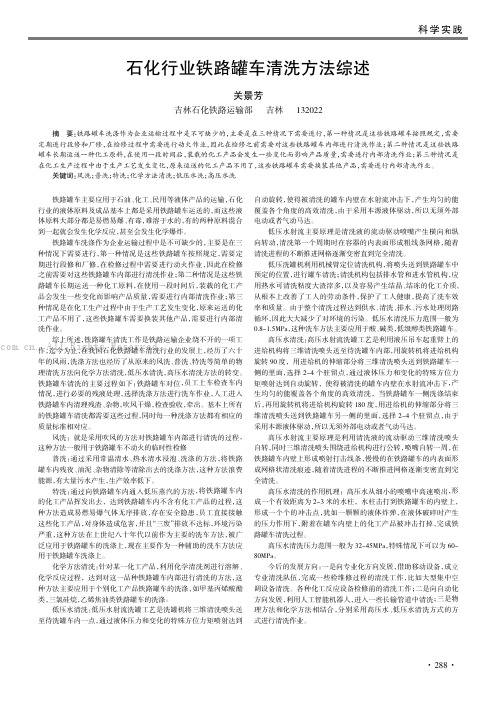
铁路罐车主要应用于石油、化工、民用等液体产品的运输,石化行业的液体原料及成品基本上都是采用铁路罐车运送的,而这些液体原料大部分都是易燃易爆、有毒,难溶于水的,有的两种原料混合到一起就会发生化学反应,甚至会发生化学爆炸。
铁路罐车洗涤作为企业运输过程中是不可缺少的,主要是在三种情况下需要进行,第一种情况是这些铁路罐车按照规定,需要定期进行段修和厂修,在检修过程中需要进行动火作业,因此在检修之前需要对这些铁路罐车内部进行清洗作业;第二种情况是这些铁路罐车长期运送一种化工原料,在使用一段时间后,装载的化工产品会发生一些变化而影响产品质量,需要进行内部清洗作业;第三种情况是在化工生产过程中由于生产工艺发生变化,原来运送的化工产品不用了,这些铁路罐车需要换装其他产品,需要进行内部清洗作业。
综上所述,铁路罐车清洗工作是铁路运输企业绕不开的一项工作,迄今为止,在我国石化铁路罐车清洗行业的发展上,经历了六十年的风雨,洗涤方法也经历了从原来的风洗、普洗、特洗等简单的物理清洗方法向化学方法清洗,低压水清洗,高压水清洗方法的转变。
铁路罐车清洗的主要过程如下:铁路罐车对位,员工上车检查车内情况,进行必要的残液处理,选择洗涤方法进行洗车作业,人工进入铁路罐车内清理残渣、杂物,吹风干燥,检查验收,牵出。
基本上所有的铁路罐车清洗都需要这些过程,同时每一种洗涤方法都有相应的质量标准相对应。
风洗:就是采用吹风的方法对铁路罐车内部进行清洗的过程,这种方法一般用于铁路罐车不动火的临时性检修普洗:通过采用常温清水、热水清水浸泡、洗涤的方法,将铁路罐车内残夜、油泥、杂物清除等清除出去的洗涤方法,这种方法浪费能源,有大量污水产生,生产效率低下。
特洗:通过向铁路罐车内通入低压蒸汽的方法,将铁路罐车内的化工产品挥发出去,达到铁路罐车内不含有化工产品的过程,这种方法造成易燃易爆气体无序排放,存在安全隐患,员工直接接触这些化工产品,对身体造成危害,并且“三废”排放不达标,环境污染严重,这种方法在上世纪八十年代以前作为主要的洗车方法,被广泛应用于铁路罐车的洗涤上,现在主要作为一种辅助的洗车方法应用于铁路罐车洗涤上。
石油储运中的油罐清洗与养护
石油储运中的油罐清洗与养护油罐作为石油储运系统中的重要组成部分,在保证石油贮存安全与质量的同时,需要进行定期的清洗与养护。
本文将介绍石油储运中油罐清洗与养护的重要性、清洗方法以及养护措施。
一、清洗与养护的重要性油罐清洗与养护的重要性不容忽视。
首先,清洗可以有效去除油罐内残留的油污、沉积物和杂质,避免其对石油贮存质量的影响。
同时,清洗还能清除因沉积物引发的火灾和爆炸风险,确保油罐运行的安全性。
其次,养护措施如防腐蚀涂层的维修和更新,能够延长油罐的使用寿命,降低维护成本,并减少环境污染风险。
二、清洗方法1. 油罐内部清洗油罐内部清洗通常包括机械清洗和化学清洗两种方法。
机械清洗采用高压水枪或刷子,通过冲刷和擦拭的方式,清除油污和沉积物。
化学清洗则是使用特定的溶剂或清洗剂,可以有效分解和溶解油污,并彻底清洁油罐内部。
2. 油罐外部清洗油罐外部清洗主要目的是去除油污和杂质,以维持罐体表面的清洁。
常见的清洗方法包括高压水洗、蒸汽清洗和化学清洗。
高压水洗适用于一般污染程度的油罐表面清洗,蒸汽清洗则适用于较为严重的污染情况。
化学清洗常用于处理特殊情况下的污染,如油脂结垢或腐蚀物。
三、养护措施1. 防腐蚀措施油罐内外表面的防腐蚀涂层是维护油罐的重要手段。
定期检查罐体表面涂层是否受损,如有受损应及时修补,以提高涂层的使用寿命。
此外,还可以进行防腐蚀涂层的更新,从而保障油罐的长期使用。
2. 管道清理除了油罐本身,管道系统的清洗也是油罐清洗与养护的一部分。
管道清理主要是为了避免管道内部的积垢和油污对油品贮存的影响。
常见的管道清洗方法包括管道吹扫、高压水冲洗和化学清洗等。
3. 定期检测与维护定期检查油罐的运行状态和安全设备是否正常工作,并进行必要的维护和更换。
同时,还要定期进行罐底、罐壁和罐顶的检查和测试,确保油罐在使用过程中没有安全隐患。
总结起来,石油储运中油罐清洗与养护是确保石油贮存安全与质量的重要环节。
通过油罐的定期清洗、养护措施和管道的清理,可以确保油罐内外表面的清洁,延长油罐的使用寿命,减少安全风险,并最大限度地保护环境。
原油储罐清洗过程!

储罐清理施工方案原油储罐在使用过程中,由于生产经营需要,更换储存其他油品,需对原油储罐进行清洗。
由于原油闪点低于28度,属于一级危险品,油蒸气不仅易燃、易爆而且有毒,因此,清洗油罐是一项比较危险的作业。
储罐清洗方法有4种,即干洗法、湿洗法、蒸汽洗法和化学洗法。
而将蒸汽法与干洗法结合使用,则可达到高效、经济的目的。
一、油罐清洗作业步骤清洗作业既要保证罐内原油全部倒净,最大限度地降低在倒罐过程中原油的损耗,又要保证油罐的清洗质量,同时在倒罐与洗罐过程中要特别注意安全。
1、倒罐:就是把要清理的罐内的原油倒到另一储罐中。
2、注水加温3、打开人孔通风:停止蒸汽加温,打开油罐的人孔,采用隔爆型轴流式换气扇向油罐内通风。
4、进罐清油:①操作人员进罐前,先用隔爆型轴流换气扇在储罐人孔处通风24小时,再用测爆仪及测氧仪进行测试,确认合格后,才能进罐作业。
②进罐作业人员必须穿防静电工作服及防滑静电鞋,清油工具要选用木锹或铜制工具。
清罐过程中,现场安排专人监护,必要时进罐人员需戴防毒面具和信号绳。
进罐时间不宜过长,一般在15-20分钟,轮班作业。
同时,储罐的人孔处要用换气扇鼓风,现场应有医护人员值班。
二、洗罐操作要点1、人工清罐结束后,储罐内已基本无明显油块,此时先用锯末屑对罐壁、罐底板、加温盘及支架等彻底擦洗一遍,清出木屑后,再用棉纱蘸柴油,对以上部位再擦洗一遍。
擦洗干净后,用干净棉纱或拖把再彻底擦抹一遍,最后将罐内杂物清理干净。
2、如果有特殊要求,可用铜制工具去除局部锈蚀。
在油罐洗罐过程中,现场需配备一些消防器材,同时消防泵房要安排专人值班。
安全操作方案第一章总则为了做好油罐清洗工作保障油罐清洗人员的作业安全和身体健康,防止发生各类事故,根据“预防为主”的方针,特制定本方案。
一、操作人员作业之前,应根据分工情况对有关人员进行安全和相关操作进行岗前教育;二、作业人员进罐检查或作业时,油罐人孔外均须设专职监护人员,且一名监护人员不得同时监护两个作业点;三、安全员应加强现场的安全监查,并有权制止违章指挥和违章作业并及时报告有关领导;四、班组负责人和安全监护员应做好交接班的现场安全检查、清点人员及其工具器材等工作;第二章一般安全规定五、作业场所应确定安全距离,设置安全界标或栅栏,并应有专人负责对所设置的安全界标或栅栏进行监护;六、为了防止清罐作业人员中毒,必须做到:1.当油气浓度为该油品爆炸下限的4-40%时,进入油罐的作业人员必须佩戴隔离式防毒面具;2.当油气浓度超过该油品爆炸下限的1%并低于4%时,允许作业人员在不佩戴呼吸器具的情况下短时间进罐作业,但应佩戴防毒口罩且每次作业不应超过15分钟;同时,每工作日最多重复工作四次,时间间隔不少于1小时。
原油储罐机械清洗技术及应用

原油储罐机械清洗技术及应用摘要在石油工业中,储罐是必不可少的设备,但长期运行后会积累很多污垢和沉淀物,这些物质会导致储罐内部腐蚀和安全隐患。
因此,及时清洗储罐变得非常必要。
本文提出了一种机械清洗技术,可以高效、安全、节约成本地清洗原油储罐。
1. 原油储罐清洗的必要性原油储罐通常由一种或多种类型的原油混合物构成,这些原油混合物在储罐内长时间存放时容易形成沉积物和腐蚀。
这些积累物不仅会影响原油的品质,还会导致储罐本身的腐蚀和安全隐患。
因此,定期的储罐清洗是必不可少的。
传统的储罐清洗方法包括水冲洗、化学清洗以及手工清理等,这些方式都存在一些缺点。
水冲洗过程中,水很难进入难以清洗的角落和缝隙,可能导致残留物仍然存留在储罐中。
化学清洗的过程中,使用的化学物质会对环境造成污染,而手工清理的方式则需要消耗大量的人力,效率低下。
机械清洗技术则解决了上述问题,本文将介绍其具体过程及优势。
2. 原油储罐机械清洗技术机械清洗技术是一种高效的清洗方式,主要是通过机械设备对储罐内壁进行清洗,从而去除污垢和沉积物。
通常的机械清洗设备包括水平刮板机、旋转刮板机和高压清洗机等。
这些机械装置能够有效地清除铁锈、积垢以及其他罐内残留物。
具体来讲,机械清洗过程包括以下几个步骤:1.简单检查储罐外观和内部空气质量等情况,确保安全。
2.焊接机械臂和平台以便自上而下地对储罐进行清洗,清洗过程中,机械臂和平台将钢刷放入储罐内,通过转动钢刷完成清洗过程。
3.使用高压水枪清洗剩余杂质和残留物,确保储罐内部干净。
4.通过唧筒泵将污垢送到处理厂进行处理,以达到环保清洗的要求。
需要注意的是,机械清洗过程中需要严格把关火源,以免引发安全事故。
同时,清洗过程中如果储罐内氧气浓度过高,也会对人员造成危险。
3. 原油储罐机械清洗技术的优势相比于传统的清洗方式,机械清洗技术具有以下优势:1.高效:机械清洗技术的清洗速度非常快,通常只需要几个小时即可完成储罐的清洗任务。
清洗原油罐应急方案
清洗原油罐应急方案1. 前言原油罐清洗是一个不可避免的过程。
清洗过程中,需要严格遵守标准操作程序,加强安全防护,防止事故的发生。
本文将从原油罐清洗前准备、清洗过程以及清洗后的处理等方面进行详细说明。
2. 准备工作进行原油罐清洗前,需要做好以下准备工作:2.1. 检查设备检查清洗设备的运转状态,确保设备正常工作。
2.2. 确认清洗介质确认清洗介质的种类和数量,并进行充分的准备。
2.3. 排水准备准备好排水管道和测量工具,确保出水达标。
2.4. 清洗策略根据不同的原油罐,制定相应的清洗策略。
2.5. 应急预案制定清洗中可能出现的问题和应急处理预案,做好事故预防工作。
3. 清洗过程3.1. 罐内净化打开罐罩,排除罐内沉淀物和杂质,净化罐内环境。
3.2. 清洗介质进罐将清洗介质泵入罐内,使清洗介质充分润湿内壁,同时卷起杂质。
3.3. 油水分离将罐内介质倒出并过滤,分离油水,保留清洁介质,处理废油。
3.4. 洗涤反复进行清洗介质泵入和排出,直至罐内干净无异味。
3.5. 除残留介质使用化学试剂除去残余清洗介质,彻底清洗内壁。
3.6. 检查罐壁检查罐内壁是否干净,如有残余沉淀物需重新清洗。
4. 清洗后处理4.1. 排放清洗液按标准排放清洗排放的废液,做好环保工作。
4.2. 处理废油对废油进行专业处理,做好环保工作。
4.3. 消毒对罐内进行消毒处理,确保罐内无菌。
4.4. 封闭罐体关闭罐口,对罐内进行封闭处理。
5. 结束语清洗原油罐是一项非常重要的工作,必须严格遵守标准操作程序,细致入微地做好安全防护工作,确保清洗过程顺利进行。
同时,做好清洗后的处理工作,保证环境保护工作得到落实。
储油罐清洗安全操作规程
储油罐清洗安全操作规程储油罐是储存液体石油产品的重要设施,其正常运行对于保障石油市场供应和保护环境安全至关重要。
储油罐的清洗操作是其日常维护工作中的重要环节,正确的清洗操作能够有效保证储油罐的安全和长期使用。
本文将介绍储油罐清洗的安全操作规程,以帮助保证储油罐清洗工作的安全性和高效性。
首先,在进行储油罐清洗前,必须做好仔细的准备工作。
首先,清洗人员必须穿着符合安全要求的防护服,并检查其是否完好。
同时,需要检查清洗工具是否齐全,并确保清洗设备处于正常工作状态。
其次,清洗人员需要检查储油罐内的残留物情况以及可能存在的危险因素,例如可燃气体的存在。
如果有必要,可以在清洗前对储油罐进行适当的通风或气检操作,以确保清洗过程的安全性。
最后,清洗人员应当详细了解储油罐的结构和特点,掌握相关情况,并与其他工作人员进行沟通和协调。
其次,进行储油罐清洗时,应当注意使用合适的清洗方法。
清洗方法可以根据不同的储油罐情况选择,例如物理清洗、化学清洗或高压水清洗等。
物理清洗通常包括刮槽、刷洗和砂磨等方法,适用于一些轻度沉积物的清除。
化学清洗则使用特定的清洗剂来溶解、分解或去除罐内的污垢,适用于较为顽固的污垢。
高压水清洗则通过高压水射流来冲刷罐内的污垢,适用于一些较大面积的污垢清除。
不同的清洗方法需要根据具体情况进行选择,尽量避免对储油罐内壁造成损害。
再次,储油罐清洗过程中应当注意安全措施。
首先,在清洗过程中,清洗人员需要佩戴符合要求的个人防护装备,如安全帽、口罩、手套等。
特别是在进行化学清洗操作时,应当戴上专门的化学防护眼镜和防护服,以避免化学物质对面部和皮肤的损伤。
其次,清洗现场需要设置明显的警示标志,警示其他人员禁止靠近并采取必要的安全防护措施。
再次,储油罐的清洗应当由经过专业培训并持有相应证书的人员进行,以确保其具备相应的操作技能和安全知识。
储油罐内部的清洗作业应有两名以上工作人员同时进行,以确保工作的安全性和高效性。
- 1、下载文档前请自行甄别文档内容的完整性,平台不提供额外的编辑、内容补充、找答案等附加服务。
- 2、"仅部分预览"的文档,不可在线预览部分如存在完整性等问题,可反馈申请退款(可完整预览的文档不适用该条件!)。
- 3、如文档侵犯您的权益,请联系客服反馈,我们会尽快为您处理(人工客服工作时间:9:00-18:30)。
INTERNAL AUTOMATED MODULAR WASHING SYSTEM FOR TANKERS AND RAILCARSKMT INTERNATIONAL INC.presents complete stationary modular internal washing systems for tankers and railroad cars after caring petroleum products.System performs high quality clean up of trucks and rail tanks. Washing solution is recycled for multiple usages.System versatility is secured by its ability to clean tanks used for transportation of different oil products with any residual product quantities.Compliance with safety requirements is achieved by using mostly hydraulic system, instead of electric motors, as well as excluding personnel presence during washing cycle inside the tank.Washing solution recycling dramatically reduces waste water discharge.The process was designed after many years of research and development. System utilizes closed washing cycle, which excludes personnel contact with tanks internals, increasing safety and efficiency of system operation.1. System performanceOur washing system is able to wash 30-40 single railroad cars (60 metric tons capacity) per day used for heating oil (heavy oil) transportation and corresponding quantity of tanker cars depending on their size.System can also be used to wash railroad car tanks and tanker cars used for diesel or gasoline transportation. In this case throughput will be doubled.System operator selects pre-programmed washing program determined by transported product.Tanks used for heating oil (heavy oil) transportation are washed in three cycles; using cutter stock then following washing with caustic solution and finally rinsing with hot water.Tanks used for gasoline or diesel fuel transportation are washed in two cycles using caustic solution and rinsed with hot water.2. Tankers and railcars washing process descriptionSingle unit is capable to wash two tanks placed on adjacent parallel tracks at a time: (while two tanks placed along each side of washing station on rail tracks are washed, the other two tanks are prepared). Length of washing cycle is selected by operator.Washing cycle gasoline and diesel cars:-Wash for 15-20 minutes using water and caustic (pH 12-14) at 65°C.-Rinse for 15-20 minutes using water at 65°C.-Allow car to air-dry and cool before closing and sealing manway.Washing cycle heating oil (heavy oil) cars:-Tank pre heating (if required) by steam before washing.-Wash for 45-60 minutes using cutter stock) at 65°C.-Wash for 15-20 minutes using water and caustic (pH 12-14) at 65°C.-Rinse for 15-20 min utes using water at 65°C.-Allow car to air-dry and cool before closing and sealing manway.During washing cycle residual oil product is recovered and rail car is prepared for product change or repair. Our equipment excludes personnel presence inside car during washing cycle. Car conditions and amount of residual products is inspected by operator before choosing washing cycle.Any significant amount of residual product is pumped to special storage tank provided by Customer. Product recovered and regenerated during washing cycle also stored in a special storage tank. Car inspection allows operator determine required washing time as well as washing cycle settings.After car is set for washing, top manway is opened and special manway adapter with telescopic washing apparatus is installed (See Photo #1-4, Photo #6 and Pic. 1), hoses are connected and the washing cycle started. Telescopic washing apparatus is equipped with orbital washing heads (See Photo #5 and Pic. 2). During prewashing inspection, operator selects washing and rinsing solutions type and then solutions are pumped to appropriate tanks. In case car was used for heating oil transportation and is being prepared for product change, cutter stock will be used as washing solution. Caustic solution will be used for rinsing and hot water for final stage.3. Washing process with telescopic apparatusPhoto #1-2. Extending telescopic apparatus.Photo #3-4. Extending telescopic apparatus (continued).Telescopic apparatus with washing heads specially designed to safely and effectively wash tank internals, especially unreachable parts in the car ends. Before such apparatus was designed regular manway adaptor with a single washing head was used. This approach was not very effective in such places.Photo #5. General view if two and three nozzle orbitalwashing heads (stainless steel or bronze).Orbital washing head is rotating in horizontal and vertical axes and driven by washing liquid pressure only (See Pic. 1).Pic. 1. Principle of washing head operation.Pattern formed by water jets covers all internal surfaces of the tank.Strong jets heat and dilute bottom sludge by heated washing solution and strong impact. Such jets impact has greater effect on sludge dilution that simple sludge heating. However kinetic energy of water jets lessens with distance increase from the orbital washing head nozzle. Thus system with one central washing head usual has greater efficiency in central part of the tank (near manway) and is declining toward tank ’ ends. To speed up cleaning, operator should enter inside the tank and complete work manually by scrapping it and using hand water gun. This method is not safe and requires long hours of manual labour.Rotation is drived by liquidflowNozzle rotation in vertical axisHead rotation on horizontal axisWashing liquidProposed hydraulically actuated telescopic apparatus with washing heads simplifies and speeds up cleaning process while provides high efficiency and cleaning quality at the car ends by delivering washing heads much closer to the cars ends.Pic. 2. Extended and unfolded telescopic apparatus inside car.3.1. Telescopic apparatus installation.Photo #6. Telescopic apparatus installation on the car manway.Folded telescopic apparatus is lowered to the cars manway by on-board equipment or other lifting device. Later on, telescopic apparatus will be unfolded to the working position with hydraulic actuators. Apparatus equipped with two orbital washing heads which allow washing both car sides at same time. Washing cycle of car internals can be started as soon as a telescopic apparatus is unfolded, while it will slowly extends to a maximal length, which also reduces required washing time. After washing cycle ends telescopic apparatus retracts and folds in reverse order and then lifted from the car.Washing solution heated to 80Сwill be used in washing cycle. High pressure liquid jets provide maximum impact and cleaning effect to remove sedimentation and residual product from tank walls.Pic. 3. Three positions of washing telescopic apparatus.4. Washing process descriptionWashing agent is preheated in recirculation cycle where it flows from storage tank through strainer, main washing pump, heat exchanger and then back to storage tank. After washing agent reach required temperature washing cycle will be started.Following is the cleaning sequence for tanks carried heating oil (See Pic. 4). Washing pump delivers washing agent (cutter stock) from tank #1 through strainer and heat exchanger to the washing heads on the telescopic apparatus previously installed with crane on the car manway. The effect of high temperature and high pressure washing agent, flowing through orbital washing heads, softens and washes away sedimentation and sludge from internal surfaces of the tank.Washing agent with suspended residual product and sediments is returned to the tank #1 from the washed car by vacuum.Vacuum is created by vacuum pump in the tank #1. Exhaust from vacuum pump is cleaned in one of the scrubbers (depending on the car tank product). Vapours at the scrubber are cleansed by continuous flow of water and active agent. Gases can be additionally cleaned after scrubber at the active carbon filter. Loss of product will be reduced by recovering it from the vapours in scrubber. Liquid sprayed in the scrubber condenses some vapours which then can be added to process tank.Washing agent separates by gravity in the tank #1. Heavy phase collected in conical bottom part and periodically pumped (as soon as sufficient level is reached) by diaphragm pump to the Customers sludge collection tank.During washing cycle washing agent is slowly saturated with heating oil that reduces its washing properties. To avoid this, part of washing agent will be removed as a sellable product (high quality heating oil) and additional fresh washing agent (cutter stock) will be added. Two cars can be washed simultaneously. Washing process for both cars is identical. After first washing cycle is completed, second cycle, by heated caustic solution from tank #2 is started which then is followed by rinsing with hot water from tank #3.Washing process with caustic solution or following hot water rinsing is similar to described previously. Sludge and solids collected in conical tank bottoms are periodically pumped to storage tank supplied by customers.Floating oil and foam rising to the surface are collected on weir plates installed inside tank. Part of the removed washing solution, has to be replaced by fresh agent. Washing agent can be reused many times. Washing solutions can be stored for farther usage to wash car tanks used for same or similar petroleum products.Similar to washing with cutter stock, caustic solution and rinsing solutions are returned to process tank by vacuum created by vacuum pump in the process tank. Vapors and gases from stainless steel vacuum pump are cleaned in scrubbers by continues flow of liquid. Cleaned gases after scrubber can be additionally filtered on carbon filters before they are discharged to atmosphere.When tank with high residual petroleum product and high sediments amount are cleaned, washing agent and solutions become highly contaminated. To check their quality, samples should be taken and analyzed periodically. If required washing agent and solutions should be replaced or diluted with fresh solutions from storage tanks.5. Factory ready module unitsHighest quality parts are used during equipment production. All equipment is grouped to several modules mounted on frames. Module size allows easy transportation without damaging equipment (See Photo #7). When modules are delivered to the site they can be easily assembled according to assembly plan, utilizing easy access to piping and cable connections. Minimal time required for the complete assembly.Factory module preassembly and vigorous testing guaranties high quality and reliability as well as final assembly and startup time reduction.Hydraulic drives and actuators widely use through the system. Only time tested and approved hydraulic equipment (hydraulic motors and control devices) used in system production.KMT International Inc Environmental Engineering CompanyPhoto #7. Factory tested module unit ready for shipment.Photo #8. One of modules installed it the railroad car tanks washing shop.6. Operation safetyProposed washing system practically excludes personal exposure to petroleum products. Telescopic apparatus use of heated solutions under high pressure effectively replaces manual labor.Only explosion proof or intrinsically safe equipment is used in order to guarantee safety of working personnel. Wide usage of hydraulic drives and controls as well as explosion proof electric motors guarantees system fire safety.7. Process automationAll washing cycle are performed in automated mode by Allen Bradley PLC controller that allows exclude possible personnel errors. Operator determines oil product type in the tanker or railroad car and enters corresponding program using operator touch screen (See Photo # 9). Then system will carry on automated washing cycle. Control panel for two railroad car (or tanker) system have two mirror sets of control panels to control two washing systems simultaneously.Control panel is equipped with recording device to log process and operator input in real time. System requires 2-3 persons (one operator and one/two supporting personnel) in each shift.Control panel general view shown on the Photo # 9. Control buttons are placed on the top of the screen. Washing cycle type is selected depending on product transported.All major parameters are displayed on the operator screen (tank liquid levels, temperatures etc), as well as current equipment state (pumps, automated valves etc).If emergency conditions are detectedalarm message will be displayed onthe screen.System operation does not requireany previous experience fromoperator.KMT International Inc developed 2days training program which allowsoperators to operate system with nosupervision upon completion. Photo #9. Control panel with touch screen.As a result of installation of control panel on a service platform, operator can directly communicate with supporting personnel, who are responsible for lifting and installation of telescopic apparatus and connecting hoses to the tank draining equipment. Movable gangway for each module allows easy access to manhole by personal.Telescopic apparatus is supported bypneumatic crane on the gangway (asshown in Photo #10). Theresponsibility of support personnelincludes; lower telescopic apparatusand secure it on the manway.Photo #10. Washing apparatus gangway with crane.8. Environment controlAll equipment designed in compliance with the requirements of ЕРА in USA.8.1. Vapors and gas processing.System is equipment with gas cleansing and filtering unit. Unit includes two scrubbers and active carbon filter to clean gas before discharging it to the atmosphere. Scrubbers have continuous sprays of water based solutions depending on product of railroad car tank. Exhaust gases treated on gas processing unit complied with EPA requirements.8.2. Product recovery.Great efforts are made to recover product during washing process which is normally lost in most washing systems. Product recovery reduces waste product created in washing process and minimize environmental impact. Recovered product can bring additional revenue to the customers. The amount of recovered product can reach 1-5% from the railcar volume depends on ambient temperature when product was unloaded at the destination and time since car was previously cleaned. At winter time railcar may contain more than 5% of residual amount of heating oil. At summer time amount of residual product is not more then 1-2% from car volume, depending on night time temperature and time limit to unload product required by railroad operator. Quality of recovered product makes it marketable.9. Preliminary system dimensionsSingle railroad car washing system with throughput of 30-40 car tanks per day requires building with approximate dimensions: 15 m x 4.5 m. Building should comply with national and local fire safety and environmental requirements for industrial buildings.10.Scope of supply for single rail road modular car washing systemModule unit includes following items:-Power unit.-Main washing unit.-Vacuum pump.-Environment control system including scrubbers and gas filter.-Control unit.10.1. Power unit (hydraulic power station with explosion proof electric drive) – 1 ea. 10.2. Washing unit:- Tank V= 9.5 cubic meters with conical bottom and elliptical top –3 sets.Each tank is equipped with- Manway (diameter 508 mm) to access to car internals,- Manifold (diameter 203 mm) with glass view port and bucket strainer.- Weir plate skimmer with drain pipe diameter 76.2 to pump skimmed product.Each tank insulated with urethane foam.Foam is covered with vinyl skin before painting.10.3. Process pumps:- Main washing pum p –1 ea.Centrifugal pump 2 x 3 x 13.68 cubic meter per hour @ 14 atm, 75 HP explosion proof electric motor. Strainer on the pump inlet. Pump base from malleable iron, impeller and pump body from stainless steel. Mechanical seal “John Crane”. Pump frame from cast iron. - Duplex diaphragm pump – 3 ea.Duplex Diaphragm pumps, 65 cubic meters per hourс @8.8 atm.Pump body malleable iron with aluminum air chamber. Air valve from brass. BUNA M or Teflon seals.10.4.Heating unit for washing and rinsing solutions (tube and shell heat exchanger with automated temperature control) –1 set.Tube and shell heat exchanger - 625.000 ~ 750.000 kcal per hour, shell form carbon steel, pipes – stainless steel. Heat exchanger complies with ASME requirements. Max pressure inside heat exchanger shell 10.5 atm, max pressure inside tubes – 21 atm.10.5.Telescopic apparatus – 2 sets.Each telescopic apparatus have two orbital washing heads.Construction type – reinforced frame.Material: Parts not in contact with washing solution made from carbon steel and cast iron. Part in contact with washing solution made from stainless steel, bronze and plastic.. Max liquid flow – 68.2 m3/hour (300 GPM).Max. work pressure - 21 atm (300 PSI).Max work temperature of washing solution - 930C (2000F).Minimal unfolded and extended length of telescopic apparatus - 4318 mm (170“) with min. distance between washing heads.Max unfolded and extended length of telescopic apparatus - 10058 mm (396”) with max. distance between washing heads.10.6. Storage tanks for fresh (clean) washing and rinsing solutions (10 m3 capacity each) with all required piping, fittings and pumps to replenish liquids in process tanks (supplied by the Customer) –3 ea.10.7. Vacuum pump:- Vacuum pump– 1 ea.Demag Whitting RFL-100 vane vacuum pump with flow 628 m3/hour @ 457 mm Hg, 30HP explosion proof electric drive. Filter on inlet line. Silencer and oil separator on exhaust line.10.8. Environment control unit.- Two venture scrubbers condensers, mounted on common frame –1 set.- Carbon filter - for final gas cleaning before discharging to the atmosphere –1 set.10.9. Piping, air actuated valves and hand valves. Two high pressure hoses (length – 6.1 m, diameter – 50.8 mm) to connect to the washed tank. Two hoses (length – 6.1 m, diameter – 76.2 mm) – return line to process tanks. Two adapters to connect to the railroad car tank drain devices.10.10. Control panel and instrumentation – 1 set.10.11. Frame(length - 12.20 m, width – 3.05 m, height – 3.66 m), used to mount control panels, with top grate surface, stair case, hand rails, movable gangway and pneumatic crane to lift and install telescopic apparatus.11. Additional services provided by KMT International, IncIn addition to system manufacturing KMT International Inc. will provide following services to the customers at additional cost:-Technical documentation in English (Other languages upon request) including installation, operation, maintenance and repair manuals,-Export packaging for sea transportation,-Equipment delivery to the customer in terms of DDU, including freight insurance during transportation.-Installation supervising,-Personnel training according to training program provided by our specialists,-Warranty and after warranty system service.12. WarrantyAll system covered by 12 months warranty starting from system startup day but not more than 18 months from date the system is shipped, whichever comes first. 13. Delivery timeLead time for system delivery is 7-8 months starting from the date contract signed and first payment is received.KMT International, Inc 39271 Mission Blvd, #101 Fremont, California 94539 USA Tel: +1-510-713-1400, 713-1500Fax: +1-509-752-0475 Email –info@。