使用说明书安全开关STA…
安全开关手册说明书
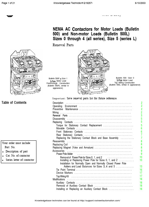
Page 1 of 21 Knowledgebase Technote # Q19257• 6/10/2003Page 2 of 21 Knowledgebase Technote # Q19257• 6/10/2003Page 7 of 21 Knowledgebase Technote # Q19257• 6/10/2003Reassembly Refer to exploded view, Figure 1, for item numbers.1. Place the movable contact support and armature assembly (item 2) in thecontactor base. Attach the contact block cover(s) and tighten screwssecurely (approximately 25 - 30 lbs.-in.).2. Insert the yoke (item 8) into the operating coil (item 7). Place theyoke-coil assembly into the contactor base. The parts are keyed to fitonly one way.3. Replace the coil cover (item 4). If used, check the tie point terminal forproper position. Tighten the coil cover screws securely (approximately25 - 30 lbs.-in.).4. With the movable contact support and armature assembly in the “OFF”position, install the auxiliary contact block(s) (item 6), if used, usinginstructions provided on the auxiliary contact block label.5.Reconnect all control wirings.Replacing CoilReplacing Magnet (Yoke and Armature)Refer to exploded view, Figure 1, for item numbers.1. Remove all wires from coil.2. Remove coil cover (item 4).Note:Auxiliary contact will come off with coil cover.3.Slide out coil (item 7) and yoke (item 8) from movable contact supportand armature assembly (item 2).4. Replace coil and reassemble with yoke.5.Slide yoke and coil back into movable contact and armature assembly.6. Reattach coil cover.7. Reattach wire to coil.8. Reattach auxiliary contact (see p. 19).Refer to exploded view, Figure 1, for item numbers.1. Always replace yoke and armature at the same time.2. Remove contact block cover (item 1), coil cover (item 4), coil (item 7),yoke (item 8), and movable contact support and armature assembly(item 2).3. Replace yoke and movable support armature assembly.4. Reassemble as previously noted.Page 10 of 21 Knowledgebase Technote # Q19257• 6/10/2003Accessories (cont’d) washers, and flat washers according to Figure 6. Tighten screws securely(approximately 16-20 lb.-in. torque).6. Place the movable contact carrier in the contactor base. Attach thecontact block covers on both the controller and the power pole adder.Tighten screws securely (approximately 25 - 30 lb.-in. torque).7. Insert the magnet yoke in the coil (see page 4). Place the yoke-coilassembly in the contactor base. The parts are keyed to fit only one way.8. Replace the coil cover. Check the tie point terminal for proper position.Tighten coil cover screws securely (approximately 25 - 30 lb.-in.)9. With the movable contact support in the “OFF” position, install theauxiliary contact block(s) according to the instructions on the auxiliarycontact block label.10. Properly reconnect all control wiring.Figure 5Right Side AssemblyAdder PoleContact CarrierMovableContactFigure 6Right Side Installation4Rectangular , Slot(Both Sides)Mtg. Screw 01A Installation for Normally Open and Normally Closed Sizes 3, 4, and 5Power Pole Adders and Load BalancersNote:When a single power pole adder (Figure 6) is added to a contactor, a load balancer (Figure 7 and Figure 8) must be added to the oppositeside of the contactor. Each kit contains one power pole adder, oneload balancer, one adder pole contact carrier, and mountinghardware. When installing two power pole adders to a singlecontactor, install a power pole adder on each side and discard loadbalancers.Load Balancer Assembly Procedure for Size 3 (See Figure 7)1. Using a screwdriver, push a special nut into the front nut pocket, makingsure that the extruded rim on the threaded hole is to the inside of thecontactor.2. Position the load balancer against the contactor base. The rectangularprojection on the load balancer fits into the rectangular slot in thecontactor base when positioned correctly. Install the two #8 - 32 X1 - 9/16" screws, lock washers, and flat washers as shown in Figure 7.Tighten screws securely (approximately 16 - 20 lb.-in. torque).Accessories (cont.)Figure 7(Size 3) Left Side InstallationPower PoleAdderReactangul a rSlotSpecial Nut, Pushed intoFront Nut PocketLoad Balancer Assembly Procedure for Size 4 and (See Figure 8)1. Using a screwdriver, push the special nuts into the nut pocket, makingsure that the extruded rims on the threaded holes are to the inside of thecontactor.2. Position the load balancer against the contactor base. The rectangularprojection on the load balancer fits into the rectangular slot in thecontactor base when positioned correctly. Install the three mountingscrews, lock washers, and flat washers according to Figure 8, using thescrew lengths specified for each position. Tighten screws securely(approximately 16-20 lb. -in. torque).Page 15 of 21 Knowledgebase Technote # Q19257• 6/10/2003Page 16 of 21 Knowledgebase Technote # Q19257• 6/10/2003Page 17 of 21 Knowledgebase Technote # Q19257• 6/10/2003Page 20 of 21 Knowledgebase Technote # Q19257• 6/10/2003 Knowledgebase technotes can be found at /Page 21 of 21 Knowledgebase Technote # Q19257• 6/10/2003 Important User Information Because of the variety of uses for the products described in this publication, those responsible forthe application and use of this control equipment must satisfy themselves that all necessary stepshave been taken to assure that each application and use meets all performance and safetyrequirements, including any applicable laws, regulations, codes and standards.The illustrations, charts, sample programs and layout examples shown in this guide are intendedsolely for purposes of example. Since there are many variables and requirements associated with anyparticular installation, Rockwell Automation does not assume responsibility or liability (to includeintellectual property liability) for actual use based upon the examples shown in this publication.Allen-Bradley publication SGI-1.1, Safety Guidelines for the Application, Installation and Maintenance ofSolid-State Control (available from your local Allen-Bradley office), describes some importantdifferences between solid-state equipment and electromechanical devices that should be taken intoconsideration when applying products such as those described in this publication.Reproduction of the contents of this copyrighted publication, in whole or part, without writtenpermission of Rockwell Automation, is prohibited.Throughout this document we use notes to make you aware of safety considerations:Identifies information about practices or circumstances that can lead topersonal injury or death, property damage or economic lossIdentifies information that is critical for successful application andunderstanding of the product.Use only replacement parts and devices recommended by Rockwell Automation to maintain theintegrity of the equipment. It is the user’s responsibility to ensure that the renewal part numberselected is properly matched to the model, series and revision level of the equipment being serviced.Servicing energized Industrial Control Equipment can be hazardous.Severe injury or death can result from electrical shock, burn, orunintended actuation of controlled equipment. Recommended practiceis to disconnect and lockout control equipment from power sources,and release stored energy, if present.Refer to National Fire Protection Association Standard No. NFPA70E, Part 2 and (asapplicable) OSHA rules for Control of Hazardous Energy Sources (Lockout/Tagout) andOSHA Electrical Safety Related Work Practices for safety related work practices, includingprocedural requirements for lockout/tagout, and appropriate work practices, personnelqualifications and training requirements where it is not feasible to de-energize and lockout or tagoutelectric circuits and equipment before working on or near exposed circuit parts.ROCKWELL DISCLAIMS ALL WARRANTIES WHETHER EXPRESSED OR IMPLIED INRESPECT TO THE INFORMATION (INCLUDING SOFTWARE) PROVIDED HEREBY,INCLUDING THE IMPLIED WARRANTIES OF FITNESS FOR A PARTICULAR PURPOSE,MERCHANTABILITY, AND NON-INFRINGEMENT. Note that certain jurisdictions do notcountenance the exclusion of implied warranties; thus, this disclaimer may not apply to you.Allen-Bradley is a trademark of Rockwell AutomationKnowledgebase technotes can be found at /。
HK系列闸刀开关的安全使用范本

HK系列闸刀开关的安全使用范本为了确保HK系列闸刀开关的安全使用,以下是使用范本,包括了必要的操作规范和注意事项。
一、设备的安装和连接1. 在进行设备的安装和连接之前,确保所有电源都已断开,并仔细阅读产品的使用说明书。
2. 使用者应该具备相关的电气知识和技能,以确保正确的设备安装。
3. 在进行安装之前,检查设备是否有任何损坏或异常,如有,应立即联系供应商或维修人员。
4. 请确保设备与电源和其他设备的连接正确无误,且连接牢固可靠。
5. 进行线路连接时,请确保操作人员本人已确切了解是否还存在电流或电压。
二、设备的操作1. 在操作前,请确保所有相关电源已关闭,并且电源线已完全断开。
2. 您应该熟悉HK系列闸刀开关的操作方法,并确保了解所有的功能和安全要点。
3. 使用者应该在操作设备时,保持冷静和集中注意力,避免分心或有其他干扰。
4. 使用HK系列闸刀开关之前,请确保开关处于关闭状态,并使用加标签的锁来锁定开关,以防止无意中开关被打开。
5. 在进行任何操作之前,请检查设备是否有损坏或异常,并确保操作杆处于正常状态。
6. 对于高电压设备,请戴上绝缘手套,以确保安全操作。
7. 在操作设备时,请始终遵循正确的步骤和顺序,确保设备在正确的状态下运行。
8. 在设备操作中,严禁将手指或其他物体放入设备内部的任何部分。
9. 操作完设备后,请将操作杆缓慢地恢复到原始位置,并关闭设备的电源。
三、设备的维护和检修1. 设备维护和检修应由经过培训和授权的人员进行。
2. 在进行任何维护和检修之前,请确保设备已断电,并完全阻止电源输入。
3. 在检修或更换设备部件时,请选择相同型号和规格的部件,并严格按照产品手册中的要求进行操作。
4. 请勿在没有特殊许可的情况下修改设备的任何部件或功能。
5. 定期检查设备的外部和内部部件,以了解是否存在任何损坏、松动或其他异常现象。
6. 在设备维护和检修过程中,经常清洁设备表面,并避免使用化学品或腐蚀性物质。
HK系列闸刀开关的安全使用范本

HK系列闸刀开关的安全使用范本一、入门指南1. 在使用HK系列闸刀开关之前,请仔细阅读并理解产品的产品手册和安全使用说明。
2. 在安装和操作闸刀开关前,请确保您已经了解和掌握相关的安全操作和维修技巧。
3. 在使用闸刀开关时,请务必遵循国家和地方的相关规定和标准,以确保使用的安全性和合规性。
4. 如果您对闸刀开关的使用和操作有任何疑问,请咨询专业人士或联系供应商寻求帮助。
二、安装和维护1. 在安装闸刀开关时,请确保工作场所干燥、通风良好,并保持清洁。
2. 按照产品手册的指示,正确连接电源和接地线路,并确保线路连接牢固可靠。
3. 安装闸刀开关时,请确保周围没有易燃物质和易燃气体,以避免火灾和爆炸风险。
4. 严禁擅自改变和调整闸刀开关的结构和参数,以免影响产品的安全性和可靠性。
5. 定期检查和维护闸刀开关,确保开关的连接和固定处于良好状态。
三、操作使用1. 在操作闸刀开关之前,务必切断电源,并确保断电状态可靠。
2. 在操作闸刀开关时,请使用专业的工具,并按照正确的工序和步骤进行操作。
3. 必须确保操作人员具有专业的电气知识和技能,并接受过相关的培训。
4. 在操作闸刀开关时,应保持手部和身体干燥,以避免电击和其他安全事故。
5. 严禁在闸刀开关上进行非授权的维修和改装,以免导致产品性能下降。
6. 使用闸刀开关时,请确保开关在工作温度和额定电流范围内,以确保产品安全可靠。
四、常见故障及处理1. 如果发现闸刀开关异常或故障,请切断电源并立即停止使用。
2. 如果闸刀开关出现异常声响或发热,请立即停止使用并联系专业人士进行检查和维修。
3. 如果闸刀开关出现漏电、电弧或其他危险情况,请立即切断电源,并采取适当的紧急措施。
4. 维修和更换闸刀开关的部件时,请使用原厂指定的配件,以确保产品安全性和性能的一致性。
五、处理废旧产品1. 废旧闸刀开关需要由经过授权的回收和处理机构进行处理,切勿随意丢弃。
2. 在废旧闸刀开关的回收和处理过程中,请遵循环保法规和相关政策,并尽量实现资源的再利用。
2024年低压防爆开关的操作(3篇)

2024年低压防爆开关的操作第1章: 引言1.1 本操作指南旨在对2024年低压防爆开关的操作进行详细说明和指导。
1.2 请在操作前仔细阅读本指南,并确保已经具备正确的操作技能和必要的安全知识。
1.3 操作者必须戴着符合规定的个人防护装备,确保操作过程中的人身安全。
第2章: 产品概述2.1 低压防爆开关是一种用于控制电路的设备,具有防爆性能。
2.2 低压防爆开关广泛应用于具有易燃、易爆等特殊环境的工业领域。
2.3 2024年低压防爆开关采用了最新的技术和材料,具有更高的耐用性和安全性。
第3章: 操作流程3.1 开关的开关操作3.1.1 在开关操作前,确保电源已经关闭并且断开电源。
3.1.2 使用专用的工具打开开关的外盖,暴露出内部的接线端子。
3.1.3 根据所需的电路连接方式,将电源线和负载线分别连接到相应的接线端子上。
3.1.4 关闭开关的外盖,并确保固定牢固。
3.1.5 打开电源,测试开关是否正常工作。
3.1.6 在开关的操作过程中,禁止用力过猛,避免造成损坏。
3.2 清洁和维护3.2.1 定期检查开关的外观和内部连接是否正常。
3.2.2 使用干净的布进行清洁,避免使用化学溶剂。
3.2.3 定期检查开关的操作灵活度,如有异常应及时更换。
3.2.4 不得私自拆卸或更换开关内部零件,避免损坏导致安全隐患。
第4章: 安全注意事项4.1 操作者必须定期接受安全培训,掌握正确的操作方法和紧急处理措施。
4.2 操作前必须检查开关是否处于断电状态,确保人身安全。
4.3 在操作过程中,如发现开关有异常或故障,应立即停止操作,并联系专业人员进行维修处理。
4.4 操作者应随时关注周围环境,确保操作过程中没有明火或其他可能引发爆炸的危险物。
4.5 禁止在开关操作过程中使用手机或其他电子设备,以免造成电路干扰或其他意外事故。
第5章: 故障处理5.1 如发现开关无法正常工作或出现故障,应立即切断电源,并联系专业人员进行维修处理。
安全开关AZM 161 Z ST1-AS RA说明书

25.10.2016 10:35:58hDatasheet AZM 161 Z ST1AS RAAS interface safety at work / Safety switchgear / Solenoid interlock / AZM 161ASPreferred typ(Minor differences between the printed image and the original product may exist!)• Solenoid interlock• Thermoplastic enclosure • High holding force 2000 N • 130 mm x 90 mm x 30 mm• Interlock with protection against incorrect locking.• Doubleinsulated • Long life• Integrated ASInterface• Solenoid supply aus AS interface • Guard locking monitored • Manual releaseOrdering detailsProduct type description AZM 161 Z ST1AS RA Article number 101209104EAN code 4030661396477eCl@ss 27272603ApprovalApprovalASiTÜV USA/CANClassificationStandards EN ISO 138491, IEC 61508PLup c Control category 1PFH 1.14 x 10⁶ / h notice up to max. 100.000 switching cycles/year SIL up 1Mission time20 Y earsIf a fault exclusion for hazardous damage of the 1channel mechanics is authorized and an adequate protection against tampering is ensured, suitable for use up to:Standards EN ISO 138491, IEC 61508PLup d Control category 3PFH value 1.01 x 10⁷ / h notice up to max. 100.000 switching cycles/year SIL up 2Mission time20 Y earsGlobal PropertiesProduct name AZM 161 ASStandards EN 50295, EN 6094751, IEC 61508, EN ISO 138491 Compliance with the Directives (Y/N) Y esNumber of actuating directions3 pieceActive principle electromechanicalDuty cycle Magnet 100 %Materials Material of the housings Plastic, glassfibre reinforced thermoplastic, selfextinguishingHousing coating NoneWeight465 gGuard locking monitored (Y/N)Y esActuator monitored (Y/N)NoResponse time< 100 msMechanical dataActuating play in direction of actuation 5.5 mmDesign of electrical connection connector plug M12, 4poleconnector bottomMechanical life> 1.000.000 operationsrestistance to shock30 g / 11 msResistance to vibration10 Hz ... 150 Hz, Amplitude 0,35 mmEmergency unlocking device (Y/N)NoManual release (Y/N)Y esEmergency release (Y/N)NoLatching force30 NClamping force F2000 NMax. Actuating speed2 m/sActuating frequency max. 1000 / hAmbient conditionsAmbient temperature Min. environmental temperature−25 °C Max. environmental temperature+60 °CStorage and transport temperature Min. Storage and transport temperature−25 °C Max. Storage and transport temperature+85 °CRelative humidity30 % ... 95 % noncondensingProtection class IP67 to IEC/EN 60529Protection rating IIAir clearances and creepage distances To IEC/EN 606641 Rated impulse withstand voltage U imp0,8 kV Rated insulation voltage U i32 VDC Overvoltage category III Degree of pollution3Electrical dataPower to unlock NoPower to lock Y esElectrical data AS interfaceASi Supply voltage26.5 ... 31.6 VDC, Protection against polarity reversalASi operating current≤ 250 mAASi Device insulation internally shortcircuit proofASi Specification version V 2.1 Profile S7.B.F.E IOCode0x7 IDCode0xB IDCode10xF IDCode20xEASi Inputs Channel 1Data bits DI 0/DI 1= dynamic code transmission Channel 2Data bits DI 2/DI 3= dynamic code transmissionASi Outputs DO 0Solenoid control DO 1not used DO 2not used DO 3not usedASi Parameter bits P0Actuator detected P1Solenoid interlock locked P2magnet voltage in tolerance range P3error message locking/unlocking of the solenoid interlockblockedASi input module address0 Default on address 0, programmable via the ASInterface Master or Handheld programming deviceLED switching conditions displayLED switching conditions display (Y/N)Y esASi LED switching conditions display(1) yellow LED Channel 2 / ASi SaW Bit 2,3(2) green/red LED (ASi duo LED)Supply voltage / Communication error / slave address = 0or periphery error(3) yellow LED Channel 1 / ASi SaW Bit 0,1ATEXExplosion protection categories for gases NoneExplosion protected category for dusts NoneMiscellaneous dataApplicationssliding safety guard,removable guard,hinged safety guardDimensionsDimensions of the sensor Width of sensor130 mm Height of sensor90 mm Length of sensor30 mmPin assignment1ASi +2Aux − (P)3ASi −4Aux + (P)noticeInterlocks with power to lock principle may only be used in special cases after a thorough evaluation of the accident risk, since the guarding device can immediately be opened on failure of the electrical power supply or when the main switch is opened.Manual release• For maintenance, installation, etc.• For manual release using M5 triangular key, available as accessoryIncluded in deliveryActuators must be ordered separately.Ordering codeAZM 161 (1) (2)AS (3)(4)(5)(6)(1)Z Guard lockingmonitoredB Actuator monitoredBZ(2)ST1Connector bottomST2Connector right(3)without Latching force 5 NR Latching force 30 N(4)without Power to unlockA Power to lock(5)without Solenoid supply ausAS interfaceP Solenoid supply aus24 VDC (Aux)(6)without Manual releaseN Emergency releaseT Emergency exitDocumentsOperating instructions and Declaration of conformity (en) 569 kB, 12.03.2010Code: mrl_azm161as_enOperating instructions and Declaration of conformity (it) 493 kB, 15.03.2010Code: mrl_azm161as_itOperating instructions and Declaration of conformity (es) 495 kB, 16.03.2010Code: mrl_azm161as_esOperating instructions and Declaration of conformity (pl) 319 kB, 11.02.2015Code: mrl_azm161as_plOperating instructions and Declaration of conformity (de) 572 kB, 12.03.2010Code: mrl_azm161as_deOperating instructions and Declaration of conformity (fr) 485 kB, 15.03.2010Code: mrl_azm161as_frOperating instructions and Declaration of conformity (jp) 712 kB, 14.11.2011Code: mrl_azm161as_jpOperating instructions and Declaration of conformity (nl) 478 kB, 15.03.2010Code: mrl_azm161as_nlBGtest certificate (de, en) 286 kB, 01.06.2010Code: z_161p01ImagesDimensional drawing (basic component)Contact arrangementOperating principleSystem componentsActuator101145117 AZM 161B1101144416 AZM 161B1E101171859 AZM 161B1ES101175431 AZM 161B1F101171125 AZM 161B1S101173089 AZM 161B12053 WITH BALL LATCH101164100 AZM 161B11747 WITH MAGNETIC LATCH101178199 AZM 161B12024101176642 AZM 161B12177 WITH CENTERING GUIDE101174113 AZM 161B62177 WITH CENTERINGGUIDE• For very smal actuating radii101170375 AZM 161B6S101144420 AZM 161B6• For very smal actuating radiiDoorhandle systemAZM 161STS30• Latching handle• Suitable for all types of guard• einsetzbar in Verbindung mit EXAZM 161suitable in combination with #01#Accessories101100887 TRIANGULAR KEY TKM5• For manual release using M5 triangular key, available asaccessory• For maintenance, installation, etc.K.A. Schmersal GmbH & Co. KG, Möddinghofe 30, D42279 WuppertalThe data and values have been checked throroughly. Technical modifications and errors excepted.Generiert am 25.10.2016 10:35:59h Kasbase 3.2.5.F.64I。
断路器(MCB)8530 1-MCB系列使用说明书
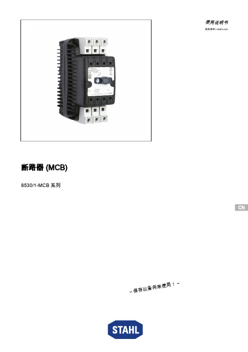
CN CN CN CN CN CN CN CN CN CN CN CN CN CN CN CN CN CN CN CN CN CN CNCN使用说明书其他语种 断路器 (MCB)8530/1-MCB 系列– 保存以备将来使用! –内容目录1总体说明 (3)1.1制造商 (3)1.2关于本使用说明书 (3)1.3其他文档 (3)1.4标准和规定的符合性声明 (3)2符号说明 (4)2.1本使用说明书中的符号 (4)2.2设备上的符号 (4)3安全 (5)3.1设计用途 (5)3.2人员资格 (5)3.3残余风险 (6)4运输和仓储 (7)5产品选择、项目设计和修改 (7)5.1项目设计 (7)6安装与装配 (8)6.1安装/拆卸 (8)6.2装配 (10)7调试 (11)8运行 (11)8.1操作 (11)9维护,翻新,修理 (12)9.1维护 (12)9.2翻新 (12)9.3修理 (12)10退回 (13)11清洁 (13)12弃置处理 (13)13配件和备件 (13)14附录 A (14)14.1技术数据 (14)15附录 B (24)15.1设备设计 (24)15.2尺寸信息/固定尺寸 (25)2断路器 (MCB)8530/1-MCB 系列292024 / 853********* 2023‐07‐03·BA00·III·zh·03总体说明3断路器 (MCB)8530/1-MCB 系列1总体说明1.1制造商R.STAHL Schaltgeräte GmbHAm Bahnhof 3074638 Waldenburg德国电话:+49 7942 943-0传真:+49 7942 943-4333网址:电子邮箱:****************1.2关于本使用说明书❝在使用前必须认真阅读本使用说明书,尤其是安全注意事项。
❝注意所有随附文档(也请参见第 1.3 章)❝在设备使用周期内请保留本手册。
【推荐】使用开关说明书-推荐word版 (12页)
本文部分内容来自网络整理,本司不为其真实性负责,如有异议或侵权请及时联系,本司将立即删除!== 本文为word格式,下载后可方便编辑和修改! ==使用开关说明书篇一:压力开关操作说明书CN CN目录1 说明 1.1 重要说明 1.2 开关标识 2 探测头安装 2.1 压力与真空探测头2.2 差压探测头 2.3 温度探测头3 封装外壳的安装 3.1 “C”型外壳 3.2 “Z”型外壳 3.3 “V”型和“W”型外壳3.4 “M”型外壳 4 电气安装5 设定点调节6欧共体标准符合说明1 说明1.1 重要说明 * * * * * * * * * * * * *BETA压力开关属于精密仪器请正确放置或搬动。
BETA压力开关在达到设定点的(差压)压力或者温度时开关动作。
在按照说明书指示正确安装,该开关的设计与结构是完全免维护的。
切莫采用液态油或油脂润滑开关的任何部件。
除了更换外壳密封与安装支架外,不要移动或更换本开关的任何部件。
避免暴露在超高温、超低温、有侵蚀性环境中,-30~80℃为适宜温度。
调节螺丝有自锁性,所以在调节设定点后禁止封死调节螺丝。
安装前请详细检查铭牌上数据。
所有尺寸均以mm毫米标注。
如果您需要帮助请与供应商联系,开关只有在去污清洗后才能进行维护检修。
如果您需要额外的膜片O形圈和微动开关,请给出序列号向供应商购买。
开关的检修维护请由专业的仪表工程师实施。
除了更换膜片O形圈和微动开关以外,其它形式的检修维护有厂方执行。
非厂方检修维护的操作会影响产品本身的质量保证。
本章节的指导说明书的步骤也是安装步骤说明。
地基与工程环境的强烈振动可能会影响开关的正常功能。
1.2 开关标识压力开关的铭牌上面标明了规格型号,4到7步可以确定该压力开关的设计组成,后缀的X+数字来表明特殊要求,该特殊要求可参照数据书。
外壳封装C1-P304L-S1N-B1-K1-Y-X2第一个字符即第一步标明了外壳封装形式:C、V、W、Z或M,参照图1-4和15。
GE的一般用途安全开关说明说明书

34578GE’s general duty safety switches are available in 30-600 amps, 240 Vac, 250 Vdc maximum in both fusible and non-fusible units, and in NEMA Type 1 (indoor) and Type 3R (outdoor) enclosures. The UL Listed short-circuit rating is 10,000 rms symmetrical amps as standard. When Class R fuses and fuse kits are installed, 30-200 amp switches have a UL Listed short circuit rating of 100,000 rms symmetrical amps. GE’s general duty safety switches are UL Listed as service entrance equipment when installed in accordance with the National Electrical Code.All GE General Duty safety switches carry the following certifications:• UL Listed and cUL Listed (UL98 Enclosed Switches/CSA-C22.2 No. 4-04) • Federal Specification WS-865C• NEMA Enclosed Safety Switch Standard KS1-2013 •Seismic CertifiedFeatures12660A/Fusible/3 Pole/240V/N1TG4322Highly visible ON/OFF labelHighly visible, easy to grip red handle andaccepts 1 padlock in the OFF position Direct-drive, quick-make, quick-breakmechanism "snaps" contacts open and closed providing positive ON/OFF indication Unobstructed gutterSelf-leveling, three-point mounting system Integral cover interlockVisible confirmation of plated bladecontact positions Spring reinforced fuse clips assure reliablecontact for cool operation. Suitable for Class H, K or R fuses, where applicable12345678SafetyEase of Installation and MaintenanceGeneral Duty Safety Switch Short Circuit RatingsMaximum System Voltage Ampere RatingUL Listed Fusing Enclosure TypeClassWithstand Rating (rms Sym Amps)Fusible240 Vac250 Vdc30-600K 10,000N1N3RH 10,000R 1100,000Non-Fusible: Fuse withstand ratings apply to non-fused switches when protected by an upstream fuse as listed240 Vac 250 Vdc 30-600No upstream protection 10,000N1N3R K upstream 10,000H upstream 10,000R upstream 100,0001Class R fuse is not available for 400A or 600A General Duty switches.Lug Wire Sizes Line and Load TerminalsAmpere Rating Wire Range AWG/kcmil Copper Wire RangeAWG/kcmil Aluminum 30A (250V)14-812-830A (600V)12-212-260A 12-212-2100A 10-1/010-1/0200A 2-2502-250400A (1) 2-800 or (2) 1/0-250(1) 2-800 or (2) 1/0-250600A(2) 4-500(2) 4-50060A/Fusible/ 3 Pole/240V/N1TG4322100A/Non-Fusible/3 Pole/240V/ N3RTGN3323R30A/Non-Fusible/3 Pole/240V/ N3RTGN3321R23460A/Fusible/3 Pole/240V/N1TG4322VREDSafety Switch Enclosure DimensionsProduct Number Dimension H Dimension W (Box)Dimension W 2 (W/ Handle)Dimension D (Box)DimensionD 2 (W/ Handle)Weight(lbs)Drawing #KO Figure NumberTG322110.3 6.4 6.9 3.3 6.3510103091SH1041TG3221VRED 10.3 6.4 6.9 3.3 6.3510103091SH1041TG322213.88.48.9 4.07.91010103091SH10415TG322321.39.410.6 4.99.91610103091SH1083TG322429.113.414.6 5.29.33010103091SH1084TG3224B 29.113.414.6 5.29.33010103091SH1084TG322549.421.622.88.714.610210103091SH1165TG3225B 49.421.622.88.714.610210103091SH1165TG322649.922.924.19.014.810710103091SH1166TG332549.421.622.88.714.610710103091SH1167TG3325B 49.421.622.88.714.610710103091SH1167TG332649.922.924.19.014.812410103091SH1166TG3326B 49.922.924.19.014.812410103091SH1166TG432110.3 6.4 6.9 3.3 6.3510103091SH1041TG4321VRED 10.3 6.4 6.9 3.3 6.3510103091SH1041TG432213.88.48.9 4.07.91010103091SH10415TG4322VRED 13.88.48.9 4.07.91010103091SH10415TG432321.39.410.6 4.99.91710103091SH1083TG432429.113.414.6 5.29.33210103091SH1084TG4324B 29.113.414.6 5.29.33210103091SH1084TG432549.421.622.88.714.611110103091SH1167TG4325B 49.421.622.88.714.611110103091SH1167TG432649.922.924.19.014.812610103091SH1166TG4326B 49.922.924.19.014.812610103091SH1166TGN332110.3 6.4 6.9 3.3 6.3510103091SH1041TGN332213.88.48.9 4.07.91010103091SH10415TGN332321.39.410.6 4.99.91610103091SH1083TGN332429.113.414.6 5.29.33010103091SH1084TGN3324B 29.113.414.6 5.29.33010103091SH1084TGN332549.421.622.88.714.611810103091SH1167TGN3325B 49.421.622.88.714.611810103091SH1167TGN332649.922.924.19.014.812010103091SH1166TGN3326B49.922.924.19.014.812010103091SH1166Product Number Dimension H Dimension W (Box)Dimension W 2 (W/ Handle)Dimension D (Box)DimensionD 2 (W/ Handle)Weight(lbs)Drawing #KO Figure NumberTH2261DC 12.68.39.5 4.07.61110103091SH10215TH2262DC 21.39.19.4 5.08.61810103091SH1023TH2263DC 22.39.310.1 4.89.81910103091SH105 14TH322110.3 6.37.1 3.3 6.1610103091SH1021TH322217.69.410.1 5.09.01510103091SH1023TH322321.39.310.1 4.89.81710103091SH1053TH322431.513.314.1 5.110.53310103091SH1054TH3224B 31.513.314.1 5.110.53310103091SH1054TH3224C 31.513.314.1 5.110.53310103091SH1054TH322550.922.923.68.314.412010103091SH1126TH3225B 50.922.923.68.314.412010103091SH1126TH3225C 50.922.923.68.314.413510103091SH1126TH322650.922.923.68.314.413410103091SH1126TH3226B 50.922.923.68.314.413410103091SH1126TH3226C 50.922.923.68.314.413410103091SH1126TH3267C 61.540.844.011.918.550010103091SH1126TH3268C 76.646.645.812.918.948010103091SH1126TH332550.922.923.68.314.412610103091SH1126TH3325B 50.922.923.68.314.412610103091SH1126TH332650.922.923.68.314.413810103091SH1126TH3326B 50.922.923.68.314.413810103091SH1126TH336112.68.39.5 4.07.61110103091SH10215TH336221.39.19.4 5.08.61810103091SH1023TH336322.39.310.1 4.89.81810103091SH10514TH336431.513.314.1 5.110.53310103091SH1054TH3364B 31.513.314.1 5.110.53410103091SH1054TH336553.922.923.68.314.412610103091SH1126TH3365B 53.922.923.68.314.412210103091SH1126TH336653.922.923.68.314.413910103091SH1126TH3366B 53.922.923.68.314.413910103091SH1126TH432110.3 6.37.1 3.3 6.1610103091SH1021General Duty, NEMA Type 1 Approximate Dimensions in inchesHeavy Duty, NEMA Type 1 Approximate Dimensions in inches(table continued on next page)General Duty NEMA Type 1Heavy Duty NEMA Type 1HHGeneral Duty NEMA Type 3RHeavy Duty NEMA Type 1Heavy Duty NEMA Type 3RGeneral Duty NEMA Type 1D Heavy Duty NEMA Type 1General Duty NEMA Type 1Safety Switch Enclosure DimensionsHeavy Duty NEMA Type 3R Side SwingNEMA Type 3R 200-600A Side SwingSafety Switch KnockoutsSymbol A B C D E F G H J K L M NConduit Size (Inches)9/321/21/21/21/21/23/43/41122 2 1/2––3/43/43/43/411 1 1/4 1 1/2 2 1/2 2 1/23–––111– 1 1/4 1 1/2233––––– 1 1/4 1 1/2– 1 1/22 2 1/2– 3 1/2–Dimensions—KnockoutsFigure 1Figure 2 Figure 3Figure 4Figure 5Figure 6Figure 7 Figure 8Figure 9Figure 10Figure 11Figure 12 Figure 13Figure 14Figure 15Figure 16 Figure 17Figure 18Figure 19Figure 20GE41 Woodford Avenue Plainville, CT 06062 1-800-431-7867 *Indicates a trademark of the General Electric Company and/or its affiliates.Information provided is subject to change without notice. Please verify all details with GE. All values are design or typical values when measured under laboratory conditions, and GE makes no warranty or guarantee, express or implied, that such performance will be obtained under end-use conditions.©2018, General Electric Company and/or its affiliates. All rights reserved.8.18 DET-845-GEN。
- 1、下载文档前请自行甄别文档内容的完整性,平台不提供额外的编辑、内容补充、找答案等附加服务。
- 2、"仅部分预览"的文档,不可在线预览部分如存在完整性等问题,可反馈申请退款(可完整预览的文档不适用该条件!)。
- 3、如文档侵犯您的权益,请联系客服反馈,我们会尽快为您处理(人工客服工作时间:9:00-18:30)。
选择触发块
注意 使用不合适的触发块会导致设备损坏。务必选择 正确的触发块(请参见图2中的表)。 另外,请注意门半径和固定选件(请参见图4)。
以下型号可供选择: ffS触发块,用于不带插接筒的安全开关 ffL触发块,用于带插接筒的安全开关
手动解锁
在某些情况下,需要手动解锁门锁装置(例如发 生故障或紧急情况下)。解锁后应执行功能测试。 有关本主题的更多信息,请参见标准 EN ISO 14119:2013的第5.7.5.1部分。设备可以 具有以下解锁功能:
通过弹簧操作的门锁装置按照通电解锁原理进行
ffEN 60204‑1,机械安全 - 机器的电气设备。
工作。当电磁线圈断电时,门锁装置将保持启用
注意
状态,但不能直接打开安全门。
ff用户负责将设备正确集成到整个安全系统之 中。为此,必须依据EN ISO 13849‑2等要求对 整个系统进行验证。
若在断电时安全门处于打开状态,再次关闭安全 门将会启用门锁装置。这可能造成人员被意外 锁在门内。
如果凸轮处于锁止状态(即门锁装置启用),则无 法将触发块从开关触头中拔出。出于设计原因,只 有在安全门关闭的情况下才能启用门锁装置(故障 安全锁止机制)。
对此安全开关进行了设计,可假设针对内部故障 的故障排除符合EN ISO 13849‑2:2013的表A4。
本系列设备也适用于过程保护。
门锁状态监控
所有型号都至少配有一个用于监控门锁装置的安 全触点。当门锁装置解锁时,触点 即会打开。
门监控触点
型号STA3和STA4至少额外配有一个门监控触 点。视开关元件而定,门监控触点可以是强制动 作触点(触点 ),也可以不是强制动作触点。 当安全门打开时,门监控触点即会触发。
正确使用包括遵守相关的安装和操作要求,尤其 是基于以下标准的要求:
ff危险的机器功能结束之前,不得解锁门锁装置。
ff安全门的关闭和锁止不得引发危险的机器功能 自动启动。必须发出单独的启动命令才能启动 危险功能。例外情况请参阅EN ISO 12100或相 关C标准。
功能
安全开关可将移动式安全门锁止。
开关触头内有一个旋转凸轮,此凸轮通过锁止销 钉锁止/解锁。
插入/拆除触发块以及激活/解锁门锁装置时, 锁止销钉即会移动。在此过程中,开关触点被 触发。
STA1和STA3型号
ffEN ISO 13849‑1,机械安全 – 控制系统安全相 (弹簧力锁止,通电解锁)
关部件 – 第1部分:设计通则
ff启用门锁装置:关闭安全门,电磁线圈未通电
ffEN ISO 14119,机械安全 – 与防护门关联的互 ff解锁门锁装置:电磁线圈通电
锁装置 – 设计及选型原则
钉并进行密封(例如漆封)。
应急逃生解锁装置
借助此装置,无需任何工具即可从危险区域将已 锁止的安全门打开。 注意 ff必须能够在不使用任何工具的情况下从受保护
区域内部手动触发应急逃生解锁装置。 ff不得从外部触及应急逃生解锁装置。 ff手动解锁期间,触发块不得承受拉力。 ff应急逃生解锁装置满足EN ISO 13849‑1:2015类
安全门关闭但未锁止
小心
在高于40 °C的环境温度下,高温壳体可能会 导致危险。
ff对开关采取保护措施,以防人员接触或与易 燃材料接触。
STA1和STA2:f 安全触点 打开。 STA3和STA4:f 安全触点 闭合。安全触点
安全门关闭且已锁止
打开。
STA1和STA2:f 安全触点 闭合。
STA3和STA4:f 安全触点 和 闭合。
使用设备前,必须依据下列标准对机器执行风 险评估:
ffEN ISO 13849‑1,机械安全 – 控制系统安全相 关部件 – 第1部分:设计通则
ffEN ISO 12100,机械安全 – 设计通则 – 风险评 估和风险降低
ffIEC 62061,机械安全 – 与安全有关的电气、电 子和可编程电子控制系统的功能安全。
安全注意事项
警告
安装不当或旁路(改动)可能造成生命危险。 安全部件用于执行人员保护功能。
ff不得将安全部件旁通、转向一侧、拆除或以 其他方式使之失效。在本主题中,请特别注 意EN ISO 14119:2013第7部分中有关减小旁 路可能性的措施。
STA2和STA4型号
(通电锁止,弹簧力解锁) 注意 只有在特殊情况下,在经过严格的事故风险评 估(参见EN ISO 14119:2013第5.7.1部分)后, 才能将该开关用作人员保护门锁装置! ff启用门锁装置:关闭安全门,电磁线圈通电 ff解锁门锁装置:电磁线圈未通电 通过磁力锁闭的门锁装置按照断电解锁原理进行工 作。当电磁线圈断电时,门锁装置将解锁,可以直 接打开安全门!
ff如果采用 EN ISO 13849‑1:2015第6.3部分中 所述的简化方法来确定性能等级(PL),则在多 个设备串联的情况下PL可能减小。
ff在某些情况下,安全触点逻辑串联时性能等级 最大可达到PL d。ISO TR 24119中提供了相关 的详细信息。
ff如果产品附有数据表,则当数据表中的信息与 使用说明书不符时,请以数据表为准。
使用说明书 安全开关 STA…
正确使用
STA系列安全开关是配有门锁电磁线圈(独立触 发块)的互锁装置。触发块具有的编码等级较 低。本安全部件与移动式安全门和机器控制系统 配合使用,可防止安全门在执行危险的机器功 能时打开。
这意味着:
ff只有在安全门关闭并锁止的情况下,才能启用 可触发危险机器功能的启动命令。
机械式解锁装置
如果出现故障,无论电磁线圈处于何种状态,均 可用机械式解锁装置解锁门锁装置。 当机械解锁式装置触发后,触点 即会打开。必 须使用这些触点生成停止命令。
触发机械式解锁装置 1. 拧下锁止螺钉。 2. 用螺丝刀沿箭头方向将机械式解锁装置转动
至。 ¨¨ 门锁装置即会解锁。 注意 ff手动解锁期间,触发块不得承受拉力。 ff使用后复位机械式解锁装置,然后拧入锁止螺
开关状态
有关开关的详细开关状态,请参见图3。其中对所 有可用的开关元件进行了介绍。
安全门开启
ff开关操作必须通过专用的触发块触发。
ff借助备用触发块防止旁路。为此,请限制人员 触碰触发块和解锁装置钥匙。
ff安装、电气连接和设置工作只能由具备安全 部件处理方面专业知识的授权人员来执行。
STA1和STA2:f 安全触点 打开。 STA3和STA4:f 安全触点 和 打开。