热风炉控制系统中英文对照外文翻译文献
热风炉中英文说明书

JDK型空气加热器(热风炉)使用说明书Operation Manual of JDKType Air Heater常州市鼎龙环保设备有限公司常州市鼎马干燥机械有限公司Changzhou Dinglong Environmen Protection Equipment Co., Ltd.Changzhou Dingma Drying Machinery Co., Ltd.二00八年敬告用户Notice抽板式链条炉排调风和清灰系统为一体。
Air regulation and dust cleaning system of drawerpanel-type chain grate is a whole.操纵拉杆每2小时往复拉动清灰后复位至需要的风门开度,切记!!!After reciprocating pull and dust cleaning every 2 hours, please reset the control operating rod, and ensure the properopening of the throttle. DO REMEMBER!!!CONTENT1. 概述Summary (1)2. 结构性能简介Brief Introduction of Structural Performance (2)3. 系统图及说明System Drawing and Explanation (3)4. 点火及启动Ignition and Starting (4)5. 烘炉Heat furnace (5)6. 正常运行Normal Operation (6)7. 链条炉排的运行操作和调节Operation and Adjustment of Chain Grate (7)8. 设备保护Protection of the Equipment (12)9. 系统清灰及清渣Dust Cleaning and Slag Removal for the System (13)10. 停炉Shutdown of the Stove (14)11. 维护和保养Maintenance (15)12. 附:沉降室热风炉的清灰 (17)Appendix: dust cleaning of hot blast stove with settling chamber (17)1.概述SummaryJDK系列空气加热器(也称热风炉)是一种以煤为燃料,以空气为介质的新型高效的换热设备,能连续提供恒温、恒压、无尘的干净热空气,广泛应用于纺织漂染、橡胶涂层的热定型;印铁涂料烘房、金属表面除锈处理后的烘干及油漆烘干,造纸工业的烘干,粮食饲料、谷物鱼粉、烟叶茶叶等的烘干;胶合板、石膏板的成型干燥,木材干燥,化工物料、动植物油脂的喷雾干燥以及工业厂房的采暖等等。
热风炉控制系统中英文对照外文翻译文献

热风炉控制系统中英文对照外文翻译文献(文档含英文原文和中文翻译)译文:基于西门子PCS7的热风炉控制系统的设计本文介绍的方法利用西门子过程控制系统PCS7 V6.0控制加热炉。
描述了两者的配置控制系统软件和硬件,功能通过该系统,随着困难解决方案。
加热炉控制系统的配置双CPU冗余。
采用工业以太网,欧洲流行的PROFIBUS DP现场总线和分布式I / O减反射膜结构。
它采用ET200M I/O站的冗余。
带PROFIBUS-DP通信接口和节点具有双控制器的通信协议(CPU)。
一、介绍在生产过程中的热轧带钢,要求对来料板坯温度比较高;一般来说,应当是1 350℃左右。
的加热炉的加热程序的设备,如能满足连续可靠的要求生产只有在控制的温度和输出量有很好的协调。
加热炉采用可移动的步进梁移动冷板坯的出口侧的输入时,炉侧;钢板坯是移动的,它将被加热的喷嘴喷射炉气联合焦炭炉。
当板坯入炉炉体的末端,它首先会被加热到850℃左右在预热段,然后约1300℃在加热段;最后将进入热浸泡部分使板坯加热均匀滚动。
上述控制过程通常通过不断的PID (比例,积分和差分)。
S分别对各控制截面的顶部或侧壁分别收集实际温度在每节该炉和再采样值将被发送到PLC(可编程逻辑控制器)实现连续比例,积分和微分(PID控制)通过测量值之间的差异空气和煤气流量设定值;然后开度每段的喷枪将调整控制气体的流量,温度控制,然而,因为它不是关于气体的燃烧清楚,如果这采用的方法是,热利用效率介质的极低、能耗非常大。
在这里,一种改进的双交叉振幅限制全自动燃烧控制进行了介绍和其基本原理是进行控制燃烧的上部和下部各节在正常工作时间;如有必要,温度将上部调整信号可被视为套双交叉限幅控制和在下部前温度检测值可用于炉状态监测。
这一原则主从控制模式可以更好地协调在上燃烧和供热平衡段和下部的燃烧上、下段均匀;同时,它认为天然气的燃烧,起到了很好的作用节能。
在这个项目中,PCS7 V6.0由西门子将用于实现上述控制功能。
高炉炼铁用设备材料词汇中英文翻译对照表

区域A (For Area A)Sector 段CISDI CodeCISDI代码Description 名称English 英文A BF 高炉本体Blast Furnace ProperB HS 热风炉Hot StoveC SW 软水回路Soft Water CircuitD CA 出铁场Cast HouseE ST 水渣系统Slag Granulation SystemF GC 煤气清洗系统Gas Cleaning SystemG SH 原料贮运系统Raw Material Handling SystemH 电气自动化和仪表-公用部分Electrical Automation & Instrumentation - CommonIJK CI PCI Pulverized Coal InjectionL OE 富氧系统Oxygen Enrichment SystemM CM 电讯和ITV系统Communication & ITV SystemN AC 空调系统Air Conditioning SystemO FF 消防及火灾报警系统Fire Fighting & DetectionSystemP CS 土建和钢结构厂房Civil & Metallic StructuresBuildingQ UT 公辅和操作支持系统Utilities & Operation SupportSystemZ EA 概述General区域D (For Area D)B RT TRT 系统Turbine Recovery TopK IW 高炉净环水处理厂Indirect Water Treatment Plant区域A (For Area A)A-高炉本体..................................................................................................................... BF Proper1. 安全水塔出水管手动阀manual valve for outlet pipe of safety water tower2. 安全水塔出水管止回阀check valve for outlet pipe of safety water tower3. 安全水塔气动阀pneumatic valve for safety water tower4. 安全水塔手动阀manual valve for safety water tower5. 泵出口电动阀motorized valve at outlet of pump6. 泵出口伸缩节retractable joint at outlet of pump7. 泵出口手动阀manual valve at outlet of pump8. 泵出口止回阀check valve at outlet of pump9. 泵进口手动阀manual valve at inlet of pump10. 便携式超声波流量计............................................................... p ortable ultrasonic flowmeter11. 变频电机,变频调速电机VVVF motor12. 并罐无料钟炉顶 ........................................................................parallel-hopper bell-less top13. 波纹补偿器 .......................................................................................... bellowscompensator14. 波纹管....................................................................................................................... bellows15. 补水电动阀 ................................................................... motorized valve for water make-up16. 补水手动阀 ....................................................................... manual valve for water make-up17. 不锈钢手动球阀 .............................................................. m anual stainless steel ball valve18. 布料溜槽distribution chute19. 超微孔炭砖super micro-porous carbon blocks20. 超越冷却塔手动阀overriding manual valve for cooling tower21. 称量料罐weighing hopper22. 齿轮箱.....................................................................................................................gear Box23. 出铁口....................................................................................................................... taphole24. 除尘器氮气吹扫阀N2 purging valve for deduster25. 除尘器蒸汽吹扫阀 ........................................................... steam purging valve for deduster26. 传动齿轮箱transmission gearbox27. 大炭砖carbon blocks28. 单轨小车........................................................................................................... monorail car29. 氮化硅结合碳化硅砖Si3N4-SiC brick30. 倒流休风管 ................................................................................................... back draft pipe31. 捣打料ramming material32. 电动蝶阀........................................................................................ m otorized butterfly valve33. 斗式提升机pocket elevator34. 二冷 ......................................................................................................... s econdary cooling35. 防水耐火泥浆.................................................................................... water-proof fire mortar36. 风口 ............................................................................................................................ tuyere37. 风口大套tuyere holder38. 风口小套tuyere39. 风口中套tuyere cooler40. 风口组合砖tuyere assembly41. 刚玉质泥浆corundum mortar42. 刚玉砖corundum brick43. 高架蓄水池 .............................................................................................. elevated reservoir44. 高炉低压供水泵low-pressure water pump for BF45. 高炉高压柴油机供水泵diesel pump for BF high-pressure water46. 高炉高压供水泵high pressure water pump47. 高炉回水提升泵lifting pump for BF return water48. 高炉软水二冷水供水泵secondary cooling water pump for BF soft water system49. 工业循环水 .............................................................................. industrial recirculating water50. 供水和回水主管 ................................................................... water supply and return mains51. 管道过滤器pipe filter52. 光面冷却壁flatstave53. 滑轮pulley54. 缓冲耐火泥浆amortization fire mortar55. 灰铸铁冷却壁......................................................................................... g ray cast iron stave56. 回声探测器sound detector57. 加速仪accelerometer58. 间接循环水冷却塔indirect recirculating water cooling tower59. 浇注料castable60. 接受罐receiving tank61. 截止阀................................................................................................................ check valve62. 金属软管............................................................................................................. metal hose63. 进冷却塔手动阀manual valve for cooling tower inlet64. 净环水indirect recirculating water65. 卷扬机................................................................................................................. hoist winch66. 客货两用电梯cargo-passenger dual-purpose elevator67. 雷达式探尺 .................................................................................................... r adarstock rod68. 冷却壁.......................................................................................................................... stave69. 冷却壁设备配置 ...................................................................................... s tave configuration70. 冷却壁镶砖stave Inlaid brick71. 冷却循环泵cooling circulating pump72. 冷水池......................................................................................................... c old water basin73. (高炉)利用系数productivity of BF74. 炉底 ..................................................................................................................... BF bottom75. 炉底保护砖protection brickfor BF bottom76. 炉底冷却设备.................................................................... c ooling equipment for BF bottom77. 炉底铺设梁及水冷管beam and water pipe for BF bottom78. 炉底水冷管 ........................................................................................................ b ottom Pipe79. 炉顶氮气吹扫阀BF top N2 purging valve80. 炉顶结构..................................................................................................... BF top structure81. 炉顶均排压设备 ....................................... BF top pressure equalizing and relief equipment82. 炉顶框架.......................................................................................................... BF top tower83. 炉顶喷水BF top water spray84. 炉顶平台...................................................................................................... BF top platform85. 炉顶人孔BF top manhole86. 炉顶洒水装置BF top sprinkling device87. 炉顶探尺..................................................................................................... B F top stock rod88. 炉顶外封罩 ....................................................................................................... BF top cone89. 炉顶循环水系统 .......................................................... recirculating water system for BFtop90. 炉顶液压站和润滑站.................................. hydraulic stationandgreasing station for BF top91. 炉顶蒸汽吹扫阀steam purging valvefor BF top92. 炉腹 .............................................................................................................................. bosh93. 炉腹用铝炭砖aluminum-carbon brick for bosh94. 炉缸 ............................................................................................................................ h earth95. 炉喉 ............................................................................................................................. t hroat96. 炉喉保护板BF throat protection plate97. 炉喉钢砖...................................................................................................... B F throat armor98. 炉喉冷却壁 ........................................................................................................ throat stave99. 炉身 .............................................................................................................................. shaft 100. 炉体框架........................................................................................................... p roper tower 101. 炉体冷却壁BF proper stave102. 炉体冷却水系统BF proper cooling water system103. 炉体清灰管 ...................................................................... dust removing pipe for BF proper 104. 炉腰 ............................................................................................................................... b elly 105. 铝炭砖泥浆mortar for aluminum-carbon brick106. 埋刮板输送机...................................................................................... en masse conveyor 107. 煤气封罩................................................................................................................. top cone 108. 煤气上升管gas uptakes109. 耐热混凝土heat resistant concrete110. 逆向给料溜槽....................................................................................... reversing feed chute 111. 排气筒............................................................................................................. exhaust stack 112. 排污电动阀 ............................................................................. motorized valve for drainage 113. 排污手动阀 ................................................................................. manual valve for drainage 114. 球阀 ....................................................................................................................... ball valve 115. 全厂工业水管网 ............................................................. plant industrial water pipe network 116. 热风阀Hot Blast Valve117. 热风炉蒸汽吹扫阀 .................................................................... steam purging valve for HS 118. 热风围管吊挂........................................................................... hot blast bustle pipe hanger 119. 热水池.......................................................................................................... hot water basin 120. 热水提升泵 ......................................................................................... h ot water lifting pump121. 上部炉身............................................................................................................. upper shaft 122. 上料主皮带机通廊corridor of main charging conveyor123. 十字测温................................................................................ cross temperature measuring 124. 十字测温装置............................................................................. c ross temperature detector 125. 石墨碳砖graphite carbon block126. 手动蝶阀............................................................................................ m anual butterfly valve 127. 手动阀manual valve128. 死铁层深度 .......................................................................................... depth of salamander 129. 送风支管........................................................................................................... tuyere stock 130. 送风支管内模....................................................................... internal mould for tuyere stock 131. 炭素胶泥mortar for carbon block132. 炭素填料carbon stuffing material133. 碳化硅捣打料SiC ramming material134. 碳化硅耐火泥浆silicon carbide fire-proof mortar135. 铁口框................................................................................................................ n otch frame 136. 铜冷却壁.......................................................................................................... copper stave 137. 铜冷却壁喷涂料 .............................................................. guniting material for copper stave 138. 脱气罐degassing tank139. 万向波纹管 ................................................................................... universal expansion joint 140. 微孔碳砖micro-porous carbon blocks141. 无料钟炉顶 ........................................................................................................ b ell-less top 142. 无水压入泥浆waterfree press-in mortar143. 下部排料装置bottom discharging facilities144. 镶砖铸铁冷却壁inlaid cast iron stave145. 循环水系统 .................................................................................... circulation water system 146. 仪表罐instrument tank147. 移动受料斗 ..................................................................................movable receiving hopper 148. 渣口 ...................................................................................................................slag taphole 149. 粘土质泥浆mortar of clay quality150. 直接冷却水 ............................................................................................ d irect cooling water151. 中心空心喉管........................................................................................ c entral hollow throat 152. 贮灰斗dust storage hopper153. 铸铁冷却壁cast iron stave154. 自流浇注料self-flow castableB-热风炉 ......................................................................................................................... Hot Stove1. 充压阀pressurizing valve2. 倒流休风阀back draft valve3. 低蠕变高铝砖low creeping high alumina brick4. 低蠕变粘土砖low creeping clay brick5. 发泡苯乙烯vesicant styrene6. 反弹率.............................................................................................................. r ebound ratio7. 放风阀snort Valve8. 风机房起重用手动小车manual trolley for lifting in fan room9. 风机房起重用手拉葫芦manual hoist for lifting in fan room10. 复合莫来石砖compound mullite brick11. 钢结构件steel structure parts12. 高铝质泥浆high alumina mortar13. 高铝质漂珠隔热砖high-alumina insulation brick14. 格子砖.............................................................................................................. c hecker brick15. 隔热板insulation board16. 更换热风阀用起重机crane for replacement of hot blast valve17. 拱顶砖................................................................................................................. dome brick18. 管道锚固件anchor part for pipes19. 管道砖................................................................................................................... pipe brick20. 硅质泥浆silica mortar21. 硅砖silicon brick22. 红砖 ..................................................................................................................... (clay)brick23. 混风管mixed blast pipe24. 混风切断阀shutoffvalveformixedblast25. 混合煤气切断阀 ......................................................................................... M G shutoff valve26. 混合煤气燃烧阀 ................................................................................. MG combustion valve27. 混合煤气支管眼镜阀.................................................................................. M G goggle valve28. 浇注料castables29. 堇青石砖cordierite brick30. 聚轻莫来石砖..................................................................................... i nsulation mullite brick31. 冷风阀cold blast valve32. 冷风放风阀消声器silencer of snort valve33. 冷风支管cold blast branch34. 冷风主管cold blast main35. 炉箅子及支柱..................................................................... g rate and support column of HS36. 煤气放散阀gas bleeder valve37. 煤气支管gas branch38. 煤气主管gas main39. 煤气主管gas main40. 煤气总管阀gas main valve41. 煤气总管用盲板blind plate for gas pipe main42. 排压阀.................................................................................................. (pressure)reliefvalve43. 喷涂料........................................................................................................ guniting material44. 墙砖 ....................................................................................................................... wall brick45. 轻质泥浆.................................................................................................... insulation mortar46. 燃烧煤气放散阀bleeder valve for combustion gas47. 燃烧器砖............................................................................................................ b urner brick48. 热风阀hot blast valve49. 热风炉............................................................................................................ h ot stove (HS)50. 热风炉本体HS proper51. 热风炉隔墙砌体用不锈钢板stainless steel plate for HS partition wall52. 热风炉混风装置HS blast mixing facility53. 热风炉壳内侧耐酸喷涂料acid resistant coating at inner side of HS shell54. 热风炉燃烧器钢桥steel bridge for HS burner55. 热风炉润滑站及配管HS lubrication station and piping56. 热风炉小阀门HS small valve57. 热风炉液压站及配管HS hydraulic station and piping58. 热风支管hot blast branch59. 热风主管........................................................................................................ hot blast main60. 热风总管........................................................................................................ hot blast main61. 砂浆mortar62. 伸缩管bellows63. 碳化硅填料SiC stuffing material64. 纤维棉fiber cotton65. 纤维毯fiber felt66. 烟道flue67. 烟道阀flue valve68. 烟道支管flue branch69. 烟道主管flue main70. 烟道总管flue main71. 油纸oil paper72. 粘土质泥浆clay quality mortar73. 粘土质漂珠隔热砖clay quality insulation brick74. 致密粘土砖compact clay brick75. 助燃风机出口逆止阀outlet check valve of combustion fan76. 助燃风机及附件combustion fan and its auxiliaries77. 助燃空气combustion air78. 助燃空气放散阀bleeder valve for combustion air79. 助燃空气旁通管combustion air bypass pipe80. 助燃空气燃烧阀combustion air valve81. 助燃空气支管combustion air branch82. 助燃空气主管combustion air main83. 助燃空气总管........................................................................................ c ombustion air mainC-软水循环............................................................................................. Soft Water Recirculation1. 安全供水................................................................................................... sfetywater supply2. 板式换热器 ................................................................................. plate type heat exchanger3. 泵工作压力 ..................................................................................... pump working pressure4. 补水泵................................................................................................. water make up pump5. 柴油热水循环泵 ............................................................ hot water recirculating diesel pump6. 厂区现有软水站 ...................................................... existing soft water station in Plant area7. 抽风机的传动系统 ................................................................. driving system of exhaust fan8. 出口水温........................................................................................ w ater outlet temperature9. 出口温度.................................................................................................. o utlet temperature10. 电机 ............................................................................................................................. m otor11. 风机能力............................................................................................................ f an capacity12. 风机直径........................................................................................................... f an diameter13. 管道托座(聚四氟乙烯)......................................... pipe supports(polytetrafluoroethylene)14. 换热能力......................................................................................... heat exchange capacity15. 混凝土结构concrete structure16. 加药装置..................................................................................... c hemical dosing packages17. 横流冷却.......................................................................................................... c ross cooling18. 间接冷却水 ......................................................................................... indirect cooling water19. 净环水系统 .................................................................... indirect recirculating water system20. 类型 ............................................................................................................................... type21. 冷却塔.............................................................................................................. c ooling tower22. 冷却塔填料类型 ..........................................................................type of cooling tower filling23. 联络阀........................................................................................................ connecting valve24. 流量 ........................................................................................................................ flow rate25. 炉顶膨胀罐水位传感器 ............................................. l evel sensor in BF top expansion tank26. 炉体冷却壁 ........................................................................................................... BF staves27. 每套换热器的换热面积 ............................................................ heat exchange area of each28. 启动时间............................................................................................................ startup time29. 热水循环泵 ............................................................................. hot water recirculating pump30. 入口水温.......................................................................................... water inlet temperature31. 入口温度............................................................................................................... Inlet Tem.32. 软水Ⅰ系统soft water system I33. 软水补充水 ............................................................................................ make-up soft water34. 软水侧阻力resistance at soft water side35. 软水处理能力.......................................................................... s oft water treatment capacity36. 软水冷却................................................................................................... s oft water cooling37. 软水二冷水柴油机供水泵Dieselpump for secondary cooling of soft water38. 软水循环板式换热器................................... p late heat-exchangerof soft water recirculation39. 软水站........................................................................................................ s oft water station40. 软水制备站 ............................................................................ soft water preparation station41. 手动金属密封蝶阀 ...................................................... manual metal sealing butterfly valve42. 数量Quantity43. 水平卧式............................................................................................................... horizontal44. 水质检验装置....................................................................... w ater quality inspection device45. 脱气罐deaeration tank46. 扬程 .............................................................................................................................. head47. 换热器的二冷循环水流量flow rate of recirculating water for secondary cooling of heatexchanger48. 应急柴油泵emergency diesel pump49. 正常情况下平均补水流量............................................ normal average make-up water flow50. 主要尺寸.................................................................................................... m ain dimensionsD-出铁场 ...................................................................................................................... Cast House1. 摆动角度(泥炮的)tilting angle2. 摆动流嘴tilting runner3. 摆动流嘴坑罩................................................................................. pit hood for tilting runner4. 变速液压联轴节variable speed hydraulic coupling5. 布袋规格bag size6. 叉车forklift7. 出灰埋刮板输送机dust removal scraper conveyer8. 除尘器入口的矩形非金属补偿器rectangular nonmetallic compensator at deduster inlet9. 除尘器阻力equipment resistance10. 处理风量treated air flow11. 电动葫芦electric hoist12. 风机出口的矩形非金属补偿器rectangular nonmetallic compensator at fan outlet13. 覆膜涤纶针刺毡 .................................................................... film-covered terylene pin wool14. 干渣溜槽dry slag chute15. 高铝质隔热砖high alumina heat insulating brick16. 高铝质耐火泥浆high alumina fire proof slurry17. 高铝质碳化硅砖high alumina silicon carbide brick18. 隔热泥浆heat insulating slurry19. 固定主沟及附件 ................................................................ fixed main trough and auxiliaries20. 管道圆形非金属补偿器round nonmetallic compensator on pipe21. 过滤风速filtration air speed22. 过滤面积filtered area23. 过滤效率filtration efficiency24. 集合埋刮板输送机dust collecting scraper conveyor25. 浇注模具casting die26. 开铁口机taphole driller27. 离线除尘offline dustremoval28. 离心风机centrifugal fan29. 漏风率air leakage30. 炉前液压站casthouse hydraulic station31. 炉前液压站中间配管interconnecting piping for casthouse hydraulic station32. 滤料filtration material33. 脉冲电磁阀pulse solenoid valve34. 耐火浇注料fire proof castables35. 耐磨尘气电动蝶阀dust-borne gas wear-proof motorized butterfly valve36. 泥炮 ........................................................................................................................ mud gun37. 泥球箱mud ball box38. 桥式起重机overhead crane39. 使用次数service times40. 使用年限service life41. 事故溜槽emergency chute42. 消声器silencer43. 压力容器...................................................................................................... p ressure vessel44. 压缩空气储罐compressed air vessel45. 淹没式submerged type46. 液压油补油站make-up oil station for hydraulic oil47. 噪音等级.............................................................................................................. n oise level48. 渣簸箕slag dustpan49. 渣铁沟slag-iron runner50. 渣铁沟沟盖slag-iron runner cover51. 粘土质泥浆clay mortar52. 粘土砖clay brick53. 蒸汽包steam vessel54. 轴流式通风机axial ventilator55. 主铁沟hot metal runnerE-水渣系统............................................................................................ Slag Granulating System1. 泵xxx出口电动阀yyymotorized valveyyy at outlet of pump xxx2. 泵xxx出口伸缩节 ....................................................... r etractable joint at outlet of pump xxx3. 泵xxx出口手动阀yyymanual valve yyy at outlet of pump xxx4. 泵xxx出口止回阀check valve at outlet of pump xxx5. 泵xxx进口电动阀yyymotorized valveyyy at inlet of pump xxx6. 泵密封水管电磁阀electromagnetic valve at pump sealing water pipe7. 泵密封水增压泵pump seal-water pressing pump8. 泵扬程................................................................................................................. p ump head9. 冲渣泵....................................................................................................... granulating pump10. 冲渣槽granulating basin, granulating tank11. 水渣流槽............................................................................................ s lag granulation chute12. 冲渣水....................................................................................................... granulating water13. 冲渣水主管电动阀 ........................... motorized valve in the main pipe of granulating water14. 冲渣水主管手动阀manual valve in the main pipe of granulating water15. 冲渣箱内罩 ................................................................................ inner hood for blowing box16. 冲制箱................................................................................................................ b lowing box17. 冲制箱挡渣内罩 ......................................................................... inner hood for blowing box18. 分配器distributor19. 分配器和渣罐连接槽trough between distributor and slag bin20. 分配器闸门gate of distributor21. 钢衬耐磨砖 ......................................................................... steel lining abrasive proof brick22. 缓冲槽granulating basin23. 检修孔...................................................................................... maintenance hole, manhole24. 浸水管电动阀motorized valveon leaching water pipe25. 炉渣处理系统slag treatment system26. 耐磨合金.......................................................................................... abrasion resistant alloy27. 排汽管steam exhausting pipe28. 排污泵drainage pump29. 喷嘴 ............................................................................................................................nozzle30. 切换闸板........................................................................................................ switching gate31. 球墨铸铁.................................................................................................... nodular cast iron32. 熔渣 ................................................................................................................... molten slag33. 收集池.......................................................................................................... collecting basin34. 水渣槽................................................................................................. g ranulated slag basin35. 水渣槽人孔manholes for granulated slag basin36. 水渣槽下部结构.......................................................... lower structure of granulated slag basin37. 水渣冲制箱 ........................................................................................................ b lowing box。
(完整word版)燃烧控制系统(中英对照翻译)
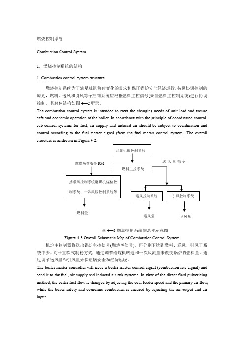
燃烧控制系统Combustion Control System1.燃烧控制系统的结构1. Combustion control system structure燃烧控制系统为了满足机组负荷变化的需求和保证锅炉安全经济运行,按照协调控制的原则,燃料、送风和引风等子控制系统应根据燃料主控信号(来自燃料主控制系统)进行协调控制。
其总体结构如图4—2所示。
The combustion control system is intended to meet the changing needs of unit load and ensure safe and economic operation of the boiler. In accordance with the principle of coordinated control, sub-control systems for fuel, air supply and induced air should be subject to coordination and control according to the fuel master signal (from the fuel master control system). The overall structure is as shown in Figure 4-2.图4—3燃烧控制系统的总体示意图Figure 4-3 Overall Schematic Map of Combustion Control System 机炉主控制器将送出锅炉主控信号(燃烧率信号),再分别下达到燃料、送风、引风子系统中去。
对于直吹式制粉方式,通过调节给煤机转速和一次风流量来改变锅炉的燃料量,通过调节送风量和引风量来保证锅安全和经济燃烧。
The boiler master controller will issue a boiler master control signal (combustion rate signal) and send it to the fuel, air supply and induced air sub-systems. In view of the direct-fired pulverizing method, the boiler fuel flow is changed by adjusting the coal feeder speed and the primary air flow, while the boiler safety and economic combustion is ensured by adjusting the air output and air input.由图4—3可见,当机组负荷变化需要改变燃料量时,由负荷控制系统中的燃料主控系统根据锅炉负荷指令产生燃煤负荷指令和风量指令,其中燃煤负荷指令送往燃料控制系统(包括磨煤机料位/给煤机转速控制、燃油控制、一次风压力控制、携带风控制和旁路风控制系统等)、送风控制系统(包括送风机压力控制、燃烧风控制系统等)和引风控制系统,使燃料、送风、引风等共同适应负荷变化,保证锅炉安全经济运行。
锅炉的计算机控制外文翻译外文文献英文文献

英文翻译Boiler computer controlBoiler computer control:The boiler micro computer control, is a new technology which the recent years developed, it was the microcomputer soft, the hardware, the automatic control, the boiler energy conservation and soon several technical in close integration with product, our country existing center, small boiler more than 300,000, the coal consumption accounted for our country raw coal output every year 1/3, at present the majority industry boiler still was at the energy consumption to be high, to waste, the environmental pollution in a big way and so on the serious production condition. Enhances the thermal efficiency, reduces the coal consumption, carries on the control with the microcomputer is has the profound significance the work. As the boiler control device, its primary mission is guaranteed the boiler the security, is stable, the economical movement, reduces operator's labor intensity. Uses the micro computer control, can carry on the process to the boiler the automatic detection, the automatic control and so on many functions. The boiler microcomputer control system, generally is composed by the below several parts, namely by the boiler main body, a measuring appliance, the microcomputer, the hand automatic cut over operation, the implementing agency and the valve, the slippery difference electrical machinery and so on partially is composed, a measuring appliance the boiler temperature, the pressure, the current capacity, the oxygen quantity, the rotational speed isometric transforms the voltage, the electric current and so on sends in the microcomputer, the hand automatic cut over operation part, manual when by the operator hand control, controls the slippery difference electrical machinery and the valve with themanipulator and so on, is automatic when sends out the control signal to the microcomputer partially to carry on the automatic operation after the execution. The microcomputer carries on the monitor to the entire boiler movement, reports to the police, the control guaranteed the boiler is normal, reliably moves, except for this for guaranteed the boiler movement these curity, when carries on the microcomputer system design, to the boiler water level, the boiler dome pressure and so on the important parameter should establish the conventional measuring appliance and the alarm device, guaranteed the water level and the dome pressure have the dual even tertiary alarm device, this is essential, in order to avoid the boiler has the significant accident.Control system:The boiler is a more complex controlled member, it not only adjustment quantity many, moreover between various types and quantities mutually relates, mutually affects, mutually restricts, boiler interior energy conversion mechanism quite complex, therefore must establish a more ideal mathematical model to the boiler quite to be difficult. Therefore, has made the boiler system simplification processing, decomposes is three relatively independent governing systems. Certainly also may subdivide other system like amount of wind control loops in certain systems, but it mainly is following three parts: (1) the chamber negative pressure (2) the boiler combustion process has three duties for the main tuning quantity special burning regulator system: To coal control, to wind control, chamber negative pressure control. The maintenance coal gas and the air proportion cause the air too much coefficient about 1.08, the combustion process efficiency, the maintenance chamber negative pressure, therefore the boiler combustion process automatic control is a complex question. As for 3×6.5t/h the boiler burning diffuses the blast furnace coal gas, the request is the blast furnace coal gas which maximum limit uses diffuses, therefore may most greatly strive according to the boiler to move, does not make the strict request to the steam pressure; The burning efficiency does not make a higher request. Such boiler combustion process automatic control simplifies as the chamber negativepressure primarily parameter decides the coal gas flow control. (3) the chamber negative pressure Pf size is directed the amount of wind, the drum amount of wind and the coal spirit (pressure)three influences. The chamber negative pressure too is small, the chamber and outside divulges the blast furnace coal gas to the outside to riching, endangers the equipment and the movement personnel's security. The negative pressure too is big, the chamber leaks the amount of wind to increase, discharges fume the loss to increase, drawing fan electricity consumes the increase. Tried to find out according to the many years man-power manual regulation that, 6.5t/hboiler Pf=100Pa carries on the design. The adjustment method is the original state first by the manual regulation air and the coal gas proportion, achieved the ideal burning condition, all opens when the drawing fan achieved chamber negative pressure 100Pa, after the investment is automatic, only adjusts the coal gas reed valve, enable under the fluctuation of pressure the blast furnace coal gas current capacity to tend to the original state coal gas current capacity, maintains in burning the blast furnace coal gas and the air proportion achieves the optimum condition.Boiler water-level control unit :The steam drum water level is affects the boiler safe operation the important parameter, the water level excessively high, can destroy the soft drink disengaging gear the normal work, is serious when can cause the steam including water to increase, increases on the pipe wall the scaling and the influence steam quality. Water level excessively low, then can destroy the water cycle, causes Water Wall bursting, is serious when can create does the pot, damages the steam drum. Therefore its value has outdone lowly all possibly creates the significant accident. It is adjusted the quantity is the steam drum water level, but adjusts the quantity is for the water current capacity, through to gives the water current capacity the adjustment, enables the steam drum interior the material to achieve the dynamical equilibrium, changes in the permission scope, because the boiler steam drum water level assumes the positive character isticto the vapor current capacity and for the fluent quantity changer But when load (vapor current capacity) sharp growth, the performance actually is "Counter response characteristic "Namely so-called " False water level " Creates this reason is because time load increase, causes the dome pressure to drop, causes the steam drum boiling temperature to drop, the water ebullition suddenly intensifies, forms the massive steam bubbles, but makes the water level to raise. The steam drum water monitor system, in the essence is maintains the boiler turnover water volume balance the system. It is by the water level took the water volume balance or not control target, through adjusts the water volume how many to achieve the turnover balance, maintains the steam drum water level in the soft drink separation contact surface biggest steam drum nearby the position line, enhances the boiler the vaporization efficiency, the guarantee production safety. Because the boiler water level system is equipped with Since the balance the ability to control the object, in the movement has the false water level phenomenon, in the practical application may use the water level single impulse, the water level steam quantity double weight and the water level, the steam quantity according to the situation, gives the water volume three impulses the control systems. Eliminates the oxygen pressure and the water-level control: Partially eliminates the oxygen to use the single impulse control plan, single return route PID adjustment.Monitoring management system management system:Above the control system generally completes the control by PLC or other hardware systems below, but must complete the function in on position computer: Real-time accurately examines the boiler the movement parameter: For comprehensively grasps the overall system the movement operating mode, the supervisory system the real-time monitor and the gathering boiler related craft parameter, the electrical parameter, as well as the equipment running status and so on. The system has the rich graph storehouse, through the configuration may the boiler equipment graph together with the related movement parameter demonstration in the picture; In addition, but also can tabulate the parameter or form and so on grouping demonstrates. The generalized analysis promptly sends out the control command: The supervisory system basis monitors the boiler performance data, according to the control strategy which establishes, sends out the control command, adjusts the boilersystem equipment the movement, thus guaranteed the boiler is highly effective, the reliable movement.(1) diagnoses the breakdown with to report to the police the management: The host controls the center to be allowed to demonstrate, the management, the transmission boiler movement each kind of alarm, thus causes boiler safe explosion-proof, the safe operation rank big enhancement. At the same time, to the records management which reports to the police may cause the owner regarding boiler movement each kind of question, weakness and so on to know from A to Z. In order to guarantee the boiler systematic security, reliably moves, the supervisory system will act according to the parameter which will monitor to carry on the breakdown diagnosis, once will break down, the supervisory system promptly on the operator screen the visual display alarm spot. Reports to the police the correlation demonstration function to cause the user definition the demonstration picture to relate with each spot, like this, when reports to the police occurs, the operator may immediately visit should report to the police the emergency procedures which detailed information and defers to recommends adopts to carry on processing. (2) historic record movement parameter: The supervisory system real-time database will maintain the boiler movement parameter the historic record, moreover supervisory system also. Is equipped with special reports to the police the event diary, with records reports to the police/the event information and operator's change The historic record data basis operator's request, the system may demonstrate is the spurt value, also may for some period of time in mean value. The historic record data may have the many kinds of display mode, for example display mode and so on curve, specific graph, report form; In addition the historic record data also may by apply take the network as the foundation many kinds of application software. (3) calculates the movement parameter: The boiler movement certain movement parameters cannot directly survey ,like the year movement load, the steam consumption, make up the water volume, the condensed water returns to the quantity, the equipment accumulation running time and so on. The supervisory system has provided the rich standard processing algorithm, according to movement parameter which obtains, Derived quantity calculates these.译文:锅炉的计算机控制锅炉的计算机控制:锅炉微计算机控制,是近年来开发的一项新技术,它是微型计算机软、硬件、自动控制、锅炉节能等几项技术紧密结合的产物,我国现有中、小型锅炉30多万台,每年耗煤量占我国原煤产量的1/3,目前大多数工业锅炉仍处于能耗高、浪费大、环境污染等严重的生产状态。
外文翻译----燃气锅炉控制系统

附录2燃气锅炉控制系统锅炉燃烧系统是使燃料燃烧所产生的热量,适应蒸汽负荷的需要,同时还要保证经济燃烧和锅炉安全运行。
首先,要维持蒸汽母管的蒸汽压力不变,采用双交叉限幅控制,使锅炉系统无论在负荷上升或下降时都能满足“负荷增加时,先增加空气量,后增加燃料量;负荷减少时,先减少燃料量,后减少空气量”,以使锅炉燃烧持续保持在无黑烟状态;其次,保持锅炉燃烧的经济性,以达到最小的热量损失和最大的燃烧效率;最后,始终维持炉膛负压在一定范围内,以使燃烧工况、锅炉房工作条件、锅炉的维护及安全运行都最有利。
在工业锅炉燃烧过程中,用常规仪表进行控制,存在滞后、间歇调节、烟气中氧含量超过给定值、低负荷和烟气温度过低等问题。
采用PLC 对锅炉进行控制时,由于它的运算速度快、精度高、准确可靠,可适应复杂的、难于处理的控制系统。
因而,可以解决以上由常规仪表控制难以解决的问题。
负荷调节是以蒸汽压力为主调参数,蒸汽流量为前馈信号,并考虑鼓风量的影响而进行的复杂PID 串级调节;氧量调节通过氧量信号、蒸汽流量及鼓风量来调节炉排电机转速,控制给煤量;炉膛压力调节以炉膛压力为主调参数,鼓风量为前馈信号进行P I 调节,控制引风机转速; 在锅炉燃烧控制中,对蒸汽压力极高进行越限报警及联锁控制:即当蒸汽压力高于报警上限时,产生上限越限声光报警,当蒸汽压力高于报警上上限时,除进行越限声光报警外,PLC 发出联锁控制信号,强制鼓风电机、引风电机及炉排电机停机,锅炉紧急停炉,以保证安全生产。
系统硬件组成根据工艺特点及锅炉的位置分布,选择IPC 和PLC 组成基于IPC- PLC 的三级DCS 监控系统,整个控制系统的组成图。
用三台西门子S7- 300 系列PLC 分别控制三台锅炉,安装在中控室。
PLC 用西门子的Step7 软件进行硬件组态, 所有的PID 控制、联锁保护、开关量控制均在PLC 上实现。
三台PLC 通过以太网与上位工控机相连, 将现场采集的数据传给上位工控机, 并接收上位工控机的各种数据和控制命令。
热电联产中英文对照外文翻译文献
中英文对照外文翻译文献(文档含英文原文和中文翻译)外文文献:The Optimal Operation Criteria for a Gas Turbine Cogeneration System Abstract: The study demonstrated the optimal operation criteria of a gas turbine cogeneration system based on the analytical solution of a linear programming model. The optimal operation criteria gave the combination of equipment to supply electricity and steam with the minimum energy cost using the energy prices and the performance of equipment. By the comparison with a detailed optimization result of an existing cogeneration plant, it was shown that the optimal operation criteria successfully provided a direction for the system operation under the condition where the electric power output of the gas turbine was less than the capacity.Keywords: Gas turbine; Cogeneration; Optimization; Inlet air cooling.1. IntroductionCogeneration, or combined heat and power production, is suitable for industrial users who require large electricity as well as heat, to reduce energy and environmental impact. To maximize cogeneration, the system has to be operated with consideration electricity and heat demands andthe performance of equipment. The optimal operation of cogeneration systems is intricate in many cases, however, due to the following reasons. Firstly, a cogeneration system is a complex of multiple devices which are connected each other by multiple energy paths such as electricity, steam, hot water and chilled water. Secondly, the performance characteristics of equipment will be changed by external factors such as weather conditions.For example, the output and the efficiency of gas turbines depend on the inlet air temperature. Lastly,the optimal solution of operation of cogeneration systems will vary with the ratio of heat demand to electricity demand and prices of gas, oil and electricity.Because of these complexities of cogeneration systems, a number of researchers have optimal solutions of cogeneration systems using mathematical programming or other optimization techniques. Optimization work focusing on gas turbine cogeneration systems are as follows. Yokoyama et al. [1] presented optimal sizing and operational planning of a gas turbine cogeneration system using a combination of non-linear programming and mixed-integer linear programming methods. They showed the minimum annual total cost based on the optimization strategies. A similar technique was used by Beihong andWeiding [2] for optimizing the size of cogeneration plant. A numerical example of a gas turbine cogeneration system in a hospital was given and the minimization of annual total cost was illustrated. Kong et al. [3] analyzed a combined cooling, heating and power plant that consisted of a gas turbine, an absorption chiller and a heat recovery boiler. The energy cost of the system was minimized by a linear programming model and it was revealed that the optimal operational strategies depended on the load conditions as well as on the cost ratio of electricity to gas. Manolas et al. [4] applied a genetic algorithm (GA) for the optimization of an industrial cogeneration system, and examined the parameter setting of the GA on the optimization results. They concluded that the GA was successful and robust in finding the optimal operation of a cogeneration system.As well as the system optimization, the performance improvement of equipment brings energy cost reduction benefits. It is known that the electric power output and the efficiency of gas turbines decrease at high ambient temperatures. Some technical reports [5, 6] show that the electric power output of a gas turbine linearly decreases with the rise of the ambient temperature, and it varies about 5 % to 10 % with a temperature change of 10 ◦C. Therefore, cooling of the turbine inlet air enhances electric output and efficiency. Some studies have examined theperformance of the gas turbine with inlet air cooling as well as the effect of various cooling methods [7, 8, 9].The cooling can be provided without additional fuel consumption by evaporative coolers or by waste heat driven absorption chillers. The optimal operation of the system will be more complex, however, especially in the case of waste heat driven absorption chillers because the usage of the waste heat from the gas turbine has to be optimized by taking into consideration the performance of not only the gas turbine and the absorption chiller but also steam turbines, boilers and so on. The heat and electricity demands as well as the prices of electricity and fuels also influence the optimal operation.The purpose of our study is to provide criteria for optimal operation of gas turbine cogeneration systems including turbine inlet air cooling. The criteria give the minimum energy cost of the cogeneration system. The method is based on linear programming and theKuhn-Tucker conditions to examine the optimal solution, which can be applied to a wide range of cogeneration systems.2. The Criteria for the Optimal Operation of Gas Turbine Cogeneration SystemsThe criteria for the optimal operation of gas turbine cogeneration systems were examined from the Kuhn-Tucker conditions of a linear programming model [10]. A simplified gas turbine cogeneration system was modeled and the region where the optimal solution existed was illustrated on a plane of the Lagrange multipliers.2.1. The Gas Turbine Cogeneration System ModelThe gas turbine cogeneration system was expressed as a mathematical programming model. The system consisted of a gas turbine including an inlet air cooler and a heat recovery steam generator (HRSG), a steam turbine, an absorption chiller, a boiler and the electricity grid. Figure 1 shows the energy flow of the system. Electricity, process steam, and cooling for process or for air-conditioning are typical demands in industry, and they can be provided by multiple suppliers. In the analysis, cooling demands other than for inlet air cooling were not taken into account, and therefore, the absorption chiller would work only to provide inlet air cooling of the gas turbine. The electricity was treated as the electric power in kilowatts, and the steam and the chilled water were treated as the heat flow rates in kilowatts so that the energy balance can be expressed in the same units.Figure 1. The energy flow of the simplified gas turbine cogeneration system with the turbineinlet air cooling.The supplied electric power and heat flow rate of the steam should be greater than or equal to the demands, which can be expressed by Eqs. (1-2).(1)(2)where, xe and xs represent the electric power demand and the heat flow rate of the steam demand. The electric power supply from the grid, the gas turbine and the steam turbine are denoted by xG, xGT and xST, respectively. xB denotes the heat flow rate of steam from the boiler, and xAC denotes the heat flow rate of chilled water from the absorption chiller. The ratio of the heat flow rate of steam from the HRSG to the electric power from the gas turbine is denominated the steam to electricity ratio, and denoted by ρGT. Then, ρGTxGT represents the heat flow rate o f steam from the gas turbine cogeneration. The steam consumption ratios of the steam turbine and the absorption chiller are given as ωST and ωAC, respectively. The former is equivalent to the inverse of the efficiency based on the steam input, and the latter is equivalent to the inverse of the coefficient of performance.The inlet air cooling of the gas turbine enhances the maximum output from the gas turbine. By introducing the capacity of the gas turbine, XGT, the effect of the inlet air cooling was expressed by Eq. (3).(3).It was assumed that the increment of the gas turbine capacity was proportional to the heatflow rate of chilled water supplied to the gas turbine. The proportional constant is denoted byαGT.In addition to the enhancement of the gas turbine capacity, the inlet air cooling improves the electric efficiency of the gas turbine. Provided that the improvement is proportional to the heat flow rate of chilled water to the gas turbine, the fuel consumption of the gas turbine can be expressed as ωGTxGT¡βGTxAC, whereωGT is the fuel consumption ratio without the inlet air cooling and βGT is the improvement factor of the fuel consumption by the inlet air cooling. As the objective of the optimization is the minimization of the energy cost during a certain time period, Δt, the energy cost should be expressed as a function of xG, xGT, xST, xB and xAC. By defining the unit energy prices of the electricity, gas and oil as Pe, Pg and Po, respectively, the energy cost, C, can be given as:(4)where, ωB is the fuel consumpti on ratio of the boiler, which is equivalent to the inverse of the thermal efficiency.All the parameters that represent the characteristics of equipment, such as ωGT, ωST, ωAC, ωB, ρGT, αGT and βGT, were assumed to be constant so that the system could be m odeled by the linear programming. Therefore, the part load characteristics of equipment were linearly approximated.2.2. The Mathematical Formulation and the Optimal Solution From Eqs. (1–4), the optimization problem is formed as follows:(5)(6)(7)(8)where, x = (xG, xGT, xST, xB, xAC). Using the Lagrange multipliers, λ = (λ1, λ2, λ3), theobjectivefunction can be expressed by the Lagrangian, L(x,λ).(9)According to the Kuhn-Tucker conditions, x and λ satisfy the following conditions at the optimal solution.(10)(11)(12)(13)The following inequalities are derived from Eq. (10).(14)(15)(16)(17)(18)Equation (11) means that xi > 0 if the derived expression concerning the supplier i satisfies the equali ty, otherwise, xi = 0. For example, xG has a positive value if λ1 equals PeΔt. If λ1 is less than PeΔt, then xG equals zero.With regard to the constraint g3(x), it is possible to classify the gas turbine operation into two conditions.The first one is the case where the electric power from the gas turbine is less than the capacity,which means xG < XGT + αGTxAC. The second one is the case where the electric power from the gas turbine is at the maximum, which means xGT = XGT + αGTxAC. We denominate the former and the latter conditions the operational conditions I and II, respectively. Due to Eq. (12) of the Kuhn-Tucker condition, λ3 = 0 on the operational condition I, and λ3 > 0 on the operational condition II.2.3. The Optimal Solution where the Electric Power from the Gas Turbine is less than theCapacityOn the operational condition I where xG < XGT + αGTxAC, Eqs. (14–18) can be drawn on the λ1-λ2 plane because λ3 equals zero. The region surrounded by the inequalities gives the feasible solutions, and the output of the supplier i has a positive value, i.e. xi > 0, when the solution exists on the line which represents the supplier i.Figure 2 illustrates eight cases of the feasible solution region appeared on the λ1-λ2 plane. The possible optimal solutions ar e marked as the operation modes “a” to “g”. The mode a appears in the case A, where the grid electricity and the boiler are chosen at the optimal operation. In the mode b,the boiler and the steam turbine satisfy the electric power demand and the heat flow rate of the steam demand. After the case C, the electric power from the gas turbine is positive at the optimal operation.In the case C, the optimal operation is the gas turbine only (mode c), the combination of the gas turbine and the boiler (mode d) or the combination of the gas turbine and the grid electricity (mode e). In this case, the optimal operation will be chosen by the ratio of the heat flow rate of the steam demand to the electric power demand, which will be discussed later. When the line which represents the boiler does not cross the gas turbine line in the first quadrant, which is the case C’, only the modes c and e appear as the possible optimal solutions. The modes f and g appear in the cases D and E, respectively. The suppliersThe cases A through E will occur depending on the performance parameters of the suppliers and the unit energy prices. The conditions of each case can be obtained from the graphical analysis. For example, the case A occurs if λ1 at the intersection of G and B is smaller than that at the intersection of GT and B, and is smaller than that at the intersection of ST and B. In addition, the line B has to be located above the line AC so that the feasible solution region exists. Then, the following conditions can be derived.(19)(20)(21)Equation (19) means that the gas cost to produce a certain quantity of electricity and steam with the gas turbine is higher than the total of the electricity and oil costs to purchase the same quantity of electricity from the grid and to produce the same quantity of steam with the boiler.Equation (20) means that the electricity cost to purchase a certain quantity of electricity is cheaper than the oil cost to produce the same quantity of electricity using the boiler and the steam turbine. Equation (21) indicates that the reduction of the gas cost by a certain quantity of the inlet air cooling should be smaller than the oil cost to provide the same quantity of cooling using the boiler and the absorption chiller. Otherwise, the optimal solution does not exist because the reduction of the gas cost is unlimited by the inlet air cooling using the absorption chiller driven by the boiler.Figure 2. The possible cases of the optimal solution on the operational condition ISimilar ly, the following conditions can be derived for the other cases. The condition given as Eq. (21) has to be applied to all the cases below.Case B:(22)(23)Equation (22) compares the production cost of the electricity and the steam between the gas and the oil. The gas cost to produce a certain quantity of electricity and steam by the gas turbine is higher than the oil cost to produce the same quantity of electricity and steam by thecombination of the boiler and the steam turbine. Equation (23) is the opposite of Eq. (20), which means that the oil cost to produce a certain quantity of electricity by the boiler and the steam turbine is cheaper than the purchase price of electricity.Case C:(24)(25)(26)(27)Equation (24) is the opposite case of Eq. (19). Equation (25) compares the boiler and the gas turbine regarding the steam production, which is related to the mode d. In the case C, the oil cos t for the boiler is cheaper than the gas cost for the gas turbine to produce a certain quantity of steam. If the gas cost is cheaper, mode d is not a candidate for the optimal sol ution, as illustrated in the case C’. Equations (26) and (27) evaluate the effectiveness of the steam turbine and the inlet air cooling by the absorption chiller,resp ectively. The grid electricity is superior to the steam turbine and to the inlet air cooling in this case.Case D:In addition to Eq. (25),(28)(29)(30)Similarly to the case C’, the case D’ occurs if the inequality sign of Eq. (25) is reversed. Equation (28) is the opposite case of Eq. (22), which is the comparison of the electricity production between gas and oil. Equation (29) is the opposite case of Eq. (26), which is the comparison of the steam turbine and grid electricity. The gas cost to produce a certain quantity of electricity by the combination of the gas turbine and the steam turbine is cheaper than the purchase cost of the same quantity of electricity from the grid. Equation (30) gives the condition where the steam turbine is more advantageous than the inlet air cooling by the absorption chiller. The left hand side of Eq. (30) represents an additional steam required for a certain quantity of electricity production by the inlet air cooling. Therefore, Eq. (30) insists that the steam required for a certain quantity of electricity production by the steam turbine is smaller than that requiredfor the same quantity of electricity production by the inlet air cooling in this case, and it is independent of energy prices.Case E:In addition to Eq.(25),(31)(32)The case E’ occurs if Eq. (25) is reversed. Equations (31) and (32) are the opposite cases of Eqs. (27)and (30), which give the conditions where the inlet air cooling is more advantageous compared with the alternative technologies. In this case, Eq. (28) is always satisfied because of Eqs. (21) and (32).The conditions discussed above can be arranged using the relative electricity price, Pe/Pg and the relative oil price, Po/Pg. The optimal cases to be chosen are graphically shown in Figure 3 on the Po/Pg-Pe/Pg plane. When Eq. (30) is valid, Figure 3 (a) should be applied. The inlet air cooling is not an optimal option in any case. When Eq. (32) is valid, the cases E and E’ appear on the plane and the steam turbine is never chosen, as depicted in Figure 3 (b). It is noteworthy that if the inlet air cooling cannot improve the gas turbine efficiency, i.e. βGT = 0, the inlet air cooling is never the optimal solution.As the cases C, D and E include three operation modes, another criterion for the selection of the optimal operation mode is necessary in those cases. The additional criterion is related with the steam to electricity ratio, and can be derived from the consideration below.In the c ases C, D and E, λ1 and λ2 have positive values. Therefore, two of the constraints given as Eqs. (6) and (7) take the equality conditions due to the Kuhn-Tucker condition Eq. (12). Then, the two equations can be solved simultaneously for two variables which have positive values at each mode.For the mode d, the simultaneous equations can be solved under xGT, xB > 0 and xG, xST, xAC = 0.Then, one can obtain xGT = xe and xB = xs ¡ ρGTxe. Because xB has a positive value, the following condition has to be satisfied for the mode d to be selected.(33)At the mode e, one can obtain xG = xe ¡ xs/ρGT and xGT = xs/ρGT, and the following condition can be drawn out of the former expression because xG is greater than zero at this mode.(34)Similar considerations can be applied to the cases D and E. Consequently, Eq. (33) is the condition for the mode d to be selected, while Eq. (34) is the condition for the modes e, f or g to be selected. Furthermore, it is obvious that the mode c has to be chosen if the steam to electricity ratio of the gas turbine is equal to the ratio of the heat flow rate of the steam demand to the electric power demand, i.e. ρGT = xs/xe.Equations (33) and (34) mean that when the steam to electricity ratio of the gas turbine is smaller than the ratio of the heat flow rate of the steam demand to the electric power demand, the gas turbine should be operated to meet the electric power demand. Then, the boiler should balance the heat flow rate of the steam supply with the demand. On the other hand, if the steam to electricity ratio of the gas turbine is larger than the ratio of the heat flow rate of the steam demand to the electric power demand,the gas turbine has to be operated to meet the heat flow rate of the steam demand. Then, the insufficient electric power supply from the gas turbine has to be compensated by either the grid (mode e), the steam turbine (mode f), or the inlet air cooling (mode g). There is no need of any auxiliary equipment to supply additional electric power or steam if the steam to electricity ratio of the gas turbine matches the demands.Figure 3. The optimal operation cases expressed on the relative oil price-relative electricity price plane (the operational condition I).2.4. The Optimal Solution where the Electric Power from the Gas Turbine is at the MaximumIn the operational condition II, the third constraint, Eq. (8), takes the equality condition and λ3 would have a positive value. Then, Eqs. (11) and (18) yields:(35)It is reasonable to assume that ρGT ¡ !AC ®GT > 0 and ωGT ¡ ¯GT ®GT > 0 in the case ofgas turbine cogeneration systems because of relatively low electric efficiency (¼ 25 %) and a high heat to electricity ratio (ρGT > 1.4). Then, the optimal solution cases c an be defined by a similar consideration to the operational condition I, and the newly appeared cases are illustrated in Figure 4. The cases F and G can occur in the operational condition II in addition to the cases A and B of the operational condition I. Similarly to the cases C’ and D’ of the operational condition I, the cases F’ and G’ can be defined where the mode h is excluded from the cases F and G, respectively.Figure 4. The optimal solution cases on the operational condition II.In the operational condition II, the conditions of the cases A and B are slightly different from those in the operational condition I, as given below.Case A:(36)(37)Case B:(38)(39)The conditions for the cases F and G are obtained as follows.Case F:(40)(41)(42)Case G:In addition to Eq. (41),(43)(44)The case s F’ and G’ occur whenthe inequality sign of Eq. (41) is reversed. Equations (36), (38),(40), (41), (42), (43) and (44) correspond to Eqs. (19), (22), (24), (25), (26), (28) and (29), respectively.In these equations, ωGT ¡ ¯GT®GTis substituted for ωGT, an d ρGT ¡ !AC®GTis substituted for ρGT.The optimal cases of the operational condition II are illustrated on the Po/Pg-Pe/Pg plane as shown in Figure 5. Unlike the operational condition I, there is no lower limit of the relative oil price for the optimal solution to exist. The line separating the cases F and G is determined by the multiple parameters.Basically, a larger ρGT or a smaller ωST lowers the line, which causes a higher possibility for the case G to be selected.Figure 5. The optimal operation cases expressed on the relative oil price-relative electricity price plane (the operational condition II).To find the optimal mode out of three operation modes included in the cases F or G, another strategy is necessary. The additional conditions can be found by a similar examination on the variables to that done for the cases C, D and E. In the operational condition II, three variables can be analytically solved by the constraints given as Eqs. (6), (7) and (8) taking equality conditions.In the mode g, only two variables, ωGT andωAC are positive and the other variables are equal to zero.Therefore, the analytical solutions of those in the operational condition II can be obtained from equations derived from Eqs. (6) and (7) as xGT = xe and xAC = (ρGTxe ¡xs)/ωA C. Then the third constraint gives the equality condition concerning xs/xe and XGT/xe as follows:(45)where, XGT/xe represents the ratio of the gas turbine capacity to the electricity demand, and XGT/xe ·1.For mode h, the condition where this mode should be selected is derived from the analytical solution of xB with xB > 0 as follows:(46)For the mode i, xG > 0 and xAC > 0 give the following two conditions.(47)(48)For the mode j, xST > 0 and xAC > 0 give the following conditions.(49)(50)The conditions given as Eqs. (45–50) are graphically shown in Figure 6. In the cases F and G,the operational condition II cannot be applied to the region of xsxe< ρGTXGT xeand xsxe<(ωST+ρGT)XGTxe¡ωST,respectively, because xAC becomes negative in this region. The optimal operation should be found under the operational condition I in this region.3. Comparison of the Optimal Operation Criteria with a Detailed Optimization ResultTo examine the applicability of the method explained in the previous section to a practical cogeneration system, the combination of the suppliers selected by the optimal operation criteria was compared with the results of a detailed optimization of an existing plant.3.1. An Example of an Existing Energy Center of a FactoryAn energy center of an existing factory is depicted in Figure 7. The factory is located in Aichi Prefecture, Japan, and produces car-related parts. The energy center produces electricity by a combined cycle of a gas turbine and a steam turbine. The gas turbine can be fueled with either gas or kerosene, and it is equipped with an inlet air cooler. The electric power distribution system of the factory is also linked to the electricity grid so that the electricity can be purchased in case the electric power supply from the energy center is insufficient.The steam is produced from the gas turbine and boilers. The high, medium or low pressure steam is consumed in the manufacturing process as well as for the driving force of the steam turbine and absorption chillers. The absorption chillers supply chilled water for the process, air conditioning and the inlet air cooling. One of the absorption chiller can utilize hot water recovered from the low temperature waste gas of the gas turbine to enhance the heat recovery efficiency of the system.Figure 6. The selection of the optimal operation mode in the cases of F and G.3.2. The Performance Characteristics of the EquipmentThe part load characteristics of the equipment were linearly approximated so that the system could be modeled by the linear programming. The approximation lines were derived from the characteristics of the existing machines used in the energy center.The electricity and the steam generation characteristics of the gas turbine and the HRSG are shown in Figure 8, for example. The electric capacity of the gas turbine increases with lower inlet air temperatures. The quantity of generated steam is also augmented with lower inlet air temperatures.In practice, it is known that the inlet air cooling is beneficial when the purchase of the grid electricity will exceed the power contract without the augmentation of the gas turbine capacity. Furthermore, the inlet air cooling is effective when the outdoor air temperature is higher than 11 ◦C. A part of the operation of the actual gas turbine system is based on the above judgement of the operator, which is also included in the detailed optimization model.3.3. The Detailed Optimization of the Energy CenterThe optimization of the system shown in Figure 7 was performed by a software tool developed for this system. The optimization method used in the tool is the linear programming method combined with the listed start-stop patterns of equipment and with the judgement whether the inlet air cooling is on oroff. The methodology used in the tool is fully described in the reference [11].Figure 7. An energy center of a factory.Figure 8. The performance characteristics of the gas turbine and the HRSG.The Detailed Optimization MethodThe energy flow in the energy center was modeled by the linear programming. The outputs of equipment were the variables to be optimized, whose values could be varied within the lower and upper limits. To make the optimization model realistic, it is necessary to take the start-stop patterns of the equipment into account. The start-stop patterns were generated according to thepossible operation conditions of the actual energy center, and 20 patterns were chosen for the enumeration. The optimal solution was searched by the combination of the enumeration of the start-stop patterns and the linear programming method. The list of the start-stop patterns of the gas turbine and the steam turbine is given in Figure 9.The demands given in the detailed optimization are shown in Figure 10 as the ratios of the heat flow rate of the steam demand to the electric power demand on a summer day with a large electric power demand and on a winter day with a small steam demand. On the summer day, the ratio of the heat flow rate of the steam demand to the electric power demand is at a low level throughout a day. While, it is high on the winter day, and during the hours 2 to 6, the ratio exceeds 1.4 that is the steam to electricity ratio of the gas turbine.Figure 9. The start-stop patterns of the gas turbine and the steam turbine.The Plant Operation Obtained by the Detailed OptimizationThe accumulated graphs shown in Figures 11 through 14 illustrate the electric power supply and the heat flow rate of the steam supply from equipment on the summer and winter days. On the summer day, the gas turbine and the steam turbine worked at the maximum load and the electric power demand was met by the purchase from the grid for most of the day except the hours 2 to 6, at which the electric power demand was small. The inlet air cooling of the gas turbine was used only at the hours 10 and 14, at which the peak of the electric power demand existed. The steam was mainly supplied by the gas turbine, and the boiler was used only if the total heat flow rate of the steam demands by the process, the steam turbine, and the absorption。
排气控制系统外文文献翻译、中英文翻译、外文翻译
英文资料翻译Emission Control SystemsThe purpose of the emission system is just that it controls the emission and exhaust from a vehicle. The idea is to turn the harmful gases a car manufactures into harmless ones that don't ruin the environment, or persons. Some of problem gases are:1.hydrocarbons(unburned).2.Carbon monoxide.3.Carbon dioxide4.Nitrogen oxide.5.Sulfur dioxide.6.Phosphorus.7.Lead and other metal.There are five popular systems used to reduce emissions: the crankcase ventilation system, the evaporative emissions control system, the exhaust gas recirculation system and the catalytic converter system. In additional to these emissions system, some vehicles incorporate an electronically controlled fuel system, which further reduces emissions.Note: Not all vehicles are equipped with these emission systems.Crankcase ventilation systemSince the early 1960s, all cars have been equipped with crankcase ventilation system.When the engine is running, a small portion of the gases which are formed in the combustion chamber leak pas the piston rings and enter the crankcase. Since these gases are under pressure, they tend to escape from the crankcase and enter the atmosphere. if these gases are allowed to remain in the crankcase for any length of time, they contaminate the engine oil and cause sludge to build up in the crankcase. If the gases are allowed to escape to the atmosphere, they pollute the air with unburned hydrocarbons. The job of the crankcase ventilationsystem is to recycle thee gases back into the engine combustion chamber where they are re-burned.The crankcase gases are recycled as the engine is running by drawing clean filtered air through the air filter and into the crankcase. As they are passes through the crankcase, it picks up the combustion gases and carries them out of the crankcase, through the oil separator, through the PCV valve or orifice, and into the induction system. as they enter the intake manifold, they are drawn into the combustion chamber where they are re-burned.The most critical component in the system is the PCV valve that controls the amount of gases that are recycled. At low engine speed increases, the valve opens to admit greater quantities of air to the intake manifold. Some systems do not use a PCV valve. They simply use a restrictor or orifice in the ventilation hose to meter the crankcase gases.If the PCV valve becomes blocked or plugged, the gases can not be vented from the crankcase. Since they are under pressure, they ill find their own way out of the crankcase. This alternate route is usually a weak oil seal or gasket in the engine. As the gas escapes by the gasket, it usually creates an oil leak. Besides causing oil leaks, a clogged PCV valve also allows these gases to remain in the crankcase for an extended period, promoting the formation of sludge in the engine.Evaporative emission control systemThe evaporative emission control system is designed to prevent fuel tank and carburettor bowl vapours from being emitted into the atmosphere. Fuel vapours are absorbed and stored by a fuel vapour charcoal canister. The canister stores them until certain engine conditions are met and the vapours can be purged and burned by the engine.The charcoal canister purge cycle is controlled different ways: either by a thermostatic vacuum switch, a solenoid or by a timed vacuum source. The thermostatic switch is installed in the coolant passage and prevents canister purge when the engine is below a certain temperature. The solenoid is usually controlled by a computer and is used on feedback fuel systems. The computerdetermines when canister purge is appropriate. Depending on the system, this can be engine operating temperature, engine speed, evaporative system pressure or any combination of these. The timed vacuum source uses a manifold vacuum controlled diaphragm o control canister purge. When the engine is running, full manifold vacuum is applied to the top tube of the purge valve which lifts the valve diaphragm and opens the valve.A vent located in the fuel tank, allows fuel vapours to flow to the charcoal canister. a tank pressure control valve, used on some high altitude applications, prevents canister purge when the engine is not running. The fuel tank cap does not normally vent to the atmosphere, but is designed to provide both vacuum and pressure relief.Air injection systemIntroducing a controlled amount of air into the exhaust system promotes further oxidation of the gases. This in turn reduces the amount of carbon monoxide and water, the harmless by-products of combustion. Some system use an air pump, while other use negative exhaust pulses to draw air.The air pump, usually driven by a belt, simply pumps air under a pressure of only a few pounds into each exhaust port. Between the nozzles and the pump is a check valve to keep the hot exhaust gases from flowing back into the pump and hoses thereby destroying them. Most pumps also utilize a gulp valve or a diverter valve. Early system used a gulp valve while later systems use diverter valves. They both operate on the same principle. During deceleration, as the throttle is closed, the explosion in the exhaust system could occur that could blow the muffler apart. During deceleration, the air is either diverted into the atmosphere or into the intake system.On pulse air system, clean air is drawn through a silencer, the check valve and then into the exhaust ports. The negative exhaust pulses opens the reed valve in the check valve assembly, allowing air to flow into the exhaust port.Some feedback-controlled vehicles utilize an oxidizing catalytic converter. Under certain operating conditions, the air is diverted into the catalytic converter to help oxidize the exhaust gases.Exhaust gas re-circulation systemThe EGR system's purpose is to control oxides of nitrogen which are formed during the combustion process. NOx emissions at low combustion temperatures are not severe, but when the combustion temperatures go over 2,500F, the production of NOx in the combustion chambers shoots way up. The end products of combustion are relatively inert gases derived from the exhaust gases. these are redirected ,(under certain conditions) through the EGR valve and back into the combustion chamber. These inert gases displace a certain amount of oxygen in the chamber. Since not as much chamber. These inert gases displace a certain amount of oxygen in the chamber. Since not as much oxygen is present, the explosion is not as hot. This helps lower peak combustion temperatures.The EGR valve can either be actuated by a vacuum diaphragm, a solenoid or stepper motor. On feedback controlled vehicles, the EGR system is controlled by the computer.Catalytic converterThe catalytic converter is a muffler-like container built into the exhaust system to aid in the reduction of exhaust emissions. The catalyst element is coated with a noble metal such as platinum, palladium, rhodium or a combination of hem, when the exhaust gases come into harmless substances such as water and carbon dioxide, oxidizing catalysts into H2O and CO2.While catalytic converters are built in a variety of shapes and sizes, they all fall into two general types, the pellet, or bead type and the monolithic type. Construction may differ slightly, but the object is the same -to present the largest possible surface area to passing exhaust gases. Older vehicles use bead type converters. The exhaust gas must pass through a bed of these pellets. This type of converter is rather restrictive. The cross-section of a monolithic type converter resembles a honeycomb. The exhaust gases are exposed to a greater amount of surface area in these converters; as a result they are more efficient. They also tend to be less restrictive.Dual exhaust systemThe advantage of a dual exhaust system is that the engine exhausts morefreely, thereby lowering the backpressure, which is inherent in an exhaust .with a dual exhaust system, a sizable increase in engine horsepower can be obtained because the breathing capacity of the engine is improved, leaving less exhaust gases in the engine at the end of each exhaust stroke. This in turn, leaves more room for an extra intake of the air-fuel mixture.Hyperboloid gearOn the passenger vehicle main gear box uses the hyperbolic curve gear generally. This is because the hyperbolic curve gear and the spiral bevel gear compare, former revolution noise few, work steadier, turns the tooth intensity high, moreover also has the drive gear spool thread to be possible the relative driven gear disalignment characteristic, this point to be extremely important regarding the automobile technical performance, engineer may in not change the engine the position size to be possible to change the driving axle directly the ground clearance, also is changes the entire vehicle the ground clearance.some automobiles main gear box hyperbolic curve gear off-sets amounts to more than 30 millimeters, in the maintenance certain ground clearance situation, may reduce the drive gear and the drive shaft position, causes the automobile body center of gravity to reduce, is advantageous in enhances the automobile high speed travel the stability. Two gears spool threads intersection driving pulley displaces to underSome automobiles produce the passenger vehicle and movement on the identical frame, its chassis parameter transformation also has used hyperbolic curve gear this characteristic. Because has these merits, at present the automobile driving axle already tended to uses the hyperbolic curve gear, in fact recent years imported the automobile basically was uses the hyperbolic curve gear, the domestically produced automobile also has many vehicle types to use the hyperbolic curve gear, and already more and more were many in center, on the heavy freight vehicle obtains the use.When the hyperbolic curve gear works, between the tooth face can have in a big way skids relatively, also the tooth face pressure is very big, the tooth face lubricant film is easily destroyed. In order to reduce the friction, enhances theefficiency, must have to use includes guards against the abrasion chemical additive the special-purpose hyperbolic curve gear oil, cannot use other gear oil to replace, otherwise will cause the tooth face rapid attrition and the abrasion, seriously will affect the automobile the running status.Further developmentManufacturers around the world are seeking significant improvements in conventional automotive technologies, and Chinese manufacturers risk falling behind if they fail to sustain comparable research efforts on conventional power train systems. The Chinese automotive industry also should strengthen its efforts to develop improved diesel and spark ignition technology in cooperation with its joint venture partners. Researchers should focus on .among other things, advanced gasoline and diesel engine technologies, an ultra-low-emission gasoline engine system, diesel particulate filters, de-NO catalysts, selective catalytic reduction (SCR), and improved in-engine combustion management. Industry must develop the capability to model the vehicle power train system in order to optimize its overall performance, including fuel economy, and vehicle drivability. The automobile's further development will be determined by already existing and steadily increasing requirements, by additional further requirements and by the technical possibilities for meeting these requirements. The following focal point for development and research efforts can be discerned. Further improvement of the automobile through product innovation is in all classic functions, performance, fuel economy, environmental impact, safety, comfort, and reliability.中文翻译排气控制系统排放控制系统的目的只是为了控制车辆废气的排放。
- 1、下载文档前请自行甄别文档内容的完整性,平台不提供额外的编辑、内容补充、找答案等附加服务。
- 2、"仅部分预览"的文档,不可在线预览部分如存在完整性等问题,可反馈申请退款(可完整预览的文档不适用该条件!)。
- 3、如文档侵犯您的权益,请联系客服反馈,我们会尽快为您处理(人工客服工作时间:9:00-18:30)。
热风炉控制系统中英文对照外文翻译文献(文档含英文原文和中文翻译)译文:基于西门子pcs7的热风炉控制系统的设计本文介绍的方法利用西门子过程控制系统pcs7v6.0控制加热炉。
描述了两者的配置控制系统软件和硬件,功能通过该系统,随着困难解决方案。
加热炉控制系统的配置双cpu冗余。
采用工业以太网,欧洲流行的profibusdp现场总线和分布式i/o减反射膜结构。
它采用et200mi/o站的冗余。
带profibus-dp通信接口和节点具有双控制器的通信协议(cpu)。
一、了解在生产过程中的热轧带钢,要求对来料板坯温度比较高;一般来说,应当是1350℃左右。
的加热炉的加热程序的设备,如能满足连续可靠的要求生产只有在控新制的温度和输出量存有较好的协同。
加热炉使用可移动的STM梁移动热板坯的出口两端的输出时,炉两端;钢板坯就是移动的,它将被冷却的燃烧室喷气炉气联手焦炭炉。
当板坯浸出炉体的末端,它首先可以被冷却至850℃左右在预演段,然后约1300℃在冷却段;最后将步入热煮沸部分并使板坯冷却光滑翻转。
上述掌控过程通常通过不断的pid(比例,分数和差分)。
s分别对各掌控横截面的顶部或侧壁分别搜集实际温度在两节该炉和再取样值将被发送到plc(可编程逻辑控制器)同时实现已连续比例,分数和微分(pid掌控)通过测量值之间的差异空气和煤气流量设定值;然后开度每段的喷枪将调整掌控气体的流量,温度控制,然而,因为它不是关于气体的冷却确切,如果这使用的方法就是,热利用效率介质的极低、能耗非常小。
在这里,一种改良的双交叉振幅管制全自动冷却掌控展开了了解和其基本原理就是展开掌控冷却的上部和下部各节在正常工作时间;例如存有必要,温度将上部调整信号可以被视作套双交叉限幅掌控和在下部前温度检测值可以用作炉状态监测。
这一原则主从掌控模式可以更好地协同在上冷却和供热均衡段和下部的冷却上、下段光滑;同时,它指出天然气的冷却,起著了较好的促进作用节能环保。
在这个项目中,pcs7v6.0由西门子将用作同时实现上述掌控功能。
二、简要介绍了pcs7系统pcs7过程控制系统就是一种一流的定位系列可编程逻辑控制器和teleperm通过西门子融合最系列机器人系统一流的计算机软件和硬件技术,使用可以更改的操作方式东站,弱关系过程控制站与大容量和缓存分布式i/o总线的过程控制系统现场总线技术。
pcs7已被应用领域在越来越多的行业控制区作为一种面向过程的软件开发平台。
它提出了一种完全集成的自动化解决方案,可以提供所有种类的一个统一的自动化应用技术环境。
以下项目包括它:统一的数据管理,通信,配置和编程软件。
基于环境以上,各种技术可以集成在一个在相同的全球数据库系统整体界面与用户。
工程师或技术人员可以配置和在同一平台上的各种应用程序。
复杂的工程是通过使用一个简单的组态平台。
pcs7使plc纳入dcs系统更容易,体现真正的特征的计算机自动控制。
三、详细了解热风炉控制系统在复杂的工业过程系统,我们总是遇到这样的问题:多个约束条件的多变量系统:强耦合的非线性系统:大;时间延迟;多目标控制;等等。
自定义控件技术无法化解上述问题。
但一流控制技术可以较好的化解上述问题。
怎么用在工业过程中应用领域一流控制技术产生的实用性就是一个迫切需要化解的问题工业自动化研究领域。
根据计算机技术的B90,硬件技术,网络技术,一流控制技术的产业化技术就是可以同时实现的。
本文明确提出了有价值的难同时实现可信的掌控方式同时实现步进式加热炉自动控制系统,对的基础上,包含过程控制理论,dcs和plc技术,通信,现场总线,在步进式加热的特点炉,采用电气、仪表控制设备与技术实用、可靠和指标先进。
我们可以实现仪表控制系统利用dcs和plc电气控制系统。
控制加热炉系统分为加热炉区plc控制系统,plc控制系统和加热辊炉dcs控制系统。
仪表控制器电气连接的操作员站服务器ieee以太网,采用dcs和plc技术,网络和现场总线技术相结合的过程控制系统和过程计算机,智能仪器,实现仪器的驱动系统在一个系统的电气控制。
四、热风炉控制系统的共同组成1.控制系统配置在本文中,基于步进式加热炉掌控过程中,控制系统就是一个繁杂的热传导和字符的过程中,存有许多特点例如阻碍,弱耦合,小氢铵落后等我们探讨的基础上的专用掌控装置的设计步进式加热炉在细节包含的特点,有关的软件和硬件信息同时实现的掌控。
pid掌控就是综合掌控规律仪表控制系统,因为它的明朗,熟识在技术员和操作工,效果不好,广为的应用领域计算机数据掌控设备,特别就是繁杂的控制系统,实践证明它适应环境各种工业过程控制。
加热炉的关键设备:装载机机,卸货机,奔跑系统,系列切换辊,冷却和追踪板控制系统。
的冷凝式加热炉的控制系统使用双cpu缓存,缓存环路工业以太网,profibusdp总线和分布式i/o减反射膜结构,表明的详尽配置图1。
利用该系统,可以展开传输测量和平均值函数,追踪检测,读取和装载板,我们可以冷却和彼此间互换数据去掌控过程在所有产品线的轨道板和管理过程。
加热炉的生产工艺例如低目标产量,低消耗和污染,自动操作方式模式的同时实现。
2.硬件配置例如图1右图,在整个dcs控制系统加热炉存有两个明显的特点:的第一个就是基础自动化级使用缓存环路结构,从而提升可靠性和系统的稳定性;第二,信息层使用标准的以太网结构并使整个系统的大容量数据通信能力和便利的可扩展性。
针对上述特点以下模式通过硬件的挑选:(1)选择过程控制器中cpu414-h由西门子s7-400系列的核心的加热炉控制系统共同构成了冗余系统的控制站与分布i/oet200m;(2)监控系统使用研华工业掌控计算机和菲利普22“纯平彩色显示器工程师东站和操作员东站。
操作方式该系统的东站在形式的在线工作协同和他们就是全透明、全系列纠错,同时实现彼此的更改。
这种模式使本系统有助于可信操作方式,数据分布合理,操作方式便捷速度,人机界面亲善,使用方便等。
(3)三层网络体系结构的组成标准的以太网(ieee以太网802。
×),西门子simaticnet工业以太网和现场总线过程现场总线(en50170)确保了高可靠性,无堵塞和高速度(10m~100米)的数据尤其就是在系统,通信,它使用双环纠错光纤网络,更有效地确保现场抗干扰能力和的网络的数据传输可靠性低系统。
它采用windows2000作为微软(英文)操作系统软件和pcs7工具集v6.3由西门子将组态在工程师站作为软件控制计算机和下位监控上位计算机。
此外,它是具有工业以太网s7-redconnect通信软件和缓存系统软件。
操作员东站设置上的边线计算机监控软件pcs7wincc,这就是通过西门子和谷歌合作开发。
此外,可以通过共同同时实现的功能监控软件,pcs7wincc可以重新加入各种掌控和c脚本程序,vb程序实现更繁杂的功能。
b.功能的控制系统的同时实现为了并使操作方式人员掌控操作方式在计算机控制系统的总体状况时间,精确的控制系统的平衡运转操作方式便利,本系统创建了系统工艺流程装配图,汽包工艺流程图,冷却段和一个过程的流程图热节。
随着工业控制参数的画面,生动地反映该系统的生产过程的状态和提供对检测点的测量值的显示系统。
此外,该系统还建立了环显示图片和集中控制各回路可在环图实现。
单击“详细信息包括设定值,过程值,输出值,自动和手动开关,上下限报警过程变量对pid控制面板。
模拟数量显示值和累积流量的模拟在形式的集中量。
温度计显示系统的主要参数。
解释根据控制系统功能装载自动运行程序流程。
图2。
对加热炉的燃料混合气高炉、焦炉,热值不平衡,在以上的温度控制难度。
在这项目,加热炉的掌控方法温度和煤气流量和空气流量级联双交叉限幅方法掌控设定值平衡在10℃±。
具体内容思路如下:以温度该加热炉的主电路,煤气上涌和空气流做为辅助电路,输入的加热炉的温度控制电路将转变为煤气上涌的起始设定值空气流量。
在煤气流量的控制将在高和低的选择根据空气流量将受到限幅根据高、低限的煤气流量等确定煤气流回路最终设定值。
的在空气流量控制将受到高和低根据煤气流量的选择,将受到对限幅根据较高和较低的空气流动的限制,确定最终的设定值空气流动回路。
对加热温度的控制原理炉,煤气流量和空气流量串级双交叉限幅图3所示:五、应用领域中的体会目前现有的高速发展科学和技术,以提高自动化水平和减少劳动工人的强度,应用计算机和过程控制和监测的一些庞大而复杂的过程控制工业系统软件已经发展的一个必然趋势。
在编程的过程中,强pcs7控制流程图的作用(cfc)使程序员可以方便、快速。
唯一的不足是有模块的参数太多的选项,在的情况下,一个恰到好处的pid模块,可以满足需要控制可以开发,规划将更便捷、完善的。
wincc喇叭进行语音报警功能配置更容易和更快。
这仅仅是必要的记录*。
wav文件的语音报警和连接在喇叭功能的语音报警和报警事件。
在wincc和step7股票组合的上位机监控和一些职责收集现场数据合理,发挥各自的不同的设施优势,而应该是计算机的设计特点和前景控制系统。
在系统调试过程和放投入运行,硬件设备的诊断功能pcs7是强大的,他们可以帮助现场调试工程师解决问题快。
控制面板的信息内容全面。
在pid参数的整定过程,可以观察在pv值和op值和现场操作者改变可以操作的循环相关参数,节省开发人员的时间的量大。
参考文献:1.西门子pcs7用户手册,银,20212.西门子公司布局硬件和通信。
相连接pcs7v6.0手册,20023.jaklic安东。
在铸坯热传导演示运输[j],应用领域热工程,2002,4.荷兰足球的发展和计算机在线控制性能在一个三区加热炉[j],钢铁工程师1982,59(1),44-52.5.弗莱德shenvar内陆。
在STM梁式加热炉监控80热连轧机[j],钢铁工程师,1987,64(3),23日至24日]6.图瓦e,瓦斯奎斯f.real-time现场总线通信中的应用profibus网络。
7.b.波特,a.琼斯遗传调谐数字pid控制器。
电子信件,1992,vol.28:843-844。