ACS多轴运动控制系统应用
基于LabVIEW的多轴运动控制系统半实物仿真平台设计

基于LabVIEW的多轴运动控制系统半实物仿真平台设计基于LabVIEW的多轴运动控制系统半实物仿真平台设计摘要:随着工业自动化的不断发展,多轴运动控制系统在工业生产中的应用日益广泛。
为了提高系统的性能并减少实际试验中的风险与成本,本文设计了基于LabVIEW的多轴运动控制系统半实物仿真平台。
该平台通过软件仿真实现多轴运动控制的动态展示,使用户能够更直观地了解系统的工作原理以及调试参数。
本文首先介绍了多轴运动控制系统的基本原理和结构,然后详细阐述了平台的设计思路和实现过程,并通过实例验证了平台的可行性和有效性。
最后,对平台的不足之处进行了总结,并对未来的工作进行了展望。
关键词:多轴运动控制系统;半实物仿真平台;LabVIEW;动态展示;仿真实例1.引言多轴运动控制系统是一种广泛应用于机械加工、自动化生产等领域的高精度控制系统。
它通过控制驱动器和伺服电机来实现工作物体在多个轴向上的运动控制,可以实现较高的定位精度和运动速度,并且具有反馈控制的能力。
然而,为了确保系统的安全性和可靠性,在实际开发和试验中需要耗费大量的时间和资源。
因此,设计一种能够在实际试验之前对系统进行全面验证和调试的仿真平台具有重要的意义。
2.多轴运动控制系统的基本原理和结构多轴运动控制系统由伺服电机、传感器、运动控制器以及上位机等组成。
其中,伺服电机通过驱动器转换电能为机械能,可以控制物体的位置和速度。
传感器用于实时反馈物体的状态信息,如位置、速度和加速度等。
运动控制器是系统的核心部件,负责接收传感器的反馈信号,并通过控制算法生成合适的输出信号控制伺服电机。
上位机是用户与系统交互的界面,通过上位机可以输入运动参数和控制指令,实现运动轨迹的规划和控制。
3.基于LabVIEW的多轴运动控制系统半实物仿真平台设计为了满足对多轴运动控制系统进行全面仿真和调试的需求,本文设计了一种基于LabVIEW的半实物仿真平台。
该平台实现了具有动态展示功能的多轴运动控制系统的仿真,使用户能够更加直观地了解系统的工作原理和调试参数。
ABB变频器ACS系列的操作与应用

ACS系列变频器的运行控制
ABB变频器ACS系列提供多种运行控制模式,包括恒定转速控制、恒定扭矩控 制、矢量控制等,以适应不同的应用需求。
ACS系列变频器的故障排除和 维护
在使用ABB变频器ACS系列时,需要学习常见故障的排除方法,进行定期维护 和保养,以确频器的使用场景
ABB变频器ACS系列使用先进的功率电子技术,将输入的交流电转换为可调节 频率和电压的交流电,以控制电机的转速和输出功率。
ACS系列变频器的主要特点
ABB变频器ACS系列具有高效率、可靠性强、运行平稳、响应速度快以及丰富的通信和接口选项等特点,适用于各种 工业应用。
ACS系列变频器的安装与调试
ABB变频器ACS系列的安装和调试需要按照制造商的说明书进行操作,包括电 气接线、参数设置以及性能测试等步骤。
ABB变频器ACS系列广泛应用于电力、化工、冶金、石油、制药、纺织、建筑 等行业的电机控制系统中,提供有效的工业自动化解决方案。
ABB变频器ACS系列的操 作与应用
ABB公司是一家领先的工业技术公司,提供电网、电力产品、工业自动化以及 机器人和运动等多个行业的解决方案。
什么是ABB变频器ACS系列
ABB变频器ACS系列是一款高性能电机控制器,用于调节电机的转速和电机系 统的工作效率,从而实现节能和优化生产。
变频器ACS系列的工作原理
多轴伺服运动控制的应用
多轴伺服运动控制的应用作者:陈速记来源:《中国科技纵横》2018年第15期摘要:随着电子、电力电子技术的飞速发展,伺服电机、伺服控制器的成本越来越低,应用的领域也越来越广泛。
在高精度控制要求的场合,都会考虑到应用伺服控制。
关键词:多轴伺服;PLC控制;伺服控制中图分类号:TP273 文献标识码:A 文章编号:1671-2064(2018)15-0091-021 送纱轴数的确定现有的编织机只有一个异步电机喂纱,它的喂纱动作与喂纱量是通过一个行程开关控制,上下经纱的喂纱罗拉是通过链条、链轮按一定的传动比连接在一起的,两条喂纱罗拉是一起转动的。
当纱线张力变大时,经纱拉着导向滚筒向前移动,当导向滚筒碰到限位行程开关后,行程开关动作再控制喂纱电机的接触器吸合,喂纱电机转动喂纱,当经纱张力变小时,导向滚筒会在拉簧的作用下复回原位,限位行程开关复位,接触器断开,这样就完成了一次喂纱动作。
这种机械式的喂纱方式,无论是喂纱时机还是喂纱量都是单一的,喂纱精度也无法控制,所以毯面花型也比较单一,花型的变化只能靠变换起棕方式来实现。
要改变这一状况,就必须更改喂纱方式,并且使喂纱罗拉能够单独受控。
同一组经纱只有通过不同的喂纱罗拉喂纱才可以产生不同的喂纱量,才能在同一经向上产生高起珠、低起珠或者平纹,通过不同的喂纱规律就可以产生立体的花型效果。
出于知识水平的限制,更多的是花型设计层面的限制,我决定第一台多轴喂纱编织机采用3轴喂纱;一轴的经纱负责织平纹,另两轴的经纱负责高起珠和低起珠,目的是先验证多轴喂纱的编织机是否能够织出立体花型效果的地毯,这样也可以花较少的资金在短时间内制造出一台机器,并生产一批新产品投放市场,以检验市场反应。
这台多轴喂纱编织机织出来的地毯,它的珠高要求精确到毫米级,并且机器要在连续运行的情况下不停的改变喂纱量,需要喂纱罗拉有着极高的响应速度,以保证织出的毯面效果是符合设计要求的,使毯面表现出有规律的高低不平、美观的立体感。
ACS800 运动控制应用程序 7.x 固件手册

ACS800固件手册ACS800 运动控制应用程序7.xACS800 运动控制应用程序7.x固件手册3ABD00017642 REV APDM: 30018980Based on: 3AFE68373026 EN REV A生效: 2005-07-24 2005 北京ABB电气传动系统有限公司5目录目录手册介绍概述 . . . . . . . . . . . . . . . . . . . . . . . . . . . . . . . . . . . . . . . . . . . . . . . . . . . . . . . . . . . . . . . . . . . . . . . . . 13兼容性. . . . . . . . . . . . . . . . . . . . . . . . . . . . . . . . . . . . . . . . . . . . . . . . . . . . . . . . . . . . . . . . . . . . . . . 13安全须知 . . . . . . . . . . . . . . . . . . . . . . . . . . . . . . . . . . . . . . . . . . . . . . . . . . . . . . . . . . . . . . . . . . . . . 13面向的读者. . . . . . . . . . . . . . . . . . . . . . . . . . . . . . . . . . . . . . . . . . . . . . . . . . . . . . . . . . . . . . . . . . . . 13内容 . . . . . . . . . . . . . . . . . . . . . . . . . . . . . . . . . . . . . . . . . . . . . . . . . . . . . . . . . . . . . . . . . . . . . . . . . 14启动概述 . . . . . . . . . . . . . . . . . . . . . . . . . . . . . . . . . . . . . . . . . . . . . . . . . . . . . . . . . . . . . . . . . . . . . . . . . 15如何启动传动设备 . . . . . . . . . . . . . . . . . . . . . . . . . . . . . . . . . . . . . . . . . . . . . . . . . . . . . . . . . . . . . . 15如何通过I/O接口控制传动单元 . . . . . . . . . . . . . . . . . . . . . . . . . . . . . . . . . . . . . . . . . . . . . . . . . . . 19如何执行ID Run. . . . . . . . . . . . . . . . . . . . . . . . . . . . . . . . . . . . . . . . . . . . . . . . . . . . . . . . . . . . . . . . 20 ID Run 步骤. . . . . . . . . . . . . . . . . . . . . . . . . . . . . . . . . . . . . . . . . . . . . . . . . . . . . . . . . . . . . . . . . 20控制盘概述 . . . . . . . . . . . . . . . . . . . . . . . . . . . . . . . . . . . . . . . . . . . . . . . . . . . . . . . . . . . . . . . . . . . . . . . . . 21控制盘概览. . . . . . . . . . . . . . . . . . . . . . . . . . . . . . . . . . . . . . . . . . . . . . . . . . . . . . . . . . . . . . . . . . . . 21控制盘操作模式键和显示信息 . . . . . . . . . . . . . . . . . . . . . . . . . . . . . . . . . . . . . . . . . . . . . . . . . . . 22状态行 . . . . . . . . . . . . . . . . . . . . . . . . . . . . . . . . . . . . . . . . . . . . . . . . . . . . . . . . . . . . . . . . . . . . . 22用控制盘控制传动. . . . . . . . . . . . . . . . . . . . . . . . . . . . . . . . . . . . . . . . . . . . . . . . . . . . . . . . . . . . . . 23如何启动、停机和改变运转方向 . . . . . . . . . . . . . . . . . . . . . . . . . . . . . . . . . . . . . . . . . . . . . . . . . 23如何设置转速给定值 . . . . . . . . . . . . . . . . . . . . . . . . . . . . . . . . . . . . . . . . . . . . . . . . . . . . . . . . . . 24实际信号显示模式. . . . . . . . . . . . . . . . . . . . . . . . . . . . . . . . . . . . . . . . . . . . . . . . . . . . . . . . . . . . . . 25如何选择要显示的实际信号 . . . . . . . . . . . . . . . . . . . . . . . . . . . . . . . . . . . . . . . . . . . . . . . . . . . . 25如何显示实际信号的全称 . . . . . . . . . . . . . . . . . . . . . . . . . . . . . . . . . . . . . . . . . . . . . . . . . . . . . . 26如何查看和清除故障记录 . . . . . . . . . . . . . . . . . . . . . . . . . . . . . . . . . . . . . . . . . . . . . . . . . . . . . . 26如何显示和清除当前故障记录 . . . . . . . . . . . . . . . . . . . . . . . . . . . . . . . . . . . . . . . . . . . . . . . . . . . 27关于故障记录 . . . . . . . . . . . . . . . . . . . . . . . . . . . . . . . . . . . . . . . . . . . . . . . . . . . . . . . . . . . . . . . 27参数模式 . . . . . . . . . . . . . . . . . . . . . . . . . . . . . . . . . . . . . . . . . . . . . . . . . . . . . . . . . . . . . . . . . . . . . 28如何选择一个参数并改变参数值 . . . . . . . . . . . . . . . . . . . . . . . . . . . . . . . . . . . . . . . . . . . . . . . . . 28如何调整一个源选择(指针)参数 . . . . . . . . . . . . . . . . . . . . . . . . . . . . . . . . . . . . . . . . . . . . . . . 29功能模式 . . . . . . . . . . . . . . . . . . . . . . . . . . . . . . . . . . . . . . . . . . . . . . . . . . . . . . . . . . . . . . . . . . . . . 30如何将数据从传动单元上传至控制盘 . . . . . . . . . . . . . . . . . . . . . . . . . . . . . . . . . . . . . . . . . . . . . 31如何将数据从控制盘下载到传动单元 . . . . . . . . . . . . . . . . . . . . . . . . . . . . . . . . . . . . . . . . . . . . . 32如何设置显示屏的对比度 . . . . . . . . . . . . . . . . . . . . . . . . . . . . . . . . . . . . . . . . . . . . . . . . . . . . . . 33传动单元选择模式. . . . . . . . . . . . . . . . . . . . . . . . . . . . . . . . . . . . . . . . . . . . . . . . . . . . . . . . . . . . . . 34如何选择一个传动单元并改变其控制盘连接 ID号 . . . . . . . . . . . . . . . . . . . . . . . . . . . . . . . . . . . 34在显示屏中阅读和输入组合式布尔值 . . . . . . . . . . . . . . . . . . . . . . . . . . . . . . . . . . . . . . . . . . . . . . . . 35目录6基本程序功能概述 . . . . . . . . . . . . . . . . . . . . . . . . . . . . . . . . . . . . . . . . . . . . . . . . . . . . . . . . . . . . . . . . . . . . . . . . 37本地控制和外部控制 . . . . . . . . . . . . . . . . . . . . . . . . . . . . . . . . . . . . . . . . . . . . . . . . . . . . . . . . . . . . 37本地控制 . . . . . . . . . . . . . . . . . . . . . . . . . . . . . . . . . . . . . . . . . . . . . . . . . . . . . . . . . . . . . . . . . . 37外部控制 . . . . . . . . . . . . . . . . . . . . . . . . . . . . . . . . . . . . . . . . . . . . . . . . . . . . . . . . . . . . . . . . . . 38设置 . . . . . . . . . . . . . . . . . . . . . . . . . . . . . . . . . . . . . . . . . . . . . . . . . . . . . . . . . . . . . . . . . . . . . . 38诊断 . . . . . . . . . . . . . . . . . . . . . . . . . . . . . . . . . . . . . . . . . . . . . . . . . . . . . . . . . . . . . . . . . . . . . . 38方框图:EXT1的启动和停止信号源 . . . . . . . . . . . . . . . . . . . . . . . . . . . . . . . . . . . . . . . . . . . . . . 39给定信号类型和处理 . . . . . . . . . . . . . . . . . . . . . . . . . . . . . . . . . . . . . . . . . . . . . . . . . . . . . . . . . . . . 40设置 . . . . . . . . . . . . . . . . . . . . . . . . . . . . . . . . . . . . . . . . . . . . . . . . . . . . . . . . . . . . . . . . . . . . . . 41诊断. . . . . . . . . . . . . . . . . . . . . . . . . . . . . . . . . . . . . . . . . . . . . . . . . . . . . . . . . . . . . . . . . . . . . . . 41可编程的模拟输入 . . . . . . . . . . . . . . . . . . . . . . . . . . . . . . . . . . . . . . . . . . . . . . . . . . . . . . . . . . . . . . 42运动控制应用程序中的刷新周期 . . . . . . . . . . . . . . . . . . . . . . . . . . . . . . . . . . . . . . . . . . . . . . . . 42设置. . . . . . . . . . . . . . . . . . . . . . . . . . . . . . . . . . . . . . . . . . . . . . . . . . . . . . . . . . . . . . . . . . . . . . . 42诊断 . . . . . . . . . . . . . . . . . . . . . . . . . . . . . . . . . . . . . . . . . . . . . . . . . . . . . . . . . . . . . . . . . . . . . . 42通过 RAIO 模拟扩展模块进行转速控制 . . . . . . . . . . . . . . . . . . . . . . . . . . . . . . . . . . . . . . . . . . . 43基本检查 . . . . . . . . . . . . . . . . . . . . . . . . . . . . . . . . . . . . . . . . . . . . . . . . . . . . . . . . . . . . . . . . 43模拟扩展模块和传动单元的设置 . . . . . . . . . . . . . . . . . . . . . . . . . . . . . . . . . . . . . . . . . . . . . . 43模拟输入信号换算成以 rpm为单位的转速值. . . . . . . . . . . . . . . . . . . . . . . . . . . . . . . . . . . . . . . 43可编程的模拟输出 . . . . . . . . . . . . . . . . . . . . . . . . . . . . . . . . . . . . . . . . . . . . . . . . . . . . . . . . . . . . . . 44运动控制应用程序中的刷新周期 . . . . . . . . . . . . . . . . . . . . . . . . . . . . . . . . . . . . . . . . . . . . . . . . 44设置 . . . . . . . . . . . . . . . . . . . . . . . . . . . . . . . . . . . . . . . . . . . . . . . . . . . . . . . . . . . . . . . . . . . . . . 44诊断 . . . . . . . . . . . . . . . . . . . . . . . . . . . . . . . . . . . . . . . . . . . . . . . . . . . . . . . . . . . . . . . . . . . . . . 44可编程的数字输入 . . . . . . . . . . . . . . . . . . . . . . . . . . . . . . . . . . . . . . . . . . . . . . . . . . . . . . . . . . . . . . 45运动控制应用程序中的刷新周期 . . . . . . . . . . . . . . . . . . . . . . . . . . . . . . . . . . . . . . . . . . . . . . . . 45设置 . . . . . . . . . . . . . . . . . . . . . . . . . . . . . . . . . . . . . . . . . . . . . . . . . . . . . . . . . . . . . . . . . . . . . . 45诊断 . . . . . . . . . . . . . . . . . . . . . . . . . . . . . . . . . . . . . . . . . . . . . . . . . . . . . . . . . . . . . . . . . . . . . . 45可编程的继电器输出 . . . . . . . . . . . . . . . . . . . . . . . . . . . . . . . . . . . . . . . . . . . . . . . . . . . . . . . . . . . . 46运动控制应用程序中的刷新周期 . . . . . . . . . . . . . . . . . . . . . . . . . . . . . . . . . . . . . . . . . . . . . . . . 46设置. . . . . . . . . . . . . . . . . . . . . . . . . . . . . . . . . . . . . . . . . . . . . . . . . . . . . . . . . . . . . . . . . . . . . . . 46诊断 . . . . . . . . . . . . . . . . . . . . . . . . . . . . . . . . . . . . . . . . . . . . . . . . . . . . . . . . . . . . . . . . . . . . . . 46实际信号 . . . . . . . . . . . . . . . . . . . . . . . . . . . . . . . . . . . . . . . . . . . . . . . . . . . . . . . . . . . . . . . . . . . . . 46诊断 . . . . . . . . . . . . . . . . . . . . . . . . . . . . . . . . . . . . . . . . . . . . . . . . . . . . . . . . . . . . . . . . . . . . . . 47设置 . . . . . . . . . . . . . . . . . . . . . . . . . . . . . . . . . . . . . . . . . . . . . . . . . . . . . . . . . . . . . . . . . . . . . . 47电机辨识 . . . . . . . . . . . . . . . . . . . . . . . . . . . . . . . . . . . . . . . . . . . . . . . . . . . . . . . . . . . . . . . . . . . . . 48设置 . . . . . . . . . . . . . . . . . . . . . . . . . . . . . . . . . . . . . . . . . . . . . . . . . . . . . . . . . . . . . . . . . . . . . . 48电网瞬间掉电时的运行保持 . . . . . . . . . . . . . . . . . . . . . . . . . . . . . . . . . . . . . . . . . . . . . . . . . . . . . . 48自动启动 . . . . . . . . . . . . . . . . . . . . . . . . . . . . . . . . . . . . . . . . . . . . . . . . . . . . . . . . . . . . . . . . . . . . . 49设置 . . . . . . . . . . . . . . . . . . . . . . . . . . . . . . . . . . . . . . . . . . . . . . . . . . . . . . . . . . . . . . . . . . . . . . 49直流励磁 . . . . . . . . . . . . . . . . . . . . . . . . . . . . . . . . . . . . . . . . . . . . . . . . . . . . . . . . . . . . . . . . . . . . . 49设置 . . . . . . . . . . . . . . . . . . . . . . . . . . . . . . . . . . . . . . . . . . . . . . . . . . . . . . . . . . . . . . . . . . . . . . 49磁通制动 . . . . . . . . . . . . . . . . . . . . . . . . . . . . . . . . . . . . . . . . . . . . . . . . . . . . . . . . . . . . . . . . . . . . . 49设置 . . . . . . . . . . . . . . . . . . . . . . . . . . . . . . . . . . . . . . . . . . . . . . . . . . . . . . . . . . . . . . . . . . . . . . 50磁通优化 . . . . . . . . . . . . . . . . . . . . . . . . . . . . . . . . . . . . . . . . . . . . . . . . . . . . . . . . . . . . . . . . . . . . . 50设置 . . . . . . . . . . . . . . . . . . . . . . . . . . . . . . . . . . . . . . . . . . . . . . . . . . . . . . . . . . . . . . . . . . . . . . 50加速和减速斜坡 . . . . . . . . . . . . . . . . . . . . . . . . . . . . . . . . . . . . . . . . . . . . . . . . . . . . . . . . . . . . . . . 51设置 . . . . . . . . . . . . . . . . . . . . . . . . . . . . . . . . . . . . . . . . . . . . . . . . . . . . . . . . . . . . . . . . . . . . . . 51转速控制器的整定 . . . . . . . . . . . . . . . . . . . . . . . . . . . . . . . . . . . . . . . . . . . . . . . . . . . . . . . . . . . . . . 51设置. . . . . . . . . . . . . . . . . . . . . . . . . . . . . . . . . . . . . . . . . . . . . . . . . . . . . . . . . . . . . . . . . . . . . . . 52目录7诊断 . . . . . . . . . . . . . . . . . . . . . . . . . . . . . . . . . . . . . . . . . . . . . . . . . . . . . . . . . . . . . . . . . . . . . . 52转速控制性能指标. . . . . . . . . . . . . . . . . . . . . . . . . . . . . . . . . . . . . . . . . . . . . . . . . . . . . . . . . . . . . . 52转矩控制性能指标. . . . . . . . . . . . . . . . . . . . . . . . . . . . . . . . . . . . . . . . . . . . . . . . . . . . . . . . . . . . . . 53六角形的电机磁通. . . . . . . . . . . . . . . . . . . . . . . . . . . . . . . . . . . . . . . . . . . . . . . . . . . . . . . . . . . . . . 53设置 . . . . . . . . . . . . . . . . . . . . . . . . . . . . . . . . . . . . . . . . . . . . . . . . . . . . . . . . . . . . . . . . . . . . . . 53可编程的保护功能. . . . . . . . . . . . . . . . . . . . . . . . . . . . . . . . . . . . . . . . . . . . . . . . . . . . . . . . . . . . . . 54 AI<Min . . . . . . . . . . . . . . . . . . . . . . . . . . . . . . . . . . . . . . . . . . . . . . . . . . . . . . . . . . . . . . . . . . . . 54设置 . . . . . . . . . . . . . . . . . . . . . . . . . . . . . . . . . . . . . . . . . . . . . . . . . . . . . . . . . . . . . . . . . . . . 54控制盘丢失 . . . . . . . . . . . . . . . . . . . . . . . . . . . . . . . . . . . . . . . . . . . . . . . . . . . . . . . . . . . . . . . . . 54设置 . . . . . . . . . . . . . . . . . . . . . . . . . . . . . . . . . . . . . . . . . . . . . . . . . . . . . . . . . . . . . . . . . . . . 54位置限值误差 . . . . . . . . . . . . . . . . . . . . . . . . . . . . . . . . . . . . . . . . . . . . . . . . . . . . . . . . . . . . . . . 54设置 . . . . . . . . . . . . . . . . . . . . . . . . . . . . . . . . . . . . . . . . . . . . . . . . . . . . . . . . . . . . . . . . . . . . 54位置误差 . . . . . . . . . . . . . . . . . . . . . . . . . . . . . . . . . . . . . . . . . . . . . . . . . . . . . . . . . . . . . . . . . . . 54设置 . . . . . . . . . . . . . . . . . . . . . . . . . . . . . . . . . . . . . . . . . . . . . . . . . . . . . . . . . . . . . . . . . . . . 54外部故障 . . . . . . . . . . . . . . . . . . . . . . . . . . . . . . . . . . . . . . . . . . . . . . . . . . . . . . . . . . . . . . . . . . . 54设置 . . . . . . . . . . . . . . . . . . . . . . . . . . . . . . . . . . . . . . . . . . . . . . . . . . . . . . . . . . . . . . . . . . . . 54电机热保护 . . . . . . . . . . . . . . . . . . . . . . . . . . . . . . . . . . . . . . . . . . . . . . . . . . . . . . . . . . . . . . . . . 55电机温度热模型 . . . . . . . . . . . . . . . . . . . . . . . . . . . . . . . . . . . . . . . . . . . . . . . . . . . . . . . . . . . 55电机热敏电阻的使用 . . . . . . . . . . . . . . . . . . . . . . . . . . . . . . . . . . . . . . . . . . . . . . . . . . . . . . . . 55设置 . . . . . . . . . . . . . . . . . . . . . . . . . . . . . . . . . . . . . . . . . . . . . . . . . . . . . . . . . . . . . . . . . . . . 55堵转保护 . . . . . . . . . . . . . . . . . . . . . . . . . . . . . . . . . . . . . . . . . . . . . . . . . . . . . . . . . . . . . . . . . . . 56设置. . . . . . . . . . . . . . . . . . . . . . . . . . . . . . . . . . . . . . . . . . . . . . . . . . . . . . . . . . . . . . . . . . . . . 56欠载保护 . . . . . . . . . . . . . . . . . . . . . . . . . . . . . . . . . . . . . . . . . . . . . . . . . . . . . . . . . . . . . . . . . . . 56设置 . . . . . . . . . . . . . . . . . . . . . . . . . . . . . . . . . . . . . . . . . . . . . . . . . . . . . . . . . . . . . . . . . . . . 56电机缺相 . . . . . . . . . . . . . . . . . . . . . . . . . . . . . . . . . . . . . . . . . . . . . . . . . . . . . . . . . . . . . . . . . . . 56设置 . . . . . . . . . . . . . . . . . . . . . . . . . . . . . . . . . . . . . . . . . . . . . . . . . . . . . . . . . . . . . . . . . . . . 56接地故障保护 . . . . . . . . . . . . . . . . . . . . . . . . . . . . . . . . . . . . . . . . . . . . . . . . . . . . . . . . . . . . . . . 56设置 . . . . . . . . . . . . . . . . . . . . . . . . . . . . . . . . . . . . . . . . . . . . . . . . . . . . . . . . . . . . . . . . . . . . 56通讯故障 . . . . . . . . . . . . . . . . . . . . . . . . . . . . . . . . . . . . . . . . . . . . . . . . . . . . . . . . . . . . . . . . . . . 57设置 . . . . . . . . . . . . . . . . . . . . . . . . . . . . . . . . . . . . . . . . . . . . . . . . . . . . . . . . . . . . . . . . . . . . 57预设的故障保护 . . . . . . . . . . . . . . . . . . . . . . . . . . . . . . . . . . . . . . . . . . . . . . . . . . . . . . . . . . . . . . . . 57过电流 . . . . . . . . . . . . . . . . . . . . . . . . . . . . . . . . . . . . . . . . . . . . . . . . . . . . . . . . . . . . . . . . . . . . . 57直流过压 . . . . . . . . . . . . . . . . . . . . . . . . . . . . . . . . . . . . . . . . . . . . . . . . . . . . . . . . . . . . . . . . . . . 57直流欠压 . . . . . . . . . . . . . . . . . . . . . . . . . . . . . . . . . . . . . . . . . . . . . . . . . . . . . . . . . . . . . . . . . . . 57传动单元温度 . . . . . . . . . . . . . . . . . . . . . . . . . . . . . . . . . . . . . . . . . . . . . . . . . . . . . . . . . . . . . . . 57短路. . . . . . . . . . . . . . . . . . . . . . . . . . . . . . . . . . . . . . . . . . . . . . . . . . . . . . . . . . . . . . . . . . . . . . . 57电源缺相 . . . . . . . . . . . . . . . . . . . . . . . . . . . . . . . . . . . . . . . . . . . . . . . . . . . . . . . . . . . . . . . . . . . 57环境温度 . . . . . . . . . . . . . . . . . . . . . . . . . . . . . . . . . . . . . . . . . . . . . . . . . . . . . . . . . . . . . . . . . . . 57超频 . . . . . . . . . . . . . . . . . . . . . . . . . . . . . . . . . . . . . . . . . . . . . . . . . . . . . . . . . . . . . . . . . . . . . . 58内部故障 . . . . . . . . . . . . . . . . . . . . . . . . . . . . . . . . . . . . . . . . . . . . . . . . . . . . . . . . . . . . . . . . . . . 58操作极限值 . . . . . . . . . . . . . . . . . . . . . . . . . . . . . . . . . . . . . . . . . . . . . . . . . . . . . . . . . . . . . . . . . . . 58设置 . . . . . . . . . . . . . . . . . . . . . . . . . . . . . . . . . . . . . . . . . . . . . . . . . . . . . . . . . . . . . . . . . . . . . . 58功率极限值 . . . . . . . . . . . . . . . . . . . . . . . . . . . . . . . . . . . . . . . . . . . . . . . . . . . . . . . . . . . . . . . . . . . 58监控 . . . . . . . . . . . . . . . . . . . . . . . . . . . . . . . . . . . . . . . . . . . . . . . . . . . . . . . . . . . . . . . . . . . . . . . . . 58设置 . . . . . . . . . . . . . . . . . . . . . . . . . . . . . . . . . . . . . . . . . . . . . . . . . . . . . . . . . . . . . . . . . . . . . . 58诊断 . . . . . . . . . . . . . . . . . . . . . . . . . . . . . . . . . . . . . . . . . . . . . . . . . . . . . . . . . . . . . . . . . . . . . . 58参数锁. . . . . . . . . . . . . . . . . . . . . . . . . . . . . . . . . . . . . . . . . . . . . . . . . . . . . . . . . . . . . . . . . . . . . . . 58设置. . . . . . . . . . . . . . . . . . . . . . . . . . . . . . . . . . . . . . . . . . . . . . . . . . . . . . . . . . . . . . . . . . . . . . . 58通过标准 I/O口的电机温度测量. . . . . . . . . . . . . . . . . . . . . . . . . . . . . . . . . . . . . . . . . . . . . . . . . . . . 59设置 . . . . . . . . . . . . . . . . . . . . . . . . . . . . . . . . . . . . . . . . . . . . . . . . . . . . . . . . . . . . . . . . . . . . . . 60目录8诊断 . . . . . . . . . . . . . . . . . . . . . . . . . . . . . . . . . . . . . . . . . . . . . . . . . . . . . . . . . . . . . . . . . . . . . . 60通过模拟I/O扩展模块的电机温度测量 . . . . . . . . . . . . . . . . . . . . . . . . . . . . . . . . . . . . . . . . . . . . . . 61设置 . . . . . . . . . . . . . . . . . . . . . . . . . . . . . . . . . . . . . . . . . . . . . . . . . . . . . . . . . . . . . . . . . . . . . . 62诊断 . . . . . . . . . . . . . . . . . . . . . . . . . . . . . . . . . . . . . . . . . . . . . . . . . . . . . . . . . . . . . . . . . . . . . . 62机械制动控制 . . . . . . . . . . . . . . . . . . . . . . . . . . . . . . . . . . . . . . . . . . . . . . . . . . . . . . . . . . . . . . . . . 63实例 . . . . . . . . . . . . . . . . . . . . . . . . . . . . . . . . . . . . . . . . . . . . . . . . . . . . . . . . . . . . . . . . . . . . . . 63操作时序图 . . . . . . . . . . . . . . . . . . . . . . . . . . . . . . . . . . . . . . . . . . . . . . . . . . . . . . . . . . . . . . . . . 64状态转换 . . . . . . . . . . . . . . . . . . . . . . . . . . . . . . . . . . . . . . . . . . . . . . . . . . . . . . . . . . . . . . . . . . 65设置 . . . . . . . . . . . . . . . . . . . . . . . . . . . . . . . . . . . . . . . . . . . . . . . . . . . . . . . . . . . . . . . . . . . . . . 66诊断. . . . . . . . . . . . . . . . . . . . . . . . . . . . . . . . . . . . . . . . . . . . . . . . . . . . . . . . . . . . . . . . . . . . . . . 66几个传动单元的主/从应用 . . . . . . . . . . . . . . . . . . . . . . . . . . . . . . . . . . . . . . . . . . . . . . . . . . . . . . 67设置和诊断 . . . . . . . . . . . . . . . . . . . . . . . . . . . . . . . . . . . . . . . . . . . . . . . . . . . . . . . . . . . . . . . . . 68运动控制的功能概述 . . . . . . . . . . . . . . . . . . . . . . . . . . . . . . . . . . . . . . . . . . . . . . . . . . . . . . . . . . . . . . . . . . . . . . . . 69传动的工作模式. . . . . . . . . . . . . . . . . . . . . . . . . . . . . . . . . . . . . . . . . . . . . . . . . . . . . . . . . . . . . . . . 69转速控制模式 . . . . . . . . . . . . . . . . . . . . . . . . . . . . . . . . . . . . . . . . . . . . . . . . . . . . . . . . . . . . . . . 69转矩控制模式 . . . . . . . . . . . . . . . . . . . . . . . . . . . . . . . . . . . . . . . . . . . . . . . . . . . . . . . . . . . . . . . 69位置控制模式 . . . . . . . . . . . . . . . . . . . . . . . . . . . . . . . . . . . . . . . . . . . . . . . . . . . . . . . . . . . . . . . 69同步控制模式 . . . . . . . . . . . . . . . . . . . . . . . . . . . . . . . . . . . . . . . . . . . . . . . . . . . . . . . . . . . . . . . 69设置 . . . . . . . . . . . . . . . . . . . . . . . . . . . . . . . . . . . . . . . . . . . . . . . . . . . . . . . . . . . . . . . . . . . . . . 70诊断 . . . . . . . . . . . . . . . . . . . . . . . . . . . . . . . . . . . . . . . . . . . . . . . . . . . . . . . . . . . . . . . . . . . . . . 70转速控制模式 - 给定值选择 . . . . . . . . . . . . . . . . . . . . . . . . . . . . . . . . . . . . . . . . . . . . . . . . . . . . . . . 72设置. . . . . . . . . . . . . . . . . . . . . . . . . . . . . . . . . . . . . . . . . . . . . . . . . . . . . . . . . . . . . . . . . . . . . . . 72诊断 . . . . . . . . . . . . . . . . . . . . . . . . . . . . . . . . . . . . . . . . . . . . . . . . . . . . . . . . . . . . . . . . . . . . . . 72转矩控制模式 - 给定值选择 . . . . . . . . . . . . . . . . . . . . . . . . . . . . . . . . . . . . . . . . . . . . . . . . . . . . . . . 73设置. . . . . . . . . . . . . . . . . . . . . . . . . . . . . . . . . . . . . . . . . . . . . . . . . . . . . . . . . . . . . . . . . . . . . . . 73诊断. . . . . . . . . . . . . . . . . . . . . . . . . . . . . . . . . . . . . . . . . . . . . . . . . . . . . . . . . . . . . . . . . . . . . . . 73位置控制模式 - 给定值选择 . . . . . . . . . . . . . . . . . . . . . . . . . . . . . . . . . . . . . . . . . . . . . . . . . . . . . . . 74设置 . . . . . . . . . . . . . . . . . . . . . . . . . . . . . . . . . . . . . . . . . . . . . . . . . . . . . . . . . . . . . . . . . . . . . . 74诊断 . . . . . . . . . . . . . . . . . . . . . . . . . . . . . . . . . . . . . . . . . . . . . . . . . . . . . . . . . . . . . . . . . . . . . . 74位置内插计算器 . . . . . . . . . . . . . . . . . . . . . . . . . . . . . . . . . . . . . . . . . . . . . . . . . . . . . . . . . . . . . 75给定值集. . . . . . . . . . . . . . . . . . . . . . . . . . . . . . . . . . . . . . . . . . . . . . . . . . . . . . . . . . . . . . . . . . . 77同步控制模式 - 给定值选择 . . . . . . . . . . . . . . . . . . . . . . . . . . . . . . . . . . . . . . . . . . . . . . . . . . . . . . . 78设置. . . . . . . . . . . . . . . . . . . . . . . . . . . . . . . . . . . . . . . . . . . . . . . . . . . . . . . . . . . . . . . . . . . . . . . 78诊断 . . . . . . . . . . . . . . . . . . . . . . . . . . . . . . . . . . . . . . . . . . . . . . . . . . . . . . . . . . . . . . . . . . . . . . 78动态限幅器. . . . . . . . . . . . . . . . . . . . . . . . . . . . . . . . . . . . . . . . . . . . . . . . . . . . . . . . . . . . . . . . . . . 79设置 . . . . . . . . . . . . . . . . . . . . . . . . . . . . . . . . . . . . . . . . . . . . . . . . . . . . . . . . . . . . . . . . . . . . . . 79故障 . . . . . . . . . . . . . . . . . . . . . . . . . . . . . . . . . . . . . . . . . . . . . . . . . . . . . . . . . . . . . . . . . . . . . . 79启动/停止实例 . . . . . . . . . . . . . . . . . . . . . . . . . . . . . . . . . . . . . . . . . . . . . . . . . . . . . . . . . . . 80归位控制 . . . . . . . . . . . . . . . . . . . . . . . . . . . . . . . . . . . . . . . . . . . . . . . . . . . . . . . . . . . . . . . . . . . . . 81预置功能. . . . . . . . . . . . . . . . . . . . . . . . . . . . . . . . . . . . . . . . . . . . . . . . . . . . . . . . . . . . . . . . . . . 81标准归位. . . . . . . . . . . . . . . . . . . . . . . . . . . . . . . . . . . . . . . . . . . . . . . . . . . . . . . . . . . . . . . . . . . 82线性轴应用 . . . . . . . . . . . . . . . . . . . . . . . . . . . . . . . . . . . . . . . . . . . . . . . . . . . . . . . . . . . . . . 83周期性纠正功能 . . . . . . . . . . . . . . . . . . . . . . . . . . . . . . . . . . . . . . . . . . . . . . . . . . . . . . . . . . . . . 84主传动给定值纠正功能 . . . . . . . . . . . . . . . . . . . . . . . . . . . . . . . . . . . . . . . . . . . . . . . . . . . . . 85实际位置纠正功能 . . . . . . . . . . . . . . . . . . . . . . . . . . . . . . . . . . . . . . . . . . . . . . . . . . . . . . . . . 86主/从距离纠正 . . . . . . . . . . . . . . . . . . . . . . . . . . . . . . . . . . . . . . . . . . . . . . . . . . . . . . . . . . . 87脉冲编码器. . . . . . . . . . . . . . . . . . . . . . . . . . . . . . . . . . . . . . . . . . . . . . . . . . . . . . . . . . . . . . . . . . . 92目录9脉冲编码器齿轮功能 . . . . . . . . . . . . . . . . . . . . . . . . . . . . . . . . . . . . . . . . . . . . . . . . . . . . . . . . . . 92电机脉冲编码器齿轮应用实例 . . . . . . . . . . . . . . . . . . . . . . . . . . . . . . . . . . . . . . . . . . . . . . . . . . . 92负载脉冲编码器齿轮应用实例 . . . . . . . . . . . . . . . . . . . . . . . . . . . . . . . . . . . . . . . . . . . . . . . . . . . 93应用宏概述 . . . . . . . . . . . . . . . . . . . . . . . . . . . . . . . . . . . . . . . . . . . . . . . . . . . . . . . . . . . . . . . . . . . . . . . . . 95应用宏概述 . . . . . . . . . . . . . . . . . . . . . . . . . . . . . . . . . . . . . . . . . . . . . . . . . . . . . . . . . . . . . . . . . . . 95工厂宏. . . . . . . . . . . . . . . . . . . . . . . . . . . . . . . . . . . . . . . . . . . . . . . . . . . . . . . . . . . . . . . . . . . . . . . 95默认控制连接 . . . . . . . . . . . . . . . . . . . . . . . . . . . . . . . . . . . . . . . . . . . . . . . . . . . . . . . . . . . . . . . 96用户宏 . . . . . . . . . . . . . . . . . . . . . . . . . . . . . . . . . . . . . . . . . . . . . . . . . . . . . . . . . . . . . . . . . . . . . . . 97实际信号和参数本章内容 . . . . . . . . . . . . . . . . . . . . . . . . . . . . . . . . . . . . . . . . . . . . . . . . . . . . . . . . . . . . . . . . . . . . . 99术语和缩略语 . . . . . . . . . . . . . . . . . . . . . . . . . . . . . . . . . . . . . . . . . . . . . . . . . . . . . . . . . . . . . . . . . . 99现场总线地址 . . . . . . . . . . . . . . . . . . . . . . . . . . . . . . . . . . . . . . . . . . . . . . . . . . . . . . . . . . . . . . . . . 100 Rxxx 适配器模块 (如 RPBA-01, RDNA-01, 等) . . . . . . . . . . . . . . . . . . . . . . . . . . . . . . . . . . . . 100 Nxxx 适配器模块 (如 NPBA-12, NDNA-02, 等) . . . . . . . . . . . . . . . . . . . . . . . . . . . . . . . . . . . . 10001 ACTUAL SIGNALS . . . . . . . . . . . . . . . . . . . . . . . . . . . . . . . . . . . . . . . . . . . . . . . . . . . . . . . . . . 10102 I/O VALUES . . . . . . . . . . . . . . . . . . . . . . . . . . . . . . . . . . . . . . . . . . . . . . . . . . . . . . . . . . . . . . . 10103 CONTROL VALUES . . . . . . . . . . . . . . . . . . . . . . . . . . . . . . . . . . . . . . . . . . . . . . . . . . . . . . . . . 10204 POS CTRL VALUES . . . . . . . . . . . . . . . . . . . . . . . . . . . . . . . . . . . . . . . . . . . . . . . . . . . . . . . . 10305 CONTROL WORDS . . . . . . . . . . . . . . . . . . . . . . . . . . . . . . . . . . . . . . . . . . . . . . . . . . . . . . . . . 10406 STATUS WORDS . . . . . . . . . . . . . . . . . . . . . . . . . . . . . . . . . . . . . . . . . . . . . . . . . . . . . . . . . . 10407 ALARMS AND FAULTS . . . . . . . . . . . . . . . . . . . . . . . . . . . . . . . . . . . . . . . . . . . . . . . . . . . . . . 10410 START/STOP . . . . . . . . . . . . . . . . . . . . . . . . . . . . . . . . . . . . . . . . . . . . . . . . . . . . . . . . . . . . . . 10611 CONTROL PLACES . . . . . . . . . . . . . . . . . . . . . . . . . . . . . . . . . . . . . . . . . . . . . . . . . . . . . . . . . 11112 DIGITAL INPUTS . . . . . . . . . . . . . . . . . . . . . . . . . . . . . . . . . . . . . . . . . . . . . . . . . . . . . . . . . . . 11313 ANALOGUE INPUTS . . . . . . . . . . . . . . . . . . . . . . . . . . . . . . . . . . . . . . . . . . . . . . . . . . . . . . . . 11414 RELAY OUTPUTS . . . . . . . . . . . . . . . . . . . . . . . . . . . . . . . . . . . . . . . . . . . . . . . . . . . . . . . . . . 11815 ANALOGUE OUTPUTS . . . . . . . . . . . . . . . . . . . . . . . . . . . . . . . . . . . . . . . . . . . . . . . . . . . . . . 11916 SYSTEM CONTROL INPUTS . . . . . . . . . . . . . . . . . . . . . . . . . . . . . . . . . . . . . . . . . . . . . . . . . 12119 SIGNAL CALC . . . . . . . . . . . . . . . . . . . . . . . . . . . . . . . . . . . . . . . . . . . . . . . . . . . . . . . . . . . . . 12220 LIMITS . . . . . . . . . . . . . . . . . . . . . . . . . . . . . . . . . . . . . . . . . . . . . . . . . . . . . . . . . . . . . . . . . . . 12521 SPEED REFERENCE . . . . . . . . . . . . . . . . . . . . . . . . . . . . . . . . . . . . . . . . . . . . . . . . . . . . . . . 12822 ACCEL/DECEL . . . . . . . . . . . . . . . . . . . . . . . . . . . . . . . . . . . . . . . . . . . . . . . . . . . . . . . . . . . . 13023 SPEED CTRL . . . . . . . . . . . . . . . . . . . . . . . . . . . . . . . . . . . . . . . . . . . . . . . . . . . . . . . . . . . . . . 13324 TORQUE CONTROL . . . . . . . . . . . . . . . . . . . . . . . . . . . . . . . . . . . . . . . . . . . . . . . . . . . . . . . . 13726 MOTOR CONTROL . . . . . . . . . . . . . . . . . . . . . . . . . . . . . . . . . . . . . . . . . . . . . . . . . . . . . . . . . 13827 BRAKE CHOPPER . . . . . . . . . . . . . . . . . . . . . . . . . . . . . . . . . . . . . . . . . . . . . . . . . . . . . . . . . 13928 BRAKE CTRL . . . . . . . . . . . . . . . . . . . . . . . . . . . . . . . . . . . . . . . . . . . . . . . . . . . . . . . . . . . . . . 139 30 FAULT FUNCTIONS . . . . . . . . . . . . . . . . . . . . . . . . . . . . . . . . . . . . . . . . . . . . . . . . . . . . . . . . 14132 SUPERVISION . . . . . . . . . . . . . . . . . . . . . . . . . . . . . . . . . . . . . . . . . . . . . . . . . . . . . . . . . . . . . 14633 INFORMATION . . . . . . . . . . . . . . . . . . . . . . . . . . . . . . . . . . . . . . . . . . . . . . . . . . . . . . . . . . . . 147 35 MOT TEMP MEAS . . . . . . . . . . . . . . . . . . . . . . . . . . . . . . . . . . . . . . . . . . . . . . . . . . . . . . . . . . 14840 POS REFERENCE . . . . . . . . . . . . . . . . . . . . . . . . . . . . . . . . . . . . . . . . . . . . . . . . . . . . . . . . . . 15041 SYNCHRON REFERENCE . . . . . . . . . . . . . . . . . . . . . . . . . . . . . . . . . . . . . . . . . . . . . . . . . . . 15442 POS CONTROL . . . . . . . . . . . . . . . . . . . . . . . . . . . . . . . . . . . . . . . . . . . . . . . . . . . . . . . . . . . . 15543 HOMING . . . . . . . . . . . . . . . . . . . . . . . . . . . . . . . . . . . . . . . . . . . . . . . . . . . . . . . . . . . . . . . . . . 156目录。
ACS运动控制:SPiiPlus_JasonHu_Advantofine_2008~2009

Connect formula
Reference position (RPOS)
Feedback position (FPOS)
Convert units from counts
SPii
Feedback Drive Command
研拓自动化
SPiiPlus运动控制功能
研拓自动化
SPii运动控制芯片
60MHz数字编码器接口 16位模拟量驱动输出 脉冲/方向信号输出 PEG MARK HSSI SIN-COS编码器细分器
研拓自动化
SPii运动控制芯片
PEG:高速脉冲触发
– – –
高速,输出触发延时为亚微妙级 在5MHz脉冲的编码器下精度达到±1个脉冲 应用场合:激光切割,打印,成像
研拓自动化
8轴均独立,支持8轴联动 8轴点对点,JOG,跟随运动 8轴连续直线插补 PVT三次样条插补,S曲线加速 运动中改变位置、速度、加速度 反向运动学和轴变换 主从跟随,虚拟主轴 电子齿轮,电子凸轮 高级龙门控制算法 输入整形控制算法(Input Shaping)
研拓自动化
Q&A
研拓自动化
Thanks!
研拓自动化
SPiiPlus 3U & SPiiPlus PCI/-LT/-ST
SPiiPlus 3U SPiiPlus PCI/-LT/-ST
板卡级控制器 – 3U
板卡级控制器 – PCI,可独立运行
研拓自动化
SPiiPlus-LF & SPiiPlus-LF-CM
SPiiPlus-LF-CM SPiiPlus-LF
– – –
全球总部:Israel 北美总部:Plymouth, Minnesota 亚洲支持中心:South Korea
基于PAC的多轴运动控制系统设计
1 1 6
重 庆 理 工 大 学 学 报
括 G E P A C( p r o g r a m ma b l e a u t o m a t i c c o n t r o 1 )R X 3 i
泛 的适用 性 。这 也 说 明在 运 动 轨 迹 控 制 系统 中 ,
很 多传统 意义 上 的设备 解 决 方案 已经 逐 渐被 以嵌
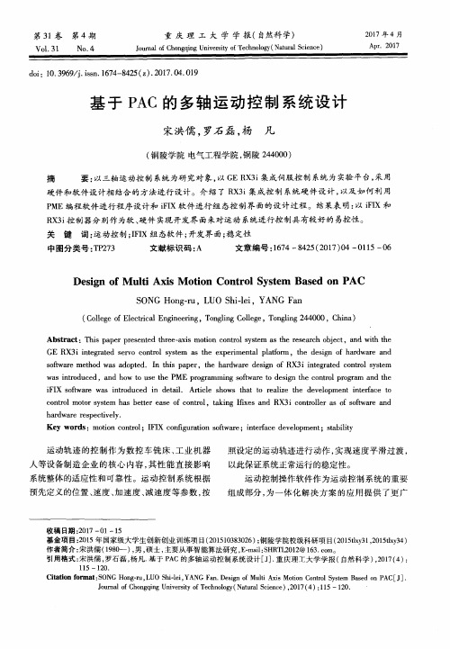
P ME编程软 件进 行程 序设计 和 i F I X软件进 行 组 态控 制界 面的设 计过 程 。结 果表 明 : 以i F I X和
R X 3 i 控制器分别作为软、 硬件 实现开发界面来对运动 系统进行控制具有较好 的易控性 。
关 键 词: 运 动控 制 ; I F I X组 态软 件 ; 开发界 面 ; 稳 定 性
1 系统 总体 结构
控制 系统 包含 硬 件 和 软件 。硬 件 部 分 主要 包
件 制作 运动 控 制 界 面 的监 控 画 面 组态 , 能 起 到 实
时监控 多轴 运 动状 态 的 目的 一 。系 统 总体 构 成
如 图 1所示 。
F S S B线
自 伺服 驱 动 器
自 伺 服 驱 动 器
( 铜 陵学 院 电气 工程 学 院 , 铜陵 2 4 4 0 0 0 ) 摘 要: 以三轴 运动控 制 系统 为研 究对 象 , 以G E R X 3 i 集成 伺服控 制 系统 为 实验 平 台, 采用
硬件 和软件 设计 相 结合 的方 法进 行 设计 。介 绍 了 R X 3 i 集 成控 制 系统硬 件设 计 , 以及如 何 利 用
2 0 1 7年 4月
Ap r .2 0 1 7
d o i : 1 0 . 3 9 6 9 / j . i s s n . 1 6 7 4 - 8 4 2 5 ( z ) . 2 0 1 7 . 0 4 . 0 1 9
汇川多轴控制案例
汇川多轴控制案例汇川多轴控制是一种高精度的多轴运动控制技术,常用于工业自动化设备中。
以下是一个汇川多轴控制的案例:案例名称:自动化生产线中的多轴控制案例描述:某工厂生产线上使用了一套汇川多轴控制系统,用于控制多个运动轴的精确位置和速度,以实现自动化生产线上产品的装配和包装。
系统架构:该多轴控制系统由以下组件组成:1. 控制器:使用汇川的多轴控制器作为主控制器,提供全面的轴控制和运动规划功能。
2. 伺服电机:每个运动轴都配备了高性能的汇川伺服电机,用于提供准确的位置和速度控制。
3. 编码器:每个运动轴都配备了高精度的编码器,用于实时反馈轴的位置,以保证精确的运动控制。
4. 传感器和开关:配备了多个传感器和开关,用于感知生产线上的物料和零件的存在和位置。
5. 人机界面:使用汇川的触摸屏人机界面,用于操作和监控多轴控制系统。
功能实现:1. 运动规划:根据生产线上的产品装配和包装需求,通过人机界面设定每个运动轴的位置、速度和加速度等参数,实现精确的运动规划。
2. 闭环控制:通过实时监测编码器反馈的轴位置信息,并与设定的运动规划进行比较,控制伺服电机的电流和转矩,以实现轴的闭环控制。
3. 运动同步:对于需要多个运动轴同时运动的操作,通过多轴控制器的同步功能,实现多个运动轴的精确同步运动,以保证产品装配和包装的准确性和一致性。
4. 异常处理:通过监测传感器和开关的信号,实时检测生产线上的异常情况,如零件缺失、堵塞等,通过多轴控制器的逻辑控制和报警功能,对异常进行处理和报警,以确保生产线的安全和稳定运行。
通过汇川多轴控制系统的应用,该工厂的自动化生产线实现了高精度的产品装配和包装,提高了生产效率和产品质量,并降低了人力成本和故障风险。
ACS运动控制 引领世界最先进技术
研拓自动化
MPU SPii
研拓自动化
统一的软件平台:SPiiPlus ADK 统一的软件平台:
SPiiPlus MMI SPiiPlus Simulator SPiiPlus FRF SPiiPlus Library PLCopen 文档 课件与例程
研拓自动化
人机接口软件 – SPiiPlus MMI
研拓自动化
SPiiPlus CM
集成了电源和驱动器 研拓自动化
MC4U
用户可配置式控制系统: 控制器,电源, 用户可配置式控制系统: 控制器,电源,驱动器 可配置式控制系统
研拓自动化
HSSI扩展模块 扩展模块
HSSIHSSI-HES HSSIHSSI-IO16 研拓自动化 HSSIHSSI-ED2
C Library
C C++
COM Library
VB LabVIEW
研拓自动化
统一的系统架构:多处理器架构 统一的系统架构:
一个SPii处理器控制两个轴,轴数增加,性能保持不变! 一个SPii处理器控制两个轴,轴数增加,性能保持不变! SPii处理器控制两个轴
研拓自动化
统一的系统架构:多处理器架构 统一的系统架构:
ACS Motion Control
AdvanTofine Automation
研拓自动化
ACS Motion Control
成立时间:1985年 :1985年 产品:高性能多轴运动控制器 : 应用:中高端设备 : 布局
– – –
全球总部:Israel 全球总部: 北美总部: 北美总部:Plymouth, Minnesota 亚洲支持中心: 亚洲支持中心:South Korea
国家实验室智能控制系统多轴运动板手册说明书
Motion ControlNational Instruments548C o n t e n t s a n d O v e r v i e wM o t i o n C o n t r o lContentsMotion Products Selection Guide ..............................550Tutorial . (551)Understanding Motion Basics........................................................551Stepper and Servo Motors..............................................................552Microstepping in Stepper Motor Systems ....................................553Feedback for Closed-Loop Control ................................................554Motion Operation Modes. (555)SoftwareLabVIEW Motion Virtual Instruments............................................556Windows Software for Motion Control..........................................557C Programming for Motion (557)HardwareFlexMotion High-Performance Boards ......................................558Specifications..................................................................................561ValueMotion Boards ....................................................................562Overview..........................................................................................562Stepper Boards................................................................................564Servo Boards ..................................................................................565Specifications..................................................................................566PeripheralsUMI Wiring Interfaces ....................................................................567nuDrive Power Drivers.. (568)Motion ControlOverviewOverviewNational Instruments Phone:(512)794-0100•Fax:(512)683-8411•****************• 549Advanced Motion Performance Using PC-Based StandardsMotion control on the PC is the new standard for intelligent motion integration. The combination of advanced performance, real-time, embedded CPU-based controllers, PCI bus throughput, and Windows graphical programming make PC-based motion the correct choice for powerful, easy-to-use solutions. Motion control on the PC has moved beyond ASCII text programming to interactive graphical interfaces and icon programs on multiprocessor plug-in controller boards, which offload motion tasks from the host PC. These advantages provide seamless integration of motion, vision, data acquisition, and instrument control functions in one system developed using the same software with compatible tools and backed by a uniform worldwide sales and support network. National Instruments motion products are excellent system solutions; they are unsurpassed when used in conjunction with vision and other applications.Motion Products forOEM ApplicationsOEMs need performance, reliability, flexibility, lower cost, and premium support in their motion control products. National Instruments motion control products exceed OEM expectations in all four areas; and as a result, are making equipment manufacturers successful worldwide. Our ValueMotion and FlexMotion products are performance motion controllers with the correct level of compatibility for all OEM applications. Our motion products are manufactured and tested to exceed ISO-9000 quality standards and CE conformance standards.The National Instruments Sales, Support, and Engineering team works closely with OEMs to provide product feature and function enhancement. Our sales people are engineers, trained to make your PC-based measurement and automation application successful.For OEM support well beyondthe industry standard, contact oneof our motion product businessdevelopment managers to discussyour application requirements.What to Look for inMotion Control SystemsA motion control system must make integration of motioncomponents simple while maintaining the performance andflexibility of each component. National Instruments hasdeveloped a premium offering of motion products, and softwaredevelopment tools designed for integration. The connectivitybetween National Instruments motion system componentsfollows industry-standard specifications at each point – controllerto driver, driver to motor, and software to application. Thisconsistency makes your choice of any individual product, or anentire solution, the right choice.To ensure rapid system development, use motion hardwareand LabVIEW graphical programming software for Windowsfrom the same company that designed these tools to worktogether – National Instruments. Spend more time operating yourmotion system and less time figuring out how to configure it. Oursurprisingly simple– yetpowerful – operatorsoftware panels makeit easy to build andrun motionsystems.Motion Control550National InstrumentsPhone:(512)794-0100•Fax:(512)683-8411•****************•Motion ControlTutorialTutorialNational InstrumentsPhone:(512)794-0100•Fax:(512)683-8411•****************•551IntroductionMotion control is a broad term that can be simply defined as the precise control of anything that moves. National Instruments motion control products include PC-based controller boards,wiring, and connectivity devices, power driver units, and software tools and applications. These motion products are optimized for use in test and measurement automation,laboratory automation, industrial control, robotics, material handling, integrated machine vision, CNC machine tool control,and OEM motion applications.National Instruments motion products are designed for powerful yet simple application in both point-to-point and advanced multiaxis coordinated motion systems. The full complement of software tools includes – 32-bit DLL and drivers for C/C++/Visual Basic and LabWindows/CVI in Windows NT/98/95. In addition, the software tools include ready-to-run applications for out-of-the-box motion operation and VIs for graphical object-oriented motion programming with LabVIEW and BridgeVIEW. As a user or integrator of motion control products, it is easy to achieve optimal results and leverage off new standards in motion programming with our PC-based motion control products.PC-Based Architecture for Servo and Stepper ControlServo and stepper motors are widely used for position and velocity control in a variety of electromechanical confie of the PC as an operator interface (HMI), local control host,and remote system controller platform is widely accepted andUsing an intelligent real-time controller board for motion in the PC accomplishes two major objectives in integrating motion,vision, and data acquisition. The first is offloading low-level axis control, closed-loop control, and multiaxis coordination from the host PC; the second is providing a fast, flexible, industry-standard PC-based platform for integrated motion functions.Understanding Motion BasicsA motion control system consists of five major components – the mechanical device being moved, the motor (servo or stepper)with feedback and motion I/O, the motor driver unit, the intelligent controller , and the programming/operator interface software. While solutions exist for a stand-alone distributed motion control and closed architechture motion controllers from other vendors, it is clear that PC-based automation, as well as a focus on PC-based motion solutions and open standards for hardware and software components, is fueling growth in this area.Understanding the requirements of your motion system and the basic technologies for motion are key in selecting products for your application. This tutorial covers motion controller board architecture, servo and stepper motors, motor drivers, feedback for closed-loop control, motion control modes, motion I/O, and industry-standard signals for third-party motion component connectivity. The National Instruments motion products access and control these technologies while emphasizing connectivity between components and graphical tools for development.Motion ControlMotion Control TutorialNational InstrumentsPhone:(512)794-0100•Fax:(512)683-8411•****************•552T u t o r i a lcounter/timer capabilities differently, providing a choice of general-purpose or high-performance solutions. All National Instruments motion controller boards are designed for integrated operation of their dual processor configuration in the LabVIEW and BridgeVIEW graphical programming environments, as well as with LabWindows CVI, C/C++, Visual Basic, and other major development tools.Stepper and Servo MotorsStepper and servo motors are both generic terms covering many technologies. Stepper motors are discrete motion devices that move to positions that relate directly to the number of input control pulses, at a velocity that relates directly to the pulse rate. Servo motors are continuous motion devices that use feedback signals to provide position and velocity control in a closed-loop environment.open-loop servo motor rotates or moves uncontrolled as long as power is applied to it. By implementing a control loop around a servo motor, using a PID controller and feedback from an encoder device mounted on the motor , it is possible to accurately and reliably move to the desired position at well controlled velocities following user-specified motion trajectory paths.All servo motor systems use a motor driver power unit to control the voltage and current that flows through the motor armature and motor windings. The basic principle of motion in servo motors is based on the flow of current through a wire coil,generating a magnetic field that reacts with permanent magnets in the motor to cause attraction and repelling forces that cause movement.M o t i o n C o n t r o lMotion ControlTutorialTutorialNational InstrumentsPhone:(512)794-0100•Fax:(512)683-8411•****************•553DC Brush Servo MotorsThe DC brush servo motor , the simplest servo motor design, is cost effective for its performance and power in general-purpose servo applications. DC brush servo motors are self-commutating motion devices that rotate continuously while current is applied to the motor brush contacts. The current flows through the brushes to the armature and then through the motor coils,creating the magnetic forces that cause motion. Changing the direction of current flow through the motor reverses the direction of rotation. Encoder feedback to the motion board is required to provide accurate control of position and velocity with a DC brush servo motor . Encoders are mounted on the shaft of a motor or on the coupled mechanical unit as a linear or rotary device, directly translating movement into feedback data.Stepper MotorsStepper motors rely on the principle of commutation or alternating magnetic forces, to provide predictable controlled motion. Commutation in motion applications is the controlled sequencing of drive currents and voltages in motor coil windings to provide torque and therefore, movement. In a stepper motor system, individual step signals from a motion control board are converted into an energizing pattern for the motor coils.As the commutation pattern varies, the motor moves from one discrete position to another . When the pattern is held in a single state, the stepper motor holds its position with a known torquefull-step locations of a stepper motor the basic resolution of the motor to as 1.8 degree/step motor revolution per minute (rpm).Microstepping in Stepper Motor SystemsAdvanced stepper motor driver technology provides a capability known as microstepping. Microstepping is based in the stepper motor driver component. It provides for the predetermined subdivision of each full step into microsteps by proportioning the currents in each coil to produce carefully balanced electromagnetic locations between the full steps. To quickly review the technology of microstepping, sine and cosine proportioned values of current are carefully sent to particular motor coils, resulting in the simulation of interim microstep locations. The advantage of microstepping is multiplication of the number of steps per revolution, thereby increasing the resolution of a stepper motor system. Additionally, because more steps are provided, the movement between steps is smaller and the resulting step motion is typically smoother. Microstepping technology is widely accepted and fully implemented in all National Instruments stepper control and driver products.Because stepper motion is controlled by the generation of step pulses from the controller board, it is clear that the stepper motor controller must carefully control the number of pulses (position), the frequency of the pulses (velocity), and the rate of change of frequency (acceleration/deceleration). This process is referred to as trajectory control, where the trajectory is the predictable path of speed changes that the motor undergoes as it moves from its starting position to its desired end position through its profile or as it runs continuously at desired velocities.Motion ControlFigure 3. Stepper Motor Controllers and nuDrives Support MicrosteppingMotion Control TutorialNational InstrumentsPhone:(512)794-0100•Fax:(512)683-8411•****************•554T u t o r i a lFeedback for Closed-Loop Motion ControlMotion systems use feedback signals to provide closed-loop control of position and velocity. Although feedback is optional in stepper motor systems, servo motor systems require feedback for proper control, operation, accurate motor position, and velocity maintenance. The most common feedback used with intelligent motion control boards is quadrature incremental encoder feedback.Feedback devices provide signals that convey position and velocity data to a motion controller . The signals are converted on the motion controller into count values that correspond to position. Position values, measured over fixed periods of time,Quadrature Encoder FeedbackQuadrature incremental encoders are optoelectronic feedback devices that use a patterned optical mask and optointerrupter-LED source/transistor detector pairs to generate two digital output waveforms, where the pulse location of the waveforms are 90 degrees out of phase with each other . This 90 degree phase difference in the waveforms (quadrature) is used by the encoder input circuitry to enhance the resolution of the position count value and to determine the direction of motion. If the A phase signal leads or comes before the B phase signal, then motion direction is considered clockwise or forward. For the opposite phasing, the direction is considered counter-clockwise or reverse.The quadrature encoder input circuits decode the phasing of the signals and count the quadrature pulses to derive position information. The position count value is maintained in a 32-bit register , providing more than 4 billion position locations.The detector circuits for encoder feedback on the motion controller boards incorporate digital signal filtering techniques to avoid deception by noise pulses or erroneous data that does not fit the quadrature model.Analog FeedbackAlthough quadrature encoder feedback is the most common type used, you can use analog feedback to provide the same position and velocity data. If an analog input signal is measured and converted by an ADC on the motion board, the analog value generates a corresponding digital value. This value is then used as position data and the overall range of available positions is determined from the resolution of the ADC. Analog feedback,.acceleration phase. Switching power supplies typically suffer from output shutdown when the motor driver attempts to draw the extra current that it requires during acceleration.National Instruments motion control products provide two different solutions for motor driver configuration. The nuDrive units are fully enclosed motor driver subsystems with a single cable connection from the motion control board. nuDrives include the appropriate motor driver types per axis, for small DC brush type servo or stepper motors, along with bulk DC power supplies specifically designed to provide the voltage and currents demanded by these drivers. Additionally, nuDrive units incorporate all of the necessary low-voltage power supplies,wiring connectivity, signal conditioning, and monitoring that are appropriate for motion system integration with encoders, limit switches, and other motion I/O devices.If nuDrive voltage and current capabilities do not meet the requirements of a specific motor, it is simple to connect to third-party motor drivers using a universal motion interface module (UMI).M o t i o n C o n t r o lMotion ControlTutorialTutorialNational InstrumentsPhone:(512)794-0100•Fax:(512)683-8411•****************•555The UMI accepts the single cable connection from the motion controller board and breaks out the motor , encoder , limit, and motion I/O signals on a per-axis basis into separate pluggable screw terminal connections. The UMI provides all of the onboard signal conditioning and monitoring found in a nuDrive. Because the motion controller board outputs industry-standard signals,through the UMI, this configuration provides for limitless connectivity. You can use any size or type of motor , as long as the associated driver unit is compatible with the standard control and feedback signals.Motion Operation ModesPC-based servo and stepper controller boards offer a wide variety of operation modes. The modes listed provide operational features and functionality at a high level, making it simple to solve motion applications. Access these standard operation modes in a fully integrated motion system with powerful software tools. Easy-to-use Windows software, drivers, and Motion VIs make mode operation, parameter loading, and status display a snap. Motion is controlled in absolute or relative mode, and you can use all position breakpoint, position value capture, and status functions.Point-to-Point Position ModeIn point-to-point mode, each axis is indepen-dently programmed with motion profile parameters. Values for velocity, acceleration,deceleration, S-curve, and target position are loaded prior to a start command.Linear Vector Interpolation ModeIn linear vector interpolation mode, you canassign axes to a vector space; motion control ofthe axes accurately follows the desired vector path, at the programmed vector velocity,acceleration, and deceleration values. Vector spaces can contain one, two, or three axes and you can synchronize multiple vector spaces. You can also sequence and blend motion profiles for smooth transition.Electronic Gearing, Master/Slave ModeIn electronic gearing and master/slave modes,you can configure any axis or axes to run at a gear ratio to any master axis. The master axis could be encoder feedback only, or a motor under closed-loop control. These powerful gearing modes are used for coil winding, flying cutoff, rotating knife, high-speed labeling, and all other geared and slaving applications.Circular, Spherical, and Helical Interpolation ModesIn these modes, the motion parameters describing arcs, vector velocity, accel/decel,radius, start angle, and target angle are loaded before the move is started. For helicalinterpolation, the target height (Z) is also loaded and for spherical interpolation, two start angles and two target angles are specified. Motion will accelerate to the vector velocity while following the path indicated by target angles and height.S-curve on a motion profile is controlled by separate accel-eration and deceleration smoothing (jerk-limit) factors.Velocity Profiling ModeThis mode provides a user-programmed acceleration to a desired target velocity that is accurately maintained until a new target velocity value is loaded. You can change velocity on the fly.Jog Modeparameter is updated on the fly or a stop command is issued.Registration ModeRegistration is used to capture the exact position when the high-speed capture input signal transitions. The high-speed capture eliminateslatency and provides precise motor control athigh velocities. High-speed capture input position values are automatically combined with a registration move; and the new motion can be completed autonomously.Homing ModeHoming is accomplished through the Findindex (marker) pulse of the feedback encoder device, and then moves to the index offset position. Homing mode is used during system setup and initialization.Motion Control。
:ACS运动控制
研拓自动化
Firmware - SP程序 程序
编码器反馈值处理 给定值精插补 位置环控制算法 速度环控制算法 电流环控制算法
研拓自动化
应用程序开发
研拓自动化
ACSPL+开发环境 开发环境
研拓自动化
ACSPL+基本特性 基本特性
高级语言, 高级语言,拥有丰富的指令集 强大的运动控制指令 64位浮点运算,丰富的数学函数 位浮点运算, 位浮点运算 复杂的数学表达式 多任务: 个程序区 可以10个程序同时运行 个程序区, 多任务:10个程序区,可以 个程序同时运行 编译执行,类似于 编译执行,类似于C++ 执行时间确定:每个MPU周期执行 周期执行1~10行 执行时间确定:每个 周期执行 行 每行程序可以包含多个语句 自动执行子程序(Autoroutine) 自动执行子程序 大容量: 大容量:128Mb RAM, 128Mb Flash 支持一维和二维数组,数组最大容量为10万 支持一维和二维数组,数组最大容量为 万 支持全局变量, 支持全局变量,每个程序都可访问
研拓自动化
MPU SPii
研拓自动化
统一的软件平台:SPiiPlus ADK 统一的软件平台:
SPiiPlus MMI SPiiPlus Simulator SPiiPlus FRF SPiiPlus Library PLCopen 文档 课件与例程
研拓自动化
人机接口软件 – SPiiPlus MMI
研拓自动化
Q&A
研拓自动化
Thanks!
研拓自动化
�
SIN-COS编码器细分器
– –
65536倍 16位分辨率 位分辨率, 4 ~ 65536倍,16位分辨率,2.5MHz 可达到亚纳秒级的分辨率
- 1、下载文档前请自行甄别文档内容的完整性,平台不提供额外的编辑、内容补充、找答案等附加服务。
- 2、"仅部分预览"的文档,不可在线预览部分如存在完整性等问题,可反馈申请退款(可完整预览的文档不适用该条件!)。
- 3、如文档侵犯您的权益,请联系客服反馈,我们会尽快为您处理(人工客服工作时间:9:00-18:30)。
ACS多轴运动控制系统应用
为了满足当今半导体产业的最高的多轴自动化应用的需求,工程师们转而朝向把最好的集成和基于网络的控制属性的运动控制平台方向。
许多先进机器的控制平台,即基于网络和集中控制开始看到从自动化领域里广泛的实践,因为它们需要大量的处理能力和通信带宽,这在几年前微处理器和网络技术是无法实现的。
在高端多轴自动化行业很多人知道,从20 世纪90 年代以来的集中式多轴控制器的好处。
使用中央高速处理器,处理协调多轴运动控制已被证明为确定性数字伺服控制的有效架构,使最快的更新率和精密的同步。
另外,网络结构,如CANopen 网络的,已经成功地实践在了太阳能电池板划线,半导体制造和通用自动化应用中等需要可扩展性,开放的多厂商和设备,对成本控制敏感的系统设计中的运动控制领域。
网络标准也一直在不断发展,并且不断提高的带宽和可靠性。
现在,随着基于以太网的实时工业网络,如EtherCAT 技术–决定性的实时工业网络具有足够的带宽以支持高性能协调很多个运动控制轴和I / O,是有可能的实现机器控制控制解决方案,他具有集中式和基于网络控制的最佳品质。
下面是三个最近需要高度的协调和精确的多轴运动控制案例,每一个展现着对控制系统的独特的挑战和极限。
1。
太阳能电池板划线和光学检测设备扁平面板和薄片的激光划线经常需要用到极其高性能的运动控制,包括高的速度和加速度,高度协调的多轴激光路径,晶圆检查和及其最小的运动误差最大化光伏(PV)的晶圆密度或解决最小的缺陷。
大尺寸面板占用面积超过一平方米以上;而且,由于面板增加的尺寸的规模,导致的机器设备的复杂性和多轴数和运动的性能和功率的需求。
最近,太阳能面板板划线设备和检测设备的制造商在设计一条15 轴的生产线的控制系统是遇到了很多挑战。
有些版本的机器还使用了其他辅助轴和I / O 设备。
一个集中。