Patch clamp lecture contents
膜片钳实验技术入门---基本原理与操作
膜片钳实验技术入门------基本原理与操作关兵才 李国华 刘理望按:本文乃于2003年根据较旧型号的仪器写成,后被《机能实验科学》 (郑先科主编,北大医学版,2006)收入。
因新旧仪器基本原理和操作步骤大同小异,现对原文略作修改和标注,供同学们参考。
【实验目的】1. 了解膜片钳技术的基本原理和操作。
2. 初步学习电压依赖性离子通道电流的基本记录方法。
【实验原理】一、膜片钳技术原理简介膜片钳(patch clamp)是一种主要用于检测细胞膜离子通道活动的电生理技术,按工作方式可区分为电压钳(voltage clamp)和电流钳是最基本的工作方式,即对细胞膜电位进行人为控制,如将膜电位钳制于某一固定水平,或在此基础上再施以阶跃(step)式或斜坡式(ramp)电压刺激,同时记录跨膜电流,从而分析细胞膜通道的活动。
电流钳即人为控制经微电极对细胞进行注射的电流(等于离子通道电流与细胞膜电容电流之和),同时记录膜电位及其变化。
若注射电流为零即常用的零位钳流,用于测量细胞膜静息电位,若注射方波脉冲刺激电流,用于诱发、观测动作电位。
另外,膜片钳技术还常用于观测细胞膜电容, 从而推测分泌细胞的活动情况。
下面主要介绍其电压钳工作方式的基本原理。
(注:在电生理资料中,因通常将细胞外液和记录系统的“地”点相连作为参考点即零电位点,所以电位和电压两个概念经常混用。
)根据膜片钳实验中受检细胞膜的型式(configuration)不同,又可将膜片钳分为全细胞式(whole-cell)、细胞贴附式(cell-attached 或on-cell)、内面朝外式(inside-out)、外面朝外式(outside-out)等四种模式。
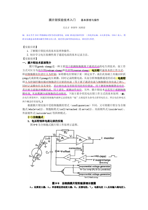
(一)全细胞式1.电压钳制和电流记录的实现图9-9为全细胞式膜片钳工作原理示意图。
图9-9 全细胞膜片钳实验原理示意图A1:运算放大器;A2:单倍增益差动放大器;R f:反馈电阻;V p:电极电位(A1反向输入端电位);V c:A1同向输入端电位;C in:输入端杂散电容;C p:电极电容;Rs:串联电阻;C m:细胞膜电容;R m:细胞膜电阻;E m:细胞膜内在电位(指钳压时的细胞膜诸通道状态决定的内在Goldman-Hodgkin-Katz平衡电位);V o:A2输出端电位;V-offset:偏移电位补偿电位;C c:用于电容补偿的电容;V c(app):表观钳制电压即欲施加于受试膜片的电压;图中⊕和表示求和电路将充有电解质溶液的玻璃微电极(glass microelectrode或 recording pipette)利用负压紧密吸附于细胞表面,形成吉欧即千兆欧(109Ω)级高阻封接,进一步对微电极内施加负压、将放大器(以下简称运放)A1在深度负反馈工作状态下的“虚短路(virtual short circuit)”原理实现,即只要A1工作于线性范围内,其反向输入端的电位V p总是等于同向输入端的电位V c,这两个输入端之间虽非短路却类似于短路。
膜片钳实验技术(高级生理课程,201310)

Sutter公司微电极拉制器
P-97
P-2000
日本成茂公司微电极拉制器和抛光仪
软件系统:目前的数据采集和分析软件系统主要是 Axon公司的Pclamp软件和HEKA公司的Patch Master 软件。在实验后期文章发表中还涉及到一些图形处 理软件,如Origin等软件。
MDC公司Pclamp采集和分析软件
膜片钳放大器的工作模式: (1).电压钳模式:在钳制细胞膜 电位的基础上改变膜电位,记 录离子通道电流的变化,记录 的是诸如通道电流;EPSC;IPSC 等电流信号。是膜片钳的基本 工作模式. (2).电流钳模式:向细胞内注入 刺激电流,记录膜电位对刺激 电流的反应。记录的是诸如动 作电位,EPSP;IPSP等电压信号。
AXON200B
MultiClamp700B
EPC10
数据采集、分析系统
光学部件和光电接口:膜片钳实验是一 个微操作实验,需在显微镜下进行玻璃 电极和细胞的封接,因此需要高质量的 显微镜和成像系统,如果所用的细胞是 培养的单个细胞,需要一台倒臵相差显 微镜,而如果所用的标本是脑片或其他 组织片,所用的光学系统必须是红外微 分干涉差成像系统,这样才能“看”到 组织中的单个的细胞,才能在可视条件 下进行组织膜片钳的操作。
膜片钳记录模式
————————
细胞吸附模式
Cell-attached mode; on-cell mode 细胞内环境保持正常条件下可对离子通道的活 动进行观察记录。 到达与电极接触的膜片外部,如果刺激浴液中 加入刺激物质不能有效,则说明刺激物质是经 过细胞内第二信使介导间接起作用。 不能人为直接控制细胞内环境条件,不能确切 判定细胞内电位,不清楚膜片上的实效电位。
+
膜片钳patch-clampppt课件
心肌钠通道,激活所需要的电压高、失活速度快、 引起动作电位(action potential, AP)的0期去极化 。
三、离子通道的分子结构及门控机制
1.电压门控离子通道的分子结构 钠、钙和钾电压门控通道在分子结构上有许多相似之处,离
子通道蛋白是多亚基(subunits)构成的复合体。其中,构成孔道部 分的是α亚基。各种电压依赖的离子通道的α亚基均在膜上形成四个 跨膜区(D1-D4),钠、钙通道的四个跨膜区由共价键连接成四倍体 位于同一肽链,整个亚基只有一个N-末端和一个C-末端。钾通道的 α亚基只有一个跨膜区,功能性钾通道是四个α亚基由非共价键连接 而成的四聚体。每个跨膜区由6个呈α螺旋式的跨膜片段 (transmembrane segmants, S1-S6)及其间的连结肽链所组成。连接 S5-S6的肽链部分贯穿于膜内,是形成亲水性孔道而有选择性地让离 子通过的部分,称为孔道区(pore region)或P区。另一个重要的肽 段是S4 , S4共带4~8个正电荷,当膜电位变化时,S4螺旋构型即发 生变化,通道开放,故S4被称为电压门控性离子通道的电压感受器 (voltage sensor)。
2.内向整流钾通道的分子结构
具有内向整流性钾通道,主要指KIR,KACh, KATP等,他们与Kv通道一样由4个α亚单位对称 排列而成,但每个α亚单位只有2个跨膜螺旋片 段(M1和M2),两者由H5连接。
3.离子通道的门控机制
电压依赖性钠通道受膜电位的影响,在 不同电压影响下,通道蛋白发生构象变 化而使通道不断转换于静息态(resting state)、开放状态(open state)和失活 状态(inactive state)。
膜片钳与ltp-ppt课件

LTP原理
电生理记录上反映为EPSP 或EPSC幅度的增加,即 LTP。
2211
记录电极
~
海马脑片LTP
海马脑片上电极的放置
2222
大鼠体重:180-240g
在体LTP
刺激电极: 采用针灸针,多为 双极电极 定位坐标(mm):AP 8,LM 4, DV 3.2-3.5 记录电极:采用针灸针,为 单极电极 定位坐标(mm): AP 4,LM 2, DV 3.2-3.5
1144
膜片钳技术的应用
细胞特性的研究 离子通道的鉴别 电压门控性离子通道的动力学特性研究 突触联系、突触传递的研究 疾病机制研究 药物筛选 其他
1155
突触可塑、学习记忆及其机制的研究
长时程增强(LTP)是评价学习记忆及其突触可塑的常用的电 生理指标。目前,海马脑片离体实验己经广泛用于学习记忆方面 的研究,利用膜片钳技术记录脑片LTP,可在细胞水平研究学习 记忆的机制。 当今从不同方面对突触LTP与学习记忆的关系进行了大量的研 究,其结果大致可概括为: 影响LTP的因素确实对学习研究过程产生明显的影响 影响学习过程的因素也影响LTP形成 诱导海马脑区的LTP形成可提高学习记忆活动,学习过程中伴 有海马脑区LTP的形成。
(1)一般电学性质:通过I-V关系计算单通道电导,观察通道有无整流。通过离子选 择性、翻转电位或其它通道激活条件初步确定通道类型。 (2)动力学:开放时间、开放概率、关闭时间、通道的时间依赖性失活、开放与关闭 类型(簇状猝发样开放与闪动样短暂关闭),化学门控性通道的开、关速率常数等。 (3)通过对全细胞激活曲线或失活曲线的分析,可得到半数激活或失活电压Vh及斜率 因子K。 (4)药理学:阻断剂、激动剂或其它调制因素对通道活动的影响。 (5)综合分析得到最后结论。
patch clamp膜片钳技术的原理和应用(超全的哦)
第二部分
一:应用学科
膜片钳技术的应用
膜片钳技术发展至今,已经成为现代细胞电生理的常规 方法,它不仅可以作为基础生物医学研究的工具,而且直 接或间接为临床医学研究服务, 目前膜片钳技术广泛应用于神经(脑)科学、心血管科 学、药理学、细胞生物学、病理生理学、中医药学、植物 细胞生理学、运动生理等多学科领域研究。 随着全自动膜片钳技术(Automatic patch clamp technology)的出现,膜片钳技术因其具有的自动化、高 通量特性,在药物研发、药物筛选中显示了强劲的生命 力。
5.对药物作用机制的研 在通道电流记录中,可分别于不同时间、不同部位(膜内 或膜外)施加各种浓度的药物,研究它们对通道功能的可 能影响,了解那些选择性作用于通道的药物影响人和动物 生理功能的分子机理。这是目前膜片钳技术应用最广泛的 领域,既有对西药药物机制的探讨,也广泛用在重要药理 的研究上。如开丽等报道细胞贴附式膜片钳单通道记录法 观测到人参二醇组皂苷可抑制正常和“缺血”诱导的大鼠大 脑皮层神经元L-型钙通道的开放,从而减少钙内流,对缺 血细胞可能有保护作用。陈龙等报道采用细胞贴附式单通 道记录法发现乌头碱对培养的Wistar大鼠心室肌细胞L-型 钙通道有阻滞作用。
膜片钳技术原理与基本操作

膜片钳技术原理与基本操作(总7页)-本页仅作为文档封面,使用时请直接删除即可--内页可以根据需求调整合适字体及大小-膜片钳技术原理与基本操作1976 年Neher 和Sakmann 建立了膜片钳技术(Patch clamp technique), 这是一种以记录通过离子通道的离子电流来反映细胞膜上单一的或多数的离子通道分子活动的技术。
1981年Hamill, Neher等人又对膜片钳实验方法和电子线路进行了改进,形成了当今广泛应用的膜片钳实验技术。
该技术可应用于许多细胞系的研究,也是目前唯一可记录一个蛋白分子电活动的方法,膜片钳技术和克隆技术并驾齐驱给生命科学研究带来了巨大的前进动力,这一伟大的贡献,使Neher和Sakmann获得1991年诺贝尔医学与生理学奖。
—、膜片钳技术的基本原理二、用一个尖端直径在〜um的玻璃微电极接触细胞膜表面,通过负压吸引使电极尖端与细胞膜之间形成千兆欧姆以上的阻抗封接,此时电极尖端下的细胞膜小区域(膜片,patch)与其周围在电学上分隔,在此基础上固定(钳制,Clamp)电位,对此膜片上的离子通道的离子电流进行监测及记录。
三、基本的仪器设备有膜片钳放大器、计算机、倒置显微镜、示波器、双步电极拉制器、三轴液压显微操纵器、屏蔽防震实验台、恒温标本灌流槽、玻璃微电极研磨器。
膜片钳放大器是离子单通道测定和全细胞记录的关键设备,具有高灵敏度、高増益、低噪音及高输入阻抗。
膜片钳放大器是通过单根电极对细胞或膜片进行钳制的同时记录离子流经通道所产生的电流。
膜片钳放大器的核心部分是以运算放大器和反馈电阻构成的电流-电压(I-V)转换器,运算放大器作为电压控制器自动控制,使钳制电位稳定在一定的水平上。
四、二、操作步骤2.膜片钳微电极制作(1)玻璃毛细管的选择:有二种玻璃类型,一是软质的苏打玻璃,另一是硬质的硼硅酸盐玻璃。
软质玻璃在拉制和抛光成弹头形尖端时锥度陡直,可降低电极的串联电阻,对膜片钳的全细胞记录模式很有利;硬质玻璃的噪声低,在单通道记录时多选用。
膜片钳记录法
膜片钳记录法(Patch Clamp Recording)是一种生理学实验技术,用于测量细胞膜离子通道或受体的电生理特性和活动。
该技术的基本原理是使用微型玻璃电极将一个非常小的玻璃管(称为膜片)贴附到单个细胞的表面上,从而形成一个微小的、高阻抗的突触点。
然后在膜片和细胞膜之间形成一个密封,并使用微电极或电极芯片记录跨越这个突触点的电位变化。
这种技术可以测量非常小的电流变化(尤其是亚毫安级别),因此非常适合研究离子通道和受体的活动。
通过控制细胞环境的情况,例如改变温度、pH值或添加化学物质,可以进一步调节离子通道和受体的电生理属性及其响应模式。
这种方法还可以用于研究各种细胞类型的电生理特性,包括神经元和心肌细胞等。
膜片钳记录法是一种十分精密的技术,在操作过程中需要非常小心谨慎,以避免损坏细胞或膜片。
同时,该技术需要一定的专业知识和设备支持,因此通常由有经验的生理学家和技术人员来执行。
总之,膜片钳记录法是一种重要的电生理技术,已经成为研究离子通道和受体的电生理学特性的关键工具之一,对于揭示神经、心血管等多种疾病的发病机制和治疗方法也具有重要意义。
Thorlabs Manual Patch-Clamp Micromanipulators说明书
Hide OverviewCommon Micromanipulator SpecificationsClick to EnlargeFeaturesThese adapters allow for more flexibility during experiments and minimize mechanical clashing with microscopy objectives or other experimental apparatus. A close-approach headstage and pipette adapter is also available that allows pipettes and headstages to be positioned closer to a sample without interference from the micromanipulator.Piezoelectric ControlPiezoelectric control is used to achieve superior positioning compared to hydraulic manipulators, mechanical manipulators, or motorized leadscrews. Piezoelectric control provides smooth and predictable movement with no backlash and minimal drift (<1 µm/hr with temperature control). An axis control unit is included with each piezoelectric micromanipulator (see the provides a displacement of 150 µm or 300 µm (depending on model). Three turns on the control unit corresponds to the full piezo travel range, resulting in a O V E R V I E WManual Micromanipulator Assemblies with Precision Control Ideal for Gibraltar™ Microscope PlatformsPosition Pipette or Electrode Along Three Different Axes ► ►►Application IdeaTwo PCS-5400 Micromanipulators Mounted onOur Gibraltar GMHB-BX PlatformPCS-5300PCS-5400 - July 16, 2021Item # PCS-5400 was discontinued on July 16, 2021. For informational purposes, this is a copy of thewebsite content at that time and is valid only for the stated product.Hide Custom OptionsClick to EnlargeMicromanipulator AssemblyClick to EnlargeAdjustable Stop Ring with Pin andBrass Block with Locking Thumbscrew These micromanipulators include two adjustable stop rings that allow a user to repeatedly and accurately set the approach angle and horizontal rotational orientation (see image to the left). Once an appropriate angle or rotation is established, tighten the thumbscrew on the brass block to lock the mount in position. Loosen the two setscrews on either side of the pin using a 0.05" (1.3 mm) balldriver or hex key. Rotate the ring until the protruding pin is in physicalcontact with the brass block. To lock the ring, tighten the exposed setscrew, then loosen the thumbscrew to allow the The adjustable stop rings in combination with the headstage adapter or pipette holder (sold separately below) provide a convenient mechanism for quickly changing pipettes and returning to the last position during an experiment, minimizing position readjustments and increasing efficiency. To do this, the user can set the adjustable stop ring to remember the approach angle and rotation, move the pipette away from the sample using the slide assembly on the adapters,Click to Enlarge Axis Control UnitClick to Enlarge 60 V Power SupplyOur micromanipulator power supply provides a regulated, low noise, 60 V output for the axis control unit. Two voltage outputs enable the power supply to regulate two axis control units. This allows the user to run two micromanipulation Custom Options tab for more information).Click to EnlargeThe PCS-5200N Connected to Included Axis Control UnitPower Supply Coarse Travel PCS-520N No S T O M O P T I O N SCustom Options for Manual MicromanipulatorsClick to EnlargeThe PCS-500-SSH can be mounted for steep (left) or shallow (right) approachangles.Click to EnlargePCS-500-SSH Headstage Adapter ComponentsClick for Details The PCS-AXN-ADP Close-Approach Adapter Secured to aMicromanipulator Headstage Adapter and Pipette Holder MountsMount Headstages or Pipettes onto Manual or Motorized Micromanipulator Assemblies Three Options Available:PCS-500-SSH: Two Dovetails with a Mounting Platform for Large Axon or HEKA HeadstagesPCS-AXN-ADP: Single-Dovetail, Close-Approach Adapter for Smaller Headstages MIS-PHM: Two Dovetails with Pipette Mount that Provides 360° Rotational PositioningSmooth Motion Allows Orientation of Headstage or Pipette at Very Steep (>45°) or Very Shallow (<25°) AnglesMultiple Mounting Position Options Provide Extra Clearance Near ObjectivesThese adapters for the micromanipulator assemblies provide a flexible platform for mounting a headstage or pipette; see the table below for details. Each adapter To install the adapter, attach the mounting plate to the micromanipulator using the included 4-40 screws (3/32" hex). Secure the slide assembly in one of the dovetail grooves by installing the clamping plate with the included 2-56 cap screws and 5/64" (2 mm) hex key. The user can loosen the clamping plate and position the entire slide assembly; this determines the stop locations that correspond to the fully extended and fully retracted positions of the pipette. At least 1" of the slide assembly should be held by the clamping plate to ensure stability of the mount. To adjust the slide position, turn the locking handle to loosen, then move the slide to the desiredMicromanipulatorClick to Enlarge MIS-PHM Pipette Holder Mount Securedto MicromanipulatorItem #。
patch-clamp recording-1
The Voltage-Gated Calcium Channels
N- and L-type macroscopic Ca2+ currents
Hammond C., Cellular and Molecular Neurobiology, 2001, Acadmic Press
+40mV
LIU Yong
Background Whole-cell currents Single-channel recording
Background: receptors/ion channels
Voltage-gated channels
Asymmetric distribution of ions across the plasma membrane
Hypoxia Shifts the Sensitivity of NMDA Receptor Inhibition toward Lower Concentrations of NO
Cysteine Residues of the NR2A (C399) Subunit Involved in Hypoxic Enhancement of SNOC Inhibition
metal electrode
Adapted from ECB Fig 12-22
I vs. V curves
Ligand-gated ion channels
Voltage-gated ion channels
Patch Clamp
The patch clamp consists of an electrode inside a glass pipette. The pipette, which contains a salt solution resembling the fluid normally found within the cell, is lowered to the cell membrane where a tight seal is formed. When a little suction is applied to the pipette, the "patch" of membrane within the pipette ruptures, permitting access to the whole cell. The electrode, which is connected to specialized circuitry, can then be used to measure the currents passing through the ion channels of the cell. Furthermore, we can use our electrical circuitry to "clamp" the membrane potential to any voltage that we desire: very handy when measuring the activity of voltage-dependent channels.
膜片钳技术
膜片钳技术摘要:80年代初发展起来的膜片钳技术(patch clamp technique)为了解生物膜离子单通道的门控动力学特征及通透性、选择性膜信息提供了最直接的手段。
该技术的兴起与应用,使人们不仅对生物体的电现象和其他生命现象更进一步的了解,而且对于疾病和药物作用的认识也不断的更新,同时还形成了许多病因学与药理学方面的新观点。
关键字:膜片钳细胞膜电位膜片构型通道膜片钳技术是一种以记录通过离子通道的离子电流来反映细胞膜单一的或多个的离子通道分子活动的技术。
它和基因克隆技术(gene cloning)并架齐驱,给生命科学研究带来了巨大的前进动力。
膜片钳技术发展历史1976年德国马普生物物理化学研究所Neher和Sakmann首次在青蛙肌细胞上用双电极钳制膜电位的同时,记录到ACh激活的单通道离子电流,从而产生了膜片钳技术。
1980年Sigworth等在记录电极内施加5-50 cmH2O的负压吸引,得到10-100GΩ的高阻封接(Giga-seal),大大降低了记录时的噪声实现了单根电极既钳制膜片电位又记录单通道电流的突破。
1981年Hamill和Neher等对该技术进行了改进,引进了膜片游离技术和全细胞记录技术,从而使该技术更趋完善,具有1pA的电流灵敏度、1μm的空间分辨率和10μs的时间分辨率。
1983年10月,《Single-Channel Recording》一书问世,奠定了膜片钳技术的里程碑。
Sakmann 和Neher也因其杰出的工作和突出贡献,荣获1991年诺贝尔医学和生理学奖。
膜片钳技术基本原理与特点膜片钳技术本质上也属于电压钳范畴,两者的区别关键在于:①膜电位固定的方法不同;②电位固定的细胞膜面积不同,进而所研究的离子通道数目不同。
电压钳技术主要是通过保持细胞跨膜电位不变,并迅速控制其数值,以观察在不同膜电位条件下膜电流情况。
因此只能用来研究整个细胞膜或一大块细胞膜上所有离子通道活动。
- 1、下载文档前请自行甄别文档内容的完整性,平台不提供额外的编辑、内容补充、找答案等附加服务。
- 2、"仅部分预览"的文档,不可在线预览部分如存在完整性等问题,可反馈申请退款(可完整预览的文档不适用该条件!)。
- 3、如文档侵犯您的权益,请联系客服反馈,我们会尽快为您处理(人工客服工作时间:9:00-18:30)。
Lecture 2: Patch Clampingeful modifications of Ohm’s law for calculating the amount of current flowingthrough a membrane and the conductanceA.Ohm’s law is: V = IR1.Where2.V = voltage3.I = current4.R = resistancea)The inverse of resistance is conductance (abbreviated as a “g”[some sources use a capital G as the abbreviation])B.Ohm’s law using conductance:1.Solving for I:C.The voltage that produces currents in cells is the difference between anion’s equilibrium potential & the membrane pot ential (V m– E x), where “x”indicates the ion in question1. Substituting into Ohm’s law: I x = g x (V m– E x)2. Note that for a typical negative resting potential that if E x isnegative (like for K+) I x is positive, while if E x is positive (like forNa+ or Ca++) I x is negative3. This is very important when considering voltage clampingD.Rearrange the above equation to solve for conductance:1. This is useful during patch clamping because different channelswill have different conductancesa) You determine ion selectivity by either changing theequilibrium potentials or using selective toxins that blockcertain classes of channelsb) There are often several different channels for a particularion(1)You can tell them apart by their conductancesII.We can observe the behavior of individual channels in biological membranes by use of a technique called patch clampingA.Start with an electrode similar to a glass microelectrode except tip is maybe 1-3 μm in diameter1.Tip is firepolished to make sure it’s very smoothB.Place electrode tip on clean surface of a cell1.Apply suction & if lucky a gigohm (109Ω) seal will developC.The membrane encircled by the tip of the electrode is called a patchD.Because of gigohm seal, very little current generated in the patch will leakout between the electrode and the membrane1.Most of the current is then forced to flow through the electrodeE.In any one patch there one or a few channelsF.During patch clamping the potential across the membrane is held constant1.This allow the measurement of the amount of current flowingthrough the channela)This technique is called voltage clamping(1)The term “clamp” refers to keeping that parameterconstant(a)In voltage clamping, we keep the voltage constantand measure the current flowing through themembraneG.There are several configurations for patch clamping1.Cell-attached patch (single channel resolution)2.Excised inside-out patch (single channel resolution)a)After forming a cell-attached patch, the electrode is pulledaway from the cell(1)Eventually the membrane will separate from the cell andform a vesicle(2)Vesicle is either exposed to air or a low calcium saline(a)This ruptures the vesicle outside the pipette(3)The pipette is left with a single layer of membranespanning the opening(a)The membrane surface inside the pipette was theoutside surface of the cell(b)The surface exposed to the outside saline was thecytoplasmic face of the membrane3.Whole cell clampa)Start with cell attached configuration(1)Apply suction in pipette until membrane is rupturedb)Records are very similar in appearance to traditional voltageclamping because the activity of many channels is recordedc)Advantages(1)Often technically easier than traditional voltage clampingd) A variation on this is the perforated patch, which uses a pore-forming compound such as nystatin(1)Advantage is that the pores are small enough that most ofthe intracellular stuff stays in the cell (prolongs channel “life”)4.Excised outside-out patch (single channel resolution)a)Start with whole cell clamp configurationb)After rupture of membrane, electrode is pulled away from celluntil membrane separates(1)Ruptured membrane will seal so that outside membranesurface in on outside of electrode(a)Membrane surface inside electrode is cytoplasmicfaceH.Patch clamp records show the following characteristics1.Channel opens or activates abruptlya)Indicate opening and closing(1)Explain inward current and downward deflection2.Channel shows constant open conductance3.Channel closes or inactivates abruptly4.The open time varies5.Channels often show flicker where they briefly open or close6.Channels can flicker between the open state and partially closedstatesa)This indicates that there may be substates between fully openand fully closed states7.The noise level during the open state is higher than during theclosed statea)Greater noise probably the result of slight variations in thenumber of ions passing through the channelI.Channel opening is stochastic1.When the individual channels open is random & not predictableJ.Channel gating is Markovian1.The probability of a channel transition is always constant – it doesnot depend on channel history (what it has just been doing has no impacton what it’s about to do)a)Applies to both opening & closingK.The amount of open and closed time of the channel can depend on:1.The voltage the patch is clamped at (for voltage sensitive channels)2.For chemically sensitive channels, the presence and amount of thechemicala)For example, the chemical could be a neurotransmitter, asecond messenger or the ionic composition of the medium L.Open probability time:M.Channels can have different kinetics, but the same open probability III.Current-voltage relationships (I-V curves) of single channelsA.If you control the ionic concentrations on both sides of the patch, youcan specify the equilibrium potential at any value you wantB.By varying the voltage across the patch you can examine voltagedependence of the channel1.Plot channel current vs. transmembrane voltage to see2.Also allows you to see reversal potential。