
CANOpen编码器说明书
1、CANopen介绍 (1)2、通信对象 (1)3、CANopen预定义连接集 (3)4、编码器 (5)4.1 编码器说明 (5)4.2 接线说明 (5)5、Object directory(对象字典) (7)5.1 Detailed description of the communication parameters(通讯子协议区域) (7)5.1.1 Object 1000h: Device type(设备类型) (7)5.1.2 Object 1001h: Error register(错误寄存器) (7)5.1.3 Object 1003h: Predefined error field(预定义错误区域) (7)5.1.4 Object 1005h: COB-ID for SYNC(SYNC标志符) (8)5.1.5 Object 1008h: Manufacturer device name(制造商设备名) (8)5.1.6 Object 1009h: Hardware version(硬件版本) (8)5.1.7 Object 100Ah: Software version(软件版本) (8)5.1.8 Object 100Ch und 100Dh: Guard Time and life time factor(节点保护参数) (8)5.1.9 Object 1010h: Save parameters(保存参数) (9)5.1.10 Object 1011h: restore default parameters(恢复默认参数值) (9)5.1.11 Object 1014h: COB-ID emergency messages(EMCY标志符) (9)5.1.12 Object 1017h: Producer Heartbeat Time(Heartbeat报文周期) (10)5.1.13 Object 1018h: Identity Object(设备ID) (10)5.1.14 Object 1800h: 1.transmit PDO parameter (TXPDO1 异步) (10)5.1.15 Object 1801h: 2.transmit PDO parameter (TXPDO2 同步) (10)5.2 Detailed Description of the Manufacturer(制造商特定子协议区域) (11)5.2.1 Object 2000h: Mode(工作模式) (11)5.2.2 Object 2001h: LocalAddress(编码器通讯地址) (12)5.2.3 Object 2002h: Max_LoopValue(循环测量时的最大值) (12)5.2.4 Object 2003h: Min_BackForthValue(往复测量时的最小值) (12)5.2.5 Object 2004h: Max_BackForthValue(往复测量时的最大值) (12)5.3 Detailed Description of the General Encoder Parameters(标准的设备子协议区域) (13)5.3.1 Object 6000h: Operating parameters(操作参数) (13)5.3.2 Object 6003h: Preset value(外部置位的设定值) (13)5.3.3 Object 6004h: Value of position(编码器当前位置值) (14)5.2.6 Object 6200h: Cyclic timer(发送测量值间隔时间) (14)5.3.4 Object 6500h: Operating status(操作状态) (14)5.3.5 Object 6501h: SingleTurn resolution(每圈对应的测量值) (14)5.3.6 Object 650Bh: Serial number(出厂序号) (14)6、RS232通讯参数 (15)7、Layer-Setting-Service (LSS) (16)附:CANopen报文分析 (18)1、CANopen介绍从OSI网络模型的角度来看同,现场总线网络一般只实现了第1层(物理层)、第2层(数据链路层)、第7层(应用层)。
因为现场总线通常只包括一个网段,因此不需要第3层(传输层)和第4层(网络层),也不需要第5层(会话层)第6层(描述层)的作用。
CAN(Controller Area Network)现场总线仅仅定义了第1层、第2层(见ISO11898标准);实际设计中,这两层完全由硬件实现,设计人员无需再为此开发相关软件(Software)或固件(Firmware)。
同时,CAN只定义物理层和数据链路层,没有规定应用层,本身并不完整,需要一个高层协议来定义CAN报文中的11/29位标识符、8字节数据的使用。
而且,基于CAN总线的工业自动化应用中,越来越需要一个开放的、标准化的高层协议:这个协议支持各种CAN厂商设备的互用性、互换性,能够实现在CAN网络中提供标准的、统一的系统通讯模式,提供设备功能描述方式,执行网络管理功能。
●应用层(Application layer):为网络中每一个有效设备都能够提供一组有用的服务与协议。
●通讯描述(Communication profile):提供配置设备、通讯数据的含义,定义数据通讯方式。
●设备描述(Device proflile):为设备(类)增加符合规范的行为。
下面的章节将介绍基于CAN的高层协议:CAL协议和基于CAL协议扩展的CANopen协议。
CANopen协议是CAN-in-Automation(CiA)定义的标准之一,并且在发布后不久就获得了广泛的承认。
尤其是在欧洲,CANopen协议被认为是在基于CAN的工业系统中占领导地位的标准。
大多数重要的设备类型,例如数字和模拟的输入输出模块、驱动设备、操作设备、控制器、可编程控制器或编码器,都在称为“设备描述”的协议中进行描述;“设备描述”定义了不同类型的标准设备及其相应的功能。
依靠CANopen协议的支持,可以对不同厂商的设备通过总线进行配置。
2、通信对象CANopen 指定有四类通信对象。
第一类通信对象是用8 个字节的数据字段把过程数据对象PDO(Process Data Objects)映象到一个单一的CAN 帧从而传输应用对象每个PDO 有一个唯一的标识符且可以仅通过一个节点发送但其接受者可不止一个(生产者/消费者通信) 发送PDO 可用多种方式如由内部事件驱动由内部定时器驱动由远程请求驱动和由接收到来自特定的节点的一个同步信息驱动应用对象和支持的传送方式的缺省映象在对象字典中对每一个PDO 都作了描述PDO 标识符具有高优先级以确保良好的实时性能如果需要硬实时控制那么系统的设计者可为每个PDO 组态一个禁止时间(inhibit-time) 该“禁止时间”严禁在特定的时间内发送这个对象因此设计者可对多个对象设计一个确定的PDO 行为发送PDO 无需确认PDO 映象对象中定义了被在PDO 内传送的应用对象它描述了所映象的应用对象的顺序和长度在预操作状态(Pre-Operational State)期间支持动态PDO 映象的设备必须支持这个功能若在预操作状态下支持动态映象则服务数据对象SDO 客户负责数据的一致性。
第二类通信对象是传送组态数据的服务数据对象SDO(Service Data Objects) 组态数据有时多于8 个字节SDO 传输协议允许传送任意长度的数据对象第一段内的第一个字节包含必须的数据流控制信息它包括为克服众所周知的双重接受CAN 帧的问题而设置的一个触发位第一段内的第2 4 字节包含要读出或写入的对象字典登入项的索引和子索引第一段内的最后四个字节可用于组态数据用同样的CAN标识符第二段以及其后继段包含控制字节和多达7 个字节的组态数据接受者确认每个字节以便有点对点通信(客户/服务器)。
第三类通信对象是网络管理对象节点保护对象(Nodeguarding Object)和NMT 对象节点保护对象。
是由NMT 主站节点远程请求的具有一个字节的CAN 帧数据字节主要包含节点的状态节点保护时间在对象定期发送节点保护时间在对象字典中也作了规定并且可以由SDO 进行组态此外还规定了保护时间寿命(Life Guarding Time) 在该时间区内NMT 主站必须保护一个NMT 从站这就确保了即使在主站不存在的情况下节点仍能以用户指定的方式作出反应NMT 对象映象到一个单一的带有2 个字节数据长度的CAN 帧它的标识符为0 第一个字节包含命令说明符第二个字节包含必须执行此命令的设备的节点标识符(当节点标识符为0 时所有的节点必须执行此命令) 由NMT 主站发送的NMT 对象强制节点转换成另一个状态CANopen 状态机规定了初始化状态子程序操作操作状态和停止(正式为准备)状态在加电后每个CANopen 处于初始化状态然后自动地转换到预操作状态在此状态下提供了同步对象和节点保护还允许SDO 的传送如果NMT 主站已将一个或多个节点设置为操作状态则允许他们发送和接受PDO 在停止状态除NMT 对象外不允许通信初始化状态又分成三个子状态以使全部或部分的节点复位在Reset_Application 子状态中制造商专用(manufacture-specific)行规区域和标准化设备行规区域的参数均设置成它们的缺省值在Reset_Communication 子状态中通信行规区域的参数设定为它们的通电(power-on)值第三个子状态是初始化状态在通电后或复位通信后或复位应用后节点自动地进入此状态通电值(Power-on)是上一次存储的参数。
第四类通信对象是应急对象。
由设备内部出现致命错误来触发并从相关应用设备上的应急客户发送因此应急对象适用于中断类型的报警信号每个“错误事件”(error event)只能发送一次应急对象只要在设备上不发生新的错误就不得再发送应急对象零个或多个应急对象消费者可接受这些应急消费者的反应是由应用指定的CANopen 定义了应急对象中要传送的若干个应急错误代码它是一个单一的具有8 个数据字节的CAN 帧。
3、CANopen预定义连接集为了减小简单网络的组态工作量,CANopen定义了强制性的缺省标识符(CAN-ID)分配表。
这些标志符在预操作状态下可用,通过动态分配还可修改他们。
CANopen设备必须向它所支持的通讯对象的提供相应的标识符。
CANopen使用手册_V1.01_.
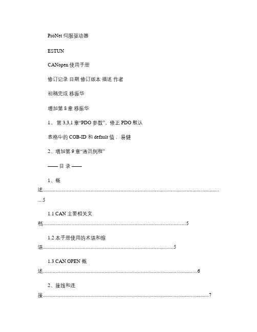
ProNet 伺服驱动器ESTUNCANopen 使用手册修订记录日期修订版本描述作者初稿完成移振华增加第8章移振华1、第3,3,1章“PDO 参数”,修正PDO 默认表格中的COB-ID 和default 值;易健2、增加第9章“通讯例程”——目录——1、概述............................................................................................................................................ . (5)1.1 CAN 主要相关文档 (5)1.2 本手册使用的术语和缩语 (5)1.3 CAN OPEN 概述 (6)2、接线和连接 (7)3、CANOPEN 通讯 (8)3.1 CAN 标识符分配表 (9)3.2 服务数据对象SDO (10)3.3 过程数据对象PDO (12)3.3.1 PDO参数 (14)3.4 SYNC 报文 (20)3.5 E MERGENCY 报文 (21)3.6 HEARTBEAT 报文 (23)3.7网络管理(NMT ) (24)4、单位换算单元(FACTOR GROUP) (26)4.1 单位换算相关参数 (27)4.1.1 position factor (27)4.1.2 velocity factor (29)4.1.3 acceleration factor (30)5、位置控制功能 (31)5.1 位置控制相关参数 (33)6、设备控制 (35)6.1 控制状态机 (35)6.2 设备控制相关参数 (36)6.2.1 controlword (37)6.2.2 statusword (38)6.2.3shutdown_option_code (3)96.2.4disable_operation_option_code (40)6.2.5quick_stop_option_code (4)6.2.6halt_option_code (41)6.2.7fault_reaction_option_code (41)7、控制模式 (42)7.1 控制模式相关参数 (42)7.1.1modes_of_operation (42)7.1.2modes_of_operation_display (43)7.2 回零模式(HOMINGMODE ) (44)7.2.1 回零模式的控制字 (44)7.2.2 回零模式的状态字 (44)7.2.3 回零模式相关参数 (45)7.2.4 回零方法 (47)7.3 速度控制模式(PROFILE VELOCITYMODE ) (49)7.3.1速度模式的控制字 (49)7.3.2 速度模式的状态字 (49)7.3.3 速度控制模式相关参数 (49)7.4 位置控制模式(PROFILE POSITIONMODE ) (53)7.4.1 位置模式的控制字 (53)7.4.2 位置模式的状态字 (53)7.4.3 位置控制相关参数 (54)7.4.4 功能描述 (56)8、CAN 通讯相关参数 (58)9、CANOPEN 通讯例程 (59)9.1 SDO 操作; (59)9.2 PDO 配置 (59)9.3 位置控制例子(P ROFILE P OSITON MODE ) (60)9.4 位置插补控制(I NTERPLATE P OSITION MODE ) (61)9.5 速度控制(P ROFILE V ELOCITY MODE ) (62)9.6 回零 (6)2对象字典表 (64)1、概述1.1 CAN 主要相关文档 CiA DS 301 V 4.01: CiA CANopen Communication Profilefor Industrial Systems - based on CALCiA DSP 402 V 2.0: CiA CANopen Device Profile1.2 本手册使用的术语和缩语CANCiACOBEDSLMTNMTOD参数PDORORWSDO控制器局域网在自动化国际用户和制造商协会中的 CAN。
日鼎DHE系列伺服CANOpen通讯说明书

0001b 0011b 0100b 0101b 0110b 0111b 1000b
1-127 1-127 1-127 1-127 1-127 1-127 1-127
80h+Node-ID 180h+Node-ID 200h+Node-ID 280h+Node-ID 300h+Node-ID 380h+Node-ID 400h+Node-ID
过程数据对象(PDO)
PDO 对象用来传输一些实时数据,例如伺服运行过程中的实时速度或者实时位置。PDO 消 息的内容是预定义的,该预定义的内容由 PDO 的映射参数决定。它是基于生产者/消费者模 型的通信对象,因为 PDO 消息不需要应答而且消息的内容是预定义的,不需要通过索引和 自索引对对象字典进行查找,所以 PDO 效率比 SDO 的通信效率高,适合用来传输实时数据。
有效。
停止状态
当收到 NMT 停止节点命令后,设备进入停止状态,在此状态下,SDO 和 PDO 均无效,只有 NMT 报文可以
正常工作。
不同状态下支持的 CANOpen 通信对象如表 3-8 所示。
表 3-8 不同 NMT 状态下支持的 CANOpen 通信对象
通信对象
预操作状态
操作状态
停止状态
NMT
3.1 对象字典
图 3-1 CANOpen 设备模型
CANOpen 的核心概念是设备对象字典(OD:Object Dictionary),它是一组参数和变量的有序集合。CANOpen
通讯通过对象字典够访问驱动器的所有参数。对象字典中的每个变量称之为对象,每个对象采用一个 16 位
的索引值来寻址,为了允许访问数据结构中的单个元素, 同时定义了一个 8 位的子索引,所以 CANOpen
CANopen产品用户手册

电路板上的电解电容器焚烧时可能会发生爆炸。 可编程控制器主体为塑料件,焚烧时可能会产生有毒气体。 请按工业废弃物进行处理或者按当地环境保护规定处理。
II
CTSC-200 CANopen 系列产品用户手册
前 言
非常感谢您购买和使用深圳市合信自动化技术有限公司(CO-TRUST)的 CANopen 系列产品。为了更清楚地掌握产品的特性,更安全地应用,更充分的利用本产品的丰富功 能,请在使用我公司的 CANopen 系列产品前,敬请您仔细阅读本手册。 本手册主要描述 CTSC-200 CANopen 系列 CPU、扩展模块以及通信接口转换模块的 硬件规格、特性及安装使用方法。 本手册适用于 CTSC-200 CANopen 系列产品应用的学习、设计、安装、运行维护的技 术工程人员。
请不要在通电时触摸端子,以免引起电击、误操作等。 请务必在关闭电源后方可进行清扫和端子的扭紧等工作,在通电状态时这些操作可能 会引起触电。 请务必在关闭电源后才能进行通讯信号电缆的连接或拆除、扩展模块或控制单元的电 缆连接或拆除等操作,否则会引起设备损坏、误操作等。 请不要拆解控制器,以免损坏内部元器件。 请务必仔细阅读熟悉本手册,充分确认安全后,再进行程序的变更、试运行、启动和 停止等操作。 产品报废时的注意事项
参考文献
《CANopen:high-level protocol for CAN-bus》来自荷兰 NIKHEF 公司网站,作者: H. Boterenbrood。
III
CTSC-200 CANopen 系列产品用户手册
安全注意事项.......................................................................................................................................................... I 使用中的注意事项.............................................................................................................................................. I 安装时的注意事项.............................................................................................................................................. I 布线时的注意事项............................................................................................................................................. II 运行和保养时的注意事项..................................................................................................................................II 产品报废时的注意事项..................................................................................................................................... II 系列产品概述.................................................................................................................. 1 1 CTSC-200 CANOPEN CANOPEN系列产品概述 1.1 产品介绍.................................................................................................................................................... 1 1.2 网络架构.................................................................................................................................................... 2 系列产品规格.................................................................................................................. 4 2 CTSC-200 CANOPEN CANOPEN系列产品规格 2.1 性能参数.................................................................................................................................................... 4 2.2 主站之间的通信......................................................................................................................................... 8 2.3 安装............................................................................................................................................................ 9
埃斯顿CANopen使用手册

CAN open使用手册ProNet伺服驱动器ESTUN修订记录日期修订版本描述作者2009/4/25 1.00 初稿完成移振华2009/9/22 1.00 增加第8章移振华—— 目录 ——1、概述 (5)1.1 CAN 主要相关文档 (5)1.2 本手册使用的术语和缩语 (5)1.3 CANopen概述 (6)2、接线和连接 (7)3、CANopen通讯 (8)3.1 CAN标识符分配表 (9)3.2 服务数据对象SDO (10)3.3 过程数据对象PDO (12)3.3.1 PDO参数 (14)3.4 SYNC报文 (20)3.5 Emergency报文 (21)3.6 HEARTBEAT报文 (23)3.7网络管理(NMT) (24)4、单位换算单元(Factor Group) (26)4.1 单位换算相关参数 (27)4.1.1 position factor (27)4.1.2 velocity factor (29)4.1.3 acceleration factor (30)5、位置控制功能 (31)5.1 位置控制相关参数 (33)6、设备控制 (35)6.1 控制状态机 (35)6.2 设备控制相关参数 (36)6.2.1 controlword (37)6.2.2 statusword (38)6.2.3 shutdown_option_code (39)6.2.4 disable_operation_option_code (40)6.2.5 quick_stop_option_code (40)6.2.6 halt_option_code (41)6.2.7 fault_reaction_option_code (41)7、控制模式 (42)7.1 控制模式相关参数 (42)7.1.1 modes_of_operation (42)7.1.2 modes_of_operation_display (43)7.2 回零模式(HOMING MODE) (44)7.2.1 回零模式的控制字 (44)7.2.2 回零模式的状态字 (44)7.2.3 回零模式相关参数 (45)7.2.4 回零方法 (47)7.3 速度控制模式(PROFILE VELOCITY MODE) (49)7.3.1速度模式的控制字 (49)7.3.2 速度模式的状态字 (49)7.3.3 速度控制模式相关参数 (49)7.4 位置控制模式(PROFILE POSITION MODE) (53)7.4.1 位置模式的控制字 (53)7.4.2 位置模式的状态字 (53)7.4.3 位置控制相关参数 (54)7.4.4 功能描述 (56)8、CAN通讯相关参数 (58)附录对象字典表 (59)1、概述1.1 CAN 主要相关文档Document Name Source 3014.01: CiAVDSCiACANopen Communication Profilefor Industrial Systems - based on CALCiA DSP 402 V 2.0: CiACANopen Device Profile1.2 本手册使用的术语和缩语CAN控制器局域网CiA在自动化国际用户和制造商协会中的 CAN。
ELCO CANOPEN编码器使用说明书

1、CANopen介绍 (1)2、通信对象 (2)3、CANopen预定义连接集 (3)4、编码器 (5)4.1 编码器说明 (5)4.2 接线说明 (5)4.3 指拨开关说明 (5)4.3.1 节点地址设定 (6)4.3.2 CAN波特率设定 (6)4.3.3匹配电阻设定 (6)4.3.4旋转方向选择 (7)5、Object directory(对象字典) (8)5.1 Detailed description of the communication parameters(通讯子协议区域) (8)5.1.1 Object 1000H: Device type(设备类型) (8)5.1.2 Object 1001H: Error register(错误寄存器) (8)5.1.3 Object 1003H: Predefined error field(预定义错误区域) (8)5.1.4 Object 1005H: COB-ID for SYNC(SYNC标志符) (9)5.1.5 Object 1008H: Manufacturer device name(制造商设备名) (9)5.1.6 Object 1009H: Hardware version(硬件版本) (9)5.1.7 Object 100AH: Software version(软件版本) (9)5.1.8 Object 100CH und 100DH: Guard Time and life time factor(节点保护参数) (9)5.1.9 Object 1010H: Save parameters(保存参数) (10)5.1.10 Object 1011H: restore default parameters(恢复默认参数值) (10)5.1.11 Object 1014H: COB-ID emergency messages(EMCY标志符) (10)5.1.12 Object 1017H: Producer Heartbeat Time(Heartbeat报文周期) (11)5.1.13 Object 1018H: Identity Object(设备ID) (11)5.1.14 Object 1800H: 1.transmit PDO parameter (TXPDO1 异步) (11)5.1.15 Object 1801H: 2.transmit PDO parameter (TXPDO2 同步) (11)5.2 Detailed Description of the Manufacturer(制造商特定子协议区域) (12)5.2.1 Object 2005H: ELCOBits(编码器位数) (12)5.2.2 Object 2006H: SetPosition(硬件置位值) (12)5.2.3 Object 2007H: CLRSelect(置位方式选择) (12)5.2.4 Object 2008H: DIRSelect(方向选择功能选择) (13)5.3 Detailed Description of the General Encoder Parameters(标准的设备子协议区域) (13)5.3.1 Object 6000H: Operating parameters(操作参数) (13)5.3.2 Object 6001H: Mearsuring unit per revolution(每分辨率对应的单位) (13)5.3.3 Object 6002H: Total mearsuring range in mearsuring units(测量单位内的总测量范围) (13)5.3.4 Object 6003H: Preset value(预置值) (14)5.3.5 Object 6004H: Position value (编码器当前位置值) (14)5.3.6 Object 6200H: Cyclic timer(发送测量值间隔时间) (14)5.3.7 Object 6500H: Operating status(操作状态) (14)5.3.8 Object 6501H: SingleTurn resolution(每圈对应的测量值) (14)5.3.9 Object 6507H: Profile and software version(外形和软件版本) (15)5.3.10 Object 6509H: Offset value(偏移值) (15)5.3.11 Object 650BH: Serial number(出厂序号) (15)7、Layer-Setting-Service (LSS) (16)8、注意事项 (18)9、故障排除 (19)附:CANopen报文分析 (20)1、CANopen介绍从OSI网络模型的角度来看同,现场总线网络一般只实现了第1层(物理层)、第2层(数据链路层)、第7层(应用层)。
台达CANopen及A 伺服简易手册

台达产品简易操作手册(一)台达A2伺服马达接头及对应线序(二)台达A2伺服编码器对应接口视图及线序(三)台达A2伺服PR模式参数设定及对应关系表模式设定P1‐01=1DI1=101伺服使能DI2=108相应PR触发DI3=111(POS0)DI4=112(POS1)DI5=113(POS2)DI6=11A(POS3)DI7=11B(POS4)DI8=11C(POS5)一点说明:(1) 当选定一个PR需要运行时,请首先选择,然后在一点延时触发,这样保证能够运行起来,因为触发是脉冲沿有效。
(2) 当需要行走的距离很长时,PR设定的脉冲无法满足要求是,请设定电子齿轮比,相关参数为P1‐44,P1‐45,电子齿轮比是全局参数,一旦设定所有的PR都按照这个比例行走。
(四)CANopen组态介绍1.首先需要安装台达相应的组态软件CANopen Builder,图标如下图2.安装完成如下图3.开始组态步骤一,如下图一图一4.操作如下:请双击右侧窗口的相应的伺服图片,出现如下窗口。
图二4.开始组态步骤三,配置PDO ,如下图三操作如下:窗口1(如下图)的C 部分,打开时可能有默认数据,如有则没有关系可以把它删除掉,然后根据实际需要进行重新配置。
PDO 里面的Rceive PDO Comm…表示伺服接收的内容,即上位机发送给伺服。
PDO 里面的Transmit PDO Comm…表示伺服发出的内容,即上位机从伺服接收。
双击此图标图三5.开始组态步骤四,配置PDO ,如下图四‐1,图四‐2 操作如下:(1)双击窗口1里面的C 部分的一个参数,出现窗口 图四‐1,如下图四‐1在“参数群”部分选择需要的参数,这里必须需要选择P4‐07,利用“下移”按钮进行选择,也可利用“上移”按钮进行移除。
完毕之后确定即可。
(2)双击窗口1里面的C 部分的另外一个参数,同样出现窗口 图四‐2,如下图四‐2 在“参数群”部分选择需要的参数,这里根据需要可以选择P0‐01(伺服报警),利用“下移”按钮进行选择,也可利用“上移”按钮进行移除。
CANopen旋转编码器使用说明书----上海德晶
CANopen旋转编码器使用说明书----上海德晶内容提要1.注意事项2.标识3.安装4.电气连接5.CANopen 接口6.参数设置7.附件1 注意事项电气安装时应注意以下几个方面:-编码器尽可能地靠近控制单元安装。
-尽可能的使用有屏蔽的双绞线。
-避免信号线靠近高压电缆(例如驱动电缆等)。
-如果需要可以对编码器电源安装EMC 滤波器。
-避免编码器安装在容性性噪声源或开关电源附近。
连接请参考第4 章: "电气连接"。
2 标识设备信息可以通过产品标签上的型号,产品序列号获知。
3 安装。
4 电气连接4.1 CANopen 接线定义连。
4.2 总线终端当编码器为CAN 网络上的最后一个设备时,需要将终端电阻Rt 拨码开关 拨到“ON ”状态。
或感安装时请确保编码器的防护等级符合要求。
避免敲打、撞击、腐蚀编码器4.3 波特率设置:DIP A波特率既可以通过硬件模式设置,也可以通过软件模式设置。
如果DIP A 第4位=OFF 则比特率由对象字典的3000h 来定义,可以通过SDO 报 文进行修改。
如果DIP A 第4 位=ON ,则比特率可由拨码开关 DIP A 进行设置。
由拨码开关设置波特率时,请先关闭掉设备。
波特率可由拨码开关的二进 制状态进行表示(ON 代表1,OFF 代表0)。
拨码开关与波特率对照表例如:设置波特率为250 Kbit/s ,查表可知拨码开关的编码为100,第4位设为ON 。
设置波特率为500 Kbit/s ,查表可知拨码开关的编码为101,第4位设为ON 。
位202122ON/OFF1234位12342012ON FF22/O FF O ONON1234位20122 2ONFFO ONONFF O4.4 节点号设置拨码开关:DIP B编码器的节点号,既可以通过硬件模式设置,也可以由软件模式进行设置,范围 1 至127 之间节点号由数据01h 文进行修改。
如果DIP B 则节点号由DIP B 来定义。
Baumer EAM580_360 CANopen Lift 协议绝对编码器手册说明书
ManualAbsolute encoder with CANopen Lift-Protocol DS-417 Baumer Electric AGHummelstrasse 17CH-8501 FrauenfeldPhone +41 52 728 11 22Fax +41 52 728 11 44 01.18Contents1Version overview (4)2Safety and operating instructions (5)3Product Assignment (6)3.1Absolute encoder (6)4System Overview (7)4.1General (7)4.2Supported Profiles (7)4.3Supported CANopen Services (7)4.4Function Principle (7)4.4.1Overview (7)4.4.2Scaling (8)4.4.3Position Range (9)4.4.4Speed range (9)4.5Encoder as standard component with embedded software used in safety functions (9)5NMT Service (10)5.1Supported commands (10)5.1.1NMT Reset (10)5.1.2NMT Communication Reset (10)5.2Boot-up message (10)6SDO service (11)6.1General (11)6.2Save/load parameters (11)6.2.1Save (11)6.2.2Load (11)6.2.3Safe non-volatile operation (11)7PDO Service (12)7.1General (12)7.2PDO transmission types (12)7.3COB-ID (12)7.4PDO mapping (12)7.4.1Mappable objects (12)7.4.2Default mapping of absolute encoder (13)7.5Timing (13)7.6Exceptions of accurate calculation of process data (13)8Emergency Service (14)8.1General (14)8.2COB-ID (14)8.3Emergency message (14)8.4Error register (14)8.4.1Communication error (14)8.4.2Temperature error (14)8.4.3Generic error (14)8.5Error codes (15)9Alarms, warnings, errors, emergency messages and error behavior (16)9.1Absolute encoder (16)9.2Error behavior (17)9.30x2117 16-Bit Encoder Diagnostics (17)10Heartbeat Service (19)10.1General (19)10.2COB-ID (19)10.3Timing (19)11LSS slave (20)11.1General (20)11.2Supported commands (20)11.3LSS address (20)12Object directory (21)12.1Communication Profile Area (21)12.2Manufacturer Specific Profile Area (22)12.3Standardized Device Profile Area (23)13Applications (24)14Discrepancies to the CIA specifications (25)A.Appendix (26)a.Pin Assignments (26)1 Version overviewThis document is subject to changes. In order to have the most current version please download on 2 Safety and operating instructionsIntended use∙The encoder is a precision measuring device that is used to record positions and speeds. It provides measuring values as electronic output signals for the subsequently connected device. It must not be used for any otherpurpose. Unless this product is specially labeled, it may not be used for operation in potentially explosiveenvironments.∙Make sure by appropriate safety measures, that in case of error or failure of the encoder, no danger to persons or damage to the system or operating facilities occurs.Personnel qualification∙Installation and assembly of this product may be performed only by a person qualified in electronics and precision mechanics.Maintenance∙The encoder is maintenance-free and must not be opened up nor mechanically or electronically modified. Opening up the encoder can lead to injury.Disposal∙The encoder contains electronic components. At its disposal, local environmental guidelines must be followed. Mounting∙Solid shaft: Do not connect encoder shaft and drive shaft rigidly. Connect drive and encoder shaft with a suitable coupling.∙Hollow shaft: Open clamping ring completely before mounting the encoder. Foreign objects must be kept at a sufficient distance from the stator coupling. The stator coupling is not allowed to have any contact to the encoder or the machine except at the mounting points.Electrical commissioning∙Do not proceed any electrical modifications at the encoder.∙Do not proceed any wiring work while encoder is live.∙Do not remove or plug on connector whilst under power supply.∙Ensure that the entire system is installed in line with EMC/EMI requirements. Operating environment and wiring have an impact on the electromagnetic compatibility of the encoder. Install encoder and supply cables separately or far away from sources with high emitted interference (frequency converters, contactors, etc.).∙When working with consumers with high emitted interference provide separate encoder supply voltage.∙Completely shield encoder housing and connecting cables.∙Connect encoder to protective earth (PE) using shielded cables. The braided shield must be connected to the cable gland or connector. Ideally, aim at dual connection to protective earth (PE), i.e. housing by mechanical assembly and cable shield by the downstream devices.Supplementary information∙The present manual is intended as a supplement to already existing documentation (e.g. catalogues, data sheets or mounting instructions).3 Product Assignment 3.1 Absolute encoder4 System Overview4.1 GeneralThe encoder is a rotary measuring system with a CANopen interface. It supports scaling and presetting.4.2 Supported ProfilesFollowing CANopen profiles are supported:∙CiA 301 / Version 4.1 (Communication)∙CiA 305 / Version 1.0 (LSS)∙CiA 417 / Version 2.0 (Encoder Profile)4.3 Supported CANopen ServicesFollowing CANopen services are supported:∙ 1 Network Management (according to CiA 301)∙ 1 SDO Server (according to CiA 301)∙ 2 TPDOs (according to CiA 301/CiA 417)∙ 1 Emergency Producer (according to CiA 301)∙ 1 Heartbeat Producer (according to CiA 301)∙ 1 Node guarding (according to CiA 301)∙ 1 LSS Client (according to CiA 305)4.4 Function Principle4.4.1 OverviewFigure 1: Function principle overview4.4.2 ScalingThe scaling of the position object can be adapted in the object 6381h and 6384-1h. Speed object can be adapted in the object 6384-2h.Example for unit settings:1. Setting measuring units per revolution (6381-1h)a. To set the measuring units per revolution, the resulting measuring step should be considered. Themeasuring step (6384-1h), has a granularity of 10 µm.b. The circumference of the bobbin is U=2∗π∗r=2∗π∗100′000 µm=628318.531 µmc. For the example above, the measuring units per revolution should be set to((6381−1ℎ)=U10 µm =628318.531 µm10 µm=62831.85, because the object 6381-1h only supports 14-BitResolution, the highest possible units per revolution is set -> (6381−1ℎ)=62831.855=12566, whichwill result in a position measuring step value of U6381−1ℎ=628318.531 µm12566=50.0015 µm2. Setting position measure step setting (6384-1h)a. Measuring step setting is (6384−1ℎ)=U6381−1ℎ∗ 10 µm =628318.53112566∗ 10 µm=53. Speed measure step setting (6384-2h)a. To get the user-unit in [cm/s] the object (6384−2ℎ)=Unit_User0.1 mm/s =1[cms]0.1[mms]=104.4.3 Position RangeThe range of the position is depending on the position step setting (object 6381h) and number of distinguishable revolutions (object 63C2h).4.4.4 Speed range0x6390This object provides a 16-Bit Speed information, which has the user-unit, according to 6384-2h (default = [1 cm/s]). The range for object 6390h-1 Speed encoder A is -8000h…7FFF’h.If the scaled speed value exceeds this range, the output is -8000h or 7FFFh (Saturated Logic). Figure 2: Speed ranget p u t4.5 Encoder as standard component with embedded software used in safety functionsIf this standard encoder is used in safety functions, please request the according “Application Note MAGRES EAM” for further information.5 NMT Service5.1 Supported commandsFollowing NMT commands are supported:5.1.1 NMT ResetThis NMT command performs a complete reset of the encoder, which can take up to 170 ms until the new bootup-message is sent (restarting of the micro controller, be aware that all unsaved configurations will be lost).5.1.2 NMT Communication ResetThis NMT command performs a restarting of the CAN Controller, which can take up to 5 ms until the new bootup-message is sent (be aware that all unsaved configurations will be lost). When NMT communication reset is performed, emergency messages (0x6503, 0x6505, 0x1001) are not send again automatically.5.2 Boot-up messageAfter a power-on or NMT reset, the device will send a Boot-up message.6 SDO service6.1 GeneralThe device supports 1 SDO server (Expedited read/write, segmented read)6.2 Save/load parametersThe device supports saving parameters to a non-volatile memory.6.2.1 SaveWriting “save” to 1010h-x saves the corresponding objects to the non-volatile memory. After a reset or power-on, the parameters are loaded from the non-volatile memory.The SDO request to 1010h-x is answered after the saving of the parameters is performed.6.2.2 LoadWriting “load” to 1011h-x restores the corresponding objects. The parameters are restored after a reset or power-on.6.2.3 Safe non-volatile operationTo ensure safe non-volatile operation, the user must ensure no power interruption immediately after sending of the save command to object 1010h-x (otherwise, the factory values are restored at the next power up).7 PDO Service7.1 GeneralThe device supports TPDO263 and TPDO264. PDOs are only transmitted in NMT operational mode.7.2 PDO transmission typesThe following transmission types are supported (object 180xh-2):∙Synchronous transmission (1-240)∙Asynchronous transmission (255)∙Manufacturer transmission (254)∙RTR-only transmission, event-driven (253)Both PDO support all transmission types.Transmission type 253: The PDO is only transmitted on request (remote transmission request). Transmission type 255 and 254: The PDO is transmitted timer driven. The time interval between 2 PDOs can beadapted in the object 180xh-5Transmission type 1-240: The PDO is transmitted after the n-th sync frame.Transmission type 1: The PDO is transmitted after one sync frame.Transmission type 2: The PDO is transmitted after two sync frames.etc.As default, Transmission type 255 is set for the PDO.7.3 COB-IDThe COB-ID for both PDO are not changeable.Default Values are:TPDO263: 18ChTPDO264: 18DhChanges will be applied immediately.7.4 PDO mappingThe encoder supports dynamic mapping.7.4.1 Mappable objectsThe following objects are mappable:To change PDO mapping, disabling the mapping by writing 0 to 0x1A0x-0 is required first. Write the desired mapping entry and enable the mapping again by writing the number of PDO contents to 0x1A0x-0.7.4.2 Default mapping of absolute encoderThe mappings for both PDOs are the same. The position will be transmitted in byte 0...3.Byte 0...3: Position value (Object 6383-1h)Byte 4...5: Speed value (Object 6390-1h)PDO264 is disabled by default, because a second sensor is not built in.7.5 TimingThe minimal cycle time for TPDOs is 1 ms, the default time is set to 0.7.6 Exceptions of accurate calculation of process dataThe following operations could interrupt the accurate calculation of process data such as position, speed, warnings and alarms:- Changing the scaling parameters8 Emergency Service8.1 GeneralIf there is an error on the device, the device commits an emergency message and sets the corresponding bits in the error register (Object 1001h).Error codes are accessible by the error field (object 1003h-x). A history of maximal 8 error codes is stored in the error field.8.2 COB-IDThe COB-ID for the emergency message can be modified in object 1014h.Default Value: 80h + node IDChanges will be applied immediately.The COB-ID is stored internally as a difference to the default COB-ID. Example:Node ID: 1 COB-ID Emergency: 81h (Default value)COB-ID Emergency: 87h (Changed by user)Node ID: 3 COB-ID Emergency: 89h (Adapted automatic)8.3 Emergency messageThe format of the emergency messages is according to CiA 301. Additionally, the encoder sends the warning and alarm fields (object 6503h, 6505h).The emergency message is transmitted if an error is indicated in the error register.8.4 Error register8.4.1 Communication errorCommunication errors are indicated if the internal CAN message buffers are overflowed or there are malformed CAN frames on the bus. After a communication error the corresponding operation (described in object 1029h-1) is executed.8.4.2 Temperature errorThis error is indicated, when the internal temperature of the encoder is above a certain threshold level, at which the position can’t be guaran teed.8.4.3 Generic errorA generic error is indicated for all other errors.An encoder specific alarm or warning will also cause a generic error.After a generic error the corresponding operation (described in object 1029h-2) is executed.8.5 Error codesThe following error codes are generated by the device:9 Alarms, warnings, errors, emergency messages and error behaviorFigure 6 show the surveillance mechanisms. If one of them fails, an alarm or warning will be indicated. The behavior upon an error can be defined and is described in chapter 8.3.9.1 Absolute encoderFigure 4: Dataflow of Error, Alarm, Warning and Emergency messages1029h-2h1029h-1h 1029h-3h1029h-1h9.2 Error behaviorThe error behaviors are executed when the corresponding bit in object 1001 Error register is set and the device is in the NMT-State Operational.Example:The error behavior 1029h-2 is set to “Change to Pre-Operational” (0). The device is in NMT state Operational1. Generic error bit is set.→ The device changes to Pre-Operational2. The device is forced to NMT state Operational with NMT command Start→ The device changes again to Pre-Operational if the generic error bit is not cleared.9.3 0x2117 16-Bit Encoder DiagnosticsIn order to get more different objects in one PDO message, the Objects Error (0x1001), Alarm (0x6503) and Warning (0x6505) have been summarized in 2 Bytes.Byte 0: WarningsByte 1: Errors10 Heartbeat Service10.1 GeneralThe device supports a heartbeat producer according CiA 301.10.2 COB-IDThe COB-ID for the heartbeat message is 700h + node ID.10.3 TimingThe minimal cycle time for heartbeat messages is 1 ms, which can be configured with object 1017h-011 LSS slave11.1 GeneralThe baudrate and node ID can be configured by LSS (according to CiA 305). Another possibility to change the baudrate and node ID is to access to the objects 2100h and 2101h (see object directory).The LSS service is only available in NMT Stopped Mode.11.2 Supported commands▪Switch state global▪Switch state selective▪Configure node ID protocol▪Configure bit timing parameters▪Store configuration▪Inquire identity vendor-ID▪Inquire identity product code▪Inquire identity revision number▪Inquire identity serial number▪Inquire identity node ID11.3 LSS addressThe needed values for LSS addressing as vendor ID, revision number, product code and serial number are printed on a label on the encoder housing.12 Object directoryThe following tables provide a summary of all SDO objects supported by the encoder.Object Object number in HexName Object nameFormat U/I = Unsigned/Integer, No. = no of bits, ARR = Array, REC = Record, STR = String Access ro = read only, wo = write only, rw = read write, m = mappableDefault Default value on first initSave X = can be stored in the EEPROMDescription Additional information12.1 Communication Profile Area12.2 Manufacturer Specific Profile Area12.3 Standardized Device Profile Area13 ApplicationsChanging the node ID and baud rate with LSSThe node ID and baud rate can be changed without having to use these to address the encoder. With the LSS service, the sensors are addressed and configured via the product code, revision no., vendor ID and serial number.Changing the node ID (node no.)The node ID can be changed in object 2101h between 1 and 127. A save routine should then be executed using object 1010h. On the next initialization, the encoder logs on with the new node ID.Changing the baud rateThe baud rate can be changed in the object 2100h. An index is written into the object, not the effective baud rate.The baud rate now still has to be saved using object 1010-1. On next initialization, the encoder logs on to the new baud rate. However, before this the baud rate of the master should be changed.14 Discrepancies to the CIA specificationsA. Appendixa. Pin AssignmentsAssignment cable (connection – L)Pin assignment connector 1 x M12 (connection – N)。
20110708Canopen使用手册说明
目录第一章概述------------------------------------------------3第二章PC10卡--------------------------------------------4第三章E3000-CANopen接口---------------------------73.1 CANopen信息框---------------------------------73.2 对象字典描述---------------------------------------73.3 制造商特定参数详细说明------------------------103.4 状态机操作------------------------------------------153.5 默认PDO配置--------------------------------------183.6CANopen通讯使用的相关配置参数---------20 第四章电子数据文档—EDS文件----------------------23 第五章故障描述和处理-----------------------------------24第一章概述CANopen 是基于串行总线控制器局域网(CAN)的网络系统。
CANopen 通讯行规(CiA DS-301)支持直接访问装置参数及时间关键型进程数据通讯。
CANopen 装置行规(CiA DS-402)定义了基本装置功能性的标准,而这些基本装置提供了附加供应商特定装置的多种特点。
CANopen通过以组织好的,如果必要可用确定好的方式允许节点间等对等数据交换来产生CAN的最大效能。
通过对网络启动与错误管理提供标准机理,CANopen 特定网络管理功能将方案设计、实施和诊断进行了简单化。
CANopen既支持双循环通讯也支持事件驱动型通讯,从而使将总线负载降到最低,但仍保持极短的反应时间。
CANOpen编码器说明书(DOC)
1、CANopen介绍 (1)2、通信对象 (1)3、CANopen预定义连接集 (3)4、编码器 (5)4.1 编码器说明 (5)4.2 接线说明 (5)5、Object directory(对象字典) (7)5.1 Detailed description of the communication parameters(通讯子协议区域) (7)5.1.1 Object 1000h: Device type(设备类型) (7)5.1.2 Object 1001h: Error register(错误寄存器) (7)5.1.3 Object 1003h: Predefined error field(预定义错误区域) (7)5.1.4 Object 1005h: COB-ID for SYNC(SYNC标志符) (8)5.1.5 Object 1008h: Manufacturer device name(制造商设备名) (8)5.1.6 Object 1009h: Hardware version(硬件版本) (8)5.1.7 Object 100Ah: Software version(软件版本) (8)5.1.8 Object 100Ch und 100Dh: Guard Time and life time factor(节点保护参数) (8)5.1.9 Object 1010h: Save parameters(保存参数) (9)5.1.10 Object 1011h: restore default parameters(恢复默认参数值) (9)5.1.11 Object 1014h: COB-ID emergency messages(EMCY标志符) (9)5.1.12 Object 1017h: Producer Heartbeat Time(Heartbeat报文周期) (10)5.1.13 Object 1018h: Identity Object(设备ID) (10)5.1.14 Object 1800h: 1.transmit PDO parameter (TXPDO1 异步) (10)5.1.15 Object 1801h: 2.transmit PDO parameter (TXPDO2 同步) (10)5.2 Detailed Description of the Manufacturer(制造商特定子协议区域) (11)5.2.1 Object 2000h: Mode(工作模式) (11)5.2.2 Object 2001h: LocalAddress(编码器通讯地址) (12)5.2.3 Object 2002h: Max_LoopValue(循环测量时的最大值) (12)5.2.4 Object 2003h: Min_BackForthValue(往复测量时的最小值) (12)5.2.5 Object 2004h: Max_BackForthValue(往复测量时的最大值) (12)5.3 Detailed Description of the General Encoder Parameters(标准的设备子协议区域) (13)5.3.1 Object 6000h: Operating parameters(操作参数) (13)5.3.2 Object 6003h: Preset value(外部置位的设定值) (13)5.3.3 Object 6004h: Value of position(编码器当前位置值) (14)5.2.6 Object 6200h: Cyclic timer(发送测量值间隔时间) (14)5.3.4 Object 6500h: Operating status(操作状态) (14)5.3.5 Object 6501h: SingleTurn resolution(每圈对应的测量值) (14)5.3.6 Object 650Bh: Serial number(出厂序号) (14)6、RS232通讯参数 (15)7、Layer-Setting-Service (LSS) (16)附:CANopen报文分析 (18)1、CANopen介绍从OSI网络模型的角度来看同,现场总线网络一般只实现了第1层(物理层)、第2层(数据链路层)、第7层(应用层)。