基于MATLAB的结晶器液位模糊控制器的设计与仿真
结晶器液位模糊控制系统的优化设计与仿真
结晶器液位模糊控制系统的优化设计 与仿真
李 明伟 。 等
结 晶器液位模 糊控制系统 的优化 设计与仿 真
Op i u De i n a d Si ua in o u z o d L v l tm m sg n m lt f F z y M l e e o Con r l y t m to s e S
程, 最后利用 M T A A L B软件进行 了仿真实验 。结果表 明 , 优化模 糊控制的 引入有效 地克服 了系统的扰 动 , 提高 了系统 的控 制性 能 。
关键词调整
仿真
中图分 类号 :TE 3 I7
文献 标志 码 :A
Ab ta t T e p o e so l e e o to e o s v r o l ae e a s ft e n n ie rc aa trsiso i a iga d lg To a sr c : h rc s fmod lv lc nrlb c me ey c mpi td b c u e o h o ln a h r ceit ft c c me v r n n a . — y g is h r be xsig i ec n e to a D o t la d fzyc nr l n o t m u z o to c e sp e e td t mp v h o an ttep o lmse it n t o v n in lPI c nr n u z o to ,a pi n h o mu fzyc nr l h mei r s ne o i r et ec n— s o
液位 传 感器
是实现连铸设 备 自动化 的关键环 节 , 它对 保证 连铸机
的安全 、 可靠运行 , 善铸坯 的质 量 , 改 提高 铸机 的生产 率以及改善操作条件等都是一个很重要 的环节 。
基于Matlab的模糊控制系统的设计与仿真

编辑该系统得到仿真框如图 A 所示。对图 A 进行仿真, 需 要用鼠标双击其中的 $4VVK7W9;)?7F98*395563 模块, 打开它, 写 然后选择 &)L45)8M中的 &*@3* , 启 入事先已建好的 $%& 的名字, 动仿真过程, 就可通过 &?9X6 观察系统的仿真输出结果。结果 如图 E 所示。
!" 引言
模 糊 理 论 是 在 美 国 伯 克 莱 加 州 大 学 电 气 工 程 系 #$ % $&
的 任 意 一 个 对 BO= 的 修 改 将 影 响 任 何 其 它 已 打 开 的 NGO 中 的 显示结果。
’()*+ 教 授 于 !,-. 年 创 立 的 模 糊 集 合 理 论 的 数 学 基 础 上 发 展
E2,曲面观察器
规则观察器以非常详细的方式在任意时刻显示 计 算 过 程 , 从这个意义上看, 它给出了模糊推理系统一种微观的 视 角 。 如 果想看系统的整个输出曲面观察器, 即基于整个输入 集 的 输 出 级的变化范围, 需要打开曲面观察器。 看 曲 面 观 察 器 可 以 从 C)6D, 菜 单 选 择 &43.@?6 1 1 1来 打 开 它 , 到表示从 FGH 模糊控制系统映射的三维曲面观察器窗口如图 由这一个双输入、 单输出情况, 可以在图 " 中看到整个 " 所示, 映射。在图的下半部曲面观察器配备了初始菜单, 可以选择用 于绘图的两个输入量 ’ 、 ’F 和一个输出量 I 。弹出式菜单正下 方是两个文本输入域,可以确定在 J 轴和 K 轴包含多少网格 线。这为复杂的问题提供了合理的计算时间。 图 E77系统的仿真输出结果 图 A77系统的仿真框
・ E- ・
基于MATLAB模糊控制器设计和仿真

模块库中的模块到结构图编辑器中,再将它们适当 连接便构成自己的控制系统结构图,然后即可用
simulink进行仿真,并可通过示波器模块(scope) 观察仿真曲线。
为比较被控对象变化时模糊控制器的控制性
能,本文设计的模糊控制系统由三个模糊控制器组
成,被控对象是两个参数不同的二阶对象和一个一 阶对象。这三个模糊控制器的控制规则和比例因子 ke、kec、ku完全相同,并接入了相同的积分环节 以克服静差。
2 基于MATLAB的模糊控制器
的设计和仿真
①采用MAllLAB的模糊逻辑工具箱的GuI (Graph u鸵r Interface)工具设计模糊控制器
工具简介 主要使用模糊逻辑工具箱的五个
GuI工具:FIs(Fizzy Inference system)编辑器、隶 属函数编辑器、规则编辑器、规则观测器和曲面观 测器,它们之间是动态连接的。
.22.
基于mrⅡ,AB模糊控制器设计和仿真
基于MATLAB模糊控制器设计和仿真
李秀娟 天津大学 于 力 天津住宅集团房地产销售有限公司
摘要文中详细介绍用MATLAB6.1设计和仿真模糊控制器的方法,并给出仿真实例。 关键词 模糊控制 仿真MATLAB
Research of F眦zy Contr0Uer DIesi舯and Simulation B嬲ed on MA,Ⅱ。AB
第一部分:介绍国内和国外不稳定体控制的背景,将不稳定体的现有控制方法作以概括和描述,分析其优缺点,并引出自己的动态模糊控制方法。 第二部分:详细介绍模糊控制原理,包括模糊数学基础,模糊控制系统的结构设计,根据传统静态模糊控制器来构造出新的动态模糊控制器,并给 出动态模糊控制器的具体结构以及实现方法。 第三部分:建立“跷跷板”不稳定体系统数学模型,得出描述系统的微分方程。虽然在模糊控制的方法下是不需要知道被控对象的数学模型,但是 为了在计算机上的仿真需要,还是要推导出一个模型来执行仿真过程。对于“跷跷板”这个单输入、多输出的系统,我们选择用状态方程来描述它。 第四部分:详细介绍如何运用Simulink工具实现模糊控制的仿真。在仿真过程中针对传统的静态模糊控制器提出动态模糊控制器这一优化方法,并 用动态模糊控制器来完成“跷跷板”的仿真演示。通过比较两种方法的仿真结果,发现动态模糊控制器的控制效果明显优于传统模糊控制器。
基于MATLAB的模糊控制器的设计及其实现

目录1.毕业实践任务书--------------------------------------------------------------02.外文翻译-----------------------------------------------------------------------13.毕业实践调研报告-----------------------------------------------------------84.毕业设计说明-----------------------------------------------------------------105.毕业实践总结-----------------------------------------------------------------436.参考文献--------------------------------------------------------44毕业实践任务书课题需要完成的任务:课题基于MATLAB进行设计,要求给出simulink仿真结果。
主要设计要求如下:(1)控制对象:二阶系统;(2)系统超调小于10%;(3)稳态误差小于3%;(4)设计相应simulink模块并仿真。
课题计划:2.13-2.19 熟悉课题背景知识,查阅参考资料;2.20-3.4 选择设计方案;3.5 -3.25 应用MATLAB设计相应的simulink模块;3.26-4.1 进行仿真并调试;4.2 -4.8 编写毕业设计论文;准备毕业答辩。
计划答辩时间:年月日日机电技术学院自控系(部、分院)年月日原文:A proportional–integral–derivative controller (PID controller) is a generic .control loop feedback mechanism widely used in industrial control systems. A PID controller attempts to correct the error between a measured process variable and a desired setpoint by calculating and then outputting a corrective action that can adjust the process accordingly.The PID controller calculation (algorithm) involves three separate parameters; the Proportional, the Integral and Derivative values. The Proportional value determines the reaction to the current error, the Integral determines the reaction based on the sum of recent errors and the Derivative determines the reaction to the rate at which the error has been changing. The weightedsum of these three actions is used to adjust the process via a control element such as the position of a control valve or the power supply of a heating element.By "tuning" the three constants in the PID controller algorithm the PID can provide control action designed for specific process requirements. The response of the controller can be described in terms of the responsiveness of the controller to an error, the degree to which the controller overshoots the setpoint and the degree of system oscillation. Note that the use of the PID algorithm for control does not guarantee optimal control of the system or system stability.Some applications may require using only one or two modes to provide the appropriate system control. This is achieved by setting the gain of undesired control outputs to zero. A PID controller will be called a PI, PD, P or I controller in the absence of the respective control actions. PI controllers are particularly common, since derivative action is very sensitive to measurement noise, and the absence of an integral value may prevent the system from reaching its target value due to the control action.Note: Due to the diversity of the field of control theory and application, many naming conventions for the relevant variables are in common use.1.Control loop basicsA familiar example of a control loop is the action taken to keep one's shower water at the ideal temperature, which typically involves the mixing of two process streams, cold and hot water. The person feels the water to estimate its temperature. Based on thismeasurement they perform a control action: use the cold water tap to adjust the process. The person would repeat this input-output control loop, adjusting the hot water flow until the process temperature stabilized at the desired value.Feeling the water temperature is taking a measurement of the process value or process variable (PV). The desired temperature is called the setpoint (SP). The output from the controller and input to the process (the tap position) is called the manipulated variable (MV). The difference between the measurement and the setpoint is the error (e), too hot or too cold and by how much.As a controller, one decides roughly how much to change the tap position (MV) after one determines the temperature (PV), and therefore the error. This first estimate is the equivalent of the proportional action of a PID controller. The integral action of a PID controller can be thought of as gradually adjusting the temperature when it is almost right. Derivative action can be thought of as noticing the water temperature is getting hotter or colder, and how fast, and taking that into account when deciding how to adjust the tap.Making a change that is too large when the error is small is equivalent to a high gain controller and will lead to overshoot. If the controller were to repeatedly make changes that were too large and repeatedly overshoot the target, this control loop would be termed unstable and the output would oscillate around the setpoint in either a constant, growing, or decaying sinusoid. A human would not do this because we are adaptive controllers, learning from the process history, but PID controllers do not have the ability to learn and must be set up correctly. Selecting the correct gains for effective control is known as tuning the controller.If a controller starts from a stable state at zero error (PV = SP), then further changes by the controller will be in response to changes in other measured or unmeasured inputs to the process that impact on the process, and hence on the PV. Variables that impact on the process other than the MV are known as disturbances and generally controllers are used to reject disturbances and/or implement setpoint changes. Changes in feed water temperature constitute a disturbance to the shower process.In theory, a controller can be used to control any process which has a measurable output (PV), a known ideal value for that output (SP) and an input to the process (MV) that will affect the relevant PV. Controllers are used in industry to regulate temperature,pressure, flow rate, chemical composition, speed and practically every other variable for which a measurement exists. Automobile cruise control is an example of a process which utilizes automated control.Due to their long history, simplicity, well grounded theory and simple setup and maintenance requirements, PID controllers are the controllers of choice for many of these applications.While PID controllers are applicable to many control problems, they can perform poorly in some applications.PID controllers, when used alone, can give poor performance when the PID loop gains must be reduced so that the control system does not overshoot, oscillate or "hunt" about the control setpoint value. The control system performance can be improved by combining the feedback (or closed-loop) control of a PID controller with feed-forward (or open-loop) control. Knowledge about the system (such as the desired acceleration and inertia) can be "fed forward" and combined with the PID output to improve the overall system performance. The feed-forward value alone can often provide the major portion of the controller output. The PID controller can then be used primarily to respond to whatever difference or "error" remains between the setpoint (SP) and the actual value of the process variable (PV). Since the feed-forward output is not affected by the process feedback, it can never cause the control system to oscillate, thus improving the system response and stability.For example, in most motion control systems, in order to accelerate a mechanical load under control, more force or torque is required from the prime mover, motor, or actuator. If a velocity loop PID controller is being used to control the speed of the load and command the force or torque being applied by the prime mover, then it is beneficial to take the instantaneous acceleration desired for the load, scale that value appropriately and add it to the output of the PID velocity loop controller. This means that whenever the load is being accelerated or decelerated, a proportional amount of force is commanded from the prime mover regardless of the feedback value. The PID loop in this situation uses the feedback information to effect any increase or decrease of the combined output in order to reduce the remaining difference between the process setpoint and the feedback value. Working together, the combined open-loop feed-forward controller and closed-loop PIDcontroller can provide a more responsive, stable and reliable control system.Another problem faced with PID controllers is that they are linear. Thus, performance of PID controllers in non-linear systems (such as HVAC systems) is variable.Along with the development of Fuzzy Mathematics, control engineers gradually pay much attention to the idea of Fuzzy Control, thus promoting the invention of fuzzy controllers. However, simple fuzzy controller has its own defect, where control effect is quite coarse and the control precision can not reach the expected level. Therefore, the Fuzzy Adaptive PID Controller is created by taking advantage of the superiority of PID Controller and Fuzzy Controller. Taken this controller in use, the corresponding error and its differential error of the control system can be feed backed to the Fuzzy Logic Controller. Moreover, the three parameters of PID Controller is determined online through fuzzification, fuzzy reasoning and defuzzification of the fuzzy system to maintain better working condition than the traditional PID controller.Meanwhile,the design method and general steps are introduced of the Parameter self-setting Fuzzy PID Controller. Eventually, the Fuzzy Inference Systems Toolbox and SIMULINK toolbox are used to simulate Control System. The results of the simulation show that Self-organizing Fuzzy Control System can get a better effect than the Classical PID controlled evidently.Keywords:Classic PID control; Fuzzy Control; Parameters tuning; the Fuzzy Adaptive PID Controller; MA TLAB simulation译文:比例积分微分控制器(PID调节器)是一个控制环,广泛地应用于工业控制系统里的反馈机制。
连铸机结晶器液位控制系统数学模型及其仿真

连铸机结晶器液位控制系统数学模型及其仿真连铸机结晶器液位控制系统是一个复杂的系统,它的性能直接影响到连铸机的生产效率,因此,对连铸机结晶器液位控制系统的研究是非常重要的。
本文首先简要介绍了连铸机结晶器液位控制系统的结构及工作原理,然后探讨了基于结构参数分析的数学模型,最后对模型进行仿真,得出了连铸机结晶器液位控制系统的数学模型及其仿真的结论。
1.连铸机结晶器液位控制系统简介连铸机结晶器液位控制系统是一种多参数控制系统,它是由连铸机结晶器、液位传感器、控制器、调节阀和电动蝶阀组成的(图1)。
图1铸机结晶器液位控制系统连铸机结晶器是一种机械设备,它将液体转化为固体,由于结晶过程的特点,液位变化会影响结晶质量,因此,需要对结晶器的液位进行控制。
液位传感器检测结晶器液位信号,控制器根据液位检测信号进行控制,调节阀和电动蝶阀调节结晶器的液位,从而实现对液位的控制。
2.数学模型为了研究连铸机结晶器液位控制系统,首先分析控制系统结构,建立系统数学模型,根据结构参数推导出如下数学模型:ttttt Vm = Kp*(|S|-S0)tttt(1)其中Kp为控制器参数,S0为液位参考值,|S|为液位测量值,Vm为控制器输出值。
3.仿真针对连铸机结晶器液位控制系统,结合数学模型,使用Matlab/Simulink环境建立了仿真模型,根据实际情况,设置参数如下:Kp=0.5,S0=2,液位变化范围为0~4。
图2铸机结晶器液位控制系统仿真模型根据仿真模型,控制器输出值Vm与液位|S|的变化曲线如图3所示:图3位及控制器输出值的变化曲线从上图可以看到,随着液位|S|的变化,控制器输出值Vm也随之变化,并且同步变化,Vm和|S|的变化幅度接近,这表明,控制器对液位的控制是有效的。
4.结论本文针对连铸机结晶器液位控制系统,根据结构参数推导出了数学模型,并且基于 Matlab/Simulink环境建立了仿真模型,仿真结果显示,控制器输出值Vm能有效地控制液位|S|,表明数学模型具有较强的可靠性和实际应用价值。
基于matlab的模糊控制器的设计与仿真
基于MATLAB的模糊控制器的设计与仿真摘要:本文对模糊控制器进行了主要介绍。
提出了一种模糊控制器的设计与仿真的实现方法,该方法利用MA TLB模糊控制工具箱中模糊控制器的控制规则和隶属度函数,建立模型,并进行模糊控制器设计与仿真。
关键词:模糊控制,隶属度函数,仿真,MA TLAB1 引言模糊控制是一种特别适用于模拟专家对数学模型未知的较复杂系统的控制,是一种对模型要求不高但又有良好控制效果的控制新策略。
与经典控制和现代控制相比,模糊控制器的主要优点是它不需要建立精确的数学模型。
因此,对一些无法建立数学模型或难以建立精确数学模型的被控对象,采用模糊控制方法,往往能获得较满意的控制效果。
模糊控制器的设计比一般的经典控制器如PID控制器要复杂,但如果借助MATLAB则系统动态特性良好并有较高的稳态控制精度,可提高模糊控制器的设计效率。
本文在MATLAB环境下针对某个控制环节对模糊控制系统进行了设计与仿真。
2 模糊控制器简介模糊控制器是一种以模糊集合论,模糊语言变量以及模糊推理为数学基础的新型计算机控制方法。
显然,模糊控制的基础是模糊数学,模糊控制的实现手段是计算机。
本章着重介绍模糊控制的基本思想,模糊控制的基本原理,模糊控制器的基本设计原理和模糊控制系统的性能分析。
随着科学技术的飞速发展,在那些复杂的,多因素影响的严重非线性、不确定性、多变性的大系统中,传统的控制理论和控制方法越来越显示出局限性。
长期以来,人们期望以人类思维的控制方案为基础,创造出一种能反映人类经验的控制过程知识,并可以达到控制目的,能够利用某种形式表现出来。
而且这种形式既能够取代那种精密、反复、有错误倾向的模型建造过程,又能避免精密的估计模型方程中各种方程的过程。
同时还很容易被实现的,简单而灵活的控制方式。
于是模糊控制理论极其技术应运而生。
3 模糊控制的特点模糊控制是以模仿人类人工控制特点而提出的,虽然带有一定的模糊性和主观性,但往往是简单易行,而且是行之有效的。
模糊控制器的设计与MATLAB仿真
模糊控制器的设计与MATLAB仿真模糊控制器的设计与MATLAB仿真王桥( 安庆师范学院物理与电气工程学院安徽安庆246011)指导教师:吴文进摘要:随着现代科学技术的迅速发展,生产系统的规模越来越大,形成了复杂的大系统,导致了控制对象与控制器以及控制任务和目的的日益复杂化。
系统的复杂性主要表现在,被控对象模型的不确定性、系统信息的模糊性、高度非线性、输入信息多样化、多层次和多目标的控制要求、计算复杂性和庞大的数据处理以及严格的性能指标。
该设计分析了模糊控制理论原理,给出了常规模糊控制器的设计方法,并在MATLAB中进行仿真实验,实验结果验证了控制器的有效性。
关键词:模糊控制,PID控制,MATLAB仿真1引言智能控制是当前国内外人工智能,自动化,计算机技术领域中的热门话题,受到学术界、工程界和企业界的广泛关注。
正在积极进行有关智能控制的理论方法和应用技术的研究与开发工作,取得了许多新进展和新成果。
智能控制系统的发展,为智能自动化提供了理论基础,必将推动自动化向前发展。
智能控制主要包括以下几个方面,基于知识系统的专家控制、基于模糊系统的智能控制、基于学习及适应性的智能控制、基于神经网络的智能控制系统。
模糊控制指的是应用模糊集合理论统筹考虑控制的一种控制方式。
模糊控制的基本思想是把人类专家对特定的被控对象或过程的控制策略总结成一系列以:“IF(条件)…THEN(作用)”形式表示的控制规则,通过模糊推理得到控制作用集,作用于被控对象或过程。
控制作用集为一组条件语句,状态条件和控制作用均为一组被量化了的模糊语言集,如”正大”、”负大”、”高”等。
它们共同构成控制过程的模糊算法,定义模糊子集与建立模糊控制规则、由基本论域转变为模糊集合论域、模糊关系矩阵运算、模糊推理合成与求出控制输出模糊子集、进行清晰化运算,得到精确控制量。
本论文主要是对基于模糊系统的智能控制器中的常规模糊控制器和模糊自整定PID控制器进行设计。
智能控制及MATLAB实现—水箱液位模糊控制仿真设计

智能控制及MATLAB实现—水箱液位模糊控制仿真设计智能控制是一种利用先进的智能技术和算法来实现自动控制的方法。
在智能控制中,模糊控制是一种常见且有效的方法之一、模糊控制通过将模糊逻辑应用于控制系统中的输入和输出,根据模糊规则来进行决策和控制。
水箱液位控制是一个典型的控制问题,常常用于工业和民用领域中的自动化系统。
在许多控制应用中,水箱液位的控制是一个关键的问题,因为它需要根据系统的液位情况来实现稳定的控制。
在模糊控制中,首先需要建立一套模糊规则系统,该系统包括模糊化、模糊推理和解模糊化这三个步骤。
模糊化是将实际输入转换为模糊集合的过程。
在水箱液位控制中,可以将液位分为低、中和高三个模糊集合。
通过将实际液位值映射到这些模糊集合中的一个,来表示液位状态。
模糊推理是根据一组模糊规则,将模糊输入转换为模糊输出的过程。
通过将输入和规则进行匹配,确定输出的模糊集合。
在水箱液位控制中,可以使用如下规则:如果液位低且液位变化小,则控制信号为增大水流量;如果液位高且液位变化大,则控制信号为减小水流量;如果液位中等且液位变化适中,则控制信号为不变。
解模糊化是将模糊输出转换为实际的控制信号的过程。
在水箱液位控制中,可以使用模糊加权平均值的方法来进行解模糊化。
通过将模糊集合和其对应的权重进行加权平均计算,得到最终的控制信号。
在MATLAB中,可以使用Fuzzy Logic Toolbox来实现水箱液位模糊控制仿真设计。
首先需要建立输入和输出的模糊化和解模糊化函数,然后根据实际的模糊规则,构建模糊系统。
最后通过设定输入的模糊值,使用模糊系统进行推理和解模糊,得到最终的控制信号。
总结起来,智能控制及MATLAB实现水箱液位模糊控制仿真设计包括建立模糊规则系统,进行模糊化、模糊推理和解模糊化三个步骤,通过Fuzzy Logic Toolbox来实现模糊控制系统的构建和仿真。
通过利用模糊控制的方法,可以实现水箱液位的自动稳定控制,并提高了控制系统的鲁棒性和适应性。
- 1、下载文档前请自行甄别文档内容的完整性,平台不提供额外的编辑、内容补充、找答案等附加服务。
- 2、"仅部分预览"的文档,不可在线预览部分如存在完整性等问题,可反馈申请退款(可完整预览的文档不适用该条件!)。
- 3、如文档侵犯您的权益,请联系客服反馈,我们会尽快为您处理(人工客服工作时间:9:00-18:30)。
对 象 的特 点及控制 指标来调 整修正 因子 ,可 以根 据
给定环境和条件经常变化的实际生产来调整修正因 子 ,给生产 实际带来 许多方 便 [l 1。 - 3
l 结 晶 器液 位 控 制原 理
s v r d a tg ss c w o e  ̄ t h g tblt p r r n e ee a d te rq i me t fte mod l v lc n r l ri ra h d e ea a v n a e u h a l v mh , ih s i y e f ma c t. n h e u r n l e e o t l c e . l s o a i o e o h o e se
o M ATLAB n
L U Ja — i. HE ixa I in xn C N Ha— i
(c olo l tcla d Ifr ai n ier g hn sa U i r t o cec n eh o g , S h o fE e r a n nom t n E gnei ,C agh nv s y fS i e a d T c n l y ci o n e i n o
长 沙通 信职 业 技术 学 院学 报
第 9卷第 2期
21 0 0年 6月
J un lo h n s a T lc mmu iain o ra fC a g h eeo nc t s o
a d T c n lg c t n o e e n e h oo y Vo ai a C N g ol
【 图分 类  ̄] F 4 中 -T 3 5 【 献 标识 码】 文 A 【 章 编" 17— 5 1 000 —0 4 0 文  ̄16 19 8( 1)2 0 8— 3 2
Dq i n a sm u a i n o o d lv lf z y c n r le a e e " n i d to f m l e e u z o t ol r ba d sg d " U R l[  ̄ b s
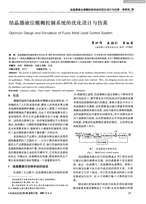
机 作 用 于 塞 棒 , 从 而控 制 钢 水液 位 1。如 图 1所 4 1
示。
图 l结 晶器 液位 控 制系 统
F g 1 Mod L v lc n rl s se i. l e e o t y t m o
K e wOr :o j o sc si g f z y c nt l ut- pt ae ;smua in y dsc n【 nu u a tn ; u z o r ;a o o i z r i lto o m
在连铸 的生产 过程 中,结 晶器 内钢水液位 高度 控 制是最 重要 的工艺操作之 一 ,它对 提高钢胚 质量 和 稳 定 生产 过 程 起着 关 键 的作 用 。在 液 位控 制 方
结 晶器 液位 通 过塞棒 上 下移 动来 控 制 中问包 水 口,
调 节 中问包 流 向结 晶器的流 量来控 制钢水 液位 。塞
棒 位置信 号来 自于液位 传感器 ,液位 传感 器通过 液
位 测量系统测 量到 的液位信 号,该信 号为 控制器 输
入 ,控 制器输 出信 号提供 给伺服 电机 ,然 后伺服 电
仿真, 仿真 结果表明, 该系统具有超调小、 稳态性能好等特点, 能满足结晶器液位 的工艺要求 。
【 关键 词 】 铸 ;模 糊控 制 ;自寻优 控 制 器 :仿真 连
[o:0 9 9 .s. 7 — 5 1 00 2 21 d i1. 66i n1 19 8 . 1. . 1 3 s 6 2 00
在连 铸 工艺 中 ,结 晶器钢 水液 位控 制 原 理 为 :
塞 棒 位 置与 钢 水 流 量 的特 性 发 生较 大 的变 化 ,另 外 ,如 果铝 量较 高 的钢 流浇注 时 ,水 口部 分粘 结 ,
从 而对钢流 起阻塞 作用 ,这 些变化无 法用确 定的数 学 关系式来 描述 ,用常规 的 PD液 位控制器 不能对 I 此 变化进 行有 效调节 , 由于 模糊控 制 比较传统 PD I 控制 具有对 过程参数 不灵敏 、鲁棒性好 ,而得 到 了 越来越 广泛 的应用 。而二维 自寻优算法 能根据 被控
V0. . 1 No2 9
J n2 1 u. 0 0
基于 MAT A L B的结晶
刘建新 ,谌海霞
( 长沙理工大学电气与信息工程 学院,湖南长沙 400) 104
【 摘 要】 分析 了结晶器液位控制原理, 论述 T- 维 自寻优模糊控制器的设计方法: - 然后在 M T A A L B软件 下对系统进行 了
C a gh Hun n, hn 0 41 h n s a, 'a C ia 4 0 1 0
Ab ta tT e p ic pe o e mod lv l o t l y tm n y e . e , h e inn rc s ft e t o d me so u z o i sr c : h r il f h l e e nr se i a a z d Th n te d sg ig po e so w - i n i n f zy lg c n t c os s l h
a t—piae i pee t . iay t i le xei n eeg e ae nMA L B T ersl hw t t h yt a u o t zr s rsne F l ,h s a depr o m d n l e mu t met w r i nbsdo T A . h eusso a tess m h s v t h e s