furuno 古野中文版C-STATION说明书IZS56350E_FELCOM15
古野BNWAS中文操作说明书BR500
操作手册船桥导航监视警报系统 (BNWAS)BR-500型号Pub. No. OZS-44610-D DATE OF ISSUE: MAY. 2012i重要注意事项概述• 设备操作员必须阅读和遵守本手册的说明。
错误的操作或维护可能导致保修失效,或造成伤害。
• 未经 FURUNO 的书面许可,不得复制本手册的任何部分。
• 如果本手册丢失或破损,请咨询经销商如何更换。
• 本手册内容和设备规格如有更改,恕不另行通知。
• 本手册中屏幕显示(或图示)范例可能与您的屏幕显示有所区别。
您所看到的屏幕取决于您的系统配置和设备设置。
• 请保留手册,以备将来参考。
• 如未经 FURUNO 授权擅自对设备(包括软件)进行任何改装/修改,保修将失效。
• 所有品牌和产品名称均为各自持有者的商标、注册商标或服务标记。
如何丢弃本产品须根据当地工业废品处理规范丢弃本产品。
如在美国处理,请参阅电子工业联盟的主页 (/),了解正确的处理方法。
如何丢弃废旧电池有些 FURUNO 产品使用电池。
如要了解您的产品是否使用电池,请参阅维护章节。
如果使用电池,请遵守以下说明。
请用胶带封住电池正负接头后再弃置,防止因短路造成燃烧或发热。
在欧盟打叉的垃圾桶标志表示禁止将所有类型的电池丢弃到标准垃圾桶或垃圾站。
请根据所在国家的法规和《电池指令 2006/66/EU 》,将废旧电池带到电池回收站点。
在美国莫比斯环符号(三箭追逐环)表示必须回收的镍镉和铅酸充电电池。
请根据当地法律将废旧电池带到电池回收站点。
在其他国家不存在电池回收标志国际标准。
其他国家如在将来制作自己的回收标志,该标志的数量将增加。
PbNi-Cd安全说明parts inside. ii安全说明iii目录前言 (vi)系统配置 (viii)1.主警报面板...............................................................................................................1-1 1.1控制钮..............................................................................................................................................1-1 1.2如何开启/关闭系统.........................................................................................................................1-1 1.3BNWAS 显示屏................................................................................................................................1-2 1.4如何调整 LCD/LED 亮度、按键背光................................................................................................1-3 1.5如何选择支援船员............................................................................................................................1-4 1.6模式..................................................................................................................................................1-4 1.7休眠期..............................................................................................................................................1-4 1.8监视警报顺序...................................................................................................................................1-5 1.9帮助区域...........................................................................................................................................1-81.9.1 系统故障指示........................................................................................................................1-81.9.2 操作性事件指示.....................................................................................................................1-9 1.10如何进行紧急呼叫............................................................................................................................1-91.11如何呼叫导航员..............................................................................................................................1-102.另选购设备...............................................................................................................2-1 2.1计时器重置面板 BR-530,BR-550..................................................................................................2-1 2.2船舱面板 BR-540.............................................................................................................................2-2 2.3运动检测器 BR-560..........................................................................................................................2-32.4闪光灯 BR-570.................................................................................................................................2-43.维护与故障排除........................................................................................................3-1 3.1维护..................................................................................................................................................3-1 3.2更换保险丝.......................................................................................................................................3-1 3.3故障排除...........................................................................................................................................3-2 3.4如何检查处理器单元/船舱面板/计时器重置面板之间的连接........................................................3-33.5主要部件的预期寿命.........................................................................................................................3-44.安装..........................................................................................................................4-1 4.1设备列表...........................................................................................................................................4-1 4.2安装注意事项...................................................................................................................................4-2 4.3主警报面板 BR-510.........................................................................................................................4-34.3.1 桌面安装................................................................................................................................4-34.3.2 嵌入式安装............................................................................................................................4-34.3.3 屏蔽膜(选件).....................................................................................................................4-4 4.4处理器单元 BR-520.........................................................................................................................4-4 4.5计时器重置面板 BR-530、机舱面板 BR-540、运动检测器 BR-560、闪光灯 BR-570(另选购单元).........................................................................................................................................................4-44.5.1 嵌入式安装............................................................................................................................4-44.5.2 舱壁安装................................................................................................................................4-5 4.6防水计时器重置面板 BR-550(选件)............................................................................................4-9 4.7布线................................................................................................................................................4-114.7.1 处理器单元..........................................................................................................................4-114.7.2 布线信息..............................................................................................................................4-134.7.3 主警报面板..........................................................................................................................4-144.7.4 计时器重置面板、机舱面板、运动检测器、闪光灯.............................................................4-144.7.5 闪光灯.................................................................................................................................4-15 ivSUMARIO4.7.6 如何装配船舱面板、计时器重置面板、闪光灯和运动检测器的电缆...................................4-15 4.8DIP 开关,旋转开关设置...............................................................................................................4-16 4.9如何调整 LED 亮度.......................................................................................................................4-17 4.10菜单设置........................................................................................................................................4-174.10.1 管理员菜单........................................................................................................................4-174.10.2 检修菜单...........................................................................................................................4-21 4.11I/O 语句信息..................................................................................................................................4-22附录1 菜单树、缩略语、JIS 电缆选用指南..............................................................AP-1规格............................................................................................................................SP-1装箱单..........................................................................................................................A-1外形图..........................................................................................................................D-1接线图..........................................................................................................................S-1索引.............................................................................................................................IN-1vvi前言尊敬的 BR-500 用户承蒙惠购 FURUNO BR-500 船桥导航监视警报系统 (BNWAS )。
古野雷达说明书5.1
5.7.2 航海图位置校正有时候航海图覆盖和雷达图像没有对齐。
这是因为在位置定位系统(GPS、Loran等)出错或在位置定位系统和雷达之间出现不同的坐标。
此时,按照以下步骤校准雷达图像和航海图。
1. 将光标放置于有效显示区域内,转动滚轮,在导视框内显示“CHART ALIGNL=OFF / EXIT”。
2. 操作跟踪球,校准雷达地图和航海图。
注意此时既不记录也不显示轨迹。
3. 按下左按钮进行设置。
“CHART ALIGN”(航海图校准)呈红色出现在屏幕右侧。
要解除航海图位置校正,在导视框内显示“CHART ALIGN L=OFF / EXIT”,然后按下左按钮,直到“CHART ALIGN”(航海图校准)从屏幕消失。
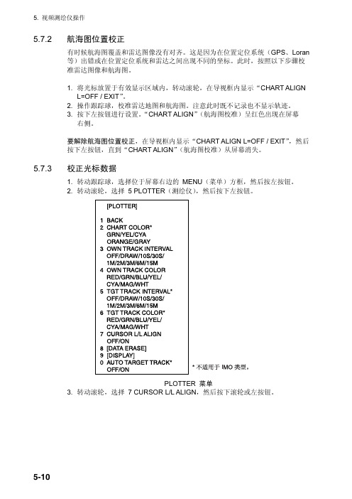
5.7.3 校正光标数据1. 转动跟踪球,选择位于屏幕右边的 MENU(菜单)方框,然后按左按钮。
2. 转动滚轮,选择 5 PL OTTER(测绘仪),然后按下左按钮。
PLOTTER 菜单3. 转动滚轮,选择 7 CURSOR L/L AL IGN,然后按下滚轮或左按钮。
4. 转动滚轮,选择 ON(开),然后按下滚轮或左按钮。
“ALIGN”(校准)呈红色出现在光标数据方框中的光标位置旁边。
(要移除校正,请选择 OFF。
如果您正在使用 AIS 功能,请选择 ON。
)5. 按两次右按钮关闭菜单。
5.7.4 航海图陆地颜色您可以按照以下步骤为航海图的陆地选择颜色:1. 转动跟踪球,选择位于屏幕右边的 MENU(菜单)方框,然后按左按钮。
2. 转动滚轮,选择 5 PL OTTER(测绘仪),然后按下左按钮。
PLOTTER 菜单3. 转动滚轮,选择 2 CHART COL OR(航海图颜色),然后按下滚轮或左按钮。
4. 选择所需颜色并按下滚轮或左按钮。
5. 按两次右按钮关闭菜单。
5.8 在视频测绘仪显示中隐藏/显示图解1. 转动跟踪球,选择位于屏幕右边的 MENU(菜单)方框,然后按左按钮。
2. 转动滚轮,选择 5 PL OTTER(测绘仪),然后按下滚轮或左按钮。
日本古野FURUNOFS操作指引
第一章日本FURUN古野公司生产的GMDS中频/高频(MF/HF)组合电台主要有三种型号,150W的FS-1570组合电台,250W的FS-2570组合电台和400W的FS-5000组合电台,下面以FURUNO FS-2570 MF/H组合电台为例介绍 FURUN组合电台的功能。
POWE电源开关):开启/断开电源。
DISTRESS遇险按钮):按住此按钮三秒以上发射遇险报警。
开始按时灯闪,大于三秒后灯亮。
收到遇险应答电报后灯灭。
如果按住此按钮少于三秒不会发射遇险报警。
CALL发射除遇险外的呼叫。
ENTER KNO输入按钮和选择旋钮):无线电话时,旋转改变 TX/RX信道、灵敏度、音量等,按一下是输入功能;DSC时,旋转选择菜单项目,按一下是输入功能。
CANCEL取消错误的数据,恢复先前的菜单,消除音响报警,取消发射,删除错误信息。
1/RT/2182 :按一下从平时值守的DSC屏幕转换到SSB无线电话设置屏幕,连续按两秒以上直接转换到的遇险无线电话通信屏幕。
2/DSC:编辑DSC发射电文。
3/TEST:进行日常试验。
4/lntCom :接通/关闭与其他控制单元FS-2570C的内部通信。
5/ACK/SQ在DSC时,改变是自动发收妥通知还是手动发收妥通知,关键点,一般不要使用自动发收妥通知,因为这样会使操作员错过许多呼叫;在SSB时,打开/关闭静噪功能。
6/SCAN在DSC的值守屏幕,启动/停止在DSC频率上的扫描值守功能。
7/喇叭:接通 /断开喇叭。
8/PRINT:打印通信日志文件、当前显示屏(除 DSC准备状态屏幕和无线电话屏幕)和测试结果。
9/灯光:调节面板亮度和液晶显示器(LCD)的对比度。
FILE/CURSO R在DSC准备屏幕打开已存储的发送文件夹,选择要发送的电文;移动光标。
#/SET UP:打开设置菜单。
ALARMT :遇险和紧急呼叫闪红灯;安全和日常呼叫闪绿灯。
OVEN丁:当主配电板电源接通时亮绿灯。
古野雷达说明书5.2
1 BACK 2 NAME
T200304109 . . . 9 NAME
R200307318 0 NEXT
READ CARD 菜单 8. 转动滚轮选择要重放的数据。 9. 按下滚轮或左按钮,重放所选数据。
在重放过程中显示消息“RD CARD DATA”(读取卡数据)。如果您选择 WR INSTALL DATA(写入安装数据),出现提示“POWER ON RESET”(打开重 置);关闭电源后再打开电源以读取安装数据。
6-3
6. 维护与故障排除
6.4
更换 GC 电路板上的电池
安装在处理器单元内 GC(电罗经)电路板上的电池可以在关闭电源时保留电罗 经数据。电池的寿命大约为 5 年。电池电压降低时,GC 电路板的诊断测试就会 显示 NG。出现这种情况时,请联络您的销售商进行更换。
GC 电路板上的电池
GC 电路板
电池类型 CR 1/2 8.L
备注 风载入 100 节
6.3
更换保险丝
显示单元的处理器单元后部的保险丝可以 保护设备避免过流(在交流设置中为过压) 和设备故障。如果无法打开电源,请先检 查保险丝。替换保险丝之前,先查明故障 原因。确认使用合适的保险丝。使用错误 的保险丝将会损害设备并导致保修失效。
船只电源和使用的保险丝
单元 处理器单元
编号 000-103-769
6.5
跟踪球维护
如果光标跳动或移动异常,请按照以下方法清洁跟踪球。
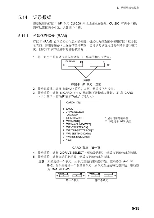
[CARD (1/2)]
1 BACK 2 DRIVE SELECT
A/B/C/D* 3 [READ CARD] 4 [WR MARK] 5 [WR NAV LINE•WPT] 6 [WR OWN TRACK] 7 [WR TARGET TRACK]** 8 [WR SETTING DATA] 9 [WR INSTALL DATA] 0 NEXT
古野雷达说明书1.1

古野FURUNO_FM8500_VHFDSC说明书

古野FURUNO FM-8500 VHF/DSC的使用介绍前述1:取消错误的遇险报警1.立即关掉发射机。
2.打开设备,放在16频道。
3.把你的船名、呼号、DSC号码向所有船作一个广播,同时取消错误的遇险报警。
例子:A L L S T A T I O N S,A L L S T A T I O N S,A L L S T A T I O N S所有船,所有船,所有船THIS IS NAME,CALL SIGN,我是XX船,呼号是,DSC NUMBER,POSITION. DSC号码是,船位,CANCEL MY DISTRESS ALERT OF 取消我于日期、UTC时间DATE,TIME UTC. 发的遇险报警=MASTER, NAME, CALL SIGN, XX轮船长DSC NUMBER, DATE, TIME UTC. 重复XX船,呼号,DSC号码,日期、时间。
前述2:系统结构图CH70天线图-1 FM-8500系统结构图FM-8500是由一个主收发单元和两根天线构成。
收发单元包括VHF发射部分、接收部分和70频道DSC值守机。
该机的性能和操作全部是由前面板控制。
一根天线用于VHF发射和接收,另一根天线用于DSC值守。
第一节VHF 无线电话各旋钮功能1.1 控制,指示控制 CHANNEL/ 用于选择一个频道。
MODE 按下这个旋钮,用于在INTL 、USA 、WX 和PRIV 四种模式之间转换。
SQUELCH/ 用于静噪比。
当所选的频道没有人讲话时,自动降低噪音,使接收机哑声。
DW/SCAN 按一下这个旋钮,可以改变操作模式:双值守,扫描和关掉这两项功能。
VOLUME/ 开机、关机和调整喇叭音量。
LOUDSPEAKER 按一下这个旋钮,用于打开和关掉喇叭。
HI/LOW key 高功率/低功率 CH16 key 16频道指示1.2 电话操作开机关机 顺时钟旋转VOLUME 直到听见一声响,就可以开机;逆时钟旋转VOLUME 直到听见一声响,就可以关机。
古野雷达说明书3.2
2. 雷达观察虚像您可能会在屏幕上的两个位置看到靠近本船的同一较大目标。
其中之一是目标直接反射的真回波,而另外一个则是假回波,如下图所示,在镜像效应的作用下,船只上或接近船只的大目标会造成假回波。
例如,如果船只靠近大的金属桥,在屏幕上可能会临时出现假回波。
虚像阴影区通风井、烟囱、桅杆或起重架均可阻挡天线信号,从而削弱雷达波束的强度。
如果天线的对角大于若干度,就会形成无法探测的盲区。
在该区域内无法探测到目标。
阴影区2. 雷达观察2.3 SART(搜救雷达应答器)说明2.3.1 SART任何距离大约为 8 海里的 X-波段(3 厘米)雷达脉冲均可触发搜救雷达应答器(SART)。
每个接收到的雷达脉冲都会使其发射一个应答脉冲,此脉冲会在完整的雷达频段反复扫描。
询问时,它会首先快速扫描 (0.4 µs) 整个波段,然后开始以较慢速度 (7.5 µs) 回扫该波段,并返回至起始频率。
该过程反复执行 12 次。
在每次扫描过程中的某些点,SART 频率会与位于雷达接收器通频内的应答脉冲频率相匹配。
如果 SART 在距离内,则 12 次慢速扫描过程中的每个匹配频率都将在雷达显示屏上产生一个应答点,并显示一条由 12 个等距(大约 0.64 海里)点组成的线。
当雷达与 SART 的距离减小为大约 1 海里时,雷达显示屏也会显示快速扫描过程中所生成的 12 个应答点。
这些额外应答点(也是等距的,为 0.64 海里)散布在原始的 12 个点所组成的线周围。
它们比原始点稍微微弱并小一些。
SART2. 雷达观察2.3.2 在雷达显示屏上显示 SART 标记该雷达配备为 SART 探测对雷达实行最优化设置的功能。
这项功能可以自动调谐雷达接收器,使其偏离最佳调谐状态。
这会消除或削弱所有正常雷达回波,但由于 SART 应答信号是扫描整个 9GHz 频段,因此 SART 标记不会消除。
当雷达接近 SART,SART 标记会扩大为大弧,使大部分的屏幕变得模糊。
Furuno NMEA 2000 安装指南说明书
Furuno NMEA 2000Installation Guide1.NMEA 2000 General Overview2.Basic Network Components2.1.Starter Kit (2)2.2.Connectors and Terminators (2)2.3.Cables (2)work Designingwork Power Source and Connection Type (3)3.2.Estimated Voltage Drop and Effective Backbone Length (5)3.3.Drop Cable Length (6)3.4.Gender Distinction of Connector (6)3.5.Termination Resistor (7)3.6.Shielding (7)4.Field Programming (Instance Setup)4.1.What is Instance? (8)4.2.Device Instance Setup via NAVnet TZtouch2/ Touch3 (9)4.3.Data Instance Setup via NAVnet TZtouch2/ Touch3 (10)5.General Information and Required PGNs1. NMEA 2000 GENERAL OVERVIEWKey Points;• Network Power: 9-16V, isolated from other circuits.• Maximum Backbone Length: 100m with micro/mini(light) / 200m with mid(heavy) cable • Maximum Number of Devices per Backbone, 50 ea. • Maximum Drop Length per Drop, 6m.• Maximum Total Drop length per Backbone, 78m.• Maximum Power Capacity per Segment, 3A with light / 8A with heavy cable.MFD(TZT12F)GPS Compass(SCX20)PowerBackbone CableBackbone CableD r o p C a b l eD r o p C a b TerminatorBackbone lengthD r o p hTerminator2. BASIC NETWORK COMPONENTSNMEA2000 networks need to consist of NMEA 2000 certified devices, approved tee-connectors, and cables. FURUNO USA supplies NMEA approved components as follows.2.1. Starter KitNMEA2000 Starter KitConsists of NMEA2000 Drop Cable, 2m 1 ea.NMEA2000 Backbone Cable, 6m1 ea.NMEA2000 Power Tee, Micro F/F, 8m 1 ea.NMEA2000 Tee-Connector, Micro F/F/M 2 ea.NMEA2000 Micro Terminator, Micro Male 2 ea.PartNumberAIR-033-7452.2. Connectors and TerminatorsName NMEA2000 Tee Connector NMEA2000 Micro Terminator NMEA2000 Micro TerminatorConn.TypeMicro Female/Female/Male Micro Male Micro FemaleP/N AIR-052-531 AIR-335-791 AIR-335-7922.3. CablesName NMEA2000 Micro Cable NMEA2000 Micro Cable (Angled) NMEA2000 Powr TeeConn.TypeMicro Male/Female Micro Male/ Female, Angled Micro Female/ Female P/N1 meter 001-533-060-00 1 meter 001-105-830-108 meters AIR-335-7922 meters 001-533-070-00 5 meters 001-105-840-106 meters 001-533-080-00 10 meters 001-105-8503. NETWORK DESIGNING3.1. Network Power Source and Connection TypeThe NMEA 2000 network is designed to be electrically isolated from other circuits to prevent radio interference, so a dedicated network power source is required. The range should be 9 -16V. The network power source should be either single-point connection of a battery or one or more isolated power supplies distributed along the network, but it should not be a combination of battery and power supply connections, and each power line should have its own fuse. There are several power-connection types, and you can choose the one best suited for your system.3.2. Estimated Voltage Drop and Effective Backbone LengthMaximum Backbone length is defined by the standard but, Voltage Drop is always an important factor for actual network plaining in electrical world, without exception. The voltage drop can be calculated from the following formula, and it will determine the effective Backbone length for your system. The network diagram describing Load Equivalent Number (LEN) per device and cable lengths will be required to calculate the voltage drop. VVVV=0.1 ×NNNN×BBNN×CCCCCCCC CC RRCCRRRR RR RR CC RRRRCC•VD = Voltage Drop (V)•NL = total Network Len•BL = Backbone Length (m)•Cable Resistance = 0.0057Ω/m for light cableThe voltage drop should be less than 1.5V for 12V power networks. This is the nominal value of a 12V battery. Or less than 3.0V for 13.8V power which is typical power voltage from an isolated power supply.A simplified graph indicating effective Backbone length vs Total LEN is shown below.(Orange area is overlapped on the Blue area.) If the cable length of your system is positioned in the masked area in the graph (based on your power source), the length should be fine.This method should not be applied to multiple power supply network, and you might need to use the detailed diagnosis method defined by NMEA 2000 standard.3.3. Drop Cable LengthThe Drop Cable is a cable between the backbone and a device, and each cable length should not exceed 6 meters for stable communication. Additionally, the Total Drop Length per backbone should be under 78 meters.3.4. Gender Distinction of connectorCommonly female connectors are placed at the power supply side and male connectors are used at the power consuming side to prevent inadvertent touching of live conductors in theelectronics world. You can always find a male connector on FURUNO NMEA 2000 device.NMEA 2000 Tee connector is designed to have devices connect to the center Femaleconnector, and female and male connector at the sides should be used as backbone.MFD(TZT12F)D r o p C a b l eBackboneFemaleFemaleFemaleMaleFemaleTerminator TerminatorTerminator Terminator Terminator TerminatorTerminatorTerminator TerminatorDevice 0 as Device 0 asInstrument Device 0 asTank SensorDevice 2 asNAVI&GPS4.2. Device Instance Setup via NavNet TZTouch2/Touch31) Home-> Settings-> Initial Setup-> Sensor List2) Open “Sensor List”, found under Initial Setup3) Select the product4) Tap on Device Instance of sensor, then a keypad appears.5) Enter the device instance to ensure there is no conflict with other devices which outputthe same PGNs.6) Some devices require a power cycle to apply the change.4.3. Data Instance Setup via NavNet TZTouch2/Touch3NavNet TZTouch2/Touch3 has ability to configure data instance for applicable FURUNO NMEA 2000 devices, i.e. IF-NMEAFI as of right now. This menu is available when using IF-NMEAFI software version 1.02 or later.1) Connect an IF-NMEAFI to MFD via NMEA 20002) Home-> Setting-> Initial Setup IF-NMEAFI Setup3) Select an IF-NMEAFI under “Select IF” menu found in “Initial Setup” on MFD. Pleasemake sure to connect only one IF unit If you have two or more on the boat.4) Tap a keyboard icon at “Fluid Instance”, then keypad appears.5) Enter the fluid instance (0 – 14) to not conflict with other Tank sensor devices.5. GENERAL INFORMATION AND REQUIRED PGNSMulti-Function Displays and Remote displays can use NMEA2000 sensors as a direct source or calculation source for on-screen information. This following table explains general information and required PGNs. Note that the product must have the receiving capabilities for the PGN and that this is varied per product. Please refer to the operation manual to see the detailed PGN list.Information Required PGNs for MFDs(PGNs for Instrument displays)NotesNavigation DataData/Time 126992 or 129033COG – Course Over Ground 129026 or 130577SOG – Speed Over Ground 129026 or 130577Boat Position 129029HDOP 129029DPT – Depth 128267HDG – Boat Heading 127250 or 130577CTW – Course Through Water 129026 or 130577STW – Speed Through Water 128259 or 130577Set – Current Direction 129291 or 130577Drift – Current Speed 129291 or 130577ROT – Rate of Turn 129751ODO – Total Cumulative Distance 129029Roll 127257Pitch 127257Route InformationBTW – Bearing to Waypoint 129029 (129284)NEXT – Next Course 129029 (129285)TTG – Time to Go (VMC) 129029, 129026 or 130577 DTW – Distance to Waypoint 129029 (129284)XTE – Cross Track Error 129029 (129283)ETA – Estimated Time Arrival 129026 and 129029 (129284, 126992 or 129033)TTA – Time to Arrival 129026 and 129029DTA – Distance to Arrival 129029HTS – Heading to Steer 129026 and 129029 (129284)VMG – Velocity Made Good 127250, 129029, 130306, 128259 or 130577 VMC – Velocity Made Course 129026 and 129029Information Required PGNs for MFD Notes Wind and WeatherSST – Sea Surface Temperature 130310, 130311, 130312 or 130316TWD – True Wind Direction 130306TWA – True Wind Angle 130306TWS – True Wind Speed 130306AWA – Apparent Wind Angle 130306AWS – Apparent Wind Speed 130306Atmospheric Pressure 130310, 130311 or 130314Air Temperature 130310, 130311, 130312 or 130316Humidity 130311 or 130313Dew Point 130312 or 130316Wind Chill Temperature 130312 or 130316Engine and TankFuel Rate 127489RPM 127488Boost Pressure 127488Oil Pressure 127489Oil Temperature 127489Engine Temperature 127489Engine Trim 127488Alternator Potential 127489Coolant Pressure 127489Fuel Pressure 127489Engine Load 127489Engine Hours 127489Transmission Oil Pressure 127493Transmission Oil Temperature 127493Total Engine Fuel Rate 127489Fuel Level (or Tank Level) 127505Total Fuel 127505Fuel Time to Empty 127489 and 127505Fuel Distance to Empty 127489 and 127505Fuel Economy 127489, 129026 or 130577Fuel Consumption 127489, 129026 or 130577Combined NavData3-Axis Speed 130578Bold = Mandatory PGN, Nonbold = Either PGN will work。
FURUNO CH-250 Sonar Exploration 产品说明书
Modelo CH-250SONAR DE EXPLORACIONEl futuro hoy con la tecnología electrónica de FURUNO.FURUNO ELECTRIC CO., LTD.9-52 Ashihara-cho, Nishinomiya City, Japan Telephone: +81 (0)798 65-2111Telefax: +81 (0)798 65-4200, 66-4622, 66-4623TRADE MARK REGISTERED MARCA REGISTRADAq Matriz activa LCD en color de alta definición q Frecuencia: 60, 88 ó 150 KHz, a elegir q La configura ción "Caja Negra" del sis tema permit e el uso de moni tores TRC o LCD q Enganche de blanco en un banco de pescado o posici ón L/L, para un área designadaq Conmutación automá tica de la longitud de impulso con la escalaq Presentación en blanco de los ecos de un color específicoq Selección inmediata de ocho modos distintos de operación q Detección por sonido, lo que libera al operador de la continua observación de la pantalla q Menú de pesca personalizablePANTALLA LCD EN COLOR DE 10,4"Folleto No. E-381b SExplor. VerticalExplor. Círculo Completo/Sector2.Presentación LCD color TFT, 10,4" (VGA: 640x480 pixels)3.Color 8 ó 16 colores 4.Modo de Presentación(1) Exploraci ón C írculo Completo (2) 1,5 x Zoom (3) Exploraci ón vertical en abanico (4) Sonda vertical (5) Exploraci ón vertical c írculo completo (6) Exploraci ón c írculo completo e Historia (7) Exploraci ón semi-c írculo y Capas (8) Exploraci ón c írculo completo y V ídeo Ploter 5.Audio 1000 Hz 6.Potencia TX 0,8-1,2 Kw 7.Ancho de Haz (a -3 dB)60 KHz:15°(H) x 12°(V)88 KHz:11.5°(H) x 9.5°(V)150 KHz: 6.5°(H) x 6.5°(V)8.Control del TransductorInclinaci ón 0°a -180°en pasos de 3°ó 6°(expl. vertical)+5°a -90°en pasos de 1°(expl. de sector)Sector de pruebaPrueba manual o autom ática en pasos de 6°ó 12°(sector de exploraci ón 6°-360°)Enganche de Blanco Posici ón L/L o Eco 9.Interfaz NMEA 0183 Ver 1.5, 2.0 (IEC 61162-1)Entrada:DBS, DBT , DPT, GGA, GLL, HDG, HDM, MDA,MTW, RMA, RMC, VDR, VHW, VTGSalida:SSTLL 10.AlimentaciónTransceptor 12-24/32 VCC, 55 W Unidad de Casco 12/24-32 VCC, 55 W(200 W mientras sube/baja el transductor)CONDICIONES AMBIENTALES (prueba IEC 60945)Unidad Presentaci ón:-15°C a +55°CEstanqueidad:IEC IPX5, USCG CFR 46 (Unidad Pre.)ALCANCE DEL SUMINISTROEstándar1.Unidad Presentaci ón MU-100C 12.Panel de Control CH-25213.Unidad de Casco CH-254 (carrera 400 mm) oCH-255 (carrera 250 mm)14.Transceptor CH-2535.Material de instalaci ón y respetos 16.Interfaz IF-8000 (s ólo tipo "caja negra")1Opcionales1.Controlador Remoto CH-2562.Rectificador RU-1746B-23.Altavoz Externo SC-05WR4.Tanque de acero de 1 m de altura (06-007-1570), tanque de acero de1.8 m de altura (SHJ-0001), tanque de acero de 3.5 m de altura (06-007-1571), tanque FRP d 1 m de altura (SHJ-0022), tanque FRP de 1.8 m de altura (06-007-1573), tanque de aluminio de 1 m de altura (OP10-5)5.Cable NMEAMJ-A6SPF0012-050 (5 m), MJ-A6SPF0011-050 (5 m),MJ-A6SPF0012-100 (10 m), MJ-A6SPF0011-100 (10 m), 6.Sensor de Movimiento MS-100 o Clin ómetro BS-704ESPECIFICACIONES SUJETAS A CAMBIO SIN PREVIO AVISO01022N Impreso en el Jap ónFURUNO U.S.A., INC.Camas, Washington, U.S.A.Phone: +1 360-834-9300 Telefax: +1 360-834-9400FURUNO (UK) LIMITEDDenmead, Hampshire, U.K.Phone: +44 2392-230303 Telefax: +44 2392-230101FURUNO FRANCE S.A.Bordeaux-M érignac, FrancePhone: +33 5 56 13 48 00 Telefax: +33 5 56 13 48 01FURUNO ESPANA S.A.Madrid, SpainPhone: +34 91-725-90-88 Telefax: +34 91-725-98-97FURUNO DANMARK ASHvidovre, DenmarkPhone: +45 36 77 45 00 Telefax: +45 36 77 45 01FURUNO NORGE A/SÅlesund, NorwayPhone: +47 70 102950 Telefax: +47 70 127021FURUNO SVERIGE AB V ästra Fr ölunda, SwedenPhone: +46 31-7098940 Telefax: +46 31-497093FURUNO SUOMI OYHelsinki, FinlandPhone: +358 9 341 7570 Telefax: +358 9 3417 5716Escala max depende de la frecuencia. 1600 m (60 kHz), 1200 m (88 kHz), 1000 m (150 kHz).Velocidad de Exploraci ón est á sujeta a la frecuencia y escalas. Hay dos velocidades en las escalas largas.。
【二副业务】FURUNO古野电子海图用户指南分享
【二副业务】FURUNO古野电子海图用户指南分享1 IntroductionThe purpose of this guide is to provide equipment-specific information to assist users inmanaging their AVCS ENC holdings.This guide should be used in conjunction with the AVCS User Guide, as well as the ECDIS Operators Manual or other documentation as supplied by the equipment manufacturer.The actual instructions and screenshots in this guide are based on the version of theFURUNO 3000 Series ECDIS installed in the UKHO as detailed on the front cover. There maybe minor differences between certain models (i.e. screen layouts may vary).2 Data ManagementAll electronic chart licensing and data management operations are carried out through the “Charts” Option on the Top Toolbar and then from the various Tabs on the left hand side ofthe Home screen on the FURUNO ECDIS:3 The User Permit Number (UPN)The User Permit Number is a 28 character alphanumeric string that is unique to each ECDIS installation or group of ECDIS, e.g. multiple bridge installations. The User Permit Numbershould have been supplied at the time of delivery and must be used when ordering an AVCS licence.To check the 'User Permit Number’:License: ENC → ENC User Permit → ENC User Permit’ Box1. Select 'License’ on the Home screen2. In the 'Licenses’ window, select 'ENC User Permit’The User Permit then appears in the 'ENC User Permit’ Box.4 Deleting ENC DataNew AVCS customers who had previously subscribed to other ENC services are strongly recommended to remove (purge) all ENC Permits and ENCs from the system before installing AVCS. For more information please refer to the 'Data Cleansing’ section in the AVCS UserGuide.Deleting 1 Chart OnlyManage Charts: Select Chart to be deleted → Delete Charts1. Select 'Manage Charts’ on the Home screen2. In the 'Manage Charts’ window, tick the Chart to be deleted3. Click on 'Delete Charts’An 'Attention’ window with the message “All selected Charts will be deleted. Do you wish to continue?” is then displayed. Click 'OK’ to confirm the deletion of the selected Chart.A final 'Attention’ window then confirms the deletion. Click 'OK’.The deleted Chart will disappear from the 'Licenses’ window.Deleting ALL ChartsManage Charts:Right-click to left of Type box → Select All → Delete Charts1. Select 'Manage Charts’ on the Home screen2. In the 'Manage Charts’ window, right-click the block to the left of the 'Type’ box.3. 2 options then appear 'Select All’ and 'Deselect All’. Click on 'Select All’.4. When all Charts are selected with a Tick in front of them, click on 'Delete Charts’An 'Attention’ window with the message “All selected Charts will be deleted. Do you wish to continue?” is then displayed. Click 'OK’ to confirm the deletion of all the selected Charts.A final 'Attention’ window then confirms the deletion. Click 'OK’.The deleted Charts will disappear from the 'Manage Charts’ window.5 Deleting ENC PermitsIf the user has previously subscribed to another ENC service it is advised to remove these ENC permits from the ECDIS system before use. The user must select the cells for which permits are to be deleted. In most instances this will simply involve selecting all cells. In certain circumstances it may be required to remove permits for individual cells, in this case simply select the cells for which permits need to be deleted.Deleting 1 Permit onlyLicense: ENC → Select Permit to be deleted → Delete Licenses1. Select 'License’ on the Home screen5. In the 'Licenses’ window, select the Chart for which the Permit is to be deleted, with a Tick in front of them6. Click on 'Delete Licenses’An 'Attention’ window with the message 'Selected group will be deleted. Do you wish to continue?’ is then displayed. Click 'OK’ to confirm the deletion of all the selected Charts.A final 'Attention’ window then confirms the deletion: '1 ENC Permit removed’. Click 'OK’. The deleted Chart will disappear from the 'Licenses’ window.Deleting ALL PermitsLicense: ENC → Select All Permits → Delete Licenses1. Select 'License’ on the Home screen2. In the 'Licenses’ window, right-click the block to the left of the 'Type’ box.3. 2 options then appear 'Select All’ and 'Deselect All’. Click on 'Select All’.4. Once all the Permits to be deleted are selected with a tick in front of them, click 'Delete Licences’ on this 'Licenses’ window.An 'Attention’ window with the message “Selected group will be deleted. Do you wish to continue?” is then displayed. Click 'OK’ to confirm the deletion of all the selected Charts.A final 'Attention’ window then confirms the deletion: 'XXX ENC Permits removed’. Click 'OK’. The deleted Charts will now disappear from the 'Licenses’ window.6 The Public KeyThe Admiralty Vector Chart Service currently uses the IHO.CRT, issued by the International Hydrographic Organisation, to authenticate its AVCS ENCs. However, the Furuno 3000 ECDIS uses the IHO.PUB Public Key which is included in all AVCS Media.To view the installed Public KeyPublic Key: Select Public Key window → Display Content1. Select 'Public Key’ Menu on the Home screen2. In the 'Select Public Key’ window appearing, when a Public Key is already activated, an 'A’populates the box next to the selected Public Key3. Click on 'Display Content’ to view the already activated Public KeyTo install a new Public KeyPublic Key: Select Public Key window → Load New Key1. Select 'Public Key’ Menu on the Home screen2. In the 'Select Public Key’ window appearing, click on 'Load New Key’ to install a new Public KeyOn the next 'Open File’ window, select the location where the new Public Key to install is stored (i.e. CD, DVD, USB). Select the IHO.PUB and click 'Open’.An 'Attention’ message confirming the installation of the new Public Key will appear on the screen. Click 'OK’.3. Highlight the new Public Key and select 'Activate’ to select the required Public Key to be installed4. An 'A’ will then populate the box next to the selected Public Key.5. Click 'Close’ to finish.7 Installing ENC PermitsTo install AVCS ENC Permits:License: Licenses → ENC Tab → Install Licenses → Select File window → Permit.txt file →Open → OK1. Select 'License’ on the Home screen and in the 'Licenses’ window, select the 'ENC’ Tab2. Select 'Install Licenses’In the next 'Select File’ window, highlight the Permit.txt file from the selected source location (i.e. USB), click 'Open’ and then 'OK’If needed, the Permit List can then be exported to external Media (i.e. CD, DVD, USB) by clicking on the 'Export List’ option:8 Installing AVCS Base CDsThere are currently 9 AVCS Base CDs but this number will grow as more ENCs become available for distribution within AVCS. It is unlikely that users will need to install all of the CDs in order to load all licensed ENCs. Reference to the Schedule A can avoid the unnecessary loading of some CDs and save the user time.The process described here should be used in almost all circumstances as it will automatically select data to be loaded according to the permit file installed by the user.Note: Ensure the latest permits have been installed before attempting to install any dataAuto Load: Search File Media → OK → Install Chart Data1. After having inserted the first AVCS Base CD identified in the Schedule A into the appropriate drive (i.e. D/Q), click on 'Auto Load’ on the Home screenAn 'Attention’ window then appears warning that 'this process takes time to complete and the operation speed of the system will decline. Do you wish to continue?’. Click 'OK’.Another 'Attention’ window confirms how many 'Charts are contained in the inserted AVCS Media and how many can be installed (based on the previously installed Permit file). Do you wish to continue?’. Click 'OK’.Note: Whenever Charts are cancelled, they will automatically be removed from the system. When this happens, this will be communicated in the 'Error/Warning Guidance’ window at the end of the installation.The AVCS Media will be read and a progress Bar will display on the 'Install Chart Data’ window on the screen.When the installation is complete, a window confirming the installation will appear, click'Confirm’(this window can take some time to appear even if the Progress Bar shows a completion rate of 100%)To check the details of the data installation, click on 'Show Details’ on the 'Install Chart Data’window. Click 'Finish’ to close. This process should be repeated until all required Base CDs have been installed.Note: Make sure that all the required AVCS Base CDs have been inserted and the import operations completed before installing the latest Update CD. Updates cannot be applied unless the ENC base file is present in the system database.9 Installing AVCS Update CDThe Weekly AVCS Update CD must only be inserted into the CD Drive after having installed the latest required Base CD(s).Insert the latest AVCS Update CD into the appropriate Drive (i.e. D/Q)Note: Base CDs are re-issued about every 6 to 8 weeks. The AVCS Update disc will indicate which Base disc week must have been installed. It is important that users do not attempt to load an Update CD that is not consistent with the Base CDs.Auto Load: Search File Media → OK → Install Chart Data1. Click on 'Auto Load’ on the Home screenAn 'Attention’ window then appears warning that 'this process takes time to complete and the operation speed of the system will decline. Do you wish to continue?’. Click 'OK’.Another 'Attention’ window confirms how many 'Charts are contained in the inserted AVCS Media and how many can be updated (based on the previously installed Permit file). Do you wish to continue?’. Click 'OK’.Note: Whenever Charts are cancelled, they will automatically be removed from the system. When this happens, this will be communicated in the 'Error/Warning Guidance’ window at the end of the installation.The AVCS Media will be read and a progress Bar will display on the 'Install Chart Data’ window on the screen.When the installation is complete, a window confirming the installation will appear, click'Confirm’(this window can take some time to appear even if the Progress Bar shows a completion rate of 100%)To check the details of the data installation, click on 'Show Details’ on the 'Install Chart Data’window. Click 'Finish’ to close.10 Installing AVCS DVDWhen using the AVCS DVD Service, only one disc needs to be installed because it contains all the Base ENCs and Updates up to the date of its issue.Insert the latest AVCS DVD into the appropriate Drive (i.e. D/Q)Note: The loading process within the ECDIS will be very similar to that required for the AVCS CD Service however there are some minor differences which are detailed belowAuto Load: Search File Media → OK → Install Chart Data1. Click on 'Auto Load’ on the Home screenAn 'Attention’ window then appears warning that 'this process takes time to complete and the operation speed of the system will decline. Do you wish to continue?’. Click 'OK’. Another 'Attention’ window confirms how many 'Charts are contained in the inserted AVCS Media and how many can be installed (based on the previously installed Permit file). Do you wish to continue?’. Click 'OK’.Note: Whenever Charts are cancelled, they will automatically be removed from the system. When this happens, this will be communicated in the 'Error/Warning Guidance’ window at the end of the installation.The AVCS Media will be read and a progress Bar will display on the 'Install Chart Data’ window on the screen.When the installation is complete, a window confirming the installation will appear, click'Confirm’(this window can take some time to appear even if the Progress Bar shows a completion rate of 100%)To check the details of the data installation, click on 'Show Details’ on the 'Install Chart Data’window. Click 'Finish’ to close.11 Installing AIO PermitsThe Admiralty Information Overlay (AIO) is installed in the Furuno FMD 3000 ECDIS by installing the Cell GB800001 included in the PERMIT.TXT file and then the AIO Data.To install the AIO Permits:License: Licenses → ENC Tab → Install Licenses → Select File window → Permit.txt file →Open → OK1. Select 'License’ on the Home screen and in the 'Licenses’ window, select the 'ENC’ Tab2. Select 'Install Licenses’In the next 'Select File’ window appearing, highlight the Permit.txt file which contains the AIO Permit from the selected source location (i.e. USB), click 'Open’ and then 'OK’3. The AIO Permit will now appear in the Licenses List12 Installing AIO CDThe AIO Media can only be installed when the usual AVCS S-63 1.1 Data has been previously installed. After having previously installed the Permit for the AIO Cell GB800001, the AIO Media now needs to be installed.Insert the latest AIO CD into the appropriate drive (i.e. D/Q)Auto Load: Search File Media → OK → Install Chart Data1. Click on 'Auto Load’ on the Home screenAn 'Attention’ window then appears warning that 'this process takes time to complete and the operation speed of the system will decline. Do you wish to continue?’. Click 'OK’.Another 'Attention’ window confirms how many 'Charts are contained in the inserted AVCS Media and how many can be installed (based on the previously installed Permit file). Do you wish to continue?’. Click 'OK’.The AIO CD will be read and a progress Bar will display on the 'Install Chart Data’ window on the screen.When the installation is complete, a window confirming the installation will appear, click'Confirm’(this window can take some time to appear even if the Progress Bar shows a completion rate of 100%)To check the details of the data installation, click on 'Show Details’ on the 'Install Chart Data’window. Click 'Finish’ to close.2. Once the AIO Permits and Media have been installed, the AIO is enabled3. If needed, the system will give the user the option of then disabling the AIO from the'Licenses’ window:13 Systems ChecksThe user has the option to review the status of all installed ENCs on the Furuno FMD 3000 ECDIS by consulting various Reports.1. Select 'Record’ on the Home screen2. Select 'Chart Log’3. Select 'ENC’A Report containing all the installed Cells then appears on the screen. This Report contains information about all the Update status of the Cells currently installed on the system. Select 'Close’ to close the Report.The Furuno FMD 3000 ECDIS displays the Cell status of the Cells installed within a colour coding system on the Geographical Display:Green: The Permit is valid and the ENC is available for use in SENC format. If the source of the ENC is a RENC, then the ENC is also up-to-date. If the source of the S-57 vector chart is something other than a RENC then all loaded updates are included into the SENC.Orange: You have a valid Permit and the ENC is available for use in SENC format but it is either not up-to-date or has been cancelled. This could be for several reasons, either the SENC is from a previous edition, the latest SENC update was missed or the ENC has been cancelled.Red: If an ENC is installed in the SENC but does not have a corresponding permit installed then the ENC is no longer available for display in the viewer.Blue: The conversion of the Cells from RENC to SENC as somehow failed during the conversion process. This can be due to a software upgrade or an issue with the data itself preventing the Furuno from successfully converting to SENC. For example, one Cell was up-to-date before a software upgrade and was not updated when the software was upgraded. Then the Cell would show as blue until the conversion process is completed. Contrary to the Magenta colour which means that the RENC to SENC conversion was not even started. Magenta: You have a permit to use the ENC, but the installed ENC is not available in SENC format and thus you cannot use the ENC currently.It is also possible to check the updating status of all Cells installed within the Cell Status mode:1. Select 'Cell Status’ on the Home screen2. The 'Cell Status’ window then appears displaying the Updating status of all Cells installed: If screenshots need to be taken (i.e. report specific issues), this is carried out in the Furuno FMD 3000 by clicking on 'Capture Screenshot’ on the Home screen.When the required screenshot is taken, it will be automatically saved on the system within the 'Settings’ Tab on the top MenuIn the next 'Settings’ window, find the screenshot previously taken (usually at the bottom of the drop down list), highlight it with a tick on its left hand side and then click on 'Export’. This will open a new window where you can then save this screenshot on the preferred source location (i.e. USB).14 TroubleshootingMany of the difficulties that could be experienced when using the Admiralty Vector Chart Service with this system can be avoided by carefully following the instructions in this guide. However, issues that are known to have caused confusion in the past are detailed in the Frequently Asked Questions (FAQ) section which can be found at:If you encounter problems that are not solved by referring to the FAQs, you may wish to seek Technical Support. Please see the section below for contact details.Who should you contact?You will receive the most effective support if you address your initial query to either yourECDIS Manufacturer or ADMIRALTY Chart Agent, but in certain circumstances you may need to contact the UKHO Customer Services.When reporting a chart related problem it is useful if you can provide the following details:> Licence number> Vessel name> ECDIS/Software Manufacturer> Details of error message – Including 'SSE’ error code> Screen shot(s) of error> Details of Base Discs used (date)> Details of Update CD used (date)> Details of Permits used (date)> Details of Cell number(s) errors apply to> Have there been any configuration changes to system(s)> Details of User Permit(s) and PIN Number(s)Emergency Chart Permit GenerationIn certain circumstances it may be necessary for a vessel to get access to an AVCS chart at very short notice, for instance if a route needs to be diverted due to a medical or safety emergency.In these emergency circumstances only, individual AVCS ENC Permits can be obtained from the UKHO 24 hours a day, 365days a year.To obtain the AVCS emergency permit, please quote:> Vessel Name> ECDIS User Permit Number> Required ENCsThe permits can be sent directly to the vessel by email wherever possible, by fax, or simply by reading the characters out over the telephone or radio.Please contact UKHO Customer Services using the contact details below:。
- 1、下载文档前请自行甄别文档内容的完整性,平台不提供额外的编辑、内容补充、找答案等附加服务。
- 2、"仅部分预览"的文档,不可在线预览部分如存在完整性等问题,可反馈申请退款(可完整预览的文档不适用该条件!)。
- 3、如文档侵犯您的权益,请联系客服反馈,我们会尽快为您处理(人工客服工作时间:9:00-18:30)。
Pub. No. I ZS-56360-E DATE OF ISSUE: DEC. 2008目录设备清单 (iii)系统配置 (iv)1. 安装 (1)1.1 天线单元 (1)1.2 终端机 (7)1.3 遇难报警/确认收信单元 IC-305/警报单元 IC-306 (9)1.4 打印机 PP-510(可选)/EGC 打印机 PP-505(可选) (10)1.5 AC/DC 电源单元 PR-240(可选) (10)1.6 接线盒 IC-315 (11)2. 布线 (12)2.1 终端机上的天线电缆接头 (13)2.2 遇难报警/确认收信单元 IC-305 (15)2.3 警报单元 IC-306 (16)2.4 接线盒 IC-315 (17)3. 初始设置 (18)3.1 设置 IMN(INMARSAT 移动识别码) (18)3.2 外部设备设置 (19)4. 安装 GPS 电路板(可选) (20)5. 更改电源规格 (23)装箱单.............................................................................................................................A-1外形图.............................................................................................................................D-1接线图.............................................................................................................................S-1设备清单标准配件 名称型号 编号 数量备注 天线单元IC-115 - 1 终端机IC-215 - 1 遇难报警/确认收信单元IC-305 - 1 警报单元IC-306 - 1接线盒 IC-315 - 1 w/CP16-02501*CP16-02101 004-439-060 用于 30 米电缆,天线单元*CP16-02111 004-439-070用于 50 米电缆,天线单元* CP16-02121 004-439-080 1 套用于 100 米电缆,天线单元*CP16-02300 000-043-433 1 套CP16-02301(用于 IC-215)*, CP16-02302(用于键盘)*CP16-02201 004-438-890 1 套用于 IC-305/306TP5FBAW-5DFBB 000-159-523-1130 米天线电缆8D-FB-CV 000-117-599 50 米天线电缆 安装材料 12D-SFA-CV 000-138-866 1100 米天线电缆附件FP16-00600 000-043-434 1 套 迷你键盘 (BTC-5100C),FD (FP16-00601)备件SP16-01301 004-439-370 1 套 保险丝* 选用件 名称型号 编号 数量 备注FD-ROM 16-5-0164 004-438-920 1 套GPS 电路板 OP16-47 001-017-110 1 套GPS 电路板套件 OP16-48 000-011-766 1 套RF 盖 (GPS) OP16-49 000-011-767 1EGC 打印机 PP-505 - 1打印机 PP-510 - 1 w/CP16-01200*AC/DC 电源单元 PR-240 - 1 w/CP24-00151*000-560-452用于接线盒,10 米000-103-868用于接线盒,20 米 000-103-869用于接线盒,30 米 000-132-829用于接线盒,40 米5 组对绞线 CO-SPEVV-SB-C 0.2x5P 000-132-828 1 用于接线盒,50 米SSAS 修正包** OP16-33 000-043-492 1 IC-307(2 件),FD-ROM(用于 RFCON CPU ,用于TERM CPU )SSAS 警报单元** IC-307 000-043-473 1 w/CP16-03101, FP16-00901OP16-27 004-448-000 1 用于遇难报警/确认收信单元,警报单元嵌入安装工具包 OP16-28 004-448-010 1 用于 SSAS 警报单元ALC (FFA) 修正包* OP16-26 004-439-840 1俄语套件 OP16-43 004-449-590 1 用于 IC-215PC 终端机软件 OP16-45 004-449-600 1 俄语天线安装套件 CP16-03701 004-555-000 1 套天线支架 CP16-03702 001-016-260 1 参阅第 D-14 页。
天线安装铁管 CP16-03703 001-014-510 1*: 请参阅本手册背面的装箱单。
**: SSAS 需要 SSAS 修正包。
安装三个 IC-307 需要额外的 SSAS 警报单元。
系统配置1.安装1.1 天线单元安装位置•将全向天线单元安装于桅杆之上附近不可以有遮挡物,及不可以在雷达天线转动的范围。
理想的安装位置的前后方向向下 5 度和左右舷向下 15 度方向应没有障碍物。
此概念如下图所示。
天线桅杆、鞭状天线等的阴影区域应位于距离天线单元一米处的两度之内。
天线单元安装位置•如果既安装了 Inmarsat-B/F 又安装了 Inmarsat-C 船只地面站,请将 Inmarsat-B/F 天线与 Inmarsat-C 天线隔开至少 8 米。
•按下图所示将天线单元和 S 波段雷达分开:S 波段雷达和安装区域1. 安装该单元•Inmarsat 指定的允许振动级别如下表所示。
允许震动级别频率 级别2 到 10 Hz 2.54 毫米峰值振幅10 到 100 Hz9.8 m/s² 峰值加速度•避开通风井和烟囱附近的位置;天线罩上的烟灰会降低信号级别。
•将天线单元和 HF、VHF 或 27 MHz 天线分开 5 米。
安装有 30、50 或 100 米的天线电缆可用(要在购机前指定长度)。
30 米电缆两侧都有接头,安装铁管和一个用于 50/100 米电缆的接头。
切勿缩短这些电缆以防止干扰。
安装天线单元需要专用。
注意:要使用天线安装套件安装天线单元(型号:CP16-03701,编号:004-555-000),请参阅第 D-13 页。
自行准备一根带接地桩的天线桅杆(天线桅杆上焊接有 M6 不锈钢螺栓),以及带有螺纹和安装板的安装铁管(请参阅下面的安装板外形图。
)将安装铁管焊接至天线桅杆上。
接地桩与天线单元上的接地端子之间的距离应在 340 毫米之内,这也是配件的地线长度。
安装铁管和天线桅杆1. 安装该单元15 或 30 米电缆1. 在安装铁管的螺纹上涂抹硅树脂密封剂(自供应)。
2. 松开三颗螺丝,将天线基座从天线单元上移除。
3. 将天线电缆依次穿过安装铁管和天线基座。
4. 将电缆保护器(附带)插入天线基座底部的插槽。
5. 旋转天线基座将其拧在天线安装铁管上。
6. 将天线电缆穿过收缩管(SCM2,附带)。
7. 将天线电缆连接至天线单元(上部)底部的接头上。
8. 移动收缩管直至接触到天线单元(上部)底部。
9. 加热上述收缩管,然后在收缩管的上边缘涂抹硅酮橡胶。
同时在收缩管的下边缘缠上自粘接带,然后用乙烯基胶带包裹自粘接带。
注意:天线单元(上部)的底部与缠绕部分的末端之间应小于 50 毫米。
天线单元,将电缆穿过安装铁管1. 安装该单元10. 重新将天线单元(上部)安装于天线基座上。
(扭矩:2.6 N·m ± 10%)11. 在天线基座和安装铁管的连接部位包裹自粘接带,然后在自粘接带上缠绕乙烯基胶带。
这些胶带都应缠紧。
12. 将地线 RW-4747(附带)固定于天线单元上的接地端子与船只的接地点之间。
安装13. 将硅酮胶(附带)涂抹于天线基座底部的接地端子和三颗螺丝上。
14. 使用扎线带(自供应)将天线电缆固定在桅杆上。
1. 安装该单元50 或 100 米电缆1. 在安装铁管的螺纹上涂抹硅树脂密封剂(自供应)。
2. 松开三颗螺丝,将天线基座从天线单元上移除。
3. 将电缆组件 TPA5FB0.3NJ5FBA-5DFB(附带,300 毫米)穿入收缩管(SCM2,附带)。
4. 将上述电缆组件连接至天线单元(上部)底部的接头上。
5. 向上移动收缩管直至接触到天线单元(上部)底部。
6. 加热收缩管,然后在收缩管的上边缘涂抹硅酮橡胶,同时在收缩管的下边缘缠上自粘接带,然后用乙烯基胶带包裹自粘接带。
注意:天线单元(上部)的底部与缠绕部分的末端之间应小于 50 毫米。
7. 将电缆保护器(附带)插入天线基座底部的插槽。
8. 将天线电缆依次穿过安装铁管和天线基座。
当在安装铁管旁边放置电缆时,请将电缆放于一边,以让其穿过天线基座的突出部分。
请参阅下图中的 [A]。
防水性能9. 重新将天线单元(上部)安装于天线基座上。
(扭矩:2.6 N·m ± 10%)10. 旋转天线单元将其拧在天线安装铁管上。
11. 在天线基座和安装铁管的连接部位包裹自粘接带(附带),然后在自粘接带上包裹乙烯基胶带。
12. 将接地线 RW-4747(附带)固定于天线单元上的接地端子与桅杆上的接地桩之间。
1. 安装该单元13. 连接天线电缆(50 或 100 米)和电缆组件(在步骤 5 中已连接)。
14. 用自粘接带包裹接头,然后用乙烯基胶带包裹自粘接带。
用扎线带(自供应)绑紧电缆末端。
15. 使用扎线带(自供应)将电缆固定在桅杆上。
安装防水性能1. 安装该单元1.2 终端机选择以下位置安装终端机。
•温度和湿度应适中且稳定。
•为了方便维护和检查,应在装置的背面和侧面保留充足的空间且不要绷紧电缆。
安装桌面安装1. 用四颗自攻螺丝(型号 5x20,附带)将挂钩固定于桌上。
80 + 0.529 + 3终端机,桌面安装2. 将旋钮和垫圈轻轻旋入终端机。
3. 将终端机安装到悬架,然后固定旋钮。
嵌入式安装当舱壁厚度介于11 至 14 毫米时,使用自供应的平头螺丝 (M4x20)。
当舱壁厚度超过 14 毫米时,平头螺丝的长度应为舱壁厚度 A +7.8±2 毫米。
同时,B 的长度最大为 8 毫米(B≤8 毫米)。
BA舱壁,切面图1. 在安装位置设计一个开口,其尺寸如下一页所示。