ST02CM-2-E规格书_v1[1].0
CM 202E 电子烟机说明书
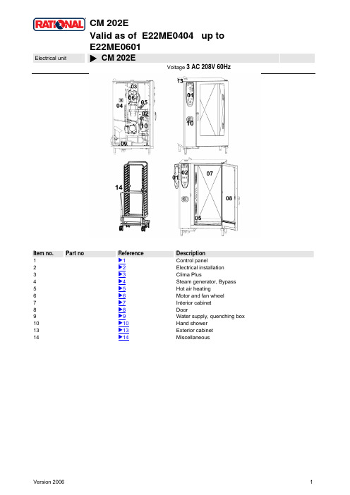
CM 202EValid as of E22ME0404 up toE22ME0601Electrical unit X CM 202EVoltage 3 AC 208V 60HzItem no. Part no Reference Description1 X1Control panel2 X2Electrical installation3 X3Clima Plus4 X4Steam generator, Bypass5 X5Hot air heating6 X6Motor and fan wheel7 X7Interior cabinet8 X8Door9 X9Water supply, quenching box10 X10Hand shower13 X13Exterior cabinet14 X14MiscellaneousCM 202EElectrical unit X Table of contentsVoltage: 3 AC 208V 60Hz1 Control panel (3)1.A Control panel (4)2 Electrical installation (5)2.A Contactor assembly (6)3 Clima Plus (8)4 Steam generator, Bypass (9)4.A Pump connection spout cpl (10)4.B Venting valve for steam generator (11)5 Hot air heating (12)6 Motor and fan wheel (13)7 Interior cabinet (14)7.A Interior cabinet welded (15)7.B Gasket frame w. glass a. gaskets (16)7.C Air baffle (17)7.C Air baffle (18)8 Door (19)8.A Door (21)8.C Door catch (22)9 Water supply, quenching box (23)10 Hand shower (24)13 Exterior cabinet (25)13.A Exterior cabinet (26)14 Miscellaneous (27)Electrical unit X 1 Control panel 11 Control panel Voltage 3 AC 208V 60HzItem no. Part no Reference DescriptionA X1.A Control panel1 87.00.001Control panel insert with overlayElectrical unit X 1.A Control panel 11 Control panel Voltage 3 AC 208V 60HzItem no. Part no Reference Description1 42.00.004 Control pcb Index "ME"2 1104.0121Hex nut M4 self locking3 10.00.355Spacer black4 2020.0400Fixing device for cable harness5 16.00.282Dial6 40.02.087 Buzzer6 3006.0107 Buzzer7 5110.1028 Gasket poti hot air, core temperature8 40.00.464Potentiometer CT9 16.00.387Mounting device f.sealing + sealing lip10 1306.0218Washer A4,311 1103.0122Hex nut M3 self-locking12 5110.1029Gasket mode switch13 5110.1027Distance plate for front panelElectrical unit X 2 Electrical installation 22 Electrical installation Voltage3 AC 208V 60HzItem no. Part no Reference DescriptionA X2.A Contactor assembly1 4007.0620Membrane DGC 292 10.00.418 Bundle guide big3 40.00.453Solid state relais4 10.00.507Pan head screw Torx 5/16" T205 10.00.444Raised countersunk head screw Torx M4x86 1106.0224Hex nut M6 self locking7 10.00.065Countersunk screw Torx T20 M4x128 1104.0122Hex combination nut M4 galv9 42.00.007 External memory10 10.00.510Grommet 10/12/16-211 1104.0801Cage nut M412 10.00.243Spacer M4x813 1104.0120Hex nut M414 10.00.112Cable clip short15 10.00.111Cable clip long16 10.00.471Cable clip d10-12mm17 40.00.338Sicotronic-terminal *screw typ*19 40.01.356Fixing device f. cable guide20 1106.0160Hex nut M621 1206.0120Tooth lock washer A6,422 40.01.132Center fixation f. contactor assembly23 40.00.471Bus cable 0.8m23 40.00.472Bus cable 1.3m26 1104.0400Rivet nut M4Electrical unit X 2.A Contactor assembly 22 Electrical installation Voltage3 AC 208V 60HzItem no. Part no Reference Description1 40.01.329Dry up protector 160°2 3014.0302Hex nut M10 for dry-up protector3 40.01.482Safety temperature limiter 365°C4 3014.0327Hex nut M10x1,05 40.00.576 Contactor CK08CA311N-M6 40.00.474Cooling fan D.C.7 10.00.238Screw Torx 4x508 3101.1008Cooling fan9 40.00.333Halogen transformer10 40.01.613Varistor11 40.00.592Transformer f. cooling fan12 1105.0120 Hex nut M513 1305.0160Washer A5,3x10mm14 4001.1203End plate for mounting rail15 2620.370233Installation rail for Contactor 100mm15 2816.1307 Installation rail for Contactor 140mm16 10.00.061Pan head screw Torx T20 M4x1217 10.00.111Cable clip long18 40.01.588Fuse SC-8A 10x3819 40.01.487Fuse holder 2pol20 10.00.364Pan head screw Torx M3x1221 4001.0217Fuse SC 60A22 40.01.489Fuse holder 3pol23 40.01.488Fuse holder 2pol24 40.01.610Earth terminal 20 WKN 70SL/U25 40.01.609Terminal block grey WKN 150/U26 40.01.611Terminal block grey WKN 70/U27 10.00.244 - Unterlegscheibe A3.228 40.00.212Cable buzzerElectrical unit X 2.A Contactor assembly 22 Electrical installation Voltage3 AC 208V 60HzItem no. Part no Reference Description28 40.01.475Cable clock switch USA28 40.00.250Cable contactor-SSR28 40.01.271Cable control harness28 40.00.243Cable control SSR28 40.00.205Cable level electrode28 40.00.219Cable SC pump28 40.00.220Cable solenoid valveElectrical unit X 3 Clima Plus 33 Clima Plus Voltage 3 AC 208V 60HzItem no. Part no Reference Description1 22.00.324Safety valve2 22.00.214 Hose d50x2023 2066.0531Hose clamp ø564 2001.0124Compression springElectrical unit X 4 Steam generator, Bypass 44 Steam generator, Bypass Voltage 3 AC 208V 60HzItem no. Part no Reference DescriptionA 8354.1320X4.A Pump connection spout cpl.B 8354.1304X4.B Venting valve for steam generator1 3002.0402Filling level electrode 90 mm2 44.00.175 Steam generator insolated3 1106.0803Hex combination nut M6 galv4 44.00.527 Heating element5 44.00.279Gasket f. heating element6 2066.0519Hose clamp 35,6mm7 2066.0526Hose clamp ø46mm8 44.00.207 Emptying pump9 1006.0762Hex screw M6x1010 1306.0222Washer A6,4x15x1,511 44.00.232Fixing device f. pump steam generator12 44.00.242Drain hose steam generator13 2066.0518Hose clamp 30mm14 40.00.291Thermocouple steam generator15 1104.0122Hex combination nut M4 galv16 44.00.362Steam hose 70x517 2066.0505Hose clamp 70-90mm18 2066.0506Hose clamp 20-32mm19 1105.0120 Hex nut M520 1205.0120 Tooth lock washer A5,321 2066.0300Hose clamp 50-70 mm22 2920.1300Level elektrode insert24 10.00.414Cable strap black 120°25 44.00.280Gasket f. heating element+Level elektrode insertElectrical unit X 4.A Pump connection spout cpl. 44 Steam generator, Bypass Voltage 3 AC 208V 60HzItem no. Part no Reference Description1 2118.1000Pump connection spout2 2120.1259Stop plug 10mm3 2066.0527Hose clamp ø14mm4 2066.0530Hose clamp ø16.4mm5 2062.0331Junction pressure hose GS 106 4005.0101Tie rap 145 mmElectrical unit X 4.B Venting valve for steam generator 44 Steam generator, Bypass Voltage 3 AC 208V 60HzItem no. Part no Reference Description1 2062.0332Receptacle for ventilation valve SG2 2069.0108Ventilation valve3 2112.1310Form hose for ventilation of steam generator4 2066.0506Hose clamp 20-32mmElectrical unit X 5 Hot air heating 55 Hot air heating Voltage 3 AC 208V 60HzItem no. Part no Reference Description1 40.00.330Mating flange f. heating assembly2 40.00.258 Heating assembly3 10.00.109Hex screw M5x234 1106.0360Cap nut M6, high shape5 1306.0222Washer A6,4x15x1,56 40.00.331Gasket f. heating assemblyElectrical unit X 6 Motor and fan wheel 66 Motor and fan wheel Voltage 3 AC 208V 60HzItem no. Part no Reference Description1 2120.1306Spacer SW19x172 22.00.123Flange f. motor shaft gasket3 22.00.120Mounting support f. gasket flange4 22.00.083 Motor shaft gasket4 5001.0207 Motor shaft gasket5 1315.0101Copper washer 6x10⁶ 1106.0220Hex nut M6 flat7 22.00.192Fan weel d340x1358 1008.0763Hex screw M8x208 10.00.565 Hex screw M8x2010 40.00.435Exhaust channel f. SSR11 40.00.274 Fan motor11 40.00.275 Fan motor12 10.00.071Hex nut M812 1108.0260Hex nut M812 10.00.710Hex nut M8 w. locking13 1208.0260Spring washer B814 1008.1005Square necked mushroom head bolt 8x40Electrical unit X 7 Interior cabinet 77 Interior cabinet Voltage 3 AC 208V 60HzItem no. Part no Reference DescriptionA X7.A Interior cabinet weldedB 40.00.091X7.B Gasket frame w. glass a. gasketsC 22.00.462 X7.C Air baffleC 22.00.298 X7.C Air baffle1 40.00.520 Screen interior cabinet sensor3 3024.0201Halogen bulb for interior cabinet 300°C4 40.00.229 Wiring interior light5 20.00.399 Door gasket6 40.01.943 Meat probe sensor6 40.02.103 Meat probe sensor6 40.00.298 Meat probe sensor7 1315.0104Copper washer 16x20x1,58 10.00.422 Hex nut M169 3014.0162Sealing cone for thermocouple10 3014.0163Gasket sleeve with nipple11 22.00.222Air baffle support12 40.00.594Thermocouple interior cabinet B113 2005.0308Outlet sieveElectrical unit X 7.A Interior cabinet welded 77 Interior cabinet Voltage 3 AC 208V 60HzItem no. Part no Reference Description1 40.00.098Reflector f. interior light2 4001.1248 Porcelain connector 2-pin interior light3 2120.1277Base for sensor connection4 1603.0167 Tubular rivet 3,2x0.25x105 10.00.041Rivet nut M5 hexagon closedElectrical unit X 7.B Gasket frame w. glass a. gaskets 77 Interior cabinet Voltage 3 AC 208V 60HzItem no. Part no Reference Description1 40.00.093Outer gasket f. interior light2 40.00.094Inner gasket f. interior light3 40.00.095Glass pane f. interior light4 40.00.096 Gasket frame f. interior light5 10.00.682 Phillips countersunk-head screw M5x16Electrical unit X 7.C Air baffle 77 Interior cabinet Voltage 3 AC 208V 60HzItem no. Part no Reference Description1 40.01.289Fixing clip core temp. cable2 1304.0160Washer A4,33 1604.0167Rivet 4x10⁴ 22.00.332Air sucking ring f. air baffle5 2760.1370Latch hook for air baffle6 10.00.515Rivet 3,2x5 A4Electrical unit X 7.C Air baffle 77 Interior cabinet Voltage 3 AC 208V 60HzItem no. Part no Reference Description1 1304.0160Washer A4,32 1604.0167Rivet 4x10³ 22.00.332Air sucking ring f. air baffle4 2760.1370Latch hook for air baffle5 40.01.289Fixing clip core temp. cable6 10.00.515Rivet 3,2x5 A46 1603.0166Rivet 3,2x7,9 CNS closed7 1603.0168Rivet 3,2x8 A48 22.00.440 Guard plate f. core sensorElectrical unit X 8 Door 88 Door Voltage 3 AC 208V 60HzItem no. Part no Reference DescriptionA 24.00.126X8.A DoorC 8514.1307X8.C Door catch1 2001.0042Loctite 243 10 ml2 2001.0046 Loctite 2723 24.00.136Door handle4 8474.1410Door lock5 1005.1901Straight pin ø5,6x166 1006.0761Hex screw M6x126 10.00.698Hex screw M6x12 w. precoat 857 1206.0261Spring washer B68 2940.1305Door bolt9 1008.1963Hex socket countersunk head screw M8x1610 2039.0309Cover cap for door11 1004.0665Allen screw M4x611 10.00.696Allen screw M4x6 w. Precoat 8512 24.00.133Door mounting support top13 1008.0768Ornamental screw M8x1614 1308.0160Washer A8,415 24.00.145Door bolt16 1008.0766Hex screw M8x3017 1308.0162Washer A8,418 24.00.048Door bolt19 1008.0769Ornamental screw M8x3020 2001.0109Compression spring21 1008.0761Hex screw M8x2522 1208.0260Spring washer B823 24.00.216Mounting braket f. door lock24 1008.0752Hex screw M5x1024 10.00.697Hex screw M5x10 w. precoat 85Electrical unit X 8 Door 88 Door Voltage 3 AC 208V 60HzItem no. Part no Reference Description25 1305.0160Washer A5,3x10mm26 10.00.099 Hex screw M8x1227 1005.1903Straight pin ø5,6x1228 1004.0906 Hex socket set screw M4x8Electrical unit X 8.A Door 88 Door Voltage 3 AC 208V 60HzItem no. Part no Reference Description1 24.00.212Inner glass pane2 24.00.147Sleeve for door bolt top3 24.00.159Door setting bolt4 24.00.503Fixing device f. magnet with magnet5 24.00.194Gasket glass pane/trolly6 24.00.178Pre heat mechanism f. door cpl.7 24.00.507Fixing device middle f.inter. glass pane8 24.00.701Additional gasket f. trolly9 24.01.259Plastic buffer 8,1mmElectrical unit X 8.C Door catch 88 Door Voltage 3 AC 208V 60HzItem no. Part no Reference Description1 5012.0711Silicone plate for door2 1006.1000 Stud bolt M6x753 1306.0550Washer A6,64 1004.0904Hex socket set screw M6x105 1106.0160Hex nut M66 2001.0119 Compression spring f. door catch7 1006.0625Allen screw M6x70Electrical unit X 9 Water supply, quenching box 99 Water supply, quenchingVoltage 3 AC 208V 60HzboxItem no. Part no Reference Description1 54.00.210Exhaust pipe2 2066.0516Hose clamp 60-80 mm3 40.00.398 Thermocouple quenching4 50.00.316Single solenoid valve5 50.00.139Single solenoid valve6 50.00.073Water distribution vert w/o roll guide con.7 50.00.072Water distribution vert roll guide con.8 50.00.277 Mounting device f. water distribution9 50.00.086Locking plate f. water distribution10 50.00.078Non return valve DW16/DN1211 1900.0202Water filter12 2067.0050Pressure hose d10mm13 2066.0205Hose clamp 8-16x9 mm SW 7mm14 8664.1301T-fitting water connection15 5110.1024Gasket for G3/4" threaded joint16 50.00.085Plug-in spring f. hand shower roll guide17 54.00.237 Inspection lid f. quenching chamber18 5012.0566Gasket quenching chamber 0-ring19 54.00.225Clamping bar20 2016.0943Quenching nozzle21 2112.1307Hose 70x5mmElectrical unit X 10 Hand shower 1010 Hand shower Voltage 3 AC 208V 60HzItem no. Part no Reference Description1 50.00.176 Hand shower roll guide2 50.00.230Connect. pipe f. hand shower roll guide3 50.00.130Hand shower4 50.00.156Clamp f. hand shower roll guide5 1107.0100Star lock ø46 50.00.135 Tulip for handshower7 50.00.544 Mounting device f. hand sh. roll guide8 50.00.290Gasket f. tulip9 50.00.297Gasket f. tulip11 50.00.548Hose ø10x2x500 f. hand shower12 50.00.537Gasket f. connect.pipe hand shower roll guide13 50.00.538O-ring f. connect. pipe f. hand shower roll guideElectrical unit X 13 Exterior cabinet 1313 Exterior cabinet Voltage 3 AC 208V 60HzItem no. Part no Reference DescriptionA X13.A Exterior cabinet1 22.00.354Spacer ring1 8450.1310 Spacer ring2 22.00.353Vent cover2 8455.1209 Vent cover3 2022.0101Grommet 18 mm4 8700.0317Floor fixing for units6 5006.0213Glue for floor fixing brackets7 5013.0100Edge protection profile10 2039.0111Foot adjustable, metal, 40 x 40Electrical unit X 13.A Exterior cabinet 1313 Exterior cabinet Voltage 3 AC 208V 60HzItem no. Part no Reference Description1 16.00.332Top cover2 1003.2265Countersunk self tapping screw 4,2x163 1104.0820Snap nut 4,2mm4 16.00.158Side panel right5 1603.0166Rivet 3,2x7,9 CNS closed6 16.00.139Side panel left7 10.00.102Hex self tapping screw B4,2x328 16.00.198Back panel9 16.00.296Front panel10 2002.0107Tension spring for front panel11 16.00.673 Air inlet filter12 2039.0331Cap for service door13 16.00.331Crossbar top14 5105.1028Gasket f. breather tube d=74mm15 16.00.360Cover f. RS232 interface16 10.00.103EJOT PT-screw KA 3.5x10¹⁷ 16.00.338 Edge protection profile18 16.00.115Rosette19 16.00.358Crossbar front panel20 40.00.454Door switch 1.65m22 16.00.384Bracket for door contact switch23 40.00.476Exhaust channelElectrical unit X 14 Miscellaneous 1414 Miscellaneous Voltage 3 AC 208V 60HzItem no. Part no Reference Description1 60.22.086 Mobile oven rack for type 202,2 1008.0760Hex screw M8x163 10.00.357Rubber plug black4 10.00.448 Phillips countersunk-head screw M5x165 1008.0750Hex screw M5x166 1006.0760Hex screw M6x167 10.00.565 Hex screw M8x208 1208.0160Tooth lock washer A8,49 1104.0400Rivet nut M410 1306.0120Washer A6,412 60.60.100Castor with brake ø125mm13 60.60.101Castor without brake ø125mm14 1603.0162 Rivet 3,2x915 42.00.030 Memory-Stick16 4019.0008 Sticker Electric/Danger17 60.60.574Positioning support f. core sensor。
微秒微电子ZL40200精密1 2 LVPECL双端输出缓冲器数据手册说明书

1FeaturesInputs/Outputs •Accepts differential or single-ended input •LVPECL, LVDS, CML, HCSL, LVCMOS •Two precision LVPECL outputs •Operating frequency up to 750 MHzPower •Options for 2.5 V or 3.3 V power supply •Core current consumption of 49 mA•On-chip Low Drop Out (LDO) Regulator for superior power supply rejectionPerformance •Ultra low additive jitter of 39 fs RMSApplications•General purpose clock distribution •Low jitter clock trees •Logic translation•Clock and data signal restoration•Wired communications: OTN, SONET/SDH, GE, 10 GE, FC and 10G FC•PCI Express generation 1/2/3 clock distribution •Wireless communications•High performance microprocessor clock distributionApril 2014Figure 1 - Functional Block DiagramZL40200Precision 1:2 LVPECL Fanout BufferData SheetOrdering InformationZL40200LDG1 16 Pin QFN TraysZL40200LDF116 Pin QFN Tape and ReelMatte TinPackage size: 3 x 3 mm-40o C to +85o CTable of ContentsFeatures . . . . . . . . . . . . . . . . . . . . . . . . . . . . . . . . . . . . . . . . . . . . . . . . . . . . . . . . . . . . . . . . . . . . . . . . . . . . . . . . . 1 Inputs/Outputs . . . . . . . . . . . . . . . . . . . . . . . . . . . . . . . . . . . . . . . . . . . . . . . . . . . . . . . . . . . . . . . . . . . . . . . . .1 Power . . . . . . . . . . . . . . . . . . . . . . . . . . . . . . . . . . . . . . . . . . . . . . . . . . . . . . . . . . . . . . . . . . . . . . . . . . . . . . . .1 Performance . . . . . . . . . . . . . . . . . . . . . . . . . . . . . . . . . . . . . . . . . . . . . . . . . . . . . . . . . . . . . . . . . . . . . . . . . . .1 Applications . . . . . . . . . . . . . . . . . . . . . . . . . . . . . . . . . . . . . . . . . . . . . . . . . . . . . . . . . . . . . . . . . . . . . . . . . . . . . 1 Change Summary . . . . . . . . . . . . . . . . . . . . . . . . . . . . . . . . . . . . . . . . . . . . . . . . . . . . . . . . . . . . . . . . . . . . . . . . . 41.0 Package Description . . . . . . . . . . . . . . . . . . . . . . . . . . . . . . . . . . . . . . . . . . . . . . . . . . . . . . . . . . . . . . . . . . . .52.0 Pin Description. . . . . . . . . . . . . . . . . . . . . . . . . . . . . . . . . . . . . . . . . . . . . . . . . . . . . . . . . . . . . . . . . . . . . . . . .53.0 Functional Description . . . . . . . . . . . . . . . . . . . . . . . . . . . . . . . . . . . . . . . . . . . . . . . . . . . . . . . . . . . . . . . . . .63.1 Clock Inputs. . . . . . . . . . . . . . . . . . . . . . . . . . . . . . . . . . . . . . . . . . . . . . . . . . . . . . . . . . . . . . . . . . . . . . . . .63.2 Clock Outputs . . . . . . . . . . . . . . . . . . . . . . . . . . . . . . . . . . . . . . . . . . . . . . . . . . . . . . . . . . . . . . . . . . . . . .113.3 Device Additive Jitter. . . . . . . . . . . . . . . . . . . . . . . . . . . . . . . . . . . . . . . . . . . . . . . . . . . . . . . . . . . . . . . . .153.4 Power Supply . . . . . . . . . . . . . . . . . . . . . . . . . . . . . . . . . . . . . . . . . . . . . . . . . . . . . . . . . . . . . . . . . . . . . .163.4.1 Sensitivity to power supply noise. . . . . . . . . . . . . . . . . . . . . . . . . . . . . . . . . . . . . . . . . . . . . . . . . . .163.4.2 Power supply filtering. . . . . . . . . . . . . . . . . . . . . . . . . . . . . . . . . . . . . . . . . . . . . . . . . . . . . . . . . . . .163.4.3 PCB layout considerations. . . . . . . . . . . . . . . . . . . . . . . . . . . . . . . . . . . . . . . . . . . . . . . . . . . . . . . .164.0 AC and DC Electrical Characteristics . . . . . . . . . . . . . . . . . . . . . . . . . . . . . . . . . . . . . . . . . . . . . . . . . . . . .175.0 Performance Characterization . . . . . . . . . . . . . . . . . . . . . . . . . . . . . . . . . . . . . . . . . . . . . . . . . . . . . . . . . . .206.0 Typical Behavior . . . . . . . . . . . . . . . . . . . . . . . . . . . . . . . . . . . . . . . . . . . . . . . . . . . . . . . . . . . . . . . . . . . . . .217.0 Package Thermal Characteristics . . . . . . . . . . . . . . . . . . . . . . . . . . . . . . . . . . . . . . . . . . . . . . . . . . . . . . . .238.0 Mechanical Drawing . . . . . . . . . . . . . . . . . . . . . . . . . . . . . . . . . . . . . . . . . . . . . . . . . . . . . . . . . . . . . . . . . . .24List of FiguresFigure 1 - Functional Block Diagram . . . . . . . . . . . . . . . . . . . . . . . . . . . . . . . . . . . . . . . . . . . . . . . . . . . . . . . . . . . . 1 Figure 2 - Pin Connections . . . . . . . . . . . . . . . . . . . . . . . . . . . . . . . . . . . . . . . . . . . . . . . . . . . . . . . . . . . . . . . . . . . 5 Figure 3 - LVPECL Input DC Coupled Thevenin Equivalent . . . . . . . . . . . . . . . . . . . . . . . . . . . . . . . . . . . . . . . . . . 6 Figure 4 - LVPECL Input DC Coupled Parallel Termination. . . . . . . . . . . . . . . . . . . . . . . . . . . . . . . . . . . . . . . . . . . 7 Figure 5 - LVPECL Input AC Coupled Termination . . . . . . . . . . . . . . . . . . . . . . . . . . . . . . . . . . . . . . . . . . . . . . . . . 7 Figure 6 - LVDS Input DC Coupled . . . . . . . . . . . . . . . . . . . . . . . . . . . . . . . . . . . . . . . . . . . . . . . . . . . . . . . . . . . . . 8 Figure 7 - LVDS Input AC Coupled . . . . . . . . . . . . . . . . . . . . . . . . . . . . . . . . . . . . . . . . . . . . . . . . . . . . . . . . . . . . . 8 Figure 8 - CML Input AC Coupled . . . . . . . . . . . . . . . . . . . . . . . . . . . . . . . . . . . . . . . . . . . . . . . . . . . . . . . . . . . . . . 9 Figure 9 - HCSL Input AC Coupled . . . . . . . . . . . . . . . . . . . . . . . . . . . . . . . . . . . . . . . . . . . . . . . . . . . . . . . . . . . . . 9 Figure 10 - CMOS Input DC Coupled Referenced to VDD/2. . . . . . . . . . . . . . . . . . . . . . . . . . . . . . . . . . . . . . . . . 10 Figure 11 - CMOS Input DC Coupled Referenced to Ground . . . . . . . . . . . . . . . . . . . . . . . . . . . . . . . . . . . . . . . . 10 Figure 12 - Simplified Output Driver. . . . . . . . . . . . . . . . . . . . . . . . . . . . . . . . . . . . . . . . . . . . . . . . . . . . . . . . . . . . 11 Figure 13 - LVPECL Basic Output Termination . . . . . . . . . . . . . . . . . . . . . . . . . . . . . . . . . . . . . . . . . . . . . . . . . . . 11 Figure 14 - LVPECL Parallel Output Termination. . . . . . . . . . . . . . . . . . . . . . . . . . . . . . . . . . . . . . . . . . . . . . . . . . 12 Figure 15 - LVPECL Parallel Thevenin-Equivalent Output Termination. . . . . . . . . . . . . . . . . . . . . . . . . . . . . . . . . 12 Figure 16 - LVPECL AC Output Termination for Externally Terminated LVPECL Inputs . . . . . . . . . . . . . . . . . . . . 13 Figure 17 - LVPECL AC Output Termination for Internally Terminated LVPECL Inputs. . . . . . . . . . . . . . . . . . . . . 13 Figure 18 - LVPECL AC-Coupled Output Termination for CML Inputs. . . . . . . . . . . . . . . . . . . . . . . . . . . . . . . . . . 14 Figure 19 - Additive Jitter. . . . . . . . . . . . . . . . . . . . . . . . . . . . . . . . . . . . . . . . . . . . . . . . . . . . . . . . . . . . . . . . . . . . 15 Figure 20 - Decoupling Connections for Power Pins. . . . . . . . . . . . . . . . . . . . . . . . . . . . . . . . . . . . . . . . . . . . . . . 16 Figure 21 - Differential Voltage Parameter. . . . . . . . . . . . . . . . . . . . . . . . . . . . . . . . . . . . . . . . . . . . . . . . . . . . . . . 18 Figure 22 - Input To Output Timing . . . . . . . . . . . . . . . . . . . . . . . . . . . . . . . . . . . . . . . . . . . . . . . . . . . . . . . . . . . . 19Change SummaryPage ItemChange1Applications Added PCI Express clock distribution.5Pin Description Added exposed pad to Pin Description.Removed 22 O hm series resistors from Figure 3 and 4.These resistor s are not required; however there is no impact to performance if the resistors are included.6, 7Figure 3 and Figure 413Figure 16Corrected LVPECL interface circuit.18Figure 21Below are the changes from the February 2013 ti the April 2014 issue:Page Item Change7Figure 4Changed text to indicate the circuit is not recommended for VDD_driver=2.5V.7Figure 5Changed pull-up and pull-down resistors from 2kOhm to 100 Ohm.Below are the changes from the November 2012 issue to the February 2013 issue:Clarification of V ID and V OD.The device is packaged in a 16 pin QFN1416642NCvddNCN Cc l k _pvddgndNCo u t 1_no u t 1_po u t 0_n81210o u t 0_pc l k _nN CNCgndFigure 2 - Pin Connections2.0 Pin DescriptionPin Description Pin # Name Description1, 4clk_p, clk_n,Differential Input (Analog Input). Differential input signals.12, 11, 10, 9out0_p, out0_n out1_p, out1_n Differential Output (Analog Output). Differential outputs.8, 13vdd Positive Supply Voltage. 2.5V DC or 3.3 V DC nominal.5, 16gnd Ground. 0 V.2, 3, 6, 7, 14, 15NCNo Connection. Leave unconnected.Exposed Pad Device GND .The ZL40200 is an LVPECL clock fanout buffer with two identical output clock drivers capable of operating at frequencies up to 750MHz.Inputs to the ZL40200 are externally terminated to allow use of precision termination components and to allow full flexibility of input termination. The ZL40200 can accept DC coupled LVPECL or LVDS and AC coupled LVPECL, LVDS, CML or HCSL input signals; single ended input signals can also be accepted. A pin compatible device with internal termination is also available.The ZL40200 is designed to fan out low-jitter reference clocks for wired or optical communications applications while adding minimal jitter to the clock signal. An internal linear power supply regulator and bulk capacitors minimize additive jitter due to power supply noise. The device operates from 2.5V+/-5% or 3.3V+/-5% supply. Its operation is guaranteed over the industrial temperature range -40°C to +85°C.The device block diagram is shown in Figure 1; its operation is described in the following sections.3.1 Clock InputsThe device can accept LVPECL, LVDS, CML, HCSL and single-ended inputs.Figure 3 - LVPECL Input DC Coupled Thevenin EquivalentFigure 4 - LVPECL Input DC Coupled Parallel TerminationFigure 5 - LVPECL Input AC Coupled TerminationFigure 6 - LVDS Input DC CoupledFigure 7 - LVDS Input AC CoupledFigure 8 - CML Input AC CoupledFigure 9 - HCSL Input AC CoupledFigure 10 - CMOS Input DC Coupled Referenced to VDD/2Figure 11 - CMOS Input DC Coupled Referenced to GroundVDD_driver R1 (kΩ)R2 (kΩ)R3 (kΩ)RA (kΩ) C (pF) 1.5 1.25 3.075open10101.81 3.8open10102.50.33 4.2open10103.30.75open4.21010Table 1 - Component Values for Single Ended Input Reference to Ground * For frequencies below 100 MHz, increase C to avoid signal integrity issues.3.2 Clock OutputsLVPECL has a very low output impedance and a differential signal swing between 1V and 1.6 V. A simplified diagram for the output stage is shown in Figure 12.The LVPECL to LVDS output termination is not shown since there is a separate device that has the same input and LVDS outputs.out_pout_nFigure 12 - Simplified Output DriverThe methods to terminate the ZL40200 LVPECL drivers are shown in the following figures.Figure 15 - LVPECL Parallel Thevenin-Equivalent Output TerminationFigure 16 - LVPECL AC Output Termination for Externally Terminated LVPECL InputsFigure 17 - LVPECL AC Output Termination for Internally Terminated LVPECL InputsFigure 18 - LVPECL AC-Coupled Output Termination for CML Inputs3.3 Device Additive JitterThe ZL40200 clock fan out buffer is not intended to filter clock jitter. The jitter performance of this type of device is characterized by its additive jitter. Additive jitter is the jitter the device would add to a hypothetical jitter-free clock as it passes through the device. The additive jitter of the ZL40200 is random and as such it is not correlated to the jitter of the input clock signal.The square of the resultant random RMS jitter at the output of the ZL40200 is equal to the sum of the squares of the various random RMS jitter sources including: input clock jitter; additive jitter of the buffer; and additive jitter due to power supply noise. There may be additional deterministic jitter sources that are not shown in Figure 19.Figure 19 - Additive Jitter3.4 Power SupplyThis device operates with either a 2.5V supply or 3.3V supply.3.4.1 Sensitivity to power supply noisePower supply noise from sources such as switching power supplies and high-power digital components such as FPGAs can induce additive jitter on clock buffer outputs. The ZL40200 is equipped with a low drop out (LDO) power regulator and on-chip bulk capacitors to minimize additive jitter due to power supply noise. The LDO regulator on the ZL40200 allows this device to have superior performance even in the presence of external noise sources. The on-chip regulation, recommended power supply filtering, and good PCB layout all work together to minimize the additive jitter from power supply noise.The performance of these clock buffers in the presence of power supply noise is detailed in ZLAN-403, “Power Supply Rejection in Clock Buffers” which is available from Applications Engineering.3.4.2 Power supply filteringFor optimal jitter performance, the device should be isolated from the power planes connected to its power supply pins as shown in Figure 20.•10 µF capacitors should be size 0603 or size 0805 X5R or X7R ceramic, 6.3 V minimum rating•0.1 µF capacitors should be size 0402 X5R ceramic, 6.3 V minimum rating•Capacitors should be placed next to the connected device power pins• a 0.3 Ohm resistor is recommended for the filter shown in Figure 20Figure 20 - Decoupling Connections for Power Pins3.4.3 PCB layout considerationsThe power nets in Figure 20 can be implemented either as a plane island or routed power topology without changing the overall jitter performance of the device.Absolute Maximum Ratings*Parameter Sym.Min.Max.Units 1Supply voltage V DD_R-0.5 4.6V 2Voltage on any digital pin V PIN-0.5V DD V 3LVPECL output current I out30mA 4Soldering temperature T260 °C 5Storage temperature T ST-55125 °C 6Junction temperature T j125 °C 7Voltage on input pin V input V DD V 8Input capacitance each pin C p500fF 4.0 AC and DC Electrical Characteristics* Exceeding these values may cause permanent damage. Functional operation under these conditions is not implied.* Voltages are with respect to ground (GND) unless otherwise statedRecommended Operating Conditions*Characteristics Sym.Min.Typ.Max.Units1Supply voltage 2.5 V mode V DD25 2.375 2.5 2.625V2Supply voltage 3.3 V mode V DD33 3.135 3.3 3.465V3Operating temperature T A-402585°C* Voltages are with respect to ground (GND) unless otherwise statedDC Electrical Characteristics - Current ConsumptionCharacteristics Sym.Min.Typ.Max.Units Notes 1Supply current LVPECL drivers -unloadedI dd_unload49mA Unloaded2Supply current LVPECL drivers - loaded (all outputs are active)I dd_load88mA Including powerto R L = 50DC Electrical Characteristics - Inputs and Outputs - for 3.3 V SupplyCharacteristics Sym.Min.Typ.Max.Units Notes 1Differential input common modevoltageV CM 1.1 2.0V2Differential input voltage difference V ID0.251V3LVPECL output high voltage V OH V DD-1.40V Measured at 10MHz4LVPECL output low voltage V OL V DD-1.62V Measured at 10MHz*The VOD parameter was measured from 125 MHz to 750 MHz.*The VOD parameter was measured from 125 MHz to 750 MHz.Figure 21 - Differential Voltage Parameter*Supply voltage and operating temperature are as per Recommended Operating Conditions5LVPECL output differential voltageV OD0.50.9VDC Electrical Characteristics - Inputs and Outputs - for 2.5 V SupplyCharacteristicsSym.Min.Typ.Max.Units Notes1Differential input common mode voltageV CM 1.1 1.6V 2Differential input voltage difference V ID 0.251V 3LVPECL output high voltage V OH V DD -1.40V 4LVPECL output low voltage V OL V DD -1.62V 5LVPECL output differential voltage*V OD0.40.9VAC Electrical Characteristics* - Inputs and Outputs (see Figure 22) - for 3.3 V supply.CharacteristicsSym.Min.Typ.Max.Units Notes1Maximum Operating Frequency 1/t p 750MHz 2input to output clock propagation delay t pd 012ns 3output to output skew t out2out 50100ps 4part to part output skewt part2part 80300ps 5Output clock Duty Cycle degradation t PWH / t PWL-2%0%2%Duty Cycle 6LVPECL Output Slew Rater sk0.75 1.2V/nsDC Electrical Characteristics - Inputs and Outputs - for 3.3 V SupplyCharacteristicsSym.Min.Typ.Max.Units NotesAC Electrical Characteristics* - Inputs and Outputs (see Figure 22) - for 2.5 V supply.Characteristics Sym.Min.Typ.Max.Units Notes 1Maximum Operating Frequency1/t p750MHz2input to output clock propagation delay t pd012ns3output to output skew t out2out50100ps4part to part output skew t part2part80300ps5Output clock Duty Cycle degradation t PWH/ t PWL-202Percent6LVPECL Output Slew Rate r sk0.75 1.2ps* Supply voltage and operating temperature are as per Recommended Operating ConditionsInputt Pt PWL t pdt PWHOutputFigure 22 - Input To Output TimingAdditive Jitter at 2.5 V*Output Frequency (MHz)Jitter MeasurementFilterTypical RMS (fs)Notes112512 kHz - 20 MHz 1122212.512 kHz - 20 MHz 803311.0412 kHz - 20 MHz 70442512 kHz - 20 MHz 65550012 kHz - 20 MHz 566622.0812 kHz - 20 MHz 43775012 kHz - 20 MHz39Additive Jitter at 3.3 V*Output Frequency (MHz)Jitter MeasurementFilterTypical RMS (fs)Notes112512 kHz - 20 MHz 1122212.512 kHz - 20 MHz 823311.0412 kHz - 20 MHz 72442512 kHz - 20 MHz 63550012 kHz - 20 MHz 526622.0812 kHz - 20 MHz 43775012 kHz - 20 MHz395.0 Performance Characterization*The values in this table were taken with an approximate slew rate of 0.8 V/ns.*The values in this table were taken with an approximate slew rate of 0.8 V/ns.* The values in this table are the additive periodic jitter caused by an interfering tone typically caused by a switching power supply. For this test, measurements were taken over the full temperature and voltage range for V DD = 3.3 V. The magnitude of the interfering tone is measured at the DUT.Additive Jitter from a Power Supply Tone*CarrierFrequency (MHz)ParameterTypicalUnitsNotes125MHz 25 mV at 100 kHz 159fs RMS 750MHz25 mV at 100 kHz82fs RMS6.0 Typical BehaviorTypical Phase Noise at 622.08 MHzTypical Waveform at 155.52 MHzInput Slew Rate versus Additive Jitter Propagation Delay versus TemperatureNote:This is for a single device. For more details see thecharacterization section.V ODversus FrequencyPower Supply Tone Magnitude versus PSRR (at 100 kHz) at 125 MHz Power Supply Tone Magnitude versus Additive Jitter (at 100 kHz) at 125 MHzPower Supply Tone Frequency (at 25 mV) versus PSRR at 125 MHz Power Supply Tone Frequency (at 25 mV) versus Additive Jitter at 125 MHz7.0 Package Thermal Characteristics*Proper thermal management must be practiced to ensure that T jmax is not exceeded.Thermal DataParameterSymbolTest ConditionValue UnitJunction to Ambient Thermal ResistanceΘJAStill Air 1 m/s 2 m/s 67.961.658.1oC/WJunction to Case Thermal Resistance ΘJC Still Air 44.1o C/W Junction to Board Thermal Resistance ΘJB Still Air23.2oC/WMaximum Junction Temperature*T jmax 125o C Maximum Ambient TemperatureT A85oC© 2014 Microsemi Corporation. All rights reserved. Microsemi and the Microsemi logo are trademarks of Microsemi Corporation. All other trademarks and service marks are the property of their respective owners.Microsemi Corporation (NASDAQ: MSCC) offers a comprehensive portfolio of semiconductor and system solutions for communications, defense and security, aerospace and industrial markets. Products include high-performance and radiation-hardened analog mixed-signal integrated circuits, FPGAs, SoCs and ASICs; power management products; timing and synchronization devices and precise time solutions, setting the world’s standard for time; voice processing devices; RF solutions; discrete components; security technologies and scalable anti-tamper products; Power-over-Ethernet ICs and midspans; as well as custom design capabilities and services. Microsemi is headquartered in Aliso Viejo, Calif. and has approximately 3,400 employees globally. Learn more at .Microsemi Corporate Headquarters One One Enterprise, Aliso Viejo CA 92656 USA Within the USA: +1 (800) 713-4113Outside the USA: +1 (949) 380-6100Sales: +1 (949) 380-6136Fax: +1 (949) 215-4996E-mail: ***************************Information relating to products and services furnished herein by Microsemi Corporation or its subsidiaries (collectively “Microsemi”) is believed to be reliable. However, Microsemi assumes no liability for errors that may appear in this publication, or for liability otherwise arising from the application or use of any such information, product or service or for any infringement of patents or other intellectual property rights owned by third parties which may result from such application or use. Neither the supply of such information or purchase of product or service conveys any license, either express or implied, under patents or other intellectual property rights owned by Microsemi or licensed from third parties by Microsemi, whatsoever. Purchasers of products are also hereby notified that the use of product in certain ways or in combination with Microsemi, or non-Microsemi furnished goods or services may infringe patents or other intellectual property rights owned by Microsemi.This publication is issued to provide information only and (unless agreed by Microsemi in writing) may not be used, applied or reproduced for any purpose nor form part of any order or contract nor to be regarded as a representation relating to the products or services concerned. The products, their specifications, services and other information appearing in this publication are subject to change by Microsemi without notice. No warranty or guarantee express or implied is made regarding the capability, performance or suitability of any product or service. Information concerning possible methods of use is provided as a guide only and does not constitute any guarantee that such methods of use will be satisfactory in a specific piece of equipment. It is the user’s responsibility to fully determine the performance and suitability of any equipment using such information and to ensure that any publication or data used is up to date and has not been superseded. Manufacturing does not necessarily include testing of all functions or parameters. These products are not suitable for use in any medical and other products whose failure to perform may result in significant injury or death to the user. All products and materials are sold and services provided subject to Microsemi’s conditions of sale which are available on request.For more information about all Microsemi productsvisit our website at TECHNICAL DOCUMENTATION – NOT FOR RESALE。
DBET (Bulb) 6,1型号温度控制器说明书

(*) DBZ-01 pocket brass 120mm, 12 x 1 DBZ-02 pocket stainless steel 120mm, 12 x 1 DBZ-16 pocket brass 120mm, 10 x 0.5 DBZ-17 pocket stainless steel 120mm, 10 x 0.5
U knob under the cover FT manual minimal reset ST manual maximum reset
7(&+1,&$/)($785(6
6HQVLWLYHHOHPHQW 'LPEXOE 'LPFDSLOODU\ &RQWDFWV
6ZLWFKFDSDFLW\ 'LIIHUHQWLDOV :RUNLQJ
Bulb, Capillary, 1- or 2-Stage
SSppeeccififcicaatitoionnssssuubbjejecct ttotocchhaannggeewwitihthoouuttnnootitcicee..||UUSSAA124000920094||PPaaggee11ooff 22
DBET (Bulb)
6,1*/($1'08/7,67$*(&$3,//$5<7+(50267$76
FUNCTION
APPLICATIONS
Temperature control by independent loads with adjustable differential in: - heating, cooling and air conditioning systems; - heating and cooling systems with dead zone. Models with setpoint adjustment by knob on or under the cover and possible range calibration.
Omega TX-M12-RTD 电阻温度传感器说明书

TX-M12-RTD-C Pt1004-20 mA47 (1,85)33(1,3)2(,78)Ø38 (Ø1,5)Los transmisores de la serie TX-M12-RTD de OMega ofrecen un rendimiento mejorado en transmisores de cabezal convencionales, con un tamaño y peso que suponen una fracción de los de estos. Los conectores M12 integrales mantienen la protección IP67 y la integridad de la conexión, en tanto que permiten un cambio sencillo y rápido del sensor. Hay dos modelos disponibles con salida de 4 a 20 ma o de 0 a 10 V CC. el calibrado predeterminado para la salida completa es de 0 a 100 °C (de 32 a 212 °F), pueden calibrarse otros rangos en el momento de la compra con cargo adicional; el módulo de programación USB opcional (USB-CONFIg-UNIT) permite al usuario final realizar el calibrado.el transmisor TX-M12-RTD es ideal para usar con las sondas RTD de las Series PR-21 y PR-22 de OMega o cualquier sonda RTD con un conector M12 estilo pin con código “a” que se conecta directamente a la entrada del sensor TX-M12-RTD. Otras sondas RTD pueden conectarse fácilmente usando los conectores de clavija montables en campo M12-R-M-FM o M12-S-M-FM que tienen conexiones de terminales roscadas.U C onectores M12 para una rápida conexiónde los sensores y la instrumentación U U sar con sensores de 2, 3 o 4 hilos Pt100,Pt500 o Pt1000U T emperatura ambiente de funcionamientode -40 a 85 °C (de -40 a 185 °F)U R ango de medición de -200 a 850 °C(de -328 a 1862 °F)U C arcasa pequeña de 38 mm de diámetro;solo pesa 100 gramos U Modelos con salida de 4 a 20 mA o de 0 a 10 V CCU Carcasa de acero inoxidable IP67Minitransmisor de temperatura con conectores M12Serie TX-M12-RTDTransmisor TX-M12-RTD-C mostrado en un tamaño más grande que el real.Dimensiones: mm (pulg.) Ø = diámetroTX-M12-RTD-C.CEspecificaciones Tiempo de actualización: 200 mS Tiempo de respuesta: 0,5 segundosTiempo de calentamiento: 1 minuto para precisión completa Conexión del sensor: M12 de 2, 3 o 4 hilos Intervalo mínimo: 25 °C Deriva térmicaPt100: 0,013 Ω/°CP t500/P t1000: 0,063 Ω/°CPrecisión: ±0,2 °C + (0,05 %) + precisiónde salida Corriente de excitación:<200 ua Efecto de resistencia conductora: 0,002 °C/ΩResistencia conductora máxima: 20 Ω por tramoEntorno operativo: de -40 a 85 °C;de 10 a 90 % RH (sin condensación)Temperatura ambiente de configuración: de 10 a 30 °C Peso: aprox. 100 g Modelos con salida de 4 a 20 mA Tipo de salida: corriente de bucle de 4 a 20 ma, 2 hilos Rango de salida: de 4,0 a 20,0 ma Conexión de salida: Conector M12Límites de salida: de 3,8 a 21,5 ma Precisión: salida ma/2000 o 5 ua (cualquiera que sea mayor)Efecto de tensión de bucle: 0,2 ua/V Deriva térmica: 1 ua/°C Carga máxima de salida: [(Tsuministro-10)/20] k ΩTiempo de inicio 4 segundos:I de < 4 ma durante el inicioSuministro de energía: de 8 a 30 V CCModelo con salida de 0 a 10 V CCTipo de salida: tensión de 3 hilosRango de salida:Seleccionable de 0 a 10 V Generación de corriente: 2 ma máx.Conexión de salida: Conector M12Límites de salida: de -0,1 a 10,5 VPrecisión: Salida de tensión/1000 o 5 mV (cualquiera que sea mayor)Deriva térmica: 1 mV/°CSalida mínima: Carga 5.000 ΩSuministro de energía: de 12 a 30 V CC Viene completo con transmisor y manual del operador (el cable de interfaz USB-CONFIG-UNIT se vende por separado).Ejemplos de pedidos: TX-M12-RTD-C, juego de transmisor RTD para una entrada de sensor Pt100 y salida de 4 a 20 mA por encima del rango de 0 a 100 °C (de 32 a 212 °F).TX-M12-RTD-V, juego de transmisor RTD para una entrada de sensor Pt100 con una salida de 0 a 10 V CC por encima del rango detemperatura de 0 a 100 °C (de 32 a 212 °F) y M12C-SIL-4-S-F-3, cable de extensión M12 con cable trenzado con aislante y cubierta de silicona#24 AWG de 4 conductores, conector M12 codificado A de enchufe recto en un extremo, alambres pelados en el otro, de 3 metros de largo.TX-M12-RTD-C, mostrado con cable M12C-SIL-4-S-F-3.USB-CONFIG-UNIT permiteel recalibrado con ayudade un PC。
SG「一) 一次性烟感温度传感器说明书

[02A 础③SG「一),..,. __叫<e f>P00•2.�G>M -Flconneclion p 但m ensureth,ittl ,e -怡pt ,oneaod阳d归”…""时"阳时a 叫ParametersMod副sw,ln D Ul 120V 四/6CH2Ol.ll o u内15AMax.σrac副eri-1-Tra aler 刽V.FIFreq机ceocy,24GH,c叫y"'"晴朗s Stancard眶EE80,.11b,s /a O 阳「,t;ag Temp. 0-4o"C Operating Gnni叫飞ype 1Pollution D回Q ree:2Im p el� v,.,,., ,eoov Product。
VO阿;ow口;在C炯"何山(阳Button )3Before'Yl 。
u Install-因w 刷附"也αreel irista 包t川、阿飞a γbeda扪ge「恨so,嗣�galMulti 萨ifi C业C泪uitbrea阳rs m徨�need tobA d&-en 凹,zed for ,;,reins刨lation.If yoo are n nl fami�町、"''"副e ,c司wα'p<'.a secana profess。
们(I I e ler t rici包咱今10蜡10Before Vi 。
u Installt跚跚n,(Line回归,)AW <wirei sawi e carryi 咱ac e ec ric cLrr e rt.llyookee i:yourtester here比winsho"' 1nd1cetionwher 酬W胞阳aLoadWi瞄了。
回归connGCtll 阿light创怕'°your lil71tfi><ture.lt i5 w比,.,g闹。
Extech MO210 湿度计说明书

USER GUIDEMoisture MeterModel MO210IntroductionThank you for selecting the Extech Model MO210. This device is shipped fully tested and calibrated and, with proper use, will provide years of reliable service. Please visit our website () to check for the latest version of this User Guide, Product Updates, and Customer Support.SafetyInternational Safety SymbolsThis symbol, adjacent to another symbol or terminal, indicates the user must refer to themanual for further information.This symbol, adjacent to a terminal, indicates that, under normal use, hazardous voltagesmay be presentDouble insulationSafety Notes∙Do not exceed the maximum allowable input range of any function.∙Set the function switch OFF when the device is not in use.∙Remove the battery if the device is to be stored for longer than 60 days.∙Never dispose of batteries in a fire. Batteries may explode or leak.∙Never mix battery types. Always install new batteries of the same type.Warnings∙Set function switch to the appropriate position before measuring.∙Do not measure current on a circuit whose voltage exceeds 600V.∙When changing ranges always disconnect the test leads from the circuit under test.Cautions∙Improper use of this meter can cause damage, shock, injury or death. Read and understand this user manual before operating the meter.∙Always remove the test leads before replacing the battery.∙Inspect the condition of the test leads and the meter itself for any damage before operating the meter. Repair or replace any damage before use.∙Use great care when making measurements if the voltages are greater than 25VAC rms or 35VDC. These voltages are considered a shock hazard.∙Voltage checks on electrical outlets can be difficult and misleading because of the uncertainty of connection to the recessed electrical contacts. Other means should be used to ensure that the terminals are not "live".∙If the equipment is used in a manner not specified by the manufacturer, the protection provided by the equipment may be impaired.Meter Description 1. Measurement electrode pin 2. Cutoff switch 3. LCD (detail below) 4. Hand grip5. Verification Test Points6. Battery check Test Points7. Removable cap8. Material Selector SwitchDisplay Description 1. Graphical Display 2. Numerical Reading 3. Units 4. Low Battery Indicator 5. Solid lines – even number 6.Dashed lines – odd numberWood ScaleScale1. Remove the protective cap to expose the electrode pins.2. The meter automatically switches ON when the cap is removed.3. The meter automatically shuts OFF when the cap is replaced.4.To conserve battery life, the meter automatically shuts off after 15 minutes when the cap is left off. To revive the meter after an Auto Power OFF, simply press the yellow cut-off switch momentarily.5. Slide material selection switch to read wood moisture or building moisture.6. Carefully push the electrode pins as far as possible into the material under test. Note that the pins should be inserted into wood perpendicular to the wood’s fiber structure.7. Take several readings in several locations on the material for the best representation of the amount of moisture present.8. Read the measurement values on the display. 9.Replace the protective cap when finished.Reading the Display1. The LCD display has two scales2. The wood scale indicates wood moisture from 6 to 44%.3. The building materials scale indicates moisture content from 0.2 to 2.0%.4. A continuous line indicates an even number. A dotted line indicates on odd number.5. The battery icon appears when the batteries are weak and require replacement.Auto Power OFFWith the protective cap removed, the meter will turn off after 15 minutes to conserve battery life. Press the yellow cutoff switch momentarily to restart the meter. Always secure the protective cap when the instrument is not in use.Instrument Measurement Verification check 1. With the meter wood moisture position, touch theelectrode test pins to the two test points 1 and 2 at the top of the protective cap labeled ‘T’. 2. With the unit on and the electrode pins touching the ‘T’ test points, the meter should read27% ±2%. If not, the meter may require repair.Battery Check1. With the meter wood moisture position, touch the electrode test pins to the two test points 3 and 4 at the top of the protective cap labeled ‘B’ (see diagram).2. With the unit on and the electrode pins touching the ‘B’ test points, the meter should read >44% on the wood moisture scale. If not, replace the batteries.CAUTION : The electrode measurement pins are extremely sharp. Use care when handling this instrument. Cover the pins with the protective cap when the instrument is not in use.Wood ScaleBuilding Material ScaleBattery ReplacementIf the instrument does not switch on, displays the low battery symbol, or if the Battery Check yields less than 44% on the wood moisture scale, replace the batteries as follows:1. Remove the Phillips head screw from the belt clip/battery compartment located on therear of the instrument.2. Remove the batteries taking note of their orientation and polarity.3. Install three (3) new CR-2032 button batteries observing polarity.4. Secure the battery compartment with the Phillips head screw.You, as the end user, are legally bound (EU Battery ordinance) to return all usedbatteries, disposal in the household garbage is prohibited! You can hand over yourused batteries / accumulators at collection points in your community or wherever batteries/ accumulators are sold!Disposal: Follow the valid legal stipulations in respect of the disposal of the device at theend of its lifecycle.Battery Safety Reminders∙Please dispose of batteries responsibly; always observe local, state, and federal regulations with regard to battery disposal.∙Never dispose of batteries in a fire. Batteries may explode or leak.∙Never mix battery types. Always install new batteries of the same type.Electrode Pin ReplacementTo replace the two electrode pins:1. Remove the protective cap2. Unscrew the electrode pins3. Install the new pins4. Replace the protective capMaintenance∙Always keep the instrument dry∙Prevent dirt from accumulating at the electrode pinsSpecificationsDisplay Dual measurement scale LCD with bargraph metering Measurement principle Electrical resistanceRange Wood: 6 to 44%, Building materials: 0.2 to 2.4%Electrode length 9.5mm (0.375”)Electrode pins Integrated, replaceableAuto Power OFF After approx. 15 minutesPower supply Three (3) CR-2032 button cellsMeter housing Impact-proof plasticOperating Temperature 0 to 40o C (32 to 104o F)Operating Humidity 85% Relative Humidity maximumDimensions 130 x 40 x 25mm (5.1 x 1.6 x 1.0”)Weight 108.3g. (3.82 oz)Copyright © 2013 FLIR Systems, Inc.All rights reserved including the right of reproduction in whole or in part in any formISO‐9001 Certified。
人体电子秤规格书
人体脂肪、肌肉、水分电子秤说明书一、简述:本系统采用高性能、低功耗微处理器Tt18P08D,由深圳市倍杰电子有限公司开发,基本特征如下:重量显示精度:1500分度数;水分、脂肪以百分数显示,肌肉以KG、 lb、 ST表示;脂肪率显示范围:5%-63%;称量范围:5Kg -- 150Kg; 误差: ±0.1Kg;12bit ADC分辨率;1/3 bias、1/4 duty 4.5V LCD驱动电路;秤重单位:Kg,lb,ST可选; 身高单位:cm,ft’ in’’ 可选;4点标定,标定位置0.0kg, 50.0kg, 100.0kg, 150.0kg;可选8键操作(ON/off,SET,UP,DOWN,P1,P2,P3,P4) 或3键操作(SET,UP,DOWN );可记忆1-10组(可选最多10组)个人资料,包括性别、身高( 100 - 240 cm )、年龄( 10 – 99 ) 存放于EEPROM;省电模式:15秒内无操作则系统进入Sleep mode;功耗:Normal方式≦6mA,Sleep方式≦8uA;低电压警告,过载声音报警。
二、基本操作:➢参数设定⏹体脂, 肌肉, 水份测试前(个人参数: 性别、年龄、身高)的参数设置➢短按SET键开机后,LCD显示”8888”进行开机校准, 而后显示”0.0kg”, 再按住SET 键2秒,LCD显示“1 ~ 10” , 放开SET键, 按UP或DOWN键选择目标编号.再短按SET 键,LCD上的性别标示符号闪烁(预设置为男性),按UP或DOWN 选择性别, 短按SET 键确认.➢选好性别后自动进入年龄设置, 年龄“30 ”闪烁, 预设值为30岁. 按UP 或DOWN 键选择年龄(10 ~ 99), 短按SET键确认.➢设置完年龄后自动进入身高设置(预设值为170), 短按UP 或DOWN 键选择身高(100-----240), 再按一次SET 键确认, 即完成当前一人的参数设置. 5秒后,自动关机.➢当一个人参数设置好之后,系统自动回到当前已设置的编号闪烁, 例如: 设置完01的参数后,会再继续01闪烁.; 如果要继续设第二个人的参数, 短按UP或DOWN键改变编号后重复上面步骤进行新的参数设置. 但是当设置完所有编号后等待自动关机. 关机时, 保存所有参数设置.⏹单位制式的设置➢在EEPROM中写入不同的数值决定用按键或拨动开关的选择➢如果用三段式双刀拨动开关, 则直接拨动开关即可➢如果使用按键则按以下步骤设置: 关机状态下按住SET键2秒后单位符号“Kg”闪烁(预设值位公制), 按UP键选择Lb, 再按UP键选择ST, 再短按UP键, 选择kg, 循环调整. 短按SET键选定. 在选定体重的单位后, 身高的单位制式自动相应变更为一致.➢测量结果显示时, 单位按设定的单位来显示.➢测量操作⏹体重测量➢短按SET 键开机, 显示0.0时, 可以开始测量体重; 但是开机后xx秒(EEPROM设定)内没有重量检测, 直接关机.➢在测量过程中系统连续得到三次稳定的重量值则锁定数值, 锁定后闪动显示一次(暗-----0.2秒.显示----0.2秒, 循环一次)后显示不动, 同时发出“bee”一声长音约0.5秒。
拓展能源 非接触型2线温度传感器系列说明书
U Linear 4 to 20 mA Output U Simple 2-Wire InstallationU 10 to 40 Vdc Power Operation UResponse Time Adjustable from 0.2 to 5.0 SecondsU Interfaces with Panel Meters,Controllers, Recorders, Dataloggers, and ComputersRugged, Industrial, Infrared Temperature Transmitterswith 4 to 20 mA OutputOS1700Series sensor with integral electronics.OS1800 Series sensor with integral electronics/display.Shown smaller than actual size.OS1600 Series OEM stylesensor and remote electronics.U Wide TemperatureRange of-45 to 2500°C (-50 to 4500°F)U 3 Models toChoose FromU 6 Infrared SpectralResponsesThe OS1600, OS1700, and OS1800 Series are a complete family of non-contact infrared 2-wire temperature transmitters, with temperature ranges from -45 to 2500°C (-50 to 4500°F). This familyprovides the ultimate in performance and versatility at an economical price, with 2-wire simplicity, a choice of 6 infrared spectral responses, and a broad range of temperature capabilities. The linear 4 to 20 mA outputOS1600/1700/1800SeriesStandard 4 to 20 mA output can be used with data acquisitionequipment for computer-based monitoring and control.signal allows the sensor to be interfaced with a variety of remote devices: indicators, controllers, recorders, and/or computers, etc.For fine tuning, the sensors have an adjustable response time of 0.2 to 5.0 seconds, an emissivity adjustment of 0.1 to 0.99, and an adjustable peak hold option. Accessories include an air purge collar to protect the lens and a water cooling/air purge unit for high ambient exposure temperatures up to 120°C (250°F). Completely self-contained in a rugged, compact NEMA 4 (IP66) enclosure, the OS1800 Series sensor offers the additional convenience of a built-in digital display for local on-site readings. The OS1800 Series is supplied complete with OS1800-SB swivel mounting bracket for aligning the sensor (on the back of the unit) to “look” at the surface being measured.The OS1700 Series is completely self-containedin a rugged, compact housing. Combining the electronics with the infrared sensor, the OS1700 is ideal for OEM and multi-unit installations. MountingRear view showing sensor.accessories for the OS1700 are optional and must be ordered separately (see accessory ordering matrix on the following pages).The OS1600 Series rugged sensor combines a miniature sensing head with remote electronics for applications in restricted areas. It is designed for OEM and multi-unit applications where cost and space are limiting factors. The OS1600 Series comes completewith infrared sensing head, 3 m (10') of interconnecting cable, electronics board, OS1600-2LN mounting lock nuts, OS1600-MB mounting base, and complete operator’s manual.OS1811-112-S shown actual size.R u g g e d!i n d u s t R ia l!** Specify focal option from focal option table.Ordering Example: OS1811-16-C, combined IR sensor, electronics, NEMA 4 housing and integral display, plus OS1800-AP, air purge. OCW-3, OMEGACARE SM extends standard 1-year warranty to a total of 4 years.OS1700 units arecompatible with current input process indicators.DP25-E meter (shown) sold separately. See OMEGACARE SM extended warrantyprogram is available for models shown on this page. Ask your sales representative for full details when placing an order. OMEGACARE SM covers parts, labor and equivalent loaners.SpecificationsAccuracy: ±0.75% FS Repeatability: ±0.5% rdgWorking Distance: 6” to infinity Response Time: Adjustable from0.2 to 5.0 sec (to reach 99% of final value) Emissivity: OS1800 is digitally adjustable from 0.1 to 0.99; OS1600/ OS1700 are adjustable by analog trim pot from 0.1 to 0.99Output: Linear 4 to 20 mA DC, isolated Input Power: 10 to 40 VdcAmbient Temperature Range:OS1600: 0 to 75°C (32 to 165°F) OS1700, OS1800: 0 to 60°C(32 to 140°F)Enclosure: OS1800; NEMA 4 (IP65) Dimensions:OS1600: Sensor 3.8 x 9.5 cm(1.5 x 3.75"), circuit board10.2 x 11.4 cm (4 x 4.5")OS1700: 10.8 x 7.0 cm (4.5 x 2.75") OS1800: 11.5 x 11.5 x 8.9 cm (4.5 x 4.5 x 3.5")Weight:OS1600: Sensor 333 g (11.75 oz), circuit board 78 g (2.75 oz)OS1700: 0.55 kg (1 lb 3 oz)OS1800: 1.7 kg (3.75 lb)in OS1700 and OS1800 Series.Focal Options(see optical diagrams/Accessories for OS1600,DP41-E processindicator soldseparately.See OS1600, OS1700 and OS1800 Series.Focal Options Available for OS1600, OS1700, and OS1800 SeriesStandard 4 to 20 mA output can be usedwith data acquisition equipment forcomputer-based monitoring and control.OS1700 features screw terminalconnectors for fast, easy hook-up.。
ST STTH2002C 数据手册
June 2010Doc ID 10176 Rev 21/11STTH2002CHigh efficiency ultrafast diodeFeatures■Suited for SMPS ■Low losses■Low forward and reverse recovery times ■Low leakage current ■High junction temperature ■Insulated package: TO-220FPABDescriptionDual center tap rectifier suited for switch mode power supplies and high frequency DC to DC converters.Packaged in TO-220AB, D 2PAK, TO-220FPAB and I 2PAK, this device is intended for use in low voltage, high frequency inverters, free wheeling and polarity protection applications.Table 1.Device summarySymbol ValueI F(AV)Up to 2 x 10 AV RRM 200 VT j (max)175 °C V F (typ)0.78 V t rr (typ)22 nsCharacteristics STTH2002C2/11Doc ID 10176 Rev 21 CharacteristicsWhen the diodes 1 and 2 are used simultaneously:Δ T j (diode1) = P (diode1) x R th(j-c) (per diode ) + P (diode2) x R th(c)Table 2.Absolute ratings (limiting values, per diode)Symbol ParameterValue Unit V RRM Repetitive peak reverse voltage 200V I F(RMS)Forward rms current30A I F(peak)Avarage forward current δ = 0.5I 2P AK, D 2P AK, TO-220ABT c = 150 °CPer diode 10A T c = 140 °C Per device 20A T c = 130 °C Per diode 15A T c = 115 °CPer device 30A TO-220FP ABT c = 120 °C Per diode 10A T c = 85 °CPer device20A I FSM Surge non repetitive forward current t p = 10 ms sinusoidal90A T stg Storage temperature range-65 to + 175°C T jMaximum operating junction temperature175°CTable 3.Thermal parametersSymbolParameterValue (max)UnitR th(j-c)Junction to caseI 2P AK, D 2P AK, TO-220ABPer diode 2.5°C/W Per device 1.6TO-220FP ABPer diode 5Per device3.8R th(c)CouplingI 2P AK, D 2P AK, TO-220AB 0.7TO-220FP AB2.5STTH2002C CharacteristicsDoc ID 10176 Rev 23/11To evaluate the conduction losses use the following equation:P = 0.73 x I F(AV) + 0.020 I F 2(RMS)Table 4.Static electrical characteristics (per diode)Symbol ParameterTest conditions Min.Typ.Max.Unit I R (1)Reverse leakage currentT j = 25 °C V R = V RRM 10µAT j = 125 °C 6100V F (2)Forward voltage dropT j = 25 °CI F = 10 A 1.1V T j = 25 °C I F = 20 A 1.25T j = 150 °C I F = 10 A 0.780.89T j = 150 °CI F = 20 A1.051.Pulse test: t p = 5 ms, δ < 2 %2.Pulse test: t p = 380 µs, δ < 2 %Table 5.Dynamic electrical characteristicsSymbol ParameterTest conditionsMin.Typ.Max.Unit t rr Reverse recovery timeT j = 25 °C I F = 1 A, V R = 30 V dI F /dt = 100 A/µs 2227nst fr Forward recovery time T j = 25 °CI F = 10 A,dI F /dt = 100 A/µs V FR = 1.1 x V Fmax 200nsV FP Forward recovery voltage T j = 25 °C I F = 10 A,dI F /dt = 100 A/µs 2.4VI RMReverse recovery currentT j = 125 °CI F = 10 A,V R = 160 VdI F /dt = 200 A/µs7.09.0ACharacteristicsSTTH2002C4/11Doc ID 10176 Rev 2Figure 1.Peak current versus duty cycle (per diode)Figure 2.Forward voltage drop versus forward currentFigure 3.Forward voltage drop versus forward currentFigure 4.Relative variation of thermalimpedance junction to case versusFigure 5.Relative variation of thermal impedance junction to case versus Figure 6.Junction capacitance versus reverse voltage appliedSTTH2002CCharacteristicsDoc ID 10176 Rev 25/11Figure 7.Reverse recovery charges versusFigure 8.Reverse recovery time versus dI F /dt Figure 9.Peak reverse recovery current versus dI F /dtFigure 10.Dynamic parameters versusjunction temperatureFigure 11.Thermal resistance junction to ambient versus copper surface under tab (Epoxy2Package information STTH2002C6/11Doc ID 10176 Rev 22 Package information●Epoxy meets UL94, V0●Cooling method: by conduction (C)●Recommended torque value : 0.4 to 0.6 N·nIn order to meet environmental requirements, ST offers these devices in different grades ofECOPACK ® packages, depending on their level of environmental compliance. ECOPACK ® specifications, grade definitions and product status are available at: . ECOPACK ® is an ST trademark.2STTH2002C Package information2Doc ID 10176 Rev 27/11Package information STTH2002C8/11Doc ID 10176 Rev 2STTH2002C Package informationDoc ID 10176 Rev 29/11Ordering information STTH2002C10/11Doc ID 10176 Rev 23 Ordering information4 Revision historyTable 10.Ordering informationOrder code Marking Package Weight Base qtyDelivery modeSTTH2002CT STTH2002CT TO-220AB 2.23 g 50T ube STTH2002CG STTH2002CG D 2P AK 1.48 g 50T ube STTH2002CG-TR STTH2002CG D 2P AK 1.48 g 1000T ape and reelSTTH2002CR STTH2002CR I 2P AK 1.49 g 50T ube STTH2002CFPSTTH2002CFPTO-220AB1.70 g50T ubeTable 11.Document revision historyDate RevisionChangesFeb-20041First issue.23-Jun-20102Updated T able 1. Updated ECOP ACK statement.STTH2002CPlease Read Carefully:Information in this document is provided solely in connection with ST products. STMicroelectronics NV and its subsidiaries (“ST”) reserve the right to make changes, corrections, modifications or improvements, to this document, and the products and services described herein at any time, without notice.All ST products are sold pursuant to ST’s terms and conditions of sale.Purchasers are solely responsible for the choice, selection and use of the ST products and services described herein, and ST assumes no liability whatsoever relating to the choice, selection or use of the ST products and services described herein.No license, express or implied, by estoppel or otherwise, to any intellectual property rights is granted under this document. If any part of this document refers to any third party products or services it shall not be deemed a license grant by ST for the use of such third party products or services, or any intellectual property contained therein or considered as a warranty covering the use in any manner whatsoever of such third party products or services or any intellectual property contained therein.UNLESS OTHERWISE SET FORTH IN ST’S TERMS AND CONDITIONS OF SALE ST DISCLAIMS ANY EXPRESS OR IMPLIED WARRANTY WITH RESPECT TO THE USE AND/OR SALE OF ST PRODUCTS INCLUDING WITHOUT LIMITATION IMPLIED WARRANTIES OF MERCHANTABILITY, FITNESS FOR A PARTICULAR PURPOSE (AND THEIR EQUIVALENTS UNDER THE LAWS OF ANY JURISDICTION), OR INFRINGEMENT OF ANY PATENT, COPYRIGHT OR OTHER INTELLECTUAL PROPERTY RIGHT. UNLESS EXPRESSLY APPROVED IN WRITING BY AN AUTHORIZED ST REPRESENTATIVE, ST PRODUCTS ARE NOT RECOMMENDED, AUTHORIZED OR WARRANTED FOR USE IN MILITARY, AIR CRAFT, SPACE, LIFE SAVING, OR LIFE SUSTAINING APPLICATIONS, NOR IN PRODUCTS OR SYSTEMS WHERE FAILURE OR MALFUNCTION MAY RESULT IN PERSONAL INJURY, DEATH, OR SEVERE PROPERTY OR ENVIRONMENTAL DAMAGE. ST PRODUCTS WHICH ARE NOT SPECIFIED AS "AUTOMOTIVE GRADE" MAY ONLY BE USED IN AUTOMOTIVE APPLICATIONS AT USER’S OWN RISK.Resale of ST products with provisions different from the statements and/or technical features set forth in this document shall immediately void any warranty granted by ST for the ST product or service described herein and shall not create or extend in any manner whatsoever, any liability of ST.ST and the ST logo are trademarks or registered trademarks of ST in various countries.Information in this document supersedes and replaces all information previously supplied.The ST logo is a registered trademark of STMicroelectronics. All other names are the property of their respective owners.© 2010 STMicroelectronics - All rights reservedSTMicroelectronics group of companiesAustralia - Belgium - Brazil - Canada - China - Czech Republic - Finland - France - Germany - Hong Kong - India - Israel - Italy - Japan - Malaysia - Malta - Morocco - Philippines - Singapore - Spain - Sweden - Switzerland - United Kingdom - United States of AmericaDoc ID 10176 Rev 211/11。
DHG产品说明书A01[1].02
保障安全的提示这里所载的事项是极关重要的,务须切实遵守。
一、安全的提示:! 危险(有可能构成财产严重损失或人员伤亡)1. 本产品必须可靠接地(切不可以零线或中线作地线)。
2. 在使用前请确认供电电源的电压与产品要求相符。
3. 产品应使用独立的电源插座,并确认插头、插座接地良好。
4. 不允许产品在运行中不关闭电源开关而任意拔掉或插上电源插头。
5. 不允许随意接长或剪短产品电源连线。
6. 不得放入易燃、易爆、易挥发及产生腐蚀性的物质进行干燥、烘焙。
7. 不得触摸产品在80 ℃以上高温工作时的箱门、视察窗及周围表面,以防烫伤。
8. 不得将手或物件插入进风或出风口(槽)9. 不得擅自进行修理,受本公司委托修理的必须由专业人员进行维修。
! 警告(擅自进行修理有可能构成财产损失或人员伤害、责任自负)1. 必须充分阅读、理解本产品使用说明书后方可进行操作。
2. 拔电源插头时,切勿直接拖拉电源线。
3. 有下列情况之一的,必须拔下本产品电源插头:3.1 更换保险丝管时;3.2 产品发生故障待检查修理时;3.3 产品长时间停止使用时;3.4 搬动产品时;4. 产品开机后,必须打开风机,必须使用上偏差报警功能。
!注意(否则,有可能影响使用寿命导致产品不能正常工作)1. 产品应放置在坚硬牢固的平面上,使其保持水平状态。
2. 产品四周应保留一定的空隙。
(详见第三章1.4条)3. 产品必须在一定的使用条件下使用。
(详见第三章1.1~1.6条)4. 切勿重力开启 / 闭合产品箱门,否则易导致箱门脱落,产品损坏,产生伤害事故。
二、产品的简介1. 外形图台式(适用DHG-9023~9245型)⑴⑵⑶⒀⑷⑸⑿⑹⑺⑾⑻⑼⑽⑴箱门⑥电源指示灯⑾循环风口②控温仪⑦风门开关⑿保险丝座③门把手⑧风机开关⒀风机④超温拨盘(选配件) ⑨搁板⑤电源开关⑩电源线立式(适用DHG-9420~9625型)⑴⑵⑶⑷⑸⑹⑴控制箱⑻保险丝座⑵箱门⑼超温拨盘(选配件)⑶观察窗⑽风门开关⑷门把手⑾电源开关⑸搁板⑿控温仪2. 结构功能概述DHG 系列电热鼓风干燥箱由箱体、控温系统、电加热鼓风系统组成。