本特利3500中文说明书(完整资料).doc
3500说明书

Revision NC, July 20023500/33 16 CHANNEL RELAY MODULEOPERATION ANDMAINTENANCE MANUALCopyright © 2002 Bently NevadaAll Rights Reserved.The information contained in this document is subject to change without notice.The following are trademarks of Bently Nevada in the United States and other countries: Actionable Information™, Actionable Information to theRight People at The Right Time™, ADRE®, BentlyNevada®, CableLoc™, Data Manager®, DecisionSupport™, DemoNet™, Dynamic Data Manager®,Dynamic Transmitor™, Engineer Assist™,FieldMonitor™, FluidLoc™, FlexiTIM™, FlexiTAM™,Helping you Protect and Manage All Your Machinery®,HydroVU™, Key ∅®, Keyphasor®, Machine ConditionManager™ 2000, MachineLibrary™, MicroPROX®,Move Data, Not People™, Move Information, NotData™, Performance Manager™, PROXPAC®,Proximitor®, REBAM®, Seismoprobe®, System 1™,TDIXconnX™, Tecknowledgy™, TipLoc™,TorXimitor®, Transient Data Manager®,Trendmaster®, TrimLoc™, VAM™, Velomitor®,Xlerometer™Bently Nevada’s orbit logo and other logos associatedwith the trademarks in bold above, are also alltrademarks or registered trademarks of Bently Nevadain the United States and other countries."The following ways of contacting Bently Nevada are provided for those times when you cannot contact your local Bently Nevada representative:Mailing Address 1631 Bently Parkway SouthMinden, NV 89423USATelephone 1 775 782 36111 800 227 5514Fax 1 775 782 9259Internet 3500/33 Operation and MaintenanceAdditional InformationNOTICE:This manual does not contain all the information required to operate andmaintain the 16 Channel Relay Module. Refer to the following manualsfor other required information.3500 Monitoring System Rack Installation and Maintenance Manual (129766-01)• general description of a standard system• instructions for installing and removing the module from a 3500 rack• drawings for all cables used in the 3500 Monitoring System3500 Monitoring System Rack Configuration and Utilities Guide (129777-01)• guidelines for using the 3500 Rack Configuration software for setting the operating parameters of the module• guidelines for using the 3500 test utilities to verify that the input and output terminals on the module are operating properly3500 Monitoring System Computer Hardware and Software Manual (128158-01)• instructions for connecting the rack to 3500 host computer• procedures for verifying communication• procedures for installing software• guidelines for using Data Acquisition / DDE Server and Operator Display Software• procedures and diagrams for setting up network and remote communications3500 Field Wiring Diagram Package (130432-01)• diagrams that show how to hook up a particular transducer• lists of recommended wiringiii3500/33 Operation and Maintenanceiv Contents1Receiving and Handling Instructions (1)1.1Receiving Inspection (1)1.2Handling and Storing Considerations (1)1.3Disposal Statement (1)2General Information (3)2.1The 16 Channel Relay Module (4)2.2Statuses (8)2.3LED Descriptions (10)2.3.116 Channel Relay Module (10)3Configuration Information (11)3.1Hardware Considerations (11)3.2Entering Alarm Drive Logic (11)3.2.1Relay Module Configuration Considerations (12)3.2.2Relay Module Configuration Options (13)3.3Software Switches (16)4Output Module Description (19)4.116 Channel Relay Output Module (19)4.2Wiring Euro Style Connectors (22)5Maintenance (25)5.1Verifying a 3500 Rack - Relay Module (25)5.1.1Choosing a Maintenance Interval (25)5.1.2Required Test Equipment (26)5.1.3Typical Verification test setup (26)5.1.4Using the Rack Configuration Software (28)5.1.5Standard Relay Channels (29)5.1.6If a Channel Fails a Verification Test (30)5.2Performing Firmware Upgrades (31)5.2.116 Channel Relay Firmware Upgrade Procedure (31)6Troubleshooting (33)6.1Self-test (33)6.2LED Fault Conditions (34)6.3System Event List Messages (35)6.4Alarm Event List Messages (44)7Ordering Information (45)7.116 Channel Relay Module (45)8Specifications (47)8.13500/33 16 Channel Relay Module (47)3500/33 Operation and Maintenance 1 Receiving and Handling Instructions 1 Receiving and Handling Instructions1.1 Receiving InspectionVisually inspect the module for obvious shipping damage. If shipping damage isapparent, file a claim with the carrier and submit a copy to Bently Nevada.1.2 Handling and Storing ConsiderationsCircuit boards contain devices that are susceptible to damage when exposed toelectrostatic charges. Damage caused by obvious mishandling of the board willvoid the warranty. To avoid damage, observe the following precautions in theorder given.Application AlertMachinery protectionwill be lost when thismodule is removedfrom the rack.• Do not discharge static electricity onto the circuit board. Avoid tools or procedures that would subject the circuit board to static damage. Somepossible causes include ungrounded soldering irons, nonconductive plastics,and similar materials.• Personnel must be grounded with a suitable grounding strap (such as 3M Velostat No. 2060) before handling or maintaining a printed circuit board.• Transport and store circuit boards in electrically conductive bags or foil.• Use extra caution during dry weather. Relative humidity less than 30% tends to multiply the accumulation of static charges on any surface.• When performed properly, this module may be installed into or removed from the rack while power is applied to the rack. Refer to the Rack Installation andMaintenance Manual (part number 129766-01) for the proper procedure. 1.3 Disposal StatementCustomers and third parties that are in control of product at the end of its life orat the end of its use are solely responsible for proper disposal of product. Noperson, firm, corporation, association or agency that is in control of product shalldispose of it in a manner that is in violation of United States state laws, UnitedStates federal laws, or any applicable international law. Bently Nevada is notresponsible for disposal of product at the end of its life or at the end of its use.13500/33 Operation and Maintenance 23500/33 Operation and Maintenance 2 General Information 2 General InformationThe 16 Channel Relay Module can be used for most monitoring applications. Ituses a single relay to drive the output for each channel. See section 2.1 foradditional information on the 16 Channel Relay Module.1) LEDs indicating the module status.2) LEDs indicating the status of the Relay Channels.3) Terminals for connecting relay contacts to external devices.4) Switches that control how the relay contacts work.32 General Information 3500/33 Operation and Maintenance 2.1 The 16 Channel Relay ModuleThe 16 Channel Relay Module is a full-height module that provides 16 relayoutputs. Any number of 16 Channel Relay Modules can be placed in any of theslots to the right of the Rack Interface Module.Each relay output is fully programmable using AND and OR voting. The AlarmDrive Logic for each relay channel can use alarming inputs (alerts, dangers, Not-OK, and individual channel parameters) from any monitor channel in the rack.This Alarm Drive Logic is programmed using the Rack Configuration Software.The three common types of Alarm Drive Logic configurations are bussed relays,individual relays, and independent relays. Bussed relays use an Alarm DriveLogic that ORs the Alerts or Dangers for all channels in the rack to drive a singlerelay. Individual relays use Alarm Drive Logic that ORs the Alerts or Dangers forchannel pairs (channel 1 and channel 2 or channel 3 and channel 4) in a monitorto drive a single relay. Independent relays use Alarm Drive Logic that causeeach alarm level (Alert and Danger) from a channel to drive a separate relaychannel. The following examples show the drive logic for these three types oflogic.S = Monitor Slot A1 = Alert/Alarm 1C = Channel A2 = Danger/Alarm 243500/33 Operation and Maintenance 2 General Information Bussed Relays (Alert and Danger)##A1 = Any Active Alert ##A2 = Any Active Danger((S02C##A1) OR (S03C##A1) OR ... OR (S15C##A1)) è Trip Relay Channel 1((S02C##A2) OR (S03C##A2) OR … OR (S15C##A2)) è Trip Relay Channel 2Bussed Relays52 General Information 3500/33 Operation and Maintenance6 Individual Relays (Alert and Danger)(S02C01A1) OR (S02C02A1) è Trip Relay Channel 1 (Alert Relay) (S02C01A2) OR (S02C02A2) è Trip Relay Channel 2 (Danger Relay) (S02C03A1) OR (S02C04A1) è Trip Relay Channel 3 (Alert Relay) (S02C03A2) OR (S02C04A2) è Trip Relay Channel 4 (Danger Relay)Individual RelaysIndependent Relays (Alert and Danger)(S02C01A1) è Trip Relay Module in slot 3 Channel 1(S02C02A1) è Trip Relay Module in slot 3 Channel 2(S02C03A1) è Trip Relay Module in slot 3 Channel 3(S02C04A1) è Trip Relay Module in slot 3 Channel 4(S02C01A2) è Trip Relay Module in slot 16 Channel 1(S02C02A2) è Trip Relay Module in slot 16 Channel 2(S02C03A2) è Trip Relay Module in slot 16 Channel 3(S02C04A2) è Trip Relay Module in slot 16 Channel 4Independent relays require that you install two 16 Channel Relay Modules for each monitor module.Independent Relays2.2 StatusesThe 16 Channel Relay Module will return both module and channel statuses.This section describes the available statuses and where they can be found.Module StatusOKThis indicates if the 16 Channel Relay Module is functioning correctly. A notOK status is returned under any of the following conditions:• Hardware Failure in the module• Node Voltage Failure• Configuration Failure• Slot ID FailureIf the Module OK status goes not OK, then the system OK Relay on the RackInterface I/O Module will be driven not OK.Configuration FaultThis indicates if the 16 Channel Relay Module configuration is invalid.BypassThis indicates if any of the channels in the 16 Channel Relay Module hasbeen bypassed. Any of the following conditions can cause the Relay Moduleto be bypassed:• A channel has never been configured• The Relay Module is in configuration mode• A Fatal error was found during self-test• Rack Alarm Inhibit has occurred• A channel has an invalid configuration• Any active channel is bypassedAlarm 1 ActiveThis indicates that one or more of the channels of the 16 Channel RelayModule is in alarm.Channel StatusOKThis indicates that no fault has been detected by the associated 16 ChannelRelay Module channel. If the Channel OK status goes not OK, then thesystem OK Relay on the Rack Interface I/O Module will be driven not OK.BypassThis indicates if the associated 16 Channel Relay Module channel has been bypassed. Any of the following conditions can cause the channel to bebypassed:• The channel has never been configured• The Relay Module is in configuration mode• A Fatal error was found during self-test• Rack Alarm Inhibit has occurred• The channel has an invalid configuration• The channel is bypassed using a software switchChannel OffThis indicates if the associated 16 Channel Relay Module channel has been turned off (not Active). The Relay channels may be turned off (inactivated) using the Rack Configuration Software.Alarm 1 ActiveThis indicates if the associated 16 Channel Relay Module channel is inalarm.The following table shows where the statuses can be found.Statuses Comm.GatewayModuleRackConfigurationSoftwareOperatorDisplaySoftware3500/94VGADisplayModule OK X X X Module ConfigurationFaultXModule Bypass XModule Alert/Alarm 1ActiveX X X Channel OK X X X X Channel Bypass X X X X Channel Off X X X Channel Alert/Alarm 1ActiveX X X2.3 LED DescriptionsThe LEDs on the front panel of the 16 Channel Relay Module indicate theoperating status of the module as shown in the following figures. Refer toSection 6.2 for all of the available LED conditions.2.3.1 16 Channel Relay Module1) OKIndicates that the 16 Channel Relay Module andthe 16 Channel Relay Output Module areoperating correctly.2) TX/RXFlashes at the rate that messages are received.3) Channel AlarmIndicates that an alarm condition has occurredwith this relay.3 Configuration InformationConfigure 3500 relay modules by using the Relay Association screen to enteralarm drive logic for each relay channel and by using the Software Switchesscreen to set software switches. This section defines the options on theseconfiguration screens. The Rack Configuration and Utilities Guide (part number129777-01) shows how to operate those screens.3.1 Hardware ConsiderationsThe Slots in the rack are numbered from 0 to 15, counting from left to right. Thepower supplies go into slot 0 and the Rack Interface module goes into slot 1.Slots 2 through 15 are called “monitoring positions”. The 3500/33 module canbe installed into any of the monitoring positions. However, if the 3500/20 RackInterface Module and Data Manager I/O are to be used to interface to DDIX,TDIX or TDXnet, refer to the manual on the 3500/20 for slot restrictions this mayplace on your configuration.3.2 Entering Alarm Drive LogicUse the Relay Association screen to enter the alarm logic that controls whatalarms cause the channels in the relay to drive the output.Relay Association Screen for a 16 Channel Relay Module3.2.1 Relay Module Configuration Considerations•Add monitor modules to the rack configuration before configuring the Relay Module.• Activate only the Relay Module channels that will be used.• Only monitor modules may be used in the alarm drive logic.• Plan ahead to determine if any channels will be configured as channel pairs (DPDT).• Consider if your application will need True or Normal AND voting logic.• When configuring several channels with similar logic or conditions, consider utilizing the Copy function.• Prior to downloading, the configuration software will determine if the number of instructions exceeds the limit of your relay module. The 16-Channel Relaymodule is limited to 100 logical operations per channel for each of the 16channels.• Prior to exiting the Relay Association screen, the configuration software will determine if there are errors in any channel alarm drive logic. The cursor willbe placed at the location of the syntax error.3.2.2 Relay Module Configuration OptionsAvailable MonitorsA field that shows the monitors in the rack.Rack TypeThe type of Rack Interface Module installed in the rack (Standard or TMR).Config IDA unique six character identifier which is entered when a configuration isdownloaded to the 3500 rack.Relay SlotThe location in the 3500 rack of the relay module being configured.ActiveA check box that applies to the selected channel in the Channel Associationgroup. The relay channel drives the output only when this box is enabled (x)and the alarm drive logic for the channel is true.Latching RelaysWhen this option is selected, the corresponding relay alarm channel will hold thealarm state until it receives a rack reset or the relay is reconfigured.Relay Channel Pair (DPDT)When this option is selected, the current channel will be grouped with its channelpair, thus allowing both channels to have identical configurations and alarmlogic.Standard Relay Channel AssociationA group for selecting the channel, or channel pair, to be configured andactivated.Relay NE/NDE Switch StatusIndicates how the relay hardware switches are set on the Relay Output Module.This status is only available after the relay has been uploaded.Available Monitor Channels/AlarmsWhen a monitor is selected, this area shows all the alarms that are available forthe relay module.Alarm Drive LogicBuild the alarm drive logic in this area using the available monitor alarms. AND Voting SetupThis option allows you to determine the type of AND voting for a standard rack type.AND Voting Setup ScreenNormal AND Voting (Default)With this option selected, if an alarming parameter is Not OK or bypassed (either by user selection or monitor failure), then the parameter will be removed from the relay logic. Please note: A “Not-OK” alarming parameter (a parameter intended to alarm on a Not-OK condition) will not be removed from the alarm logic equation.True AND VotingSelecting True AND logic causes alarming parameters that are Not OK or bypassed to remain in the relay logic. Using 'True And' logic will not drive an alarm if an alarming parameter being And-ed is Not OK (parameters not intended to alarm on a Not-OK condition) or in bypass.Important: Care must be taken when selecting the AND voting to be used; consider the configuration settings for the channel to be used as an alarm parameter. Not OK Channel Defeat (single channel measurements), Not OK Channel Pair Defeat (paired channel measurements), Timed OK Channel Defeat and Latching vs. Non-Latching Not OK modes all affect the circumstances that cause a channel to be "Not OK" or bypassed. The following channel types have special scenarios to consider:Thrust Position: Monitor reports an Alarm (not a "Not OK" condition) to the relay module for a transducer not OK.Overspeed, Zero-Speed, Rotor Speed: These channel types have optional "OK Voltage Checks" that will determine if the monitor will or will not report a Not OK status to the relay module due to a transducer voltage error.Eccentricity: "Direct Channel Above 600 RPM" affects bypass and Not OK status.3.3 Software SwitchesSoftware switches for relay modules let you temporarily bypass or inhibit therelay module and channel functions. Set these switches on the SoftwareSwitches screen under the Utilities Option on the main screen of the RackConfiguration Software. Switch settings take affect only after you press the Setbutton.Configuration ModeA switch that allows the 16 Channel Relay Module to be configured. Toconfigure a relay module, enable (x) this switch and set the key switch on thefront of the Rack Interface Module in the PROGRAM position. Whendownloading a configuration from the Rack Configuration Software, this switchwill automatically be enabled and disabled by the Rack Configuration Software.If the connection to the rack is lost during the configuration process, use thisswitch to remove the module from Configuration Mode.The module switch number is used in the Communication Gateway Module.Module Switch Number Switch Name1 Configuration Mode3500/33 Operation and Maintenance 3 Configuration InformationBypassWhen enabled (x), the channel will be turned off and not allow alarming.The channel switch number is used in the Communication Gateway Module.Channel Switch Number Switch Name1 Bypass3 Configuration Information 3500/33 Operation and Maintenance3500/33 Operation and Maintenance 4 I/O Modules Description 4 Output Module DescriptionThis section describes the Output module that is associated with the 16 ChannelRelay Module. This section also describes how to use the connectors on theRelay Output Module and describes where to install each Output module.4.1 16 Channel Relay Output ModuleThe 16 Channel Relay Output Module contains 16 sets of relay contacts (one foreach channel) and can be setup so each channel (in groups of four channels) isNormally Energized or Normally De-energized. The 16 Channel Relay OutputModule must be installed behind the 16 Channel Relay Module (in a Rack Mountor a Panel Mount rack) or above the 16 Channel Relay Module (in a Bulkheadrack).1) Terminals for connecting tothe single-pole, double-throw(SPDT) relays.2) DIP switches for configuringthe relays for NormallyEnergized (NE) or NormallyDe-energized (NDE). Thenumbers refer to relaychannel groups. Forexample, CH1-4 correspondsto relay channels 1 thru 4.4 I/O Modules Description 3500/33 Operation and MaintenanceConfiguring the Normally Energized and De-Energized Relays1) Screwdriver2) Module Cover3) DIP SwitchCAUTIONProper dipswitch configuration techniquerequires the Output module to be removedfrom the rack. Failure to follow this warningcould expose personnel to dangerously highvoltage levels that could cause shock or burnsand damage to the Output Module.CAUTIONProper Output module installation requirespower to be removed from the rack. Failure tofollow this warning could cause seriousdamage to the Output Module.3500/33 Operation and Maintenance 4 I/O Modules DescriptionNoteRelay contacts are marked NC (Normally Closed), NO (Normally Open), andARM (Armature). NC and NO define the state of the relay contacts with nopower applied to the relay coil (de-energized , non-alarm state).Normally Energized Normally De-energized(NE) (NDE)1) No Power/ No Alarm (shelf state)2) With Power/ No Alarm3) With Power/ In Alarm4 I/O Modules Description 3500/33 Operation and Maintenance 4.2 Wiring Euro Style ConnectorsTo remove a terminal block from its base, loosen the screws attaching theterminal block to the base, grip the block firmly and pull. Do not pull the blockout by its wires because this could loosen or damage the wires or connector.WARNINGHigh voltage may be present on the relay contacts or relay wiring.This voltage could cause shock, burns or death. Use proper isolationtechniques.Remove all power when working with the relays.3500/33 Operation and Maintenance 4 I/O Modules Description Refer to the 3500 Field Wiring Diagram Package for the recommended wiring.Do not remove more than 6 mm (0.25 in) of insulation from the wires.5 Maintenance 3500/33 Operation and Maintenance3500/33 Operation and Maintenance 5 Maintenance 5 MaintenanceThe boards and components inside of 3500 modules cannot be repaired in thefield. Maintaining a 3500 rack consists of testing module channels to verify thatthey are operating correctly. Modules that are not operating correctly should bereplaced with a spare.When performed properly, the main module may be installed into or removedfrom the rack while power is applied to the rack. The relay output module shouldonly be installed or removed when the power to the rack has been removed.Refer to the Rack Installation and Maintenance Manual (part number 129766-01)for the proper procedure.This section shows how to verify the operation of the 3500/33 16 Channel RelayModule.5.1 Verifying a 3500 Rack - Relay ModuleThe 3500 Monitoring System is a high precision instrument that requires nocalibration. The functions of Relay Module channels, however, must be verifiedat regular intervals. At each maintenance interval, we recommend that you usethe procedures in this section to verify the operation of all active channels in theRelay Module.Section Number Topic PageNumber5.1.1 Choosing a Maintenance Interval 255.1.2 Required Test Equipment 265.1.3 Typical Verification Test Setup 265.1.4 Using the Rack Configuration Software 285.1.5 Standard Relay Channels 295.1.1 Choosing a Maintenance IntervalUse the following approach to choose a maintenance interval:• Start with an interval of one year and then shorten the interval if any of the following conditions apply:o Monitored machine is classified as criticalo 3500 rack is operating in a harsh environment such as in extremetemperature, high humidity, or in a corrosive atmosphere • At each interval, use the results of the previous verifications and ISO Procedure 10012-1 1992(E) to adjust the interval.5 Maintenance 3500/33 Operation and Maintenance5.1.2 Required Test EquipmentThe test equipment needed to simulate the inputs for the relay channel willdepend on the type of monitor providing inputs to the Relay Alarm Drive Logic.This equipment can be found under Required Test Equipment in theMaintenance section of the specific monitor manual.5.1.3 Typical Verification test setupThe following figure shows the typical test setup for verifying a Relay Module.The test equipment is used to simulate the transducer signal to selectedmonitors and the laptop computer is used to observe the output from the rack.1) 3500 Rack2) Test Equipment3) RS-232 communications4) Laptop ComputerTransducers can be connected to a 3500 rack in a variety of ways. Dependingon the wiring option for the I/O module of your monitor, connect the testequipment to the Monitor Module and Relay Module using one of the followingmethods:3500/33 Operation and Maintenance 5 Maintenance1) Connect test equipment here.2) Inputs3) Monitor I/O Module (Internal Termination)4) External Termination Block (Euro Style Connectors)5) External Termination Block (Terminal Strip Connectors)5 Maintenance 3500/33 Operation and Maintenance1) Outputs16 Channel Relay Output Module5.1.4 Using the Rack Configuration SoftwareThe laptop computer that is part of the test setup uses the Rack ConfigurationSoftware to display output from the rack and to reset certain operatingparameters in the rack. To perform the test procedures in this section you mustbe familiar with the following features of the Rack Configuration Software.• upload and save configuration files• display the Verification screenThe Rack Configuration and Test Utilities Guide (part number 129777-01)explains how to perform these operations.NoteSave the original rack configuration before doing any maintenanceor troubleshooting procedures.3500/33 Operation and Maintenance 5 Maintenance The Verification screen displays relay channel output from a 3500 rack as shownin the following figure. Information such as Alarm Drive Logic, Channel AlarmState and Channel OK State are used to verify relay channels.5.1.5 Standard Relay ChannelsVerify relay channels by forcing alarms from the monitors that provide inputs forthe Relay Alarm Drive Logic. When the logic is true, the Channel Alarm Statewill change to Alarm on the Verification screen and the alarm relay and frontpanel LED for that channel will change state. Verify only those channels that areactive and configured.To verify that a 16 Channel Relay channel is working correctly.1. Run the Rack Configuration Software on the test computer.2. Choose Verification from the Utilities menu. A screen prompting for theslot and channel number of the relay to be tested will appear.3. Choose the proper Slot number and Channel number and then click on theVerify button. The Verification screen will appear.4. Verify that the Channel OK State status on the Relay Verification screenreads OK.5. Use the Relay Verification screen to determine what inputs must besimulated.6. Simulate the required Alarm Drive Logic inputs to cause the relay to changestates.。
本特利3500中文说明书
传感器缓冲输出:前面板对应每一通道均有同轴接头,每一同轴接头都有短路保护
20到30Vdc输入:10.0A(最大)。
输出:前面板发光二极管
电源OKLED:当电源工作正常时,灯亮。
单点接地线连接:为避免接地回路,系统必须提供一单点接地,电源输入模块为你提供了一个开关,来区别控制系统在哪儿接地。如果装了两个电源,那么两个开关需要调到同一位置。电源输入模块出厂时,开关调到关(CLOSED);接地系统通过末端(END)引到端子连接器上,如果系统在另一个地方接地,比如用外部安保器,需把开关调到(OPENED)。下图演示了如何把开关跳到(OPENED)位置。
3、3500/20框架接口模块
框架接口模块(RIM)是3500框架的基本接口。它支持本特利内华达用于框架组态并调出机组中信息的专有协议。框架接口模块必须放在框架中的第一个槽位(紧靠电源的位置)。RIM可以与兼容的本特利内华达通讯处理器,如TDXnet、TDIX和DDIX等连接。虽然RIM为整个框架提供某些通用功能,但它并不是重要监测路径中的一部分,对整个监测系统的正确和正常运行没有影响。每个框架需要一个框架接口模块。
1.交流电源
2.高压直流电源
3.低压直流电源
输入电源选项:
175到264Vacrms:(247到373Vac,pk),47到63Hz。该选项使用交流电源且为高电压(通常220V)交流电源输入模块(PIM)。安装版本R以前的交流电源输入模块(PIM)和/或版本M以前的电源模块要求电压输入:175到250Vacrms。
通讯网关模块
3500/92
一个或多块
可选
3500框架组态软件
必须
见下图:
仪表本特利3500系统

延伸电缆和探头的长度总和必须等于前置器上标明的总电气长度
4、振动、位移变送器
3500监测系统的组成
5、电涡流 电感线圈产生的磁力线经过金属导体时,金属导体就会产生感应电流,且呈闭合回路,类似于水涡流形状,故称之 为电涡流也叫做电涡流效应.
3500监测系统的组成
3500监测系统的作用
4、键相传感器 电涡流传感器可以用来有效得提供基准相位信息。键相传感器的典型安装是将其探头呈放射状安装在转子周围,当转轴每次旋转时,就可以感知轴上设计特征信息(键槽等)。键相传感器可以创建一个基准信号用于测量绝对相位信息及确定机器的转速。 前置器系统被安装好之后,将观测到大轴上的“凹槽”或“突出”的地方会比正常的振动或距离测量产生明显的电压变化。这种明显的差别使得3500监测系统将每转一周产生的有用的信号与背景的噪音信号或振动信号区分开来。键相位信号在机组故障诊断中非常有用。
3500监测系统的作用
0
+
-
从驱动器向轴的驱动端看去。是垂直或Y探头始都在水平或X探头向左或逆时针90方位上。方向一般为左45度和右45度。振动探头的基准电压一般在-8~-12V之间,一般为-9.75V,距离单位为UM PP(PP为峰峰值)。
3500监测系统的组成
2、延长导线(1)延长导线的结构:导体芯、内屏蔽层、外屏蔽层、绝缘层。 1)内屏蔽层和导体芯提供了顶部线圈到探头电缆微型连接器末端的连接。 2)外屏蔽层是没有连接到线圈或连接器,所以它不是系统的电气性能的一部分。这个外屏蔽层提供了内屏蔽层的 机械保护。如果电缆的外层聚四氟乙烯涂层损坏,这可以防止不必要的线圈接地。内屏蔽接前置器COM端,如 果在正常生产中外屏蔽遭到破坏建议及时更换。不同型号、类型接头塑封的颜色不同,如蓝色、紫色、灰色。(2) 延长导线标签含义例如:330130-080-00-00 080 = 8.0米的总长度 00 =没有防护型外壳 00 =危险区域,不需认证 3300 XL电涡流传感器系统, 可用扩展电缆长度为3.0,3.5, 4.0,4.5,7.5,8.0和8.5米。
Bently Nevada 3500软件商品说明书

Specifications and Ordering InformationPart Number 141527-01Rev. E (11/15)3500 SoftwareBently Nevada* Asset Condition MonitoringDescriptionRack Configuration Software is used to configure all modules of the 3500 Machinery Protection System. All 3500 software is Windows ® based and can operate across a network.Note: The primary role of the 3500 Data Acquisition and Operator Display software is as anemulation package to display the data normally found on the front-panel display of a machinery protection system. The software also provides basic trending and event archiving functions. It does not provide the dynamic data capture and plot capabilities required for machinery diagnostics or for connection to a Bently Nevada Decision Support* system.SpecificationsMinimum Computer Requirements:Rack Configuration Computer:Intel® Pentium ® processor or better 800x600 (SVGA ) or higher resolution Monitor CD-ROM drive128 Megabytes of RAM recommendedMicrosoft Windows 7 or Windows 2012 Server operating system or greaterEnglish Operating Systems onlyMinimum 35 Megabytes of available hard disk space RS232 Serial Port , USB port with USB to Serial Adapter, Modem, or Network access to 3500 racksOrdering InformationRack Configuration Software and Configuration Manual 3500/01-013500 Rack Configuration Software Support plans3500/18-A-XXA: Support type and duration0 11-year Single SoftwareSupport plan0 21-year Multi-Software Supportplan0 32-year Single SoftwareSupport plan0 42-year Multi-Software Supportplan0 53-year Single SoftwareSupport plan0 63-year Multi-Software Supportplan0 74-year Single SoftwareSupport plan0 84-year Multi-Software Supportplan0 95-year Single SoftwareSupport plan1 05-year Multi-Software SupportplanEx. 1-year Multi-Software Supportplan for 3500 Rack Config:3500/18-02 Recommended Accessories100M283310 foot A to B USB cable Backward Compatible Accessories130119-01Host Computer to RS232/RS422Converter Cable RS232129386-01TDIX - Static Data Cable 02290160DDIX/TDIX – Dynamic Data Cable 02230411RS232 to RS422 Converter 110VAC 02230412RS232 to RS422 Converter 220VAC167344USB Serial Parallel AdapterHost Computer to 3500 Rack Cable, RS232130118 -AXXXX-BXXA: Cable Length0 0 1 010 feet (3 metres)0 0 2 525 feet (7.5 metres)0 0 5 050 feet (15 metres)0 1 0 0100 feet (30.5 metres) B: Assembly Instructions0 1Not Assembled0 2AssembledRS232/RS422 Converter to 3500 Rack Cable, RS422, PVC Insulated130120 -AXXXX-BXXA: Cable Length0 0 1 0 10 feet (3 metres)0 0 2 5 25 feet (7.5 metres)0 0 5 0 50 feet (15 metres)0 1 0 0 100 feet (30.5 metres)0 2 5 0 250 feet (76 metres)0 5 0 0500 feet (152 metres)B:Assembly Instructions0 1 Not Assembled0 2AssembledHost Computer to 3500 Rack Cable, RS422, PVC Insulated132632 -AXXXX-BXXA: Cable Length0 0 1 0 10 feet (3 metres)0 0 2 5 25 feet (7.5 metres)0 0 5 0 50 feet (15 metres)0 1 0 0 100 feet (30.5 metres)0 2 5 0 250 feet (76 metres)0 5 0 0500 feet (152 metres)B: Assembly Instructions0 1Not Assembled0 2AssembledHost Computer to 3500 Rack Cable, RS422, Teflon® Insulated132633 -AXXXX-BXXA: Cable Length0 0 1 0 10 feet (3 metres)Specifications and Ordering Information0 0 2 5 25 feet (7.5 metres)00 5050 feet (15 metres)0 1 0 0 100 feet (30.5 metres)0 2 5 0 250 feet (76 metres)0 5 0 0500 feet (152 metres) B: Assembly Instructions0 1Not Assembled0 2Assembled3500 Rack to 3500 Rack Cable, RS422, PVC Insulated 130122 -AXXXX-BXXA: Cable Length0 0 1 0 10 feet (3 metres)0 0 2 5 25 feet (7.5 metres)0 0 5 0 50 feet (15 metres)0 1 0 0 100 feet (30.5 metres)0 2 5 0 250 feet (76 metres)0 5 0 0500 feet (152 metres) B: Assembly Instructions0 1 Not Assembled0 2 Assembled3500 Rack to 3500 Rack Cable, RS422, Teflon® Insulated131107 -AXXXX-BXXA: Cable Length0 0 1 0 10 feet (3 metres)0 0 2 5 25 feet (7.5 metres)0 0 5 0 50 feet (15 metres)0 1 0 0 100 feet (30.5 metres)0 2 5 0 250 feet (76 metres)0 5 0 0 500 feet (152 metres)B: Assembly Instructions0 1 Not Assembled0 2 Assembled500 Feet (152 metres) Extension Cable, RS422 (Usedwith Cables 130120, 131106, 130122, and 131107 forlengths greater than 500 feet (152 metres)).130121 -AXXXX-BXXA: Assembly Instructions0 1Not Assembled0 2AssembledB:Insulation0 1 PVC Insulated0 2Teflon® Insulate.Teflon® is a trademark of DuPontIntel® and Pentium® are trademarks of Intel CorporationMicrosoft® and Windows® are trademarks of Microsoft Corporation.©1999 - 2015 Bently Nevada, Inc. All rights reserved.* Denotes a trademark of Bently Nevada, Inc., a wholly owned subsidiary of General Electric Company.The information contained in this document is subject to change without prior notice.Printed in USA. Uncontrolled when transmitted electronically.1631 Bently Parkway South, Minden, Nevada USA 89423Phone: 1-775.782.3611 Fax: 1-775.215.2873Specifications and Ordering Information。
Bently3500 中文手册

1范围本规程主要适用于3500系统硬件、软件。
硬件系统包括:3500系统构成、各种卡件、系统电源组成等。
软件系统包括组态软件。
2.检修的一般规定2.1.1 检修项目、间隔及停用期间的规定2.1.1.1 每6个月用防静电的真空吸尘器清除以下部件的灰尘:卡件、卡件安装单元、风扇组件、电源装置2.1.1.2 每6个月清理并紧固所有电源线和接地线2.1.1.3停用期间,应作电源故障切换试验,以及电源电缆绝缘测试3.检修前的准备2.2.1 一块万用表、一套电工组合工具、一把尖嘴钳、组合扳手、信号发生器、摇表2.2.2 防静电真空吸尘器、防静电工具2.2.3 检修电子电路应遵守的原则注:当安装、调试卡件时,要使用现场防静电工具(手环、接地导线装置、鳄鱼夹和防静电扩散工作面),这些工具把技术人员和静电扩散工作表面连到同一个接地点,以防静电损坏卡件。
2.2.3.1 使用静电袋。
在把装入系统前不要把它从特殊的防静电袋中取出。
卡件取出后,袋子待以后使用。
2.2.3.2 打开前把防静电袋接地。
在打开含有半导体设备的防静电袋以前,请将其与设备外壳接触一下,或者接地。
2.2.3.3 不要触摸电路。
处理卡件时,拿卡件的两侧,不要触摸电路。
2.2.3.4 防止半导体器件局部连接。
在使用前,一定要检查和卡件相连的所有设备是否完好接地。
2.2.3.5 测试设备接地。
2.2.3.6 使用现场抗静电吸尘设备。
2.2.3.7 使用接地手环。
连接接地环到电源引入盘上的接地插座,电源引入盘的接地插座和大地相连。
2.2.3.8 不要用铅笔或圆珠笔设置小开关,防止开关触电损坏,触电损坏可能导致不必要的电路板误动作。
4.系统概述我厂的汽轮机保护装置采用的是美国本特利(BENTLY)公司生产的3500保护系统,该系统是计算机化的振动信息系统,可对旋转机械和往复式运动机械的机械状态提供所需要的信息,如不平衡、不对中,轴裂纹和轴承故障等机械问题的早期判定提供可靠依据。
本特利3500中文说明书解析
TSI系统调试基本知识本内容将围绕大多数电厂中广泛使用的美国本特利(BENTLY)公司生产的振动检测系统3500为模版,全面讲述系统安装、组态、调试过程及调试中常见问题的处理。
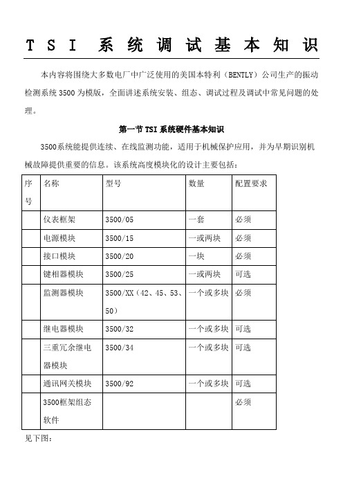
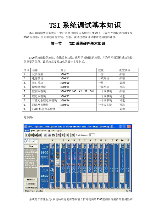
第一节 TSI系统硬件基本知识3500系统能提供连续、在线监测功能,适用于机械保护应用,并为早期识别机械故障提供重要的信息。
该系统高度模块化的设计主要包括:见下图:系统的工作流程是:从现场取得的传感器输入信号提供给3500监测器框架内的监测器和键相位通道,数据被采集后,与报警点比较并从监测器框架送到一个地方或多个地方处理。
3500框架中模件的共同特征是带电插拔和内部、外部接线端子。
任何主模件(安装在3500框架前端)能够在系统供电状态中拆除和更换而不影响不相关模块的工作,如果框架有两个电源,插拔其中一块电源不会影响3500框架的工作。
外部端子使用多芯电缆(每个模块一根线)把输入\输出模块与终端连接起来,这些终端设备使得在紧密空间内把多条线与框架连接起来变的非常容易,内部端子则用于把传感器与输入\输出模块直接连接起来。
外部端子块一般不能与内部端子输入/输出模块一起使用。
1、3500/05系统框架3500框架用于安装所有的监测器模块和框架电源。
它为3500各个框架之间的互相通讯提供背板通讯,并为每个模块提供所要求的电源。
3500框架有两种尺寸:1 全尺寸框架——19英寸EIA框架,有14个可用模块插槽2 迷你型框架——12英寸框架,有7个可用模块插槽电源和框架接口模块必须安装于最左边的两个插槽中。
其余14个框架位置(对与迷你型框架来说是其余7个位置)可以安装任何模块。
2、3500/15电源模块3500 电源是半高度模块,必须安装在框架左边特殊设计的槽口内。
3500 框架可装有一个或两个电源(交流或直流的任意组合)。
其中任何一个电源都可给整个框架供电。
如果安装两个电源,第二个电源可做为第一个电源的备份。
当安装两个电源时,上边的电源作为主电源,下边的电源作为备用电源,只要装有一个电源,拆除或安装第二个电源模块将不影响框架的运行。
本特利-3500
3500/45M(续)
继电器模块:3500/32
4/16通道继电器模块是一个全高模块,可提供4或 16个继电器的输出量。此模块的每个输出都可以独
立编程,以执行所需要的逻辑表决。
每个应用在此继电器模块上的继电器,都具有
“报警驱动逻辑”。该报警驱动逻辑可用“与门” 和“或门”逻辑编程,并可利用框架中的任何监测 器通道或任何监测器通道的组合所提供的报警输入。
径向振动
轴向位移 差胀 偏心
3500/42M(续)
①指示灯描述: OK:指示检测器I/O模块运行正常; TX/RX:接收和发送信号的速率闪动OK; BYPASS(旁路):指示该监测器的某些功 能被暂时抑制 ②传感器缓冲输出 ③位移/速度加速度带内部端子的I/O模块
3500/42M(续)---- 报警点设置
支持以下三种供电方式: 1、交流电源(175~264Vac或85~132Vac) 2、高压直流电源(88~140Vdc) 3、低压直流电源(20~30Vdc)
3500/22M框架接口模块 --------瞬态数据接口模块
3500瞬态数据接口(TDI)是3500监测系统和System机
械管理软件之间的接口。
本特利----3500
系统概述:
系统提供连续、在线监测功能,适用于机械保护应用。 此系统能够通过多种传感器采集数据,此硬件平台是专门为 帮助管理关键设备而设计和制造的,可为各类工厂人员提供 机械信息。
鉴于本厂动力站,此系统主要用于监测汽轮机的轴瓦 振动、轴位移、胀差及膨胀,并对位移、胀差及轴振进行报 警设置进而做出相关跳车逻辑输出。
继电器模块:3500/32
①发光二级管,指示继电器通道 工作的情况
②用来把继电器触点联到外部设 备的终端
本特利中文手册最新版3500-20
本特利内华达资产状态监测
3500/20 框架接口模块
文件编号 285173-01 修订版 NC(10/09)
3500/20 框架接口模块操作与维护手册
版权所有 2009 本特利内华达
保留所有权力
本手册内容如有更改,恕不另行通知。
以下为引用的其他法人实体的商标。
Telfon®是杜邦的注册商标。 Velostat®是3M公司的商标。
6 故障查找................................................................................................................ 52 6.1 校验................................................................................................................ 52 6.2 发光二极管LED故障状态................................................................................ 52 6.3 系统事件列表消息 .......................................................................................... 53 6.4 报警事件列表消息 .......................................................................................... 71
3.2 开关................................................................................................................ 19 3.2.1 软件开关 ................................................................................................. 19 3.2.2 硬件开关 ................................................................................................. 21
本特利3500中文说明书
本特利3500中文说明书TSI系统调试基本知识本内容将围绕大多数电厂中广泛使用的美国本特利(BENTLY)公司生产的振动检测系统3500为模版,全面讲述系统安装、组态、调试过程及调试中常见问题的处理。
第一节 TSI系统硬件基本知识3500系统能提供连续、在线监测功能,适用于机械保护应用,并为早期识别机械故障提供重要的信息。
该系统高度模块化的设计主要包括:序号名称型号数量配置要求1.仪表框架3500/05 一套必须2.电源模块3500/15 一或两块必须3.接口模块3500/20 一块必须4.键相器模块3500/25 一或两块可选5.监测器模块3500/XX(42、45、53、50)一个或多块必须6.继电器模块3500/32 一个或多块可选7.三重冗余继电器模块3500/34 一个或多块可选8.通讯网关模块3500/92 一个或多块可选9.3500 框架组态软件必须见下图:系统的工作流程是:从现场取得的传感器输入信号提供给3500监测器框架内的监测器和键相位通道,数据被采集后,与报警点比较并从监测器框架送到一个地方或多个地方处理。
3500框架中模件的共同特征是带电插拔和内部、外部接线端子。
任何主模件(安装在3500框架前端)能够在系统供电状态中拆除和更换而不影响不相关模块的工作,如果框架有两个电源,插拔其中一块电源不会影响3500框架的工作。
外部端子使用多芯电缆(每个模块一根线)把输入\输出模块与终端连接起来,这些终端设备使得在紧密空间内把多条线与框架连接起来变的非常容易,内部端子则用于把传感器与输入\输出模块直接连接起来。
外部端子块一般不能与内部端子输入/输出模块一起使用。
1、3500/05系统框架3500框架用于安装所有的监测器模块和框架电源。
它为3500各个框架之间的互相通讯提供背板通讯,并为每个模块提供所要求的电源。
3500框架有两种尺寸:1 全尺寸框架——19英寸EIA框架,有14个可用模块插槽2 迷你型框架——12英寸框架,有7个可用模块插槽电源和框架接口模块必须安装于最左边的两个插槽中。
本特利3500中文说明介绍模板之欧阳歌谷创编
TSI系统调试基本知识欧阳歌谷(2021.02.01)本内容将围绕大多数电厂中广泛使用的美国本特利(BENTLY)公司生产的振动检测系统3500为模版,全面讲述系统安装、组态、调试过程及调试中常见问题的处理。
第一节 TSI系统硬件基本知识3500系统能提供连续、在线监测功能,适用于机械保护应用,并为早期识别机械故障提供重要的信息。
该系统高度模块化见下图:系统的工作流程是:从现场取得的传感器输入信号提供给3500监测器框架内的监测器和键相位通道,数据被采集后,与报警点比较并从监测器框架送到一个地方或多个地方处理。
3500框架中模件的共同特征是带电插拔和内部、外部接线端子。
任何主模件(安装在3500框架前端)能够在系统供电状态中拆除和更换而不影响不相关模块的工作,如果框架有两个电源,插拔其中一块电源不会影响3500框架的工作。
外部端子使用多芯电缆(每个模块一根线)把输入\输出模块与终端连接起来,这些终端设备使得在紧密空间内把多条线与框架连接起来变的非常容易,内部端子则用于把传感器与输入\输出模块直接连接起来。
外部端子块一般不能与内部端子输入/输出模块一起使用。
1、3500/05系统框架3500框架用于安装所有的监测器模块和框架电源。
它为3500各个框架之间的互相通讯提供背板通讯,并为每个模块提供所要求的电源。
3500框架有两种尺寸:1 全尺寸框架——19英寸EIA框架,有14个可用模块插槽2 迷你型框架——12英寸框架,有7个可用模块插槽电源和框架接口模块必须安装于最左边的两个插槽中。
其余14个框架位置(对与迷你型框架来说是其余7个位置)可以安装任何模块。
2、3500/15电源模块3500 电源是半高度模块,必须安装在框架左边特殊设计的槽口内。
3500 框架可装有一个或两个电源(交流或直流的任意组合)。
其中任何一个电源都可给整个框架供电。
如果安装两个电源,第二个电源可做为第一个电源的备份。
当安装两个电源时,上边的电源作为主电源,下边的电源作为备用电源,只要装有一个电源,拆除或安装第二个电源模块将不影响框架的运行。
- 1、下载文档前请自行甄别文档内容的完整性,平台不提供额外的编辑、内容补充、找答案等附加服务。
- 2、"仅部分预览"的文档,不可在线预览部分如存在完整性等问题,可反馈申请退款(可完整预览的文档不适用该条件!)。
- 3、如文档侵犯您的权益,请联系客服反馈,我们会尽快为您处理(人工客服工作时间:9:00-18:30)。
此文档下载后即可编辑TSI系统调试基本知识本内容将围绕大多数电厂中广泛使用的美国本特利(BENTLY)公司生产的振动检测系统3500为模版,全面讲述系统安装、组态、调试过程及调试中常见问题的处理。
第一节TSI系统硬件基本知识3500系统能提供连续、在线监测功能,适用于机械保护应用,并为早期识别机械故障提供重要的信息。
该系统高度模块化的设计主要包括:见下图:系统的工作流程是:从现场取得的传感器输入信号提供给3500监测器框架内的监测器和键相位通道,数据被采集后,与报警点比较并从监测器框架送到一个地方或多个地方处理。
3500框架中模件的共同特征是带电插拔和内部、外部接线端子。
任何主模件(安装在3500框架前端)能够在系统供电状态中拆除和更换而不影响不相关模块的工作,如果框架有两个电源,插拔其中一块电源不会影响3500框架的工作。
外部端子使用多芯电缆(每个模块一根线)把输入\输出模块与终端连接起来,这些终端设备使得在紧密空间内把多条线与框架连接起来变的非常容易,内部端子则用于把传感器与输入\输出模块直接连接起来。
外部端子块一般不能与内部端子输入/输出模块一起使用。
1、3500/05系统框架3500框架用于安装所有的监测器模块和框架电源。
它为3500各个框架之间的互相通讯提供背板通讯,并为每个模块提供所要求的电源。
3500框架有两种尺寸:1 全尺寸框架——19英寸EIA框架,有14个可用模块插槽2 迷你型框架——12英寸框架,有7个可用模块插槽电源和框架接口模块必须安装于最左边的两个插槽中。
其余14个框架位置(对与迷你型框架来说是其余7个位置)可以安装任何模块。
2、3500/15电源模块3500 电源是半高度模块,必须安装在框架左边特殊设计的槽口内。
3500 框架可装有一个或两个电源(交流或直流的任意组合)。
其中任何一个电源都可给整个框架供电。
如果安装两个电源,第二个电源可做为第一个电源的备份。
当安装两个电源时,上边的电源作为主电源,下边的电源作为备用电源,只要装有一个电源,拆除或安装第二个电源模块将不影响框架的运行。
3500 电源能接受大范围的输入电压,并可把该输入电压转换成其它3500 模块能接受的电压。
对于3500 机械保护系统,有以下三种电源:1.交流电源2.高压直流电源3.低压直流电源输入电源选项:175 到264 Vac rms: (247 到373 Vac, pk),47 到63 Hz。
该选项使用交流电源且为高电压(通常220V)交流电源输入模块(PIM)。
安装版本R 以前的交流电源输入模块(PIM)和/或版本M 以前的电源模块要求电压输入:175 到250 Vac rms。
85 到132 Vac rms: (120 到188 Vac, pk), 47 到63 Hz。
该选项使用交流电源并且是低电压(通常110V)交流电源输入模块(PIM)。
安装版本R 以前的交流电源输入模块(PIM)和/或版本M 以前的电源模块要求电压输入:85 到125 Vac rms。
88 到140 Vdc: 该选项使用直流电源,并且是高电压直流电源输入模块(PIM)。
20 到30 Vdc: 该选项是低压直流供电,是低压直流供电模块(PIM)。
超限保护:对于所有电源类型,低电压不会损坏电源或PIM。
一个超范围电压将使PIM 上的保险丝开路。
满框架电流值:175 到254Vac 输入: 2.3 A rms (最大)。
85 到132 Vac 输入: 4.5 A rms (最大)。
88 到140 Vdc 输入: 2.5 A (最大)。
20 到30 Vdc 输入: 10.0 A (最大)。
输出:前面板发光二极管电源OK LED: 当电源工作正常时,灯亮。
单点接地线连接:为避免接地回路,系统必须提供一单点接地,电源输入模块为你提供了一个开关,来区别控制系统在哪儿接地。
如果装了两个电源,那么两个开关需要调到同一位置。
电源输入模块出厂时,开关调到关(CLOSED);接地系统通过末端(END)引到端子连接器上,如果系统在另一个地方接地,比如用外部安保器,需把开关调到(OPENED)。
下图演示了如何把开关跳到(OPENED)位置。
1.从端子连接器上拆除导线保护罩;2.拆下边上的十字槽螺钉,该螺钉用来固定电源输入模块的金属罩片;3.松开固定外壳地线夹子的两个螺钉,该螺钉位于端子连接器下,拆下外壳的地线夹子;4.拆下金属罩片底部的薄金属片,端子连接器滑过金属罩片。
5.把开关推向开(OPENED)位置;6.把金属罩片和外壳地线夹子在电源输入模块上复位。
3、3500/20框架接口模块框架接口模块(RIM)是3500框架的基本接口。
它支持本特利内华达用于框架组态并调出机组中信息的专有协议。
框架接口模块必须放在框架中的第一个槽位(紧靠电源的位置)。
RIM 可以与兼容的本特利内华达通讯处理器,如TDXnet、TDIX 和DDIX 等连接。
虽然RIM 为整个框架提供某些通用功能,但它并不是重要监测路径中的一部分,对整个监测系统的正确和正常运行没有影响。
每个框架需要一个框架接口模块。
其前面板上有RS-232 串行接口,可以与主机连接进行数据采集和框架组态,波特率最大38.4K,电缆长度要求最长30m。
后面的I/O (输入/输出)模块上有RS-232/RS-422 串行接口,同样可以与主机连接进行数据采集和框架组态,最大波特率38.4K,电缆长度:RS232为最长30m,RS422为最长1200m。
RS422接口还能使使多台3500框架以菊花链连接同3500 主机软件进行通讯。
连接计算机或上一个框架连接下一个框架前面板上各LED(发光二极管)含义:OK LED: 当框架接口模块操作正常时闪亮;TX/RX LED: 当RIM 与3500 框架中的其它模块相互通讯时闪亮;TM LED: 当3500 框架处于报警倍增状态时闪亮;CONFIG OK LED: 当3500 框架的组态正确时闪亮。
前面板各硬件开关作用:框架复位按钮: 清除锁定的报警和延时正常通道(Timed OK)失败,同输入/输出模块上的“框架复位”触点有相同的功能。
地址开关: 用来设置框架地址,共有63 个可选地址。
组态钥匙锁: 是用来设定3500 框架处于"RUN"(“运行”)模式或"PROGRAM"(“编程”)模式。
RUN 模式允许框架正常操作并且锁定任何组态变化。
PROGRAM 模式允许框架正常运行并且允许对框架进行远程或本地组态。
钥匙键可以在框架中的两个位置之间任意转还,允许开关保持在RUN 或PROGRAM 位置。
锁定至RUN 方式可以防止任何非授权的框架组态。
锁定至PROGRAM方式可以在任何时间对框架进行远程组态。
1)L ED:显示模块运行状态;2)硬件开关;3)组态端口:使用使用RS-232 协议,从框架中组态或调出机械数据;4) 框架接口I/O 模块:使用RS-232 和RS-422 通讯协议以菊花链形式连接或组态框架;5) 数据管理者系统I/O 模块: 连接两个本特利内华通讯处理器到3500 框架。
4、3500/22瞬态数据接口3500瞬态数据接口(TDI)是3500监测系统和本特利内华达System 1TM 机械管理软件之间的接口。
TDI结合了3500/20框架接口模块(RIM)和通讯处理器,如TDXnet的功能。
TDI运行在3500框架的RIM插槽中,与M系列监测器(3500/40M、3500/42M等)配合使用,连续采集稳态和瞬态波形数据,并通过以太网将数据传送到主计算机软件。
TDI具有标准的静态数据采集,但是采用可选的通道使能磁盘,也可采集瞬态或动态数据。
TDI与以前的通讯处理器相比,除了将通讯处理器的功能集成到3500框架以外,还有其它几方面的改进。
TDI为全部框架提供通用功能,但并不是关键监测通道的组成部分,不影响整个监测系统的正确和常规运行。
每个框架要求一个TDI 或RIM。
TDI只占用框架中的一个槽位,必须位于第一个插槽中(紧邻电源模块)。
对于三重模块冗余(TMR)应用,3500系统要求TMR形式的TDI。
除了所有标准TDI的功能,TMR TDI还具有“监测器通道比较功能”。
通过选择监测器选项的安装功能,3500TMR组态执行监测表决功能。
采用这种方式,TMR TDI连续比较三个冗余监测器的输出。
如果TMR TDI检测出其中一个监测器的输出信息与其它两个监测器不相等(在组态的百分比之内),它就会向监测器发出错误指示,并在系统事件列表中加入一个事件。
模件前面板的LED发光二极管的用途和各硬件转换开关与3500/20的相同,只是它的地址选择开关有127个地址可选。
背面板的接口如下图所示:1)主模块2)10/100 Base T以太网输入/输出模块,RJ-45(电话插座类型)用于10Base-T/100Base-TX以太网电缆,电缆长度最大100m;3)100 Base FX 以太网输入/输出模块,MT-RJ光纤接头,100Base-FX电缆,最大400米(1312英尺)多模光纤电缆;4)发光二极管:指示模块的运行状态5)硬件转换开关6)组态端口:采用RS-232协议组态或检索机器数据7)O K继电器:指示框架的OK状态8)光纤以太网端口:用于组态和数据采集9)R J45以太网端口:用于组态和数据采集10)系统触点5、3500/25键相器模块3500/25 改进的键相器模块是一个半高度,2 通道模块,用来为3500 框架中的监视器模块提供键相位信号。
此模块接收来自电涡流传感器或电磁式传感器的输入信号,并转换此信号为数字键相位信号,该数字信号可指示何时转轴上的键相位标记通过键相位探头。
每个键相模块有2个输入通道,3500 机械保护系统可安装2个键相器模块,接收4个键相位信号。
注: 键相位信号是来自旋转轴或齿轮的每转一次或每转多次的脉冲信号,提供精确的时间测量。
允许3500 监测器模块和外部故障诊断设备用来测量诸如1X 幅值和相位等向量参数。
每个键相器模块可接收2 个来自涡流传感器或电磁传感器的信号。
输入信号范围为-0.8V到-21.0V(非绝缘I/O 模块)和+5V到-11V(绝缘I/O 模块)。
模块内可限幅,使信号不得超过此范围。
无源电磁传感器要求轴转速大于200rpm(3.3Hz)。
在框架前面板上,通过同轴接头,有2 个缓冲键相位输出信号。
2 个缓冲键相位输出同样可在框架背面,通过欧式接头得到。
前面板发光二极管OK 指示灯: 可指示在键相器模块内检测到一个故障。
TX/RX 指示灯: 当键相器模块与框架接口模块(RIM)进行通讯时,发出指示。
下图所示为键相模块前视图和几种不同类型I/O模块的后视图。