RBU100H能量回馈单元说明书
万川达变频器V8 简易说明书
使用须知首先感谢您选用本系列矢量控制变频器!本系列变频器是一款通用高性能电流矢量变频器,可实现异步电机控制,功能强大。
可用于纺织、造纸、拉丝、旋切、机床、陶瓷、包装、食品、风机、水泵及各种自动化生产设备的驱动上。
禁止使用在武器、载人设备及高精度医疗设备上。
本说明书介绍了本系列变频器的功能特性以及使用方法,包括产品选型、参数设置、运行调试、维护检查等,请在使用前,请务必认真阅读本说明书。
另外,请在理解产品的安全注意事项后再使用该产品。
安全信息及注意事项安全定义:在本手册中,安全注意事项分以下两类:危险错误使用时,会引起危险发生,可能导致人身伤亡。
注意错误使用时,会引起危险发生,可能导致人身伤害或设备损坏。
请用户在安装、调试和维修本系统时,仔细阅读本章,务必按照本章内容所要求的安全注意事项进行操作。
如出现因违规操作而造成的任何伤害和损失均与本公司无关。
1.1安全事项:1.1.1安装前:1.1.2安装时:1.1.3配线时:1.1.4上电前:1.1.5上电后:1.1.6运行中:1.1.7保养时:1.2注意事项1.2.1电机绝缘检查电机在首次使用、长时间放置后的再使用之前及定期检查时,应做电机绝缘检查,防止因电机绕组的绝缘失效而损坏变频器。
绝缘检查时一定要将电机连线从变频器分开,建议采用500V 电压型兆欧表,应保证测得绝缘电阻不小于5MΩ。
1.2.2电机的热保护若选用电机与变频器额定容量不匹配时,特别是变频器额定功率大于电机额定功率时,务必调整变频器内电机保护相关参数值或在电机前加装热继电器以对电机保护。
1.2.3工频以上运行本变频器可提供0Hz~3200Hz 的输出频率。
若客户需在50Hz 以上运行时,请考虑机械装置的承受力。
1.2.4机械装置的振动变频器在一些输出频率处,可能会遇到负载装置的机械共振点,可通过设置变频器内跳跃频率参数来避开。
1.2.5关于电动机发热及燥声因变频器输出电压是PWM 波,含有一定的谐波,因此电机的温升、噪声和振动同工频运行相比会略有增加。
汇川技术 MD600系列 简易型变频器 手册包 A00

前言资料简介本产品是一款简易型通用变频器,具备小体积、高耐环境能力、简单易用、可靠、增效、节能等特点,主要用于控制和调节三相交流异步机转速,可用于硅晶、锂电、木工、物流、食品饮料、线缆、机床、简易风机泵类负载的驱动。
本手册介绍产品的选型、机械设计、电气设计、安装、通信、调试、功能应用、故障码、功能码、以及产品符合认证及标准等详细内容。
更多资料版本变更记录关于手册获取本手册不随产品发货,如需获取电子版PDF文件,可以通过以下方式获取:●登录汇川技术官方网站( ),“服务与支持-资料下载”,搜索关键字并下载。
●使用手机扫产品机身二维码,获取产品配套手册。
保修声明正常使用情况下,产品发生故障或损坏,汇川技术提供保修期内的保修服务(产品保修期请详见订货单)。
超过保修期,将收取维修费用。
保修期内,以下情况造成的产品损坏,将收取维修费用。
●不按手册中的规定操作本产品,造成的产品损坏。
●火灾、水灾、电压异常,造成的产品损坏。
●将本产品用于非正常功能,造成的产品损坏。
●超出产品规定的使用范围,造成的产品损坏。
●不可抗力(自然灾害、地震、雷击)因素引起的产品二次损坏。
有关服务费用按照厂家统一标准计算,如有契约,以契约优先的原则处理。
前言前言详细保修说明请参见《产品保修卡》。
安全注意事项安全注意事项安全声明●本章对正确使用本产品所需关注的安全注意事项进行说明。
在使用本产品之前,请先阅读产品手册并正确理解安全注意事项的相关信息。
如果不遵守安全注意事项中约定的事项,可能导致人员死亡、重伤,或设备损坏。
●手册中的“危险”、“警告”和“注意”事项,并不代表所应遵守的所有安全事项,只作为所有安全注意事项的补充。
●本产品应在符合设计规格要求的环境下使用,否则可能造成故障,因未遵守相关规定引发的功能异常或部件损坏等不在产品质量保证范围之内。
●因未遵守本手册的内容、违规操作产品引发的人身安全事故、财产损失等,汇川技术将不承担任何法律责任。
制动单元的使用手册

制动电阻 数量
1
1 2 并联 2 并联 3 并联 3 并联 3 并联 5 并联 5 并联
1 2 并联 2 并联 2 并联 3 并联 3 并联 3 并联 5 并联 5 并联
1
1 2 并联 2 并联 3 并联 3 并联 3 并联 5 并联 5 并联
1 2 并联 2 并联 2 并联 3 并联 3 并联 3 并联 5 并联 5 并联
第二部分:制动电阻器、制动单元的接线
制动电阻器的连接
使用制动电阻器单元时的接线示例如下所示。 CIMR-G7B20P4 ~ -G7B2015 型(200 V 级 0.4 ~ 15 kW), CIMR-G7B40P4 ~ -G7B4015 型(400 V 级 0.4 ~ 15 kW)的连接示例
制动电阻过热时,过热接点动作,切断变频器电源的顺控回路,避免电阻过热着火。
2000 W/70Ω
19.2Ω
4022 4030
CDBR4030
2000 W/70Ω 2500 W/65Ω
19.2Ω 19.2Ω
4037 4045
CDBR4045
2500 W/65Ω 2500 W/65Ω
12.8Ω 12.8Ω
注电阻规格共 4 类:
① 1000W/72Ω ② 1500 W/70Ω ③ 2000 W/70Ω ④ 2500 W/65Ω
1500 W/70Ω 1000 W/72Ω
32Ω 20Ω
4015
1000 W/72Ω
20Ω
G7
4018
1500 W/70Ω
19.2Ω
4022 CDBR4030
1500 W/70Ω
19.2Ω
4030
2500 W/65Ω
19.2Ω
调速器说明书1.2版本

安全注意事项安全标记的说明:危险:错误使用,可能会导致火灾、人身严重伤害,甚至死亡。
注意:错误使用,可能会导致人身中等程度的伤害或轻伤,以及发生设备损坏。
⏹用途危险●本系列调速器用于控制三相电动机的变速运行,不能用于单相电动机或其它用途,否则可能引起调速器故障或火灾。
●本系列调速器不能简单地应用于医疗装置等直接与人身安全有关的场合。
●本系列调速器是在严格的质量管理体系下生产的,如果调速器的故障可能会导致重大事故或损失,则需要设置冗余或旁路等安全措施,以防万一。
⏹到货检验注意●若发现调速器受损或缺少零部件则不可安装,否则可能发生事故。
⏹安装注意●搬运、安装时,请托住产品底部,不能只拿住外壳,以防砸伤脚或摔坏调速器。
●调速器要安装于金属等阻燃物上,远离易燃物体,远离热源。
●安装作业时切勿将钻孔残余物落入调速器内部,否则可能引起调速器故障。
●调速器安装于柜内时,电控柜应配置风扇、通风口,柜内应构建有利于散热的风道。
⏹接线危险●必须由合格的电气工程人员进行接线工作,否则有触电或损坏调速器的危险。
●接线前需确认电源处于断开状态,否则可能有触电或火灾的危险。
●接地端子PE要可靠接地,否则调速器外壳有带电的危险。
●请勿触摸主回路端子,调速器主回路端子接线不要与外壳接触,否则有触电的危险。
●制动电阻器的连接端子是⊕2/B1、B2。
请勿连接除此以外的端子,否则可能引起火灾。
●调速器整机的漏电流大于3.5mA,漏电流的具体数值由使用条件决定,为保证安全,调速器和电机必须接地。
⏹接线注意●三相电源不能接到输出端子U/T1、V/T2、W/T3,否则将造成调速器损坏。
●绝对禁止在调速器的输出端连接电容或相位超前的LC/RC噪声滤波器,否则将导致调速器内部器件损坏。
●请确认电源相数、额定电压是否与产品的铭牌相符,否则可能造成调速器损坏。
●不能对调速器进行耐压测试,否则可能造成调速器损坏。
●调速器的主回路端子配线和控制回路端子配线应分开布线或垂直交叉,否则将造成控制信号受干扰。
蓝海华腾变频器说明书

蓝海华腾变频器说明书V5- H系列变频器深圳市蓝海华腾技术股份有限公司V5- H 系列变频器是高性能矢量控制型变频器。
产品采用了与目前国际最领先技术完全同步的无速度传感器矢量控制技术,不仅具有与国际高端变频器同样优异的控制性能,同时还结合中国的应用特点,进一步强化了产品的可靠性和环境的适应性以及客户化和行业化的设计,能够更好地满足各种传动应用的需求。
产品优点:■高性能的开环矢量控制技术;■超强的负载能力,在任意加减速时间和任意冲击负载条件下,变频器稳定无跳闸运行;■提供独立的高速脉冲输入和输出端口,可实现高速脉冲级联功能;■精确的速度辨识和转子磁链定向,在0.25Hz 负载突变时转矩也能快速地响应和稳定运行;■高精度的电流检测和保护,采用高精度的霍尔进行输出电流的检测、满足软硬件的快速实时控制和保护要求,保证了整机的性能和可靠性。
典型行业:如印刷包装、石油化工、纺织、线缆机械、机床设备、食品包装、电动汽车、洗涤设备、塑料机械、金属制品设备、离心机及要求开环矢量的应用场合。
如长庆油田、辽河油田、胜利油田、奥力通起重机、开山压缩机、德曼压缩机、中铁桥梁、江苏海狮。
第一章V5-H 系列变频器介绍 (1)1.1产品型号说明 (1)1.2产品铭牌说明 (1)1.3产品系列. (2)1.4产品技术规格 (4)1.5产品各部分的名称 (5)1.6产品外形和安装尺寸及大概重量 (5)1.7操作面板的外形和安装尺寸 (7)1.8托板的外形和安装尺寸 (7)1.9制动电阻选型 (8)第二章变频器的安装 (9)2.1产品的安装环境 (9)2.2安装方向和空间 (9)2.3操作面板及盖板的拆卸和安装 (10)第三章变频器的配线 (13)3.1产品与外围器件的连接 (13)3.2主回路外围器件的说明 (14)3.3主回路外围器件选型 (14)3.4产品端子配置 (15)3.5主回路端子的功能 (16)3.6主回路配线注意事项 (17)3.7端子配线. (19)3.8控制回路端子功能 (20)3.9控制板示意图 (23)3.10控制回路外围器件选型 (23)3.11跳线功能说明 (23)第四章操作面板使用说明 (24)4.1操作面板介绍 (24)4.2指示灯说明. (24)4.3操作面板按键说明 (25)4.4菜单风格. (26)4.5密码操作. (30)4.6按键锁定及解锁 (31)4.7操作面板显示及按键操作 (31)4.8操作实例. (32)4.9首次运行. (33)第五章参数一览表 (35)5.1基本菜单功能码参数简表 (35)用户参数记录表 (49)5.3用户接线图 .......................................... 50 第六章参数详解 (51)6.1基本功能参数(P0 组) (51)6.2主辅给定参数(P1 组) (55)6.3按键及显示参数(P2 组) (58)6.4起停参数(P3 组) (60)6.5多段参数(P4 组) (62)6.6多功能输入参数(P5 组) (65)6.7模拟给定参数(P6 组) (70)6.8多功能输出参数(P7 组) (72)6.9过程PID 闭环参数(P8 组) (78)6.10电机参数(P9 组) (80)6.11控制参数(PA 组) (82)6.12增强功能参数(Pb 组) (87)6.13通讯参数(PC 组). (91)6.14矢量控制参数(Pd 组) (92)6.15故障记录参数(d0 组) (94)6.16产品识别参数(d1 组) (95)6.17运用显示参数(d2 组) (96)6.18用户定义功能码显隐区参数(A0 组)96 第七章故障诊断987.1故障及告警信息列表 (98)7.2故障诊断流程 (101)第八章日常保养及维护 (102)8.1 日常保养 (102)8.2定期维护 (103)8.3部件更换 (103)8.4绝缘测试 (103)附录A Modbus 通讯协议 (105)1支持协议 (105)2接口方式 (105)3协议格式 (105)4功能解释 (106)5变频器寄存器地址分布. (108)6CRC16 函数 (111)7Modbus 通讯控制举例 (111)8通讯网络的组建 (112)5.2附录B 各种控制方式设置流程 (113)1参数自整定的设置流程. (113)2过程开环的设置流程.. 错误!未定义书签。
RB600系列变频器说明书
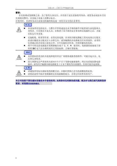
在安装调试变频器之前,为了您的人身安全,并有助于延长设备使用寿命,请您务必阅读本书安全规则及警告,以及贴于设备上的警示标志。
实际运行本设备。
●实施配线、检查等作业,必须关闭电源。
在本机印刷电路板上的充电指示灯熄灭前或在键盘显示熄灭后5分钟之内,请勿触摸机内电路板及任何零部件。
必须用仪表确认机内电容已放电完毕,方可实施机内作业,否则有触电的危险。
●绝不可将交流电源接至变频器输出端子U、V、W。
使用时,变频器的接地端子请依照IEC电气安全规程或其它类似标准,正确可靠接地。
●因人体静电会严重损坏内部MOSFET等静电敏感器件,所以未采取防静电措●请将此说明书放在变频器附近容易接触的地方,并将它们给所有的用户。
本公司保留不预先通知而修改本手册的权利;如果你有任何疑问或问题,请及时与我们或代理商保持联系,欢迎提出改进的建议。
1 产品简介…………………………………………………………1-1RB600 …………………………………………………………1-1储存运输………………………………………………………1-3开箱检查………………………………………………………1-32 技术规范…………………………………………………………2-1规格尺寸………………………………………………………2-1技术规范………………………………………………………2-33 安装配线…………………………………………………………3-1安装环境………………………………………………………3-1机械安装………………………………………………………3-1电气安装………………………………………………………3-24 操作运行…………………………………………………………4-1键盘操作………………………………………………………4-1参数修改………………………………………………………4-3参数监视………………………………………………………4-5初步运行………………………………………………………4-55 功能参数…………………………………………………………5-1功能简表………………………………………………………5-1详细功能………………………………………………………5-96 故障排除…………………………………………………………6-1故障查询………………………………………………………6-1故障代码………………………………………………………6-2异常处理………………………………………………………6-37 电磁兼容…………………………………………………………7-18 选件/附件………………………………………………………8-19 应用实例…………………………………………………………9-110保养维护…………………………………………………………10-1附录一:RS485串行通讯协议附录二:名词索引RB600是用于控制三相交流电动机的变频调速器。
摩尔晟UWTH1D_QB-100W(H F)R3系列100W隔离DC-DC转换器产品说明书

100W isolated DC-DC converterUltra-wide input and regulated single outputCB Report RoHSCSA62368EN62368BS EN62368IEC62368-1EN50155EN45545FEATURES●Ultra-wide12:1input voltage range:14-160VDC●High efficiency up to90%●Reinforced insulation,I/O isolation test voltage3k VAC●Operating ambient temperature range-40℃to+105℃●Active hold-up control,programmable inputunder-voltage control●Input reverse polarity protection,Inputunder-voltage protection,output over-voltage,over-current,short-circuit protection,over-temperature protection●Industry standard1/4-Brick package●Design to meet AREMA standards●Design to meet UL62368standardsThe UWTH1D_QB-100W(H/F)R3series is a high-performance product specifically designed for a variety of railway applications.The output power can reach at100W.It features wide input voltage of14-160VDC,which is compatible with nominal input type of24V,48V,72V,96V and110V.Meets EN50155standard for voltage fluctuations.The reinforced high insulation3000V AC ensures that the system can still be used safely in5000m high altitude applications.The allowable operating temperature is up to105°C.It integrates multiple protection functions to ensure the safety and high reliability of the system,with functions of remote control and compensation,output voltage adjustment,etc., which perfectly matches the requirements of line loss and special voltage in the application.It is widely used in vehicle-mounted switches, train control systems and associated equipment.Selection GuideCertification Part No.①Input Voltage(VDC)Output Full LoadEfficiency(%)③Min./Typ.Max.CapacitiveLoad(µF)Nominal(Range)Max.②Voltage(VDC)Current(mA)(Max./Min.)CSA/EN/BS EN/IECUWTH1D12QB-100W(H/F)R3110(14-160)160128330/088/907000 UWTH1D15QB-100W(H/F)R3156670/04500UWTH1D24QB-100W(H/F)R3244160/087/891800 UWTH1D28QB-100W(H/F)R3283570/01300UWTH1D48QB-100W(H/F)R3482080/088/901000 UWTH1D54QB-100W(H/F)R3541850/0820 Note:①Use“F/H”suffix for heat sink mounting.We recommend to choose modules with a heat sink for enhanced heat dissipation and applications with extreme temperature requirements;②Exceeding the maximum input voltage may cause permanent damage;③Efficiency is tested at nominal voltage and full load at+25℃ambient;④When UWTH1D_QB-100W(H/F)R3series products input voltage is14V~16.8V,the converter can work100ms at full load.Input SpecificationsItem Operating Conditions Min.Typ.Max.Unit Input Current(full load)24V input voltage24V,28V output--47894902mA12V,15V,48V,54V output--4735484536V input voltage24V,28V output--3157323012V,15V,48V,54V output--3121319348V input voltage24V,28V output--2341239612V,15V,48V,54V output--2315236972V input voltage24V,28V output--1561159712V,15V,48V,54V output--1543157896V input voltage24V,28V output--1184121112V,15V,48V,54V output--11711197Patent ProtectionInput Current (full load)110V input voltage 24V,28V output--10331057mA12V,15V,48V,54V output--10221045Reflected Ripple Current Nominal input voltage--150--Surge Voltage (1sec.max.)-0.7--200VDC Start-up Voltage ----14Start-up Current Nominal 48input voltage,full load----5000mA Start-up Time Nominal input voltage,constant resistance load--50100ms Input Filter LC filterHot PlugUnavailableNo-load Input Power Ctrl pin open or pulled high,DC-DC ON (14-160VDC)-- 1.2 2.0WIdle Input Power Ctrl pin pulled low to -Vin,DC-DC OFF (14-160VDC)--0.71.6Ctrl①Module on Ctrl pin open or pulled high (3.5-12VDC)Module offCtrl pin pulled low to -Vin (0-1.2VDC)Input Under-voltage Protection 1011--VDCUVLO②Operating temperature range,UVLO pin open,module off 10----Operating temperature range,UVLO pin connect to -Vin,module off60----Note:①The Ctrl pin voltage is referenced to input -Vin;②The UVLO pin voltage is referenced to input -Vin,please refer to Fig.9.Output SpecificationsItemOperating ConditionsMin.Typ.Max.Unit Voltage Accuracy Nominal input voltage,0%-100%load----±2%Linear Regulation Input voltage variation from low to high at full load --±0.2±0.5Load Regulation Nominal input voltage,10%-100%load --±0.5±1Transient Recovery Time 25%load step change @25℃----500µs Transient Response Deviation --±3±5%Temperature Coefficient Nominal output voltage,full load ----±0.03%/℃Ripple &Noise ①20MHz bandwidth,10%-100%load--150300mVp-p Trim 90--110%Vo Sense----105Over-temperature Protection Max.Case Temperature --115125℃Over-voltage Protection Input voltage range (14-160V)110--160%Vo Over-current Protection 105160260%IoShort-circuit ProtectionHiccup,continuous,self-recoveryNote:①The “Tip and barrel method”is used for ripple and noise test,for details please refer to Fig.3.General SpecificationsItem Operating Conditions Min.Typ.Max.UnitIsolationElectric Strength Test for 1minute with a leakage current of 5mA maxInput-output 3000----V AC Input-case 2500----Output-case2100----Insulation Resistance Input-output resistance at 500VDC 1000----M ΩIsolation Capacitance Input-output capacitance at 100KHz/0.1V--1100--pF Operating Temperature -40--105℃Storage Temperature -55--125Pin Soldering Resistance TemperatureSoldering spot is 1.5mm away from case for 10seconds ----300Storage Humidity Non-condensing 5--95%RH Switching Frequency PWM mode --175--KHz MTBF IEC 61709@25℃1000----k hours Cooling Test EN60068-2-1Dry Heat EN60068-2-2Damp HeatEN60068-2-30Shock and Vibration Test IEC/EN61373Class B Pollution Level PD3Fire&Smoke Compliance EN45545-2,HL3 Salt Mist Test EN60068-2-11,Ka Cyclic Damp Heat Test EN60068-2,Db variant2 Altitude①5000mLow Temperature Start-up andStorage Test EN60068-1,Ad and Ab Note:①When the altitude is above2000m,the product surface max.temperature must be below105℃.Mechanical SpecificationsCase Material Aluminum alloy case;Black plastic bottom,flame-retardant and heat-resistant(UL94V-0)Dimension Without heat sink57.90x36.80x12.70mm With H heat sink57.90x36.80x25.40mm With F heat sink62.00x56.00x14.50mmWeight Without heat sink79.5g(Typ.) With H heat sink109.5g(Typ.) With F heat sink99.5g(Typ.)Cooling Method Conduction cooling or forced air coolingFree air convection cooling with additional heat sink Electromagnetic Compatibility(EMC)(EN50121-3-2)Emissions CEEN50121-3-2EN55016-2-1150kHz-500kHz99dBuV(see Fig.6for recommended circuit)500kHz-30MHz93dBuV(see Fig.6for recommended circuit)EN55032EN55032-11150kHz-500kHz79dBuV(see Fig.6for recommended circuit)500kHz-30MHz73dBuV(see Fig.6for recommended circuit) RE CISPR16-2-330MHz-230MHz40dBuV/m at10m(see Fig.6for recommended circuit)230MHz-1GHz47dBuV/m at10m(see Fig.6for recommended circuit)1GHz-6GHz47dBuV/m at10m(see Fig.6for recommended circuit)Immunity ESD EN61000-4-2Contact±6kV/Air±8kV perf.Criteria A RS EN61000-4-380–800MHz20V/m800–1000MHz20V/m1400–2000MHz10V/m2000–2700MHz5V/m5100–6000MHz3V/mperf.Criteria A EFT EN61000-4-4±2kV5/50ns5kHz(see Fig.6for recommended circuit)perf.Criteria A Surge EN61000-4-5line to line±1kV(42Ω,0.5μF)line to ground±2kV(42Ω,0.5μF)(see Fig.6for recommended circuit)line to line±1kV(2Ω,18μF)line to ground±2kV(12Ω,9μF)(see Fig.6for recommended circuit)perf.Criteria A CS EN61000-4-60.15MHz-80MHz10V r.m.s perf.Criteria AElectromagnetic Compatibility(EMC)(AREMA)Emissions CECISPR16-2-1150kHz-500kHz79dBuV(see Fig.6for recommended circuit)CISPR16-1-2500kHz-30MHz73dBuV(see Fig.6for recommended circuit)RE CISPR16-2-330MHz-230MHz230MHz-1GHz40dBuV/m at10m(see Fig.6for recommended circuit)47dBuV/m at10m(see Fig.6for recommended circuit)Immunity ESD IEC61000-4-2Contact±6kV/Air±8kV perf.Criteria ARS IEC61000-4-380–1000MHz10V/m160–165MHz20V/m450–470MHz20V/m800–960MHz20V/m1400–2000MHz20V/m2100–2500MHz5V/mperf.Criteria AEFT IEC61000-4-4±2kV5/50ns5kHz(see Fig.6for recommended circuit)perf.Criteria A Surge IEC61000-4-5line to line±2kV(2Ω,18μF)line to ground±2kV(12Ω,9μF)(see Fig.6for recommended circuit)perf.Criteria A CS IEC61000-4-60.15MHz-80MHz10V r.m.s perf.Criteria AMS IEC61000-4-860Hz100A/m(see Fig.6for recommended circuit)perf.Criteria A 60Hz300A/m(see Fig.6for recommended circuit)Typical Performance CurvesRemote Sense Application1.Remote Sense Connection if not usedFig.1Notes:(1)If the sense function is not used for remote regulation the user must connect the+Sense to+Vo and-Sense to-Vo.(2)The connections between Sense lines and their respective power lines must be kept as short as possible,otherwise they may be picking up noise,interference and/or causing unstable operation of the power module.2.Remote Sense Connection used for CompensationFig.2Notes:(1)Using remote sense with long wires may cause unstable output,please contact technical support if long wires must be used.(2)PCB-tracks or cables/wires for Remote Sense must be kept as short as possible.Twisted pair or shielded pairs are suggested for remote compensation and must be kept as short as possible.(3)We recommend using adequate cross section for PCB-track layout and/or cables to connect the power supply module to the load in order to keep the voltage drop below0.3V and to make sure the power supply's output voltage remains within the specified range.(4)Note that large wire impedance may cause oscillation of the output voltage and/or increased ripple.Consult technical support or factory for further advice of sense operation.Design ReferenceAll the DC-DC converters of this series are tested before delivery using the recommended circuit shown in Fig.3.Fig.3CapacitorsvalueOutput voltageC0(µF)C1(µF)C2(µF) 12VDC100µF,voltage≥200V1µF,voltage≥1.2*Vo330µF,voltage≥1.2*Vo 15VDC24VDC28VDC48VDC54VDC2.Typical application1.Mornsun EMC circuit is recommended,otherwise please ensure that at least a100µF electrolytic capacitors is connected at the input in order to ensure adequate voltage surge suppression and protection.2.Output ripple can be further reduced by appropriately increasing the output capacitor values C3and/or by selecting capacitors with a low ESR(equivalent series resistance).Also make sure that the capacitance is not exceeding the specified max.capacitance load value of the product.3.The UVLO pin can adjust the point of input under-voltage protection by the external resistance RUVLO.Please refer to Fig.9for the value of RUVLO,if the pin is left open,the under-voltage protection point is11V.4.Ctrl current-mode logic recommended circuit design refer to fig.4.Fig.4Components Value Recommended Component R010K--C30.1µF voltage≥25VQ1Ic≥10mA voltage≥30V Note:S1pin open,DC-DC ON.3.Trim Function for Output Voltage Adjustment (open if unused)Fig.5Trim resistor connection (dashed line shows internal resistor network)Calculation formula of Trim resistance:322T R a R R *a =R :up Trim -- 2.5-Vo R *2.5=a 1311T *=R :down Trim R bR R b --5.2R *)5.2o V (=b 2-Note :a ,b:self-defined parameter ,round to the nearest hundredth R T [k Ω]:Resistance of Trim.Vo:Output voltage change.V ref [VDC]:Reference voltage.Vo Res 12(VDC)15(VDC)24(VDC)28(VDC)48(VDC)54(VDC)R1(K Ω)1114.3524.828.85461R2(K Ω) 2.87 2.87 2.87 2.87 2.94 2.94R3(K Ω)20.220.223.123.118.218.2Practical Example trim up -10%for 12V output:53.9=5.287.2*)5.28.10(=b -ΩK 113.51=2.2053.91111*53.9=R T --R T according to E24≈51k ΩPractical Example trim up +10%for 12V output:57.2=5.22.1311*5.2=a -ΩK 386.4=2.2057.287.287.2*57.2=R T --R T according to E24≈4.3k Ω4.EMC compliance circuit1.The anti-reverse connection circuit is composed of a circuit breaker and a diode D1.The withstand voltage of the diode D1mustbe greater than 250V;2.The EMC filter part is composed of modular circuits.Please refer to Figure 6for recommended circuits and parameters.Self-built circuits can also be used;3.Resistor RUVLO is used to adjust the input under-voltage protection point.Refer to Figure 9for the value.Fig.6Matching Power output voltageC omponents ValueC4C2C1CY4,CY5,CY6D112V 330µFVoltage ≥200V330µFVoltage ≥1.2*Vo1µFVoltage ≥1.2*Vo3300pF /400V AC Y1safety capacitor20AVoltage ≥200V15V 24V 560µFVoltage ≥200V28V 48V 54V BreakerThe Breaker value varies with different power modules and must be selected in accordance with the specified input current of the corresponding power converter,but not exceeding the filter specifications.Note:A ferrite core on the power lines and load lines can ensures a better EMI test margin.EMC FilterComponentsValue Recommended ComponentC60.1µF Voltage ≥630V C80.22µF Voltage ≥250V C9 2.2µF Voltage ≥250V LCM1≧2mH FL2D-A2-202LCM2≧4mH COMMON MODE,≧4mH,35m Ω,-40to +125℃Ø1.2mm×24Ts LDM10.47µH Shielding Inductive LDM2150µH Differential MODE,150uH ±35%,30m Ω,-40to +125℃Core T10*6*4,Ø0.5mm×25TsCY1,CY22200pF /400V AC Y1safety capacitor CY31000pF /400V ACY1safety capacitorMOV17D221KVaristorNote:The emc filter recommended to use MORNSUN P/N:FC-C08D.Surge standardComponentsValue Recommended Component line to line ±1KV (42Ω,0.5μF)line to ground ±2kV (42Ω,0.5μF)C0100µF Voltage ≥250VC10,C11----line to line ±1KV (2Ω,18μF)line to ground ±2kV (12Ω,9μF)C0,C10100µF Voltage ≥250VC11----line to line ±2KV (2Ω,18μF)line to ground ±2kV (12Ω,9μF)C0,C10,C11100µFVoltage ≥250V5.Hold-up time setup capacitorFig.7Recommended circuit and PCB layout for hold-up timeThe hold-up time capacitor CExt.Cap is used to hold the output when the input power off.Note:1.If there is no requirement for the hold-up time,no additional capacitor CExt.Cap is required;2.For the hold-up time of 10ms and 30ms,please refer to table blow;3.Vq is Start-up voltage.Po (W)100Vin (V)2436487296110V q (V)13.219.526.940.353.461.1C Ext.Cap (µF)△t:10ms470470470470470470△t:30ms1410141014101410141014106.Recommended circuit for multi-module parallel redundant designFig.8Note:1.The function of capacitor C1,C2is filtering.It is used for margin design and cannot be used to increase power;2.The diodes D2and D3are used to protect the power module.In actual use,the user can choose the parameters of the diode or MOSFET according to the output current;3.Because the output impedance of the two modules is different,the output power of each module cannot be guaranteed to be equal;Pload =P1+P2<Pmax (100W).7.UVLO Function and R UVLO ValuesThe products with an ultra-wide input voltage range,covering a variety of nominal input voltages.Set the input under-voltage point adjustable function for different input systems,connect a resistor between UVLO pin and -Vin,adjust the under-voltage point of the product by adjusting the resistor value.Fig.9UVLO values for various nominal input voltage and R UVLO tableNominal input voltage (V)2436487296110Starting Voltage (V)13.219.526.940.353.461.1Shutdown Voltage (V)11.216.723.334.846.353.1UVLO setup resistance (K Ω)open15056.118.35.61.5UVLO setup calculation100nF/50V/0805Calculation formula of R UVLO setup resistance :20-c-182c*182=R UVLO 6.45-V 1272.35=c shutdown Note:c:self-defined parameter.R UVLO (K Ω):UVLO setup resistance.V shutdown:UVLO shutdown voltage.8.For additional information please refer to DC-DC converter application notes on Dimensions and Recommended Layout(without heat sink)Note:1.For additional information on Product Packaging please refer to .Packaging bag number:58010113(UWTH1DxxQB-100WR3);58220017(UWTH1DxxQB-100WHR3);58200069(UWTH1DxxQB-100WFR3);2.The maximum capacitive load offered were tested at input voltage range and full load;3.Unless otherwise specified,data in this datasheet should be tested under the conditions of Ta=25℃,humidity<75%RH with nominal inputvoltage and rated load;4.All index testing methods in this datasheet are based on our company corporate standards;5.Product customization is available,please contact below email directly for specific needs;6.Products are related to laws and regulations:see"Features"and"EMC";7.Our products shall be classified according to ISO14001and related environmental laws and regulations,and shall be handled byqualified units.Mornsun Guangzhou Science&Tech nolo gy Co.,Ltd.Address:No.5,Kehui St.1,Kehui Development Center,Science Ave.,Guangzhou Science City,Huangpu District,Guangzhou,P.R.ChinaTel:86-20-38601850Fax:86-20-38601272E-mail:***************。
宝工 MT-2207-C指针型防误测三用电表 说明书

Ohms Zero Adjustor located at the right side of the panel. Adjust the meter pointer to the Zero mark on the right side of Ohm scale of the meter dial when the test leads are touched together. Mechanical Adjustor Screw: located right side below the center of the meter dial to set pointer to Zero mark at the left side of the scale. (-) Jack: Plug-in connector at the lower left on the panel for black, negative test lead. (+) Jack: Plug-in connector at the lower right on the panel for Red, positive test lead.
the highest range. 4. If meter indication is in the lower half of the scale and falls within the range
of a lower scale, reset selector switch to the lower range for greatest accuracy. 5. If the meter won’t work at all, check the fuse located on the PCB. If it’s blown, replace it. (See fuse replacement.) 6. Avoid placing the meter where extreme shock or continuous vibration is encountered and do not store in excessively hot or damp places. Although very rugged, the meter is a sensitive measuring device and should be handled carefully & properly. 7. Do not check resistance, transistor, diode, LED, or capacitance when live voltage or current input across the circuit. 8. When the meter is not in use, keep the selector switch to the “DC or AC voltage” range position, this provides direct short across meter movement for minimum needle bounce when transporting meter. 9. If you should accidentally apply excessive voltage or current on a certain range, disconnect the leads from the circuit as quickly as possible, check instrument operation on that range by applying peoper input. If the meter does not operate properly, check fuse. If it is blown replace it. (See fuse replacement.)