锐乐尔编码器说明书hn3806-ab-600n
GAX60R1312E10LB编码器说明书

GAS60,GAX60,GMS412,GMX425,GEX38系列编码器 源自BEN13测角度 测长度 测速度的多面手. 零二一:三九伍三六二一九* 内部绝对值码盘,机械齿轮组真多圈,全数字化计值。
* 国际标准Modbus RTU 输出,方便连接各种PLC 及上位机设备。
* 精芬机电软件设定,多用途、多功能,直接对应单圈多圈角度、多圈长度、转动平移速度测量。
* 多地址设定;通讯波特率设定,分辨率、方向设定。
* 外部置位线设定预设位置,安装方便,无需找零。
特性参数:工作电压:10~30Vdc 极性保护 消耗电流:< 110mA (24Vdc ) < 190mA (12Vdc ) 输出信号:国际标准Modbus 输出,符合GB/Z19582标准,可设定长度、角度、速度应用输出 分 辨 度:4096/圈 连续圈数: 1~4096圈BEN: 地址可设定,通讯波特率设定(9600~115200),可RS485信号连接PLC ,或转RS232或转USB 连接计算机,可jfsh 智能设定工作温度:-25~80℃ 编程时温度范围:0℃~70℃ 储存温度:-40~80℃ 防护等级:外壳IP67 转轴IP65 振动冲击:20g ,10~2000Hz ;100g ,6ms 允许转速:3400转/分 输出刷新周期:<1ms 连接电缆:1米屏蔽电缆径向侧出(其余形式可订货) 外形特征:金属外壳,密封双轴承结构(见外形尺寸附图) 信号调整: 可分辨率、方向设置;可预设位置,外部置位,例如外部置零以上老型号新型号是BE420SM58系列,沟通一伍零二一零二伍伍九八输出接口:(以产品说明书为准)外型尺寸:(单位mm )GMX9640夹紧法兰系列 L: 侧出为40 后出为59(其他型号尺寸询公司查询)。
海湾编码器说明书

海湾编码器说明书189******** 海湾电⼦编码器安装使⽤说明书⼀、概述GST-BMQ-2电⼦编码器(以下简称编码器)可对电⼦编码的探测器或模块进⾏地址码、灵敏度、设备类型等的读出和地址码、灵敏度的写⼊功能,还可以对⽕灾显⽰盘进⾏地址码、灯号及⼆次码的读出和写⼊。
⼆、特点1. 该编码器采⽤⼿握式结构,外形⼩巧,携带⽅便,操作简单;2. 该编码器可通过编码器后盖的总线接⼝,直接和总线型探测器旋接,进⾏编码等操作,更加⽅便,如图2所⽰(略);3. 可对公司⽣产的总线型探测器、模块等设备编码,可对ZF-GST8903⽕灾显⽰盘、JTY-HM-GST102线型光束感烟⽕灾探测器、JTY-HF-GST102线型光束感烟⽕灾探测器、隔爆点型可燃⽓体探测器等I2C接⼝设备编码;4. 四位段码式液晶显⽰,显⽰直观;5. 低功耗睡眠和⾃动关机功能;6. 电池⽋压指⽰功能三、技术特性1. 电源:1节9V叠式电池2. ⼯作电流≤8mA3. 待机电流≤100чA4. 使⽤环境:温度:-10℃~+50℃相对湿度≤95%,不凝露5. 尺⼨:164mm×64mm×37m m四、结构特征外形⽰意图如图1所⽰(略)1:电源开关 2:液晶屏3:总线插⼝ 4:⽕灾显⽰盘接⼝(I2C)5:复位键 6:固定螺丝7:电池盒后盖 8:铭牌9:JTY-GD-G3、JTY-ZCD-G3N探测器总线接⼝10:JTY-GM-GST9611、JTW-ZOM-GST9612型探测器总线接⼝11:电池盒后盖螺丝 12:保护盖其中各部分名称和功能说明如下:1. 电源开关:完成系统硬件开机和关机操作。
2. 液晶屏:显⽰有关探测器的⼀切信息和操作⼈员输⼊的相关信息,并且当电源⽋压时给出指⽰。
3. 总线插⼝:编码器通过总线插⼝与探测器或模块相连。
4. ⽕灾显⽰盘接⼝(I2C):编码器通过此接⼝与ZF-GST8903⽕灾显⽰盘或以I2C编程⽅式编码的探测器相连。
Baumer 磁敏感器编码器说明书
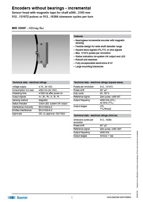
u b j e c t t o m o d i fi c a t i o n i n t e c h n i c a n d d e s i g n . E r r o r s a n d o m i s s i o n s e x c e p t e d .Features–Bearingless incremental encoder with magnetic sensing–Flexible design for wide shaft diameter range –Square-wave signals HTL/TTL or sine signals –Max. 131072 pulses per revolution–Status indication via system OK output and LED –Robust and wearless–Fully encapsulated electronics IP 67 –Large mounting tolerancesTechnical data - electrical ratings (square-wave)Pulses per revolution 512...131072Phase shift 90° ±2°Duty cycle 45...55 %Reference signal Zero pulse, width 90°Output frequency ≤500 kHz (HTL) ≤2 MHz (TTL)Output stagesHTLTTL/RS422MIR 3000F - HDmag flexTechnical data - electrical ratings (SinCos)Sinewave cycles per revolution 512...16384Phase shift 90° ±2°Reference signal Zero pulse, width 360°Output frequency ≤500 kHz Output stagesSinCos 1 VppTechnical data - electrical ratings Voltage supply 4.75...30 VDC Consumption w/o load ≤300 mA (24 VDC)Initializing time ≤1000 ms after power on Output signals A+, B+, R+, A-, B-, R-Sensing method MagneticStatus indicator Color-LED, system OK output Interference immunity EN 61000-6-2Emitted interference EN 61000-6-3ApprovalsCE, UL approval / E217823u b j e c t t o m o d i fi c a t i o n i n t e c h n i c a n d d e s i g n . E r r o r s a n d o m i s s i o n s e x c e p t e d .MIR 3000F - HDmag flexTechnical data - mechanical design Shaft typeø300...3183 mm (through hollow shaft)Dimensions (sensor head)165 x 25 x 93 mm Axial tolerance ±5 mm (belt to head)Radial tolerance1...3 mm (belt to head)Protection DIN EN 60529IP 67Operating speed≤1850 rpm (ø300 mm) ≤150 rpm (ø1500 mm) see diagram belowMaterialsHousing sensing head: aluminium alloyMagnetic belt: stainless steel (1.4104)Operating temperature -40...+85 °CResistanceIEC 60068-2-6Vibration 30 g, 10-2000 Hz IEC 60068-2-27 Shock 300 g, 6 msWeight approx.730 g (head), 120 g (belt/m), 17 g (lock)ConnectionFlange connector M23, 12-pin30507090110130150170S p e e d [r p m ]Shaft diameter [mm]190210230250270290310Speed dependent on the shaft diameteru b j e c t t o m o d i fi c a t i o n i n t e c h n i c a n d d e s i g n . E r r o r s a n d o m i s s i o n s e x c e p t e d .MIR 3000F - HDmag flexPart number MIR3000F-.....M..AOperating temperature A -40...+85 °CPulse number/sinewave cycles - see tableVoltage supply / output stagesQ 4.75...30 VDC, HTL (Vin = Vout), 6 channel F 4.75...30 VDC, TTL/RS422, 6 channel T 4.75...30 VDC, SinCos (1 Vpp), 6 channelConnectionM Flange connector M23, tangential 12-pin, male, CCWShaft diameter (mm)....0300 (3183)Other pulse numbers/sinewave cycles on request.Maximum sinewave cycles 16384 for SinCos output.AccessoriesConnectors and cables HEK 8Sensor cable for encoders11068549Mating connector M23, solder version, 12-pin, CWPulse number/sinewave cycles 512102450001638472020488192327681000409610000131072u b j e c t t o m o d i fi c a t i o n i n t e c h n i c a n d d e s i g n . E r r o r s a n d o m i s s i o n s e x c e p t e d .Terminal assignmentOutput signalsMIR 3000F - HDmag flexu b j e c t t o m o d i fi c a t i o n i n t e c h n i c a n d d e s i g n . E r r o r s a n d o m i s s i o n s e x c e p t e d .MIR 3000F - HDmag flexDimensions。
BRG编码器使用手册说明书
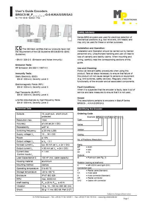
User‘s Guide EncodersBRGC5-W_P_ _ _-_ _-G-0-K/KA/S/SR/SA3Nr. 719 100 E • Edition 1702.The CE-Mark certifies that our products have met the requirement of the CE Guideline 89/336/EWG (EMC Guideline):- EN 61 326-2-3 (Emission and Noise Immunity)Emission Tests:RF Emission: EN 55011:1997+A1Immunity Tests:Static Electricity (ESD):EN 61 000-4-2, Severity Level 3Elektromagnetic Fields (RFI):EN 61 000-4-3, Severity Level 3Fast Transients (BURST):EN 61 000-4-4, Severity Level 4Line-fed disturbances by high-frequericy fields EN 61 000-4-6, Severity Level 3Series BRG encoders are used for electrical detection of mechanical positions (e.g. tool revolvers, drill heads) and may only be used for these or similar purposes.Installation and Operation:Installation and Operation should be carried out by trained personnel only. Unauthorized handling and use will Iead to loss of warranty and liability claims. When mounting and wiring, carefully read the corresponding sections of this guide.Use and Checking:Follow all relevant safety procedures when using this product. Take all steps necessary to ensure that failure of this product will not cause danger to persons or equipment (e.g. limit switches, safety devices). Regularly check the functionality of the encoder and all associated components.Fault Conditions:When lt is suspected that the encoder is faulty, take it out of service and take measures to ensure that lt is not used.Scope:This descriptions pertains to encoders in Balluff Series BRGC5-...-K/KA/S/SR/SA3. Safety AdvisoryTechnical DataOutputs 10, push-pull, short circuit protected Resolution max.1024Accuracy ±½ bit (at 24 V DC)Repeatability ±45° el.Switching frequency ≤ 25 kHz (LSB) Supply voltage V S 10 ... 30 V DC Ripple≤ 10% Output voltage V O ≥ U B - 3 VNo-load current I R typ. 50 mA (at V O = 24 V DC) Output current I O < 50 mA (at V O = 24 V DC)Current draw Control inputs I C < 1 mALoad Capacitance C 100 nF (incl. cable capacity)Housing material aluminium Mounting method clamps Operating temperature 0 to 60 °C Storage temperature -20 to +80 °C Enclosure IP 67 IEC 529RPM max. 6000/min shaft loading F AX ≤ 25 N; F RAD ≤ 40 N Vibration 10 g, 10...150 Hz (IEC 68: 2-6)Shock50 g/ 11 ms (IEC 68: Part 2-27)Identifying the EncoderOrdering CodeExample: BRGC5-WAP360-OP-G-0-SType Series Version CodingNo. of Positions (Resolution)Parity EP = even OP = odd 00= noOutputs G = Push-pull (see Fig. 3) Rotation (looking at shaft end)0 = left (CCW) and right (CW) Connection type K = Radial cable(Standard) KA = Axial cable S = Axial connector(Standard)SR = Radial connector SA3 = Cable with connectorUser‘s Guide EncodersBRGC5-W_P_ _ _-_ _-G-0-K/KA/S/SR/SA3Nr. 719 100 E • Edition 1702.Using the coupling:- Attach the encoder to the drive rigidly at one point only: either flange to flange or shaft to shaft. Use the couplings. - Be sure that the encoder shaft and the drive are an the same axis. Check the data sheet for the coupling to find the permissible axial or radial offset and the maximum angle error of the two shafts.- Be sure not to damage or bend the coupling excessively while installing and aligning it.- Tighten all mounting screws very carefully.Please note the following:- Never use force (e.g. hammer or blows) to install or align the encoder.- Do not exceed the bad tolerances given for the encoder shaft (see technical data).- Never step on the encoder, cord seal, or connector.BRG A3-...-K/KA-SA3Axial Offset Radial OffsetAngle ErrorBRG C5-...-KABRG C5-...-K BRG C5-...-S BRG C5-...-SRBRG C5-...-K-SA3Fig. 1: DimensionsNote the following:- Connect all cable according to the table at lower right.- Isolate all unused grounds (to avoid short circuit).- Make sure that self-wired connectors are sealed properly. Oil or water entering along the cable can enter the electronics area and destroy the unit.- The IP 67 rating can be assured only if your connections, especially in the case of short cables, meet the IP 67 specification also.- Do not route the BRG encoder cable parallel to AC lines, in order to avoid noise coupling.- Use shielded cable only, in order to avoid noise coupling.- Ground the shield on the control side only.- Plug or unplug the encoder connector only after power has been turned off.- Turn power on and off to the encoder and the input device at the same time only. Output Driver:At overload all outputs will be switched off. Switch off supply voltage and after the fault has been removed, turn power on.Fig. 3: Output circuittrack 1 to track 10+V0 VFig. 2: Cable/connector assembly for BRGC5-...-S/SRBRG C5-ST-...Connections BRGC5-...-K/KA/S/SR:Determine your BRG model and its resolution. The resolution is critical for the wiring.Pin Configuration: Solder side view of the connector Fig. 4: Connector for BRGC5-...-S/SRBKS-S55-00ca. 71Pin Configuration: Solder side view of the connectorFig. 5: Connector for BRGC5-...-SA3。
亨士乐编码器

(多圈),包括总线罩壳 ■ 可提供所有常见总线接口 ■ 在总线罩壳内装有完整的总线电
子电路 ■ 类型:Profibus DP、DeviceNet、
CAN、CANopen 和 Interbus ■ 选件:“tico” 显示器
“tico”显示器用于诊断和位置显示
北京西曼自动化技术有限公司
3
ACURO工业型: 快速和简易的安装
总线组网: 最多8个传感器可以与一个总线主站相 连。对于多轴应用来说,连线和控制成 本显著降低。
有关BiSS以及其实现的详细信息,请访 问 。
BiSS带来的好处: ■ 不需要采样电路等附加成本 ■ 提供很高的传输可靠性 ■ 是唯一用于实时控制的全数字
化、开放式电机反馈接口。
5 V, -5 % /+10 % 50 mA/100 mA 标准SSI或BiSS 时钟和数据/RS422 二进制或格雷码,通过Acuro soft参数化 13位 (SSI) 22位 (BiSS)
12位 正弦 - 余弦 1 Vpp 2,048 500 kHz ± 35´´ ± 7´´ PCB插头12极/14极 分辨率、代码类型、旋转感应、警告、 报警 – – 报警位(SSI 选项)、 警告位和报警位 (BiSS) –
工业型编码器用于印刷机、包装机、电 梯和风力发电站等多种应用中。
OCD编码器说明书

6,000 转/12,000 转(持续)
≤30g(半正弦, 11ms)
≤10g(半正弦, 16ms)
≤10g(10Hz…1,000Hz)
≈500g, ≈700g
轴向 200N, 径向 300N
≤3Ncm
同步法兰
夹紧法兰
6mm/10mm
10mm
10mm/20mm
20mm
盲孔轴 10mm ——
环境参数 工作温度 储存温度 湿度 防护等级(EN 60529) 壳体部分 主轴部分
CANL
5
2
粉
CAN 总线低电位
CANG
1
3
绿
CAN 总线地线
VCC
2
12
棕
电源正
GND
3
10
白
电源负
A﹡
-
5
蓝
A 相/SIN 正向输出
/A﹡
-
6
紫
A 相/SIN 负向输出
B﹡
-
8
灰/粉
B 相/COS 正向输出
/B﹡
-
9
红/蓝
B 相/COS 负向输出
Shielding
-
-
Shielding
附加增量式输出,差分 TTL 或差分 1Vpp SIN/COS 信号输出可选。
0x06090011
Sub‐index does not exist
0x06090032
Value of parameter written too low
0x06090031
Value of parameter written too high
0x06010002
At
0x06010001
KOYO 旋转光电编码器说明书

100N 50N 0.1N·m 以下
IP65:防尘防滴型 -10~+70℃
类型 系列名 外观(基本 型)
TRD-NA 系列
绝对值型 TRD-K 系列
TRD-KL 系列
特点
分辩率
输出信号 形式 最高响应 频率 允许最高 转速 电源电压 输出形式 荷 径向 重 轴向 起动转矩 保护构造 使用环境 温度
环境条件 使用环境温度 保存温度 使用环境湿度 耐电压 绝缘阻抗 耐振动 耐冲击 保护构造
-10~+70℃ -25~+85℃ 35~85%RH(无凝露) 500VAC(50HZ/60HZ)1 分钟 50MΩ以上 变位振幅 0.75mm,10~50HZ,3 轴方向各 1 小时 490m/s2 11ms 3 轴方向各 3 回 仅防尘型:IP40
径向 荷重
轴向 起动转矩
保护构造 使用环境温度
Φ50×35mm 轴径:Φ8mm
中空型可直接与传动轴连 接 厚度 35mm 薄形设计 提供防油型,适用于较差
的环境中 分辩率范围宽 轴径 8mm 坚固耐用 5~30V 宽电压范围 推拉输出易于延长电缆 1~2500(脉冲/转)
A·B 二相+Z 相
100kHz
型号一览 种类 主轴
外观
中空轴
型号构成
型号 TRD-S□A TRD-S□B TRD-S□V
TRD-SH□A TRD-SH□B TRD-SH□V
电源电压 4.5~13.2VDC 10.8~26.4VDC 4.75~5.25VDC
4.5~13.2VDC 10.8~26.4VDC 4.75~5.25VDC
Φ50×50mm 轴径:Φ8mm
外径Φ50mm 小体积轴径 Φ8mm。 耐冲击振动的金属光栅。 5~30V 宽电压范围 推拉输出易于延长电缆
ORICOD编码器

BEN绝对值编码器BE622SM58说明书精芬机电绝对值编码器并行输出信号说明书* 单圈绝对值并行信号输出* 12位4096线分辨率* 宽工作电压范围,10~30Vdc或5Vdc,极性保护,顺、逆方向测量可设。
* 宽工作温度范围,-25~70℃;储存温度:-40~100℃* 并行推挽输出,正、负逻辑可选,绝对值格雷码,可直接连接各种设备* 夹紧法兰或同步法兰,国际标准型外形,其他外形可选* 用于恶劣环境条件下的绝对值编码器(潮湿、灰尘、冲击和振动)在使用编码器前,请完整阅读下面的说明,正确使用!特性参数一、接线说明:12位16芯连接电缆二、外形尺寸:夹紧法兰外形尺寸:同步法兰外形尺寸:三、输出信号Be622 PB的输出为并行推挽式输出信号,与PLC的输入模块(I/O)连接如下图:注意:编码器并行信号线高电平有效,适用于NPN 、PNP等信号类型。
其中NPN为低电平信号有效,PNP为高电平有效四、注意事项:*编码器属精密仪器,请勿敲击或撞击编码器,轻拿轻放,小心使用;*保证编码器电源在10-30Vdc范围内,并做隔离,防止电网内大型起动电气对编码器产生冲击;* 在强电磁干扰的环境下,信号线最好使用专用线,如对绞双屏蔽电缆,可向本公司订购;* 编码器信号线应做到良好接地:2米内近距离,电缆屏蔽网两端均应接地;较远距离,编码器金属外壳接地,编码器自带电缆屏蔽网悬空,信号加长电缆屏蔽网在信号接收端单端接地;若信号电缆较长或在户外使用时,应将信号电缆套上金属铁管,并且将金属管两端接地使用;* 编码器的防护等级为IP65,(附检测报告备索),可防水使用,但编码器转轴处请勿浸水。
* 编码器轴与机械连接应选用专用的柔性联轴器,推荐使用F60022。
附推荐的编码器联轴器:S: M4S: M41.ORICOD其余产品型号:BEN总公司介绍,JFSH旗下编码器,DXS58/1213ECL10PGBR010绝对值多圈编码D XS58/1213ECL10LBR010绝对值编码器D XM58/1213ECL10R4BR010绝对值总线编码器D XM58/1213ECL10DPBR01,DXM58/1212ECS10SGBR010,DXSM58/1212ECS10LBS详谈见上面编码器图片联系方式。
- 1、下载文档前请自行甄别文档内容的完整性,平台不提供额外的编辑、内容补充、找答案等附加服务。
- 2、"仅部分预览"的文档,不可在线预览部分如存在完整性等问题,可反馈申请退款(可完整预览的文档不适用该条件!)。
- 3、如文档侵犯您的权益,请联系客服反馈,我们会尽快为您处理(人工客服工作时间:9:00-18:30)。
锐乐尔编码器说明书hn3806-ab-600n
一.有网友问:增量旋转编码器选型有哪些注意事项?
应注意三方面的参数:
1.械安装尺寸,包括定位止口,轴径,安装孔位:电缆出线方式;安装空间体积:工作环境防护等级是否满足要求。
2.分辨率,即编码器工作时每圈输出的脉冲数,是否满足设计使用精度要求。
3.电气接口,编码器输出方式常见有推拉输出(F型HTL格式),电压输出(E),集电极开路(C,常见C为NPN型管输出,C2为PNP型管输出),长线驱动器输出。
其输出方式应和其控制系统的接口电路相匹配。
二.有网友问:请教如何使用增量编码器?
1,增量型旋转编码器有分辨率的差异,使用每圈产生的脉冲数来计量,数目从6到5400或更高,脉冲数越多,分辨率越高;这是选型的重要依据之一。
2,增量型编码器通常有三路信号输出(差分有六路信号):A,B和Z,--般采用TTL电平,A脉冲在前,B脉冲在后,A,B脉冲相差90度,每圈发出一个Z脉冲,可作为参考机械零位。
一般利用A超前B 或B超前A进行判向,我公司增量型编码器定义为轴端看编码器顺时针旋转为正转,A超前B为90°,反之逆时针旋转为反转B超前A为90°。
也有不相同的,要看产品说明。
3,使用PLC采集数据,可选用高速计数模块:使用工控机采集数
据,可选用高速计数板卡:使用单片机采集数据,建议选用带光电耦合器的输入端口。
4,建议B脉冲做顺向(前向)脉冲,A脉冲做逆向(后向)脉冲,Z 原点零位脉冲。
5,在电子装置中设立计数栈。