simpack how-to-model-axle-bogie
SIMPACK上机指导

SIMPACK上机指导SIMPACK上机指导1. 软件安装1. 解压缩⽂件到D:\SIMPACKv8.6⽬录下。
2. 运⾏install.exe,提⽰是否覆盖原⽂件时,选择No。
其他选择默认设置3. ⽤记事本打开D:\SIMPACKv8.6\License\spck_86.dat⽂件,⽤本机器名替换第⼀⾏中的原机器名。
本机的机器名可通过“控制⾯板-系统-计算机名-完整的计算机名称”获得。
4. 从“开始”菜单通过Startup Configuration -License Server or LM_LICENSE_FILE菜单,修改export LM_LICENSE_FILE这⼀⾏改成如下形式:export LM_LICENSE_FILE="D:\SIMPACKv8.6\License\spck_86.dat"2. 车辆参数以曼彻斯特标准(The Manchester Benchmarks)中的车辆1为对象,车辆的具体参数如下。
备注:抗侧滚扭杆与牵引拉杆每个转向架1个。
图1 车辆侧视图图2 车辆端视图3. ⽤Simpack建⽴客车动⼒学模型3.1 新建模型(1)从开始菜单的simpack v8.607进⼊simpack软件,按open model图标,在打开的窗⼝中按new按钮,输⼊模型名称,建⽴⼀个新模型。
如下图所⽰:图3-1 建⽴新模型(2)按Model Setup图标,进⼊建模环境。
(3)从view-view setup菜单打开视图设置窗⼝,按standard views单选按钮,选择wheel/rail视图。
这将使得Z轴朝下。
(4)从globals-gravity菜单,设置重⼒加速度z的数值为9.81。
如下图所⽰:图3-2 设置视图与重⼒3.2 ⽣成轮对及轨道(1)点击,按reanme按钮,重命名$B_Body1 为$B_wheelset1。
然后双击$B_wheelset1,在窗⼝中定义质量、重⼼、惯性矩等参数,并选择center of mass类型。
机械动力学软件SIMPACK上级报告
(201-~201-学年第1学期)机械工程分析软件应用SIMPACK上级报告姓名:班级:学号:目录第一章、单摆模型 (1)第二章、双摆模型 (5)第三章、3连杆机构的建立 (8)第四章、转向架的建立 (12)第五章、车体的建模 (37)第一章、单摆模型1.1新建模型主菜单》,单击,新建一个名为mingchenPendulum 文件。
如图1-1。
图1-11.2 新建一个Body点开建模窗口》单击新建名为$B_mingchen_Body1的刚体双击【﹩B_mingchen_Body1】并设置参数如下:质量Mass=5.0kg质心(x,y,z)=(0,0,-0.3).转动惯量为Ixx=Iyy=10.0mkg.2.如图1-2.kg.2,Izz=1.0m单击【3D Geometry】并双击【$P_mingchen_Body_1_CUbody】设置模型的外形参数.并单击【OK】完成.如图1-3所示。
单击【save】保存设置。
图 1-2 模型参数图 1-3 外形设置1.3销钉的建立回到建模窗口》单击》双击【﹩B_mingchen_Body1】》【3DGeometry】新建一个实体【$P_mingchen_Body_1_Cubody_2】双击【$P_mingchen_Body_1_Cubody_2】设置模型参数如图1-4所示。
单击平【OK】返回建模窗口。
单击【save】保存设置。
图1-4 销钉参数1.4 铰的新建和体的铰接单击》双击$J_Body1》单击选择01号铰接并设置参数如图1-5所示,并铰接2个体,单击【OK】返回建模窗口完成铰的建立。
并保存设置。
图1-5 铰参数1.5运行并保存模型单击》单击【go】运行模型》单击【File】》save》【File】》Exit。
图 1-6 运行窗口图 1-7 模型第二章、双摆模型2.1模型的建立主菜单》,单击,新建名为 mingchen_dublePendulum 的文件,如图2-1所示。
SIMPACK基础培训教程-独立轮对

2. 打开Rail-Wheel Pair Properties 对话框并点击 Delete Elements 命令. 3. 切换到 Wheel 标签, 通过如下设置参数把建立的车轮物体应用为轮轨副中的 wheel body.
如果这个铰接具有多于 1 DOF, 必须选择绕y旋转的铰 接状态作为 “Joint state”
SIMPACK基础培训教程-独立轮对
Workshop 11: Independent Wheels独立轮对
目标: 1. 理解Simpack中轮轨副Wheel-Rail Pairs的影响 2. 学会如何在轮对中建立独立车轮
W11.1
20 分钟
Workshop 11: Independent Wheels
4. 创建两个新的物体Body( $B_Wheel_R 和$B_Wheel_L)用于把左右车轮连接到 Axle Bridge 物体, 其铰接类型 为 02 (使用新建的Markers), 然后修改这个圆柱几何体的直径为0.1m 和长度为 0.2m.
车轮物体的铰接也可以 是其它类型, 只要保证在 beta方向具有旋转自由度
Workshop 11: Independent Wheels (5/5)
总结: 进行以下操作 … 1. 在Simpack中使用独立车轮创建轮对 2. 创建新的车轮物体 3. 重新定义轮轨副以创建独立车轮
W11.7
Workshop 11: Independent Wheels (4/5)
4. 点击Apply 按钮然后点击 Create Elements 命令.
W11.6
5. 完成后, 对另一侧的车轮重复上述操作. 6. 在铰接属性对话框中重置 $J_Axle_Bridge 的旋转速度为, 然后在Vehicle Globals中施加车辆速度. 7. 进行在线时域分析查看模型运行情况. 8. 如果仿真一切正常, 再次尝试本练习开始时的修改操作, 并进行在线时域分析观察其中的区别.
Simpack建立绕自定义轴旋转的模型
如何让Bodies绕自定义轴旋转
欢迎加群191630051我们在Simpack中最常用到的旋转Joints是绕X或Y或Z轴旋转的,那么如何让Bodies绕自定义的轴旋转呢?也就是可以实现Bodies绕空间任意轴旋转的目的。
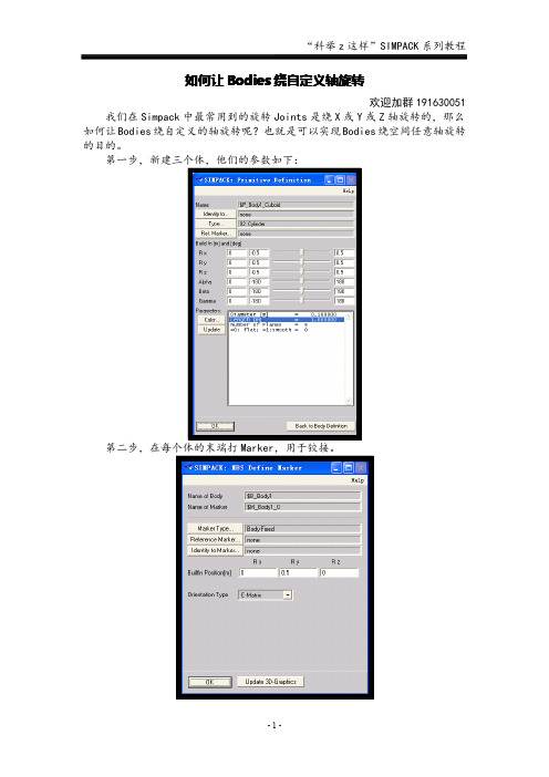
第一步,新建三个体,他们的参数如下:
第二步,在每个体的末端打Marker,用于铰接。
第三步,先建立绕X轴旋转的铰。
从参考坐标系到Body1的端部Marker,赋予初速度和初位移。
(用于对比后面的绕自定义轴旋转)
第四步,建立绕过点(x=0,z=0)和点(x=1,z=1)轴旋转的铰,我们用42号铰,从参考坐标系到Body2的端部Marker。
赋予初位移,初速度。
第五步,建立绕过点(x=0,z=0)和点(x=1,z=2)轴旋转的铰,同样用42号铰,从参考坐标系到Body3的端部Marker。
赋予初位移,初速度。
第六步,结果如图,是不是像伞?所以,有想做伞模型的盆友可以参考这个模型。
第七步,取消重力加速度,在线积分,观看运动。
基于SIMPACK软件的客车简化整车模型的搭建模板
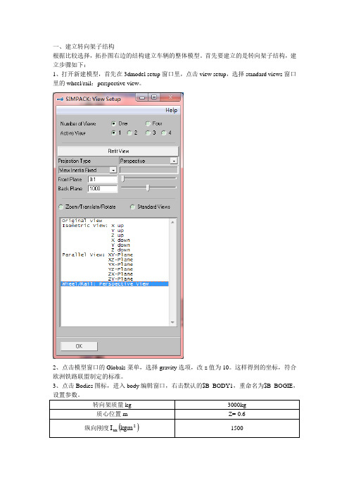
一、建立转向架子结构根据比较选择,拓扑图右边的结构建立车辆的整体模型。
首先要建立的是转向架子结构,建立步骤如下:1、打开新建模型,首先在3dmodel setup窗口里,点击view setup,选择standard views窗口里的wheel/rail:perspective view。
2、点击模型窗口的Globals菜单,选择gravity选项,改z值为10。
这样得到的坐标,符合欧洲铁路联盟制定的标准。
3、点击Bodies图标,进入body编辑窗口,右击默认的$B_BODY1,重命名为$B_BOGIE,4、在MBS Define Body窗口中,点击3D Geometry选项,设置bogie构架的几何外形。
首先选择类型(Type)为22号:wheel rail bogie,具体参数的定义如下图:H2B1然后设置参数如下图,设置初始位置(Build In)为:(0,0,-0.5)。
5、点击MBS Define Body 窗口中的Markers 按键,创建标志点,为后续创建一系悬架、二系悬架服务,创建标志点均是相对体(Body )的BFRF (Body fixed reference frame 固结在体上是坐标系)而创建的。
如图创建有六个标志点,坐标分别如下:一系悬挂(Primary suspension ):()()5.0,0.1,25.1,,x -±±=z y (m ) 二系悬挂(Secondary suspension ):()()8.0,0.1,0,,-±=z y x (m )具体步骤为,点击maker list 窗口中的new 按键,输入新建标志点的名称,如$M_BODY1_PS_1L ,创建一系悬挂力。
6、如图所示为创建好的bogie 。
8、设置轮轴的几何形状,选择类型为02号:圆柱体,具体参数设置如图:9、在轮对上创建新的标记点,坐标为()()5.0,0.1,0,,x -±=z y (m ),用于创建一系力元。
SIMPACK基础培训教程-完成模型设置

这个标签下的第三个设置是对MBS formalism 参数选择 Residual 选项, 这使计算更高效而且适用于大部分轨道 车辆仿真.
轮轨力元的预载荷作用在z向. 为了施加该预载 荷力, 在求解器初始化时, 它需要被转换为 “名义 轨道偏移“ .
名义轨道偏移改变了轨道垂向位置, 以致产生的 接触力和计算得到的预载荷有相同的值.
轨道位置变化改变了滚动半径值, 因为接触位置 通常和名义滚动半径的位置是不同的 .
由于在预载荷计算后得到新的滚动半径, 那么必 须重新应用vehicle global 中设置的速度, 以确保 车轮正确的接触滚动速度, 保持模型平衡.
1
2
L5.9
静平衡和预载荷 (2/2)
轨道车辆模型通常是按照车辆准备运行时的状态建立的. 这意味着铰接状态Joint states 已经是OK的且不需要修 改. 因此, 第二个方法预载荷计算更常用于使轨道车辆达到平衡状态.
静平衡 Static Equilibrium
车体和转向架构架的z位置被修改
预载荷 Preload
40 分钟
L5.2
模型检查 – 图形 (1/2)
检查模型的首先方法是通过车辆的3D图形 所有的物体和力元在正确的位置显示? 例如转向架位置:
L5.3
模型检查 – 图形 (2/2)
检查模型的首先方法是通过车辆的3D图形 所有力元是否连接到正确的标记点? 使用力元图形很容易对此检查.
大多数定位出错的问题是标记点或变量没有被正确地拖拽到元件中.
如果有输入值且设置是 Yes, 预载荷计算会考虑这个值并用计算后的新值覆盖它. 如果有输入值且设置是 No , 预载荷计算会考虑这个值但计算时保持不变, 不会被覆盖.
Simpack基础培训教程中文I
components (cmp)
9
Simpack 基础培训
Simpack 基础元件库(3)
控制元件Control Elements 扰动Disturbances
确定信号Deterministic 随机信号Stochastic
Theory
信号操纵Signal Manipulators
Simpack 基础培训
Simpack MBS方程: 相对坐标法 (2) 相对坐标法 (Simpack 默认)
通过矢量链描述刚体运动: (如:仅旋转铰接) 树形结构
Theory
Simpack中区分铰接Joints ( 通过铰接定义树结构) 和约 束 Constraints (闭环铰接)
IFr1(x,y,z); IFA1(a,b,g) IFr2(x,y,z); IFA2(a,b,g)
Theory
1
3
IFr3(x,y,z); IFA3(a,b,g)
惯性坐标系 inertial frame
位置
速度
加速度
位置
方向
12
r ( x, y, z )
A (a , b , g )
r A
r A
2
Simpack 基础培训
Simpack 培训一览表
Theory
基础培训
刚柔耦合
汽车模块
联合仿真
铁路模块
NVH频域
风机模块
C ----------------------------------------------------C task = 0 : I/O-Values C ----------------------------------------------------C Parameters C ---------C Name '123456789012345678901234567890' par_str( 1) = 'Stiffness ' par_str( 2) = 'Damping ' par_str( 3) = 'Reference Marker '
基于SIMPACK软件的客车简化整车模型的搭建-说明
一、 建立转向架子结构1、 新建模型2、 设置gravity 。
3、 设置转向架质量、质心位置和刚度。
4、 设置转向架的几何外形,type 为“wheel rail bogie ”。
5、 创建BOGIE 上的6个makers 。
一系悬挂(Primary suspension ):()()5.0,0.1,25.1,,x -±±=z y (m ) 二系悬挂(Secondary suspension ):()()8.0,0.1,0,,-±=z y x (m )6、 设置轮对的质量、质心位置和刚度。
7、 设置轮对的几何形状。
type 为“cylinder ”。
——长度是不是也给错了,应该是2而不是2.2?8、 创建轮对上的2个makers 。
坐标为()()5.0,0.1,0,,x -±=z y (m ),用于创建一系力元。
——是不是数据给错了,-0.5应该是0?。
9、 为了定义轮对的铰接,创建参考坐标系上的2个makers 。
坐标分别为()()5.0,0,25.1,,x -±=z y m 。
——1在体定义窗口中右击$B_WS1,选择复制,右击空白处选择粘贴,重命名为$B_WS2,再用同样的方法新建$B_WS3、$B_WS4。
粘贴创建的体$B_WS2与目前$B_WS1的位置重合,通过铰接定位以后,$B_WS2的maker 点位置也相应改变。
10、 搭建虚车体。
虚车体在SIMPACK 建模中的作用很大,尤其在此处,通过建立虚车体,可以在子结构中设置车体与转向架的作用力元,在整体建模中,只需将虚车体与实际的车体固结在一起,即可实现力的作用。
因此,对虚车体的要求是质量、转动惯量均足够小,不影响实际车体的动力学性能。
新建虚车体,命名为$B_DUMMY ,进入全局参数的窗口,新建参数并命名为$P_DUMMY ,赋值为1E-7,点击Assign 确定。
在体定义窗口,右击质量数值输入窗口,出现value given by substitution variables 提示,点击进入,选择$P_DUMMY ,并同样给转动惯量赋值为$P_DUMMY 。
SIMPACK软件基础及应用讲稿(第三章_Create_Pendulum_Model)
SIMPACK软件基础及应用
Step 8 Off Line Integration
SIMPACK软件基础及应用
Step 8-1 Off Line Integration
SIMPACK软件基础及应用
Step 8-2 Off Line Integration
SIMPACK软件基础及应用
Extend Pendulum Model
Step 3 Adding a Marker to the Body1
The marker is used as: •Linking points for joints •Linking points for force elements •Reference points for sensors
ParVariation(参变量) 这个SIMPACK特征是非常有用的。如果需要求一个不同参数 变化,SIMPACK能够自动完成。用户可以不必直接改变参数, 就可以利用SIMPACK去看变化参数的影响(比如体的质量)。 在系统运动情况下,许多不同的SIMPACK解算模块都可以利 用这个参数变化。 Optimization(优化) 基本思想和参数变化比较相近,得到优化的参数根据选择的标 准最小化原则可以得到修改(比如,加速度的均方根值,RMS 值)。SIMPACK使用了一个复杂的代数方法去评估结果的性 能,这就可以在一个较短的迭代时间内给出最优的参数。 (Pareto_Optimal)。优化过程既不受限制于一种计算方法, 也不受制于仿真模型。优化的参数可以从几个优化的标准考虑 后得出,比如一个轨道车辆参数问题, 如乘坐舒适度、轨道质量和安全性就应该得到全部考虑。
SIMPACK软件基础及应用
Data information of Double Pendulum
SIMPACK软件基础及应用(第三章_Create Pendulum Model)
SIMPACK软件基础及应用 软件基础及应用
Step 8-2 Off Line Integration
SIMPACK软件基础及应用 软件基础及应用
Extend Pendulum Model
SIMPACK软件基础及应用 软件基础及应用
Data information of Double Pendulum
Step 2 Modify the Body
SIMPACK软件基础及应用 软件基础及应用
Step 3 Modify the Jiont
SIMPACK软件基础及应用 软件基础及应用
Step3_1 Initial Position
SIMPACK软件基础及应用 软件基础及应用
Step 4 Define g-Vector
SIMPACK软件基础及应用 软件基础及应用
Data information of Pendulum
SIMPACK软件基础及应用 软件基础及应用
Data information of Pendulum
SIMPACK软件基础及应用 软件基础及应用
Step 1:Open a Model
SIMPACK软件基础及应用 软件基础及应用
SIMPACK软件基础及应用 软件基础及应用
Step 6_2 3D geometry ---axle
SIMPACK软件基础及应用 软件基础及应用
Step 6_3 3D geometry ---change name to hand
SIMPACK软件基础及应用 软件基础及应用
Step 6_4 3D geometry ---hand
Step 12-2 Operate
SIMPACK软件基础及应用 软件基础及应用
- 1、下载文档前请自行甄别文档内容的完整性,平台不提供额外的编辑、内容补充、找答案等附加服务。
- 2、"仅部分预览"的文档,不可在线预览部分如存在完整性等问题,可反馈申请退款(可完整预览的文档不适用该条件!)。
- 3、如文档侵犯您的权益,请联系客服反馈,我们会尽快为您处理(人工客服工作时间:9:00-18:30)。
How to model a two axle bogie1. GeneralThe basic component of all wheel/rail models is a bogie. This guide shows, how to set-up a basic bogie structure. It gives an overview about the topology of bogie models and should be a fundamental model for your further work. The model can be further extended for use in various different applications.2. Additional FeaturesDuring the model set-up it will also be shown, how to define substitution variables and apply them to the model. It’s a very efficient method, which allows modifications to be easily made to complicated structures.3. Creating an Example Model3.1. ConceptThe model is a simple model to allow you to understand the topology and the concepts in SIMPACK. First a short substitution variable set is to be defined, to aid an efficient model set-up and further modifications to the model. Two identical wheelsets will then be defined in different positions and a bogie frame using the pre-defined substitution variables. Finally a simplified primary suspension will be set-up; using component force elements between the wheels and the bogie frame. To prepare the solver, there will be a number of globals such as wheel/rail profiles and velocity, which are to be defined.3.2 Modelling3.2.1Create a new model. Then switch, as usual, the gravity to the positive z direction (Menu Globals/gravity) and adjust the view to …Wheel/Rail Perspective View“.3.2.2Define the following substitution variables to help an efficient model set-up.Under the icon above, define new substitution variables as shown in the screenshot below.$_WS_BASE = 2.5000000000E+00 $_SUSP_BASE_LAT = 2.0000000000E+00 $_PRIM_SUSP_X = $_WS_BASE/2 $_PRIM_SUSP_Y = $_SUSP_BASE_LAT/2 $_PRIM_SUSP_Z = -5.0000000000E-01 $_NEG_PRIM_SUSP_X = -1*$_PRIM_SUSP_X $_NEG_PRIM_SUSP_Y = -1*$_PRIM_SUSP_Y3.2.3Rename $B_Body1 to $B_WS1 and enter the data for the body definition as shown in the figure below.3.2.4Modify the …3D Geometry“ and replace the Cuboid by a Cylinder with the following data;Diameter: 0,18mLength: 2,00m3.2.5Modify the wheelset joint as shown in the figure below ( Joint Type 07, No. of DOF = 6 ) and enter the menu …Generate/Update Wheel-Rail Elements of Joint“.3.2.6In the window below, please note that the bodies for the rails can be changed as well as the bodies for the left and right wheel. Click on OK!3.2.7Define the track under the menu globals/track and accept the default settings with OK!3.2.8Define a new body “$B_WS2” and repeat the instructions from 3 to 7. In the Joint definition window type 2.5 m for the arc length!3.2.9Create new markers in the Body definition window for the wheelsets left and right side using the defined substitution variables!3.2.10Define a new body, called $B_BF with the following parameters.3.2.11Define the joint of the bogie frame (Joint type 7, 6DOF) and set the arc length to 1.25 m.3.2.12Define new markers on the bogie frame using the substitution variables!3.2.13Define also 4 new Force elements for the primary suspension with the following parameters.Force type: 05 Spring-damper parallel cmpFrom Marker of the primary suspension is always located at the Bogie_frame and not at the rotating wheelset. (SIMPACK uses the from marker as reference for the calculations)To Marker is on the wheelset.Force Parameters:Cx: 100000000N/mCy: 100000000N/mCz: 5000000N/mDx,Dy,Dz: 20000Ns/m3.2.14Finally define some global settings! In the menu Globals/Vehicle Globals define the velocity for the model and click on …apply as defaults“ Leave all other settings as default and close the window. In the menu views/view setup switch on moved view. Select in the menu calculation assemble system and save the model!3.2.15Close the Model Setup window and define the solver settings in the Main window! In the Menu Calculation/Time Integration/Configure set end time of the simulation to 5 seconds save the settings and exit the window. Click on the icon below to perform the time integration + measurements!3.2.16In the post-processing general plots look at, for example, the force element output values.3.2.17Nominal Force CalculationWith the icon above or in the calculation menu in the main window you can open the nominal force calculation block, looks like below.Pick in the window on selection of force parameters and pick in the new window; “Init with all possible forces”. Than close the window and pick perform. After the calculation save the results and reload your model.3.2.18By nominal force calculation you reached with your system an equilibrium state, so it´s possible to carry out eigenvalue calculations.Also in the menu calculation you could find eigenvalues or start the block directly using the icon above. Just pick on perform, save the results and reload the model. In the model setup window; menu Animation/Model Shapes you can open a window like below. Choose on of the eigenvalues, set the scaling and start the animation.4. ApplicationThis model is a simple representation of a bogie used to analyse dynamic behaviour. Bogie models of this kind have been used in the eighties and early nineties for investigating stability and curving behaviour of railway vehicles. This type of model requires the real primary suspension design to be reduced to a compact force element with resulting stiffness and damping coefficients in the x, y, and z directions. Kinematically non-linear effects caused by axle boxes with trailing arms, for example, are not considered with this model. Additionally, each design modification, e.g. a different bushing of a trailing arm, requires a recalculation of the contact spring parameters.Today, with the state of the art SIMPACK Wheel/Rail, more advanced and versatile models can be achieved. Bogies with a higher level of detail are covered in the SIMPACK Wheel/Rail training.。