TDS measurement for Hi-speed Processor
蔡勤科技 TDS 820 数字高速波形仪概述说明书
TDS 820FeaturesSpecs Ordering Information Digital Sampling Oscilloscopes TDS 820This product is discontinued.CharacteristicsSIGNALAcquisitionSystemTDS 820TDS 820 Opt. 1DChannels22Rise time58.3 ps43.8 ps Bandwidth(0.35/rise time)6 GHz8 GHzMax operatinginput voltage2 V p-p; ±3 V DC 1 V p-p; ±1.5 V DCSensitivity 2 m V/div to200 mV/div1 mV/div to100 mV/div Random noise 1.2 mV max, 600µV typical600 µV max, 300µV typicalDC Gain Accuracy - ±0.7% after user-initiated automatic vertical calibration.Vertical Resolution - 14-Bits (Approx. 16,384 levels over 10.24 vertical divisions).Input Impedance - 50 Ohm.Acquisition ModesNormal - One sample acquired with each trigger event. Envelope - Max/min values acquired over one or more acquisitions.Average - Waveform averages selectable from 2 to 10,000. Time Base SystemTime Bases - Main, Delayed.Time/Division Range - 20 ps/division to 5 ms/division in 1-2-5 steps or settable from the numeric keypad in 5 ps steps.Delta time measurement accuracy -Channel Deskew - Up to 100 ns (each channel).Record Length - 500, 1000, 2000, and 5000, and 15,000 samples per channel.Pre -Trigger View Time - 1.5 ns.Triggering SystemTrigger Sources - External input, internal rate generator, CH 1, CH 2.External Trigger Sensitivity - 40 mV p-p from DC to 200 MHz, increasing linearly to 200 mV p-p at 2 GHz.External Trigger Minimum Pulse Width - 0.25 ns.Internal Trigger Sensitivity - 80 mV p-p from DC to 200 MHz, increasing linearly to 400 mV p-p at 1 GHz.Trigger Delay Jitter - 3 ps RMS + 30 ppm of time base delay.Holdoff Range - 15 µs to 2 s.DisplayWaveform Style - Dots or vectors. Infinite and variable persistence from 250 ms to 10 s.Gray Scaling - With variable persistence selected, waveform points gradually decay through 16 levels of intensity, providing "z-axis" information about rapidly changing waveforms.Graticules - Full, grid, cross hair, frame.Format - YT and XY.CRT Type - 7 in. diagonal, magnetic deflection. Horizontal raster-scan. P4 White phosphor.CRT Resolution - 640 horizontal by 480 vertical displayed pixels.Measurement SystemAutomatic waveform measurements -Period FrequencyHigh Low+ Width- Width Maximum MinimumRise FallPeak to Peak Amplitude+ Duty Cycle- Duty Cycle+ Overshoot- Overshoot Propagation Delay Burst WidthMean Cycle MeanRMS Cycle RMSPhase Cycle Area+ Cross- CrossAreaContinuous update of up to four measurements on any combination of waveforms. Snapshot mode shows all measurements on the selected waveforms.Thresholds - Settable in percentage or voltage.Cursor Measurements - Absolute, Delta; Volts, Time, Frequency.Cursor Types - Horizontal bars (volts); Vertical bars (time); Paired (volts and time).Waveform ProcessingWaveform Functions - Interpolate-selectable sin(x)/x or linear, Average, FFT, integrate, and differentiate.Arithmetic Operators - Add, Subtract, Multiply, Invert. Autosetup - Single button, automatic setup on selected input signal for vertical, horizontal and trigger systems.Computer InterfaceGPIB (IEEE -488.2) Programmability - Full talk/listen modes. Control of all modes, settings, and measurements. Hard CopyFormats - HP ThinkJet, Epson, Postscript, Interleaf, DeskJet, LaserJet, EPS Monochrome, EPS Color, TIFF, PCX, BMP, HPGL.Optional Hardcopy Interface - Centronics and RS-232C. StorageWaveforms - Up to 15 K points.Setups - 10 front-panel setups.Power RequirementsLine Voltage Range - 90 to 250 V RMS.Line Frequency - 47 to 63 Hz.Power Consumption - 250 W max.Environment and SafetyTemperature - Operating: 0 to +50°C. non-operating: -40 to +75°C.Humidity - Operating and non-operating: Up to 95% relative humidity at or below +40°C; to 75% relative humidity from +41°C to 50°C.Altitude - Operating: 15,000 ft. non-operating: 40,000 ft. Electromagnetic Compatibility - Meets MIL-STD-461C, CE-03, Part 4, Curve # 1, RE-02, Part 7; meets VDE 0871, Category B, FCC rules and regulations, Part 15, Subpart B, Class A.Safety - UL3111-1, CSA1010.1, EN61010-1, IEC61010-1. Physical CharacteristicsDimensions mm in. Height1937.6 with acc. pouch2369.3 Width44517.5Depth with front cover43217Weightkglbs.Net 13.229.1Shipping 23.652Top of PageFeaturesSpecsOrdering Information The TDS Series complies with IEEE Standard 488.2-1987, and with Tektronix Standard Codes and Formats. Tektronix Measurement products are manufactured in ISO registered facilities.49A-10733-3p88, 06/1997, 09/01/1999© Copyright Tektronix, Inc | *****************| Privacy Policy。
泰克_TDS3054B示波器使用..

1-3.面版說明 ( FRONT PANEL ) 輸入通道 ( CHANNELS ) 通道 1 / 2 / 3 / 4 的控制區, 此控制區內主要是提供信號 軌跡的開啟 關閉、垂直電壓 檔位的控制、輸入 阻抗的 匹配設定 … 等。 操作面版內容 1.SELECT CHANNEL 1 / 2 / 3 / 4 2. TRACE ON / OFF 3. Vertical / horizontal Position 4. Vertical / horizontal Scale 5.Math and Ref 6. ZOOM 7.MEMU 8.Delay+Set to50% 9.FORCE TRYIG 10.TRYIC MODE 11.WAVEFORM I信號 ( ZOOM ) 7.MEMU 可設定觸發類型、通道、觸發耦合、觸發方式、觸發電平、觸發模式,耦合電阻、相位 、帶寬、粗細標度、探頭設置等 8.Delay+Set to50% Delay:快速設置display level(顯示觸發參考位元準)到示波器螢幕上。 Set to 50%:快速設置TRIGGER LEVEL(觸發參考位準) 到示波器螢幕上。 9.FORCE TRYIG 強力觸發:用來擷取高速不常出現的突發信號或雜波.
1-1.外觀 ( FEATURE ) 1.DISPLAY 螢幕顯示及觀察波形之區域
2.POWER ON/OFF 電源開關
3.FRONT PANEL 示波器的操作及控制區域 4.CHANNEL INPUT 連接測試棒信號輸入端 5.CAL BNC SETUP 被動式測試棒須作校正, 使輸波形得到正確的補償 6.FLOPPY DRIVE 儲存數據資料及圖形的周邊設備
2.簡易操作 ( BASIC )
3.阻抗匹配(COUPLING ) 4. 觸發 5.量測
Yokogawa Q7607 光脉冲测试设备说明书
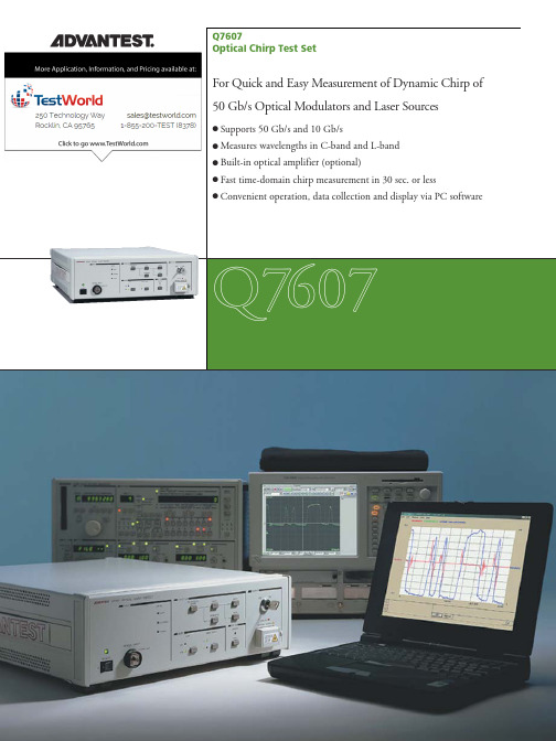
When measurement made ten timesOptical input Optical output Optical Amplifier is unnecessary if the built-in option (OPT7607+10) is used.OptionsBuilt-in Optical Amplifier: OPT7607+10 Retrofit Optical Amplifier:OPT7607+10AAccessory (supplied with the system)Chirp MeasurementSoftware:PQ76000402-CDSeparately Sold AccessoriesFC connector adapter:A08161 SC connector adapter:A08162 ST connector adapter:A08163 Rack mount kit:EIA, with Front handles A02708JIS, with Front handles A02709EIA, without Front handles A02718JIS, without Front handles A02719 *1)At 23 ±5°C*2)P: optical average power*3)100 MHz as standard, 1 dB down*4)Total output of optical power5 Q7607-2E Jan. ‘03Please be sure to read the product manual thoroughly before using the products. Specifications may change without notification.SpecificationsFunctionsMeasurement principle:Using the conversion characteristicsbetween optical frequency and intensityin the built-in optical-fiber-type Mach-Zehnder interferometer, the instrumentconverts the dynamic chirp (opticalfrequency modulation) into a change inoptical power FM. By controlling thediscrimination point of the interferometer,FM is either added to or subtracted fromthe intensity IM of the optical input signal. Polarization compensation: Automatic polarization compensation bythe internal optical-fiber-type polarizationcontrollerBuilt-in optical amplifierwith automatic gainadjustment option(OPT7607+10): Available as an option, the Q7607 has abuilt-in optical amplifier with automaticgain adjustment.The optical output power is approx.0 dBm, regardless of the optical inputpower.Performance Specifications*1)Wavelengthmeasurement range:Q7607; 1510 to 1610 nmQ7607+10; 1530 to 1610 nmOptical input power range:-10 to 10 dBmFrequency conversionaccuracy:within ±15%FM demodulationcoefficient (50 G/10 G)*2):P x 0.021/GHz / P x 0.042/GHzFree Spectral Range(50 G/10 G):300 GHz ±15 GHz / 150 GHz ±15 GHz Demodulation bandwidth (50 G/10 G)*3):100 Hz to 100 GHz / 100 Hz to 50 GHz Deviation of demodulationfrequency (50 G/10 G):135 GHzpp or less / 65 GHzpp or less Insertion loss:Q7607; 13 dB or lessOptical output power:Q7607+10; -3 to 0 dBm*4)Input light polarizationcompensation:Automatically controlledInput/Output SpecificationsOptical input/output: FC/PC connector(changeable to SC or ST type)GPIB: In accordance with IEEE488-1978Optical remote interlock:BNC connector (for OPT7607+10/10A)General SpecificationsOperating environment:Ambient temperature; 0 to +40°CRelative humidity; 85% max.(no condensation)Storage environment:Ambient temperature; -20 to +60°CRelative humidity; 90% max.(no condensation)Power supply:AC100–120 V, AC220–240 V, 50/60 Hz,100 VA or lessAutomatic switching between the 100and 200 V systemsDimensions:Approx. 132 (H) x 424 (W) x 500 (D) mm(Approx. 5.2 (H) x 16.7 (W) x 19.7 (D) in.) Mass:13 kg (28.7 lbs) or lessBulletin No.Q7607-332E Jan. ‘03D©2002 ADVANTEST CORPORATIONPrinted in JapanADVANTEST CORPORATIONShinjuku-NS building, 4-1Nishi-Shinjuku 2-chomeShinjuku-ku, Tokyo 163-0880,JapanTel:+81-3-3342-7500Fax:+81-3-5322-7270http://www.advantest.co.jpNorth America, Canada, Mexico:Advantest America Measuring Solutions, Inc.Head Office258 Fernwood Avenue Edison, NJ 08837, U.S.A.Tel:+1-732-346-2600Fax:+1-732-346-2610/ProdServices/instr.htmSanta Clara Office3201 Scott Blvd., Santa Clara, CA 95054, U.S.A.Tel:+1-408-988-7700 Fax:+1-408-987-0688Europe:Rohde & SchwarzEngineering and Sales GmbHMühldorfstraße 15D-81671 München, Germany (P.O.B. 80 14 29D-81614 München, Germany) Tel:+49-89-4129-13711Fax:+49-89-4129-13723Korea:Advantest Korea Co., Ltd.16F, MIRAEWASARAM Bldg., 942-1, Daechi-Dong,Kangnam-ku, #135-280, Seoul,KoreaTel:+82-2-3452-7157Fax:+82-2-3452-0370China:Advantest (Suzhou) Co., Ltd.Shanghai Branch Office5F, No.46 Section FactoryBuilding, No.555 Gui Ping Road,Caohejing, Hi-Tech Area,Shanghai, China 200233Tel:+86-21-6485-2725Fax:+86-21-6485-2726Beijing Branch OfficeRoom 517, Beijing Fortune Bldg.,5 Dong San Huan Bei-Lu, Chan Yang District, Beijing, China 100004Tel:+86-10-6590-8170Fax:+86-10-6590-8175Taiwan:Advantest Taiwan Inc.No.1 Alley 17, Lane 62,Chung-Ho Street, Chu-Pei City, Hsin Chu Hsien, Taiwan R.O.C Tel:+886-3-5532111Fax:+886-3-5541168Singapore, Malaysia, Thailand, Indonesia,Philippines, Vietnam:Advantest (Singapore) Pte. Ltd.438A Alexandra Road, #08-03/06Alexandra Technopark Singapore 119967Tel:+65-6274-3100Fax:+65-6274-4055。
NOV TDS-11HD高效力耐久顶驱说明书

As the land drilling market demands high torque at high speed, contractors require top drives that meet demands for longer laterals and deeper wells. The TDS-11HD builds upon the field-proven performance and brand quality of the TDS 11SA top drive, offering extra power and torque for increased drilling requirements.Featuring two 600-horsepower induction motors plus gear box internals, the TDS-11HD yields more torque than previous top drive models in its size and class. The 500-ton main thrust bearing ensures hoisting capacity to handle heavy pipe. This means faster and deeper drilling, both vertically and horizontally, to help you reach your pay-zone in even the most demanding formations.Offering the advantage of continued support through the global NOV network, engineering and aftermarket, the TDS-11HD enables drilling of wells beyond the technical limits of the standard top drive.Contact your local NOV representative to learn how the TDS-11HD can improve your performance.Related Products: TDS-11SAETDS-11HDIncrease power and torque by up to 45%Higher torque and more power enables faster and deeper drilling, even in the most demanding well operationsTDS-11HDTwo 600-horsepower induction motors• Dramatic increase in horsepower yields significantly more torque• Enables drilling of wells beyond the technical limits of the standard top drive 500-ton main thrust bearing• Ensures hoisting capacity to handle heavy pipe • API 8C hoisting and rotating; dynamic and staticTorque Curves for TDS-11SA and TDS-11HDTorque compareFeatures and benefitsUp to 45% more power and torque80,00070,00060,00050,00040,00030,00020,00010,000D r i l l p i p e t o r q u e (ft -l b )0 50 100 150 200 250TDS Speed (RPM)TDS-11HD 1200HPTDS-11SA 800HPNote: 560V, +40 C° Rating*-40°C is the standard operating temperatureFits any mast currently using TDS-11SA Top drives • Minimizes downtime by using configurable components• Delivers significantly more power in virtually the same footprint Available software enhancements • SoftSpeed II™, Twister。
数位示波器的基本原理﹑操作及USB 2.0物理层测试简介
20
存储长度 (Memory Depth)
操作时以记录长度(Record Length)来表示
以点(Point)为单位来记录波形 示波器儲存采样点数据 记录长度可从1000点到数200M点 在相同采样率的条件下,记录长度愈长,记录 的时间愈长
– USB 2.0装置的设计人员必须恰当地鉴定其设计并检验产品是否符合业界标准。因此,恰当的测试
工具对USB-IF兼容性测试极其重要,
38
USB2.0 一致性测试
4 Three categories of Compliance testing 0 Physical layer (Electrical Test) 0 Protocol layer 0 Interoperability testing
– 使用1GHz带宽,即350ps上升时间(0.35/1G)的示波器(示波器带宽大 于输入信号带宽3倍)测量值如下 :
测量值 上升时间 = (1ns )2 + (350 ps )2 = 1.06 ns
12
多快才是足够快?
示波器上升时间
等于信号的上升时间 等于信号的上升时间1/2 等于信号的上升时间1/3 等于信号的上升时间1/5
USB2.0 物理层一致性测试
Compliance Physical Layer Testing
37
Brief Introduction to USB 2.0
USB 2.0是一种串行总线,使用4条线-VBUS、D-、D+和接地。D-和D+传送数据。VBUS 为设 备供电,从主机或集线器获得主电源
Amplifier ADC Trigger
Tektronix 数字波形捕获器(TDS6154C、TDS6124C、TDS6804B和TDS66

Features & BenefitsBandwidths of 15GHz (TDS6154C),12GHz (TDS6124C), 8GHz(TDS6804B) and 6GHz (TDS6604B) Rise Times to 19ps 20 to 80%(28ps 10 to 90%) on TDS6154C Typical Rise Time, with Channel-matched, User-selectable DSP 40GS/s Real-time Sample Rate on Two Channels *1, 20GS/s Real-time Sample Rate on All Four Channels with 500fs/sample Interpolated PointsUp to 64Msamples on Two Channels *1, up to 32Msamples Record Length on All FourChannels with MultiView Zoom ™Function for Quick Navigation MyScope ®Custom ControlWindows Enhance Productivity Right Mouse Click Menus for Exceptional EfficiencyPinpoint ™Triggering Provides the Most Flexible and Highest Performance Triggering, with Over 1400 Combinations to Address Virtually Any Triggering Situation Serial Pattern Triggering up to 3.125Gb/s with 8b/10b Protocol Triggering Serial Data Analysis and Compliance at Rates of 6.25Gb/s and Above OpenChoice ®Software with Microsoft Windows XP OS Delivers Built-in Networking and AnalysisTechnology Specific Software Solutions Provide Built-in Domain Expertise for Serial Data, Jitter, Ethernet, DVI, USB 2.0, Communications and Power Measurements System Includes: Dual Processor System (2.8GHz Pentium 4 and 583MHz PowerPC), High Resolution XGA Display, Front Panel CD-R/W, Front Panel USB 2.0 Port and 1000Base-T Network ConnectionApplicationsSignal Integrity, Jitter and Timing AnalysisValidation, Debug, Characterization and Compliance of Next Generation Digital Designs Computer, Datacom, StorageArea Network Equipment Designs and High-speed Backplanes High Energy Physics Measurements and Data Acquisition*1For C Model versions only.Digital Storage OscilloscopeTDS6000B/C SeriesUncompromised Performance Oscilloscope Solution — Probing, Acquisition, Analysis, Compliance, and DebugTDS6000B/C Series digital storage oscilloscopes provide unprecedented performance along with a complete feature set designed to address design validation, debug and compliance chal-lenges of next generation computer,datacom and communications equipment.High bandwidth, high sample rate and deep memory also provide the ideal solution for data acquisition applications. Uncompromised Acquisition You won’t need to need to trade-off bandwidth, record length and sample rate for your serial data measurement and analysis needs. The TDS6000C DSOs provide acquisition architecture with 40GS/s maximum sample rate and 64Msamples record length on two channels (20GS/s and 32Msamples on each of the four channels simultaneously),for the acquisition power you need. Theyprovide the ultimate combination of band-width, sample rate and record length for the fastest signals. The TDS6154C provides matched 15GHz performance across any two channels using advanced,T ektronix-proprietary DSP enhancement,important for high-speed, channel-to-channel measurements. The user-selectable DSP filter on each channel provides magnitude and phase correction, plus extension of the analog bandwidth to 15GHz for more accurate signal fidelity on high speed measurements – easily capturing the fifth harmonic of 3.0GHz embedded clocks used in next generation 6.0Gb/s serial data standards, and even the third harmonic of 5GHz clocks being developed for future systems. The DSP filter on each channel can also be switched off to take advantage of true 12GHz analog bandwidth for applications needing the highest available raw data capture.Digital Storage Oscilloscope TDS6000B/C Series2Digital Storage OscilloscopeTDS6000B/C SeriesDigital Storage Oscilloscopes • /oscilloscopes 3Digital Storage Oscilloscope TDS6000B/C Series4TDS6604BTDS6804BTDS6124CTDS6154CHardware Bandwidth Limits Full,250MHz or 20MHz(Requires TCA-1 MEG Adapter)Input Sensitivity,50ΩFull-scale 50mV to 10V (5mV/div *1to 1V/div).Full-scale is the peak-to-peak digitizerrange at a given sensitivity.Volts/div = Full-scale ÷10≥Digital Storage Oscilloscopes • /oscilloscopes 5Digital Storage OscilloscopeTDS6000B/C SeriesCharacteristicsDigital Storage Oscilloscope TDS6000B/C SeriesDigital Storage Oscilloscopes • /oscilloscopes 7Digital Storage OscilloscopeTDS6000B/C SeriesDigital Storage Oscilloscope TDS6000B/C SeriesDigital Storage Oscilloscopes • /oscilloscopes 9Digital Storage OscilloscopeTDS6000B/C SeriesDigital Storage Oscilloscope TDS6000B/C SeriesDigital Storage Oscilloscopes • /oscilloscopes 11Digital Storage OscilloscopeTDS6000B/C SeriesCopyright © 2006,Tektronix,Inc.All rights reserved.Tektronix products are covered by U.S.and foreign patents,issued and rmation in this publi-cation supersedes that in all previously published material.Specification and price change privileges reserved.TEKTRONIX and TEK are registered trademarks of Tektronix,Inc.All other trade names referenced are the service marks,trade-marks or registered trademarks of their respective companies.07/06 JS/WWW55W-14873-9。
CON 200 Conductivity TDS °C Meter说明书
CON 200 Conductivity/TDS/°C Meter •One button press switches from conductivity to TDS readings •Selectable Manual or Automatic Temperature Compensation (ATC)•Selectable temperature coefficient and cell constant •Stores and recalls up to 16 readings•Manual or Auto-ranging for conductivity measurements in five ranges; auto-ranging in TDSThis microprocessor-based meter easily switches from conductivity to TDS readings (in ppm, KCl, NaCl or 442). Calibrate to any combination of five conductivity or TDS calibration points. Hold function; Auto-Off; Ready function. Conductivity/temperature cell included.TypeConductivity TDSTemp 0.00-19.99 µS, 0.0-199.9 µS, 0.00-9.99 ppm, 10.0-9.99 ppm,0 toRange 0-1999 µS, 0.00-19.99 mS,100-999 ppm, 1.00-9.99 ppt,100°C 0.0-199.9 mS 10.0-99.9 ppt, 100-200 ppt Resolution0.01 µS, 0.1 µS, 1 µS,0.01 ppm, 0.1 ppm, 1 ppm,0.1°C 0.01 mS, 0.1 mS 0.01 ppt, 0.1 ppt, 1 pptAccuracy ±1% full scale ±0.5°CWD-35607-20 CON 200 meter with epoxy/platinum cell.9.2"L x 9.2" W x 2.75"H (boxed). Shpg wt 2 lbs .............................................WD-35607-50 Replacement cell;epoxy/platinum with built-in temperature sensor. Cell constant = 1.0. 5"L x 0.5" dia with 2.5 ft cable. Shpg wt 0.43 lb ....Ask for bulletin Con B3 for complete specifications. Patent Des. # 354,921.CON 300 Conductivity/TDS/°C Meter with RS-232 Output•Download data to PC or printer with free PC software•Selectable Manual or Automatic Temperature Compensation •Selectable temperature coefficient and cell constant •Manual or Auto-rangingfor conductivity measurements;auto-ranging in TDSThis advanced meter features RS-232 output—download readings to your PC or printer. Free software creates filesready to import into spreadsheet applications. Switch from conductivity to TDS readings with one button press. Calibrate up to 5 Conductivity or TDS calibration points. Stores and recalls up to 16 sets of measurements. Hold function; Auto-Off; Ready indicator. Conductivity/temperature cell included.Type Conductivity TDSTemp 0.00-19.99 µS, 0.0-199.9 µS, 0.00-9.99 ppm, 10.0-99.9 ppm,0 to Range 0-1999 µS, 0.00-19.99 mS,100-999 ppm, 1.00-9.99 ppt,100°C 0.0-199.9 mS 10.0-99.9 ppt, 100-200 ppt Resolution 0.01 µS, 0.1 µS, 1 µS,0.01 ppm, 0.1 ppm, 1 ppm,0.1°C 0.01 mS, 0.1 mS 0.01 ppt, 0.1 ppt, 1 pptAccuracy±1% full scale±0.5°CWD-35607-30 CON 300 meter with epoxy/platinum cell.9.2"L x 9.2" W x 2.75"H (boxed). Shpg wt 2 lbs ..........................................WD-35607-50 Replacement cell;epoxy/platinum with built-in temperature sensor. Cell constant = 1.0. 5"L x 0.5" dia with 2.5 ft cable. Shpg wt 0.43 lb .......Ask for bulletin Con B3 for complete specifications. Patent Des. # 354,921.See page 27 for a portable printer to use with the CON300!。
YSI EC3175 电导性 TDS 温度仪操作手册说明书
Operation ManualMODEL EC3175Microcomputer Based Conductivity/TDS/Temperature Benchtop MeterCONTENTS GENERAL INTRODUCTION (2)INITIAL INSPECTION (2)POWER INPUT (2)INSTALLING THE BATTERIES (3)DISPLAY&KEYS FUNCTIONS (4)A.Display (4)B.Keys (5)OPERATIONAL PROCEDURES (6)A.Preparing Standard Solutions (6)B.Calibration (6)C.Conductivity Measurements (8)ERROR DISPLAYS AND TROUBLESHOOTING (9)SPECIFICATIONS (10)WARRANTY (11)Thank you for selecting the EC3175meter.The EC3175is a precision tool that measures Conductivity,TDS and Temperature.A built-in microprocessor stores,calculates and compensates for all parameters related to Conductivity,TDS and Temperature determinations.This meter has a waterproof IP54case.The mechanical keys are highly reliable with tactile and audio feedback.This meter is powered by six AAA-size alkaline batteries or with a UL approved AC adapter(OUTPUT:DC9V).The meter also displays a“BAT”message when the batteries are in need of replacement. Re-calibration is not required when power is restored.The front of the meter has a large LCD that displays Conductivity or TDS and Temperature simultaneously along with user prompts and mode indicators.The unit prompts the user through calibration and measurement procedures.The model EC3175micro-processor allows the user to easily recalibrate the parameters for the probe.A few keystrokes will adjust all the parameters for conductivity and will also give the user the option to select four types(0.01,0.1,1.0,10.0)of probe cell constant for a better selection of available probes and applications. And the user can input K value of the cell by keypad directly.The system simultaneously displays temperature in℃along with either Conductivity or TDS.The user can switch back and forth from all these displays by just pushing a single“MODE”key.Other features include automatic conductivity ranging,automatic temperature compensation,long battery life,and50/60Hz AC noise rejection.This meter is user-friendly for laboratory application.Carefully unpack the unit and accessories.Inspect for damages made in shipment.If any damage is found,notify your Jenco representative immediately.All packing materials should be saved until satisfactory operation is confirmed.The model EC3175can be powered by an115V or230VAC adaptor as well as6“AAA”alkaline batteries.Check the label on the AC adaptor supplied with the instrument to make sure that the AC linevoltage is correct.If the wrong AC adaptor is supplied,notify your Jenco representative immediately.To insert the batteries into the meter,follow the procedure outlined below.e two hands to flip the two buckles and battery cover toexpose the battery compartment.(Figure1.)2.Note the polarity and insert the six AAA batteries into thebattery compartment correctly.3.Replace the battery cover.Figure1:Battery compartmentA.Display1 234 5 67891011 Figure2:Active LCD screen1.mS-Millisiemens,indicates Conductivity measurement.7.mg/L-Milligrams/Liter indicates TDS measurement.2.BAT-Low battery indicator.8.CELL K=Indicates conductivity cell constant value.-Microsiemens,indicates Conductivity measurement.9.%/℃-Indicates Temperature Coefficient4.CAL-This will be displayed when the unit enters into the calibration mode.10.MAIN DISPLAY-For Conductivity and TDS values.5.AUTO-Auto ranging indicator 11.SECONDARY DISPLAY-For temperature in℃display.6.ATC/MAN-ATC,indicates Compensated Conductivity.MAN,indicates Uncompensated Conductivity.B.KeysA.Preparing Standard SolutionsSuitable conductivity standards are available commercially or the user can prepare them using research grade reagents.Here are some standard solutions the user can prepare to calibrate the probe of the model EC3175.1.Standard solution of1413uS at25℃:Accurately weight out0.746grams of research grade dried Potassium Chloride(KCL).Dissolve in1000ml of distilled water.2.Standard solution of12.90mS at25℃:Accurately weight out7.4365grams of research grade dried Potassium Chloride(KCL).Dissolve in1000ml of distilled water.3.Standard solution of111.9mS at25℃:Accurately weight out74.264grams of research grade dried Potassium Chloride(KCL).Dissolve in1000ml of distilled water.[Note:You can store the remaining solution in a plastic container for one week but the air space between the cap and the solution must be kept to an absolute minimum.Storing the excess solution below4℃can increase the storage life.If you have any doubt of the accuracy of the stored solution,a fresh batch should be prepared.]B.CalibrationCalibration setup contains six sections:TDS Constant,Temperature Coefficient,Temperature Reference,Probe Basic Cell Constant, Cell Constant Calibration and K Value Input.To access these sections:1.Connect the conductivity probe to the unit and turn the uniton.2.Allow temperature reading to stabilize,press“Cal”key toenter the calibration mode.CAL appears on the LCD.[Note:Press“Enter”key to accept any values changes in each section and automatically advance to the next section.If there are no changes,the unit accepts the current value and proceeds to the next section.]TDS is determined by multiplying conductivity(mS)by a TDS factor.The default factor value is0.65.To change the TDS factor,use the“up”and“down”keys to adjust the value between0.30and1.00.Press“Enter”key to save the new value and go to the next calibration parameter.The unit uses the temperature coefficient to calculate temperature compensated conductivity.The default value is 1.91%.To change the Temperature Coefficient,use the“up”and“down”keys to adjust the value between0and4.00%. Press“Enter”key to save the new value and go to the next calibration parameter.The unit uses the temperature reference value to calculate temperature compensated conductivity.The default value is 25℃.To change the Temperature Reference,use the“up”and“down”keys to adjust the value between15and25℃. Press“Enter”key to save the new value and go to the next calibration parameter.The main display shows the deviation of the conductivity probe (calibrated previously or default,the deviation range is70%~130%,100%without error).The secondary display shows the current selected cell ing the“up”and “down”keys to adjust the probe basic cell constant to that you use from the4available cell constants(0.01,0.1,1.0and10.0). Press“Enter”key to save the new value and go to the next calibration parameter.(a)Immerse the probe in a standard of known conductivitysolution(See section Preparing Standard Solutions),preferably a standard in the middle range of the solutions to be measured.Immerse the probe(at least2”to3”or5~7cm from the tip)without touching the sides of thecalibration container.Shake the probe lightly to removeany air bubbles trapped in the conductivity cell.The unitwill display the conductivity value of the standard solution.During cell constant calibration,the following parametersare over-ridden:temperature reference(fixed to25.0℃)andtemperature coefficient(fixed to1.91%).[Note:If you want input K value directly,please press the “Enter”key to go to the K Value Input.](b)Wait for the values of temperature and conductivity tostabilize for a few ing the“up”and“down”keys to adjust the reading of the display until it matchesthe value of the known standard conductivity solution at25℃.(c)Press“Enter”key to calculate and save the new value ofCell Constant or press the“Enter”key to the nextcalibration parameter.(a)The unit will display the conductivity value of the standardsolution with the CELL K=staying on.[Note:If the Cell Constant has been calibrated,pleasepress the“Enter”key to exit calibration and return tonormal operation.](b)Press and hold the“up”or“down”key,the main displaywill show the deviation of the conductivity probe.You cannow input the K value(from70%~130%of the probe basiccell constant).After releasing the up or down key,the unitwill display the conductivity value with the CELL K=staying on.(c)adjust the K value until the conductivity value displayed onthe LCD matches the value of the known standardconductivity solution at25℃.(d)Press“Enter”key to save the new K value of the cell toexit calibration and return to normal operation mode.C.Conductivity Measurements1.Turn the unit on.Place the probe in the solution to bemeasured.Immerse the probe(at least2”to3”or5~7cm from the tip).Shake the probe lightly to remove any trapped airbubbles in the conductivity cell.2.Press“Mode”key to enter the desired measurement mode(Conductivity or TDS).The message“over”or“undr”mayappear briefly on the display indicate auto-ranging;this isnormal.Allow temperature to stabilize before taking measurements.[Note:If the meter still does not perform normally after the above measures are taken,call Jenco representative.]Main DisplaySecondaryDisplayPossible cause(s)CorrectiveAction(s)"over"duringmeasurements0.0~100.0℃●Sample Conductivityvalue >200.0mS;Sample TDS >200g/L.●Conductivity cell contaminated or defective.●Incorrect K constant value input.●Sample cannot be tested.●Decontaminate /clean cell or replace cell.●Input correct K value."over"during calibration/●Incorrect standardsolution.●Conductivity cellcontaminated ordefective.●Incorrect K constant valueinput.●Replace standardsolution.●Decontaminate /clean cell orreplace cell.●Input correct Kvalue."over "during measurementsover●Sample temperature >100℃.●Reduce sample temperature.●Defectiveconductivity cell.●Replace cell.undr●Sampletemperature <0.0℃●Increase sample temperature.●Defectiveconductivity cell.●Replace cell.Display Range Resolution AccuracyConductivity/TDSK=0.010.000to1.999uS/cm/0.000to1.999mg/L2.00to19.99uS/cm/2.00to19.99mg/L0.001uS/cm/0.001mg/L0.01uS/cm/0.01mg/L±0.5%F.S.ConductivityTDSK=0.10.00to19.99uS/cm/0.00to19.99mg/L2.0to199.9uS/cm/2.0to199.9mg/L0.01uS/cm/0.01mg/L0.1uS/cm0.1mg/L±0.5%F.S.Conductivity/TDSK=1.00.0to199.9uS/cm/0.0to199.9mg/L200to1999uS/cm/200to1999mg/L2.00to19.99mS/cm/2.00to19.99g/L0.1uS/cm/0.1mg/L1uS/cm/1mg/L0.01mS/cm/0.01g/L±0.5%F.S.Conductivity/TDSK=10.00to1999uS/cm/0to1999mg/L2.00to19.99mS/cm/2.00to19.99g/L20.0to199.9mS/cm/20.0to199.9g/L1uS/cm/1mg/L0.01mS/cm/0.01g/L0.1mS/cm/0.1g/L±0.5%F.S.Temperature0.0to100.0°C0.1°C±0.2°CReference Temperature15.0to25.0°C Temperature Coefficient0.0to4.0%default at1.91% Cell Constant0.01;0.10;1.00;10.0TDS Constant0.30to1.00,default at0.65 Power100~240VAC adapteror AAA x6Calibration Back-up EEPROMAudio Feedback All Touch KeysDisplay(Conductivity/TDS:Temp)22mm:14.5mm high LCD Ambient Temperature Range0to50°CRelative Humidity up to90%Case IP54Dimensions(W x D x H)150x203x72mmWeight504grams(Batteries included)Jenco warrants this product to be free from significant deviations in material and workmanship for a period of1year from date of purchase.If repair or adjustment is necessary and has not been the result of abuse or misuse,within the year period,please return-freight-prepaid and the correction of the defect will be made free of charge.If you purchased the item from our Jenco distributors and it is under warranty,please contact them to notify us of the situation.Jenco Service Department alone will determine if the product problem is due to deviations or customer misuse.Out-of-warranty products will be repaired on a charge basis. RETURN OF ITEMSAuthorization must be obtained from one of our representatives before returning items for any reason.When applying for authorization,have the model and serial number handy,including data regarding the reason for return.For your protection,items must be carefully packed to prevent damage in shipment and insured against possible damage or loss.Jenco will not be responsible for damage resulting from careless or insufficient packing.A fee will be charged on all authorized returns.NOTE:Jenco reserves the right to make improvements in design, construction and appearance of our products without notice. Jenco Instruments,Inc.7968Arjons Drive,Suite CSan Diego,CA92126USATEL:858-578-2828FAX:858-578-2886E-Mail:********************;****************Website:Jenco Electronics,Ltd.6F.,No.81,Sec.2,Chang-an E.Rd.,Jhongshan District,Taipei City104,TaiwanTEL:886-2-2508-2928FAX:886-2-2508-2938E-Mail:***************.twWebsite:Shanghai Jenco Instruments,Ltd.18Wang Dong Zhong RoadSijing Town,SongjiangShanghai,China201601TEL:86-021-5761-9599FAX:86-021-5761-9598E-Mail:****************.cnWebsite:。
pH、EC、TDS、ORP和温度测量仪说明书
LCD DISPLAY FEATURES
At startup, each tester performs a self check then displays the remaining battery level assuring proper working condition. A stability indicator tells you when to take the reading and a hold button freezes the display for easy and accurate recording. All information is displayed on a redesigned LCD that gives you the complete picture at a glance.
ORDERING INFORMATION All Testers are supplied with cap, electrode removal tool, (4) 1.5V batteries and instruction manual.
Dual-level LCD Display Simultaneous display of measurement reading and temperature.
On-screen Battery Life When turned on, the LCD indicates the percentage of battery power remaining.
Electrode cleaning solution, 230 mL bottle pH 4.01 solution, 20 mL sachet (25 pcs) pH 6.86 solution, 20 mL sachet (25 pcs) pH 7.01 solution, 20 mL sachet (25 pcs) pH 9.18 solution, 20 mL sachet (25 pcs) pH 10.01 solution, 20 mL sachet (25 pcs) pH 6.86 solution, 20 mL sachet (25 pcs) pH 4.01 solution, 230 mL bottle pH 6.86 solution, 230 mL bottle pH 7.01 solution, 230 mL bottle pH 9.18 solution, 230 mL bottle pH 10.01 solution, 230 mL bottle
EUTECH COND 6+ 电导率 总溶解固体(TDS)手持仪说明书
Brand: EutechModel: COND 6+Product Features:∙ Multi-Point Push-button Calibration (up to 5 points)with ±1% full-scale accuracy∙ The option of quick, easy automatic calibration orcustomized, near-to-sample manual calibration.∙ Auto-Ranging for Conductivity/TDS measurementsfor fast response and best resolution over a widemeasurement range∙ Automatic Temperature Compensation (ATC) for theoptimum accuracy under fluctuating temperatures∙ Hold Function momentarily freezes reading for easy viewing∙ Auto-Power Off saves battery power after non-use∙ Self-Diagnostic with message codes for easy troubleshooting∙ Large Custom LCD provides optimum viewing even at a distance∙ Electrode with Built-in ATC designed for minimal air bubble entrapment during the measurement∙ Protective Rubber Boot shields meter from drops and features a sturdy built-in stand for easy bench-top operation∙ Meter Kit (Optional) - contains everything you need for calibration and measurement in a rugged carrying caseApplications:∙ Routine Testing: For quick, accurate conductivity or TDS checks in laboratories, field and schools.∙ Environmental/Agricultural: Useful in nutrient and fertilizer checks in hydroponics and agricultural industries.∙ Water Quality Testing: For analyzing water hard water, untreated water, industrial and rinse water, drinking water, effluent water, pool water and incoming process water. Ideal for all types of quality assurance, printing industries and water quality testing.ConductivityRange(Based on1.0 Cell Constant)0.00 - 19.99 µS/cm 20.00 - 199.9 µS/cm 200.0 - 1999 µS/cm2.00 - 19.99 mS/cm 20.0 - 200.0 mS/cmResolution0.05 % full scaleAccuracy±1 % of full scale ±1 LSDTemperatureRange0.0 to 100.0 ºC / 32.0 to 212 ºF(80.0 ºC with supplied probe)Resolution0.1 ºC / 0.1 ºFAccuracy±0.5 ºC / ±0.9 ºFCompensation ATC / MTC (0 to 80 ºC)Normalization20.0 or 25.0 ºCOperating Temperature 5 to 45 ºCMeter FeaturesCalibration Points 4 (1 per range) auto, 5 (1 per range) manual Temperature Coefficient0.0 - 10.0 %Cell Constant0.1, 1.0, 10.0Auto-Off20 min after last key pressedInput BNC, 2.5 mm phono socketPower/Battery Life 4 x 1.5 V ‘AAA’ alkaline batteries (included);> 500 hoursDimensions/WeightMeter (LxWxH)15.7 x 8.5 x 4.2 cm; 255 gBoxed (LxWxH)36 x 28 x 8 cm; 1555 gOrder Information:ECCON603PLUSK COND 6+ with CONSEN91B electrode, KCl calibration solutions(84 μS/cm, 1413 μS/cm, 12.88 mS/cm), and DI rinse water (60 mLeach), Grip-Clip, and batteries in hard carrying caseECCON603PLUS COND 6+ with CONSEN91B electrode, Grip-Clip, batteries CONSEN91B Replacement electrode with ATC, k=1.0CONSEN72B Epoxy electrode with ATC, k=0.1GRIPCLIP Grip-Clip electrode holder。
- 1、下载文档前请自行甄别文档内容的完整性,平台不提供额外的编辑、内容补充、找答案等附加服务。
- 2、"仅部分预览"的文档,不可在线预览部分如存在完整性等问题,可反馈申请退款(可完整预览的文档不适用该条件!)。
- 3、如文档侵犯您的权益,请联系客服反馈,我们会尽快为您处理(人工客服工作时间:9:00-18:30)。
IntroductionWith rapidly ascending pro-cessor clock rates and tighter timing considerations comes a more pressing need to pre-cisely determine timing mar-gins. Traditional timing mea-surements, which use cursors or histograms to make statisti-cal determinations of timing, have been limited by their inability to directly correlate a particular clock edge to the corresponding data edge. Inaddition, these techniqueshave not been able to charac-terize specific data transi-tions.Today’s high bandwidthacquisition circuits, extremelylong record lengths, and cus-tom SW applications are mak-ing possible a new level ofprecision in timing measure-ments. This application notewill use the most commontiming measurement, setup-and-hold timing, to illustratethis new capability. We willstart with a traditional setuptime measurement – whichuses multiple triggered acqui-sitions to acquire timing data– then compare it with thenew timing capability – whichcaptures all timing data in asingle acquisition. Then we’lldiscuss the advantages of thenew capability.Copyright © 1999 Tektronix, Inc. All rights reserved.New Timing Measurement Techniques for High SpeedProcessors using TDS OscilloscopesTraditional Setup Time MeasurementFigure 1 shows the output of a Tektronix oscilloscope per-forming a typical processor setup time measurement. For this measurement, Channel 1 is clock and Channel 2 is data. The oscilloscope’s infi-nite persistence mode was used to capture the data, and cursors are used to determine the minimal setup time. From this illustration, you can see how difficult it is to precisely measure setup tim-ing with histograms and cur-sors. Parameters such as trig-ger jitter and vertical noise can cause both the clock anddata waveforms to shift hori-zontally in time. As a result,the right-most data transitionis probably not acquired atthe same time as the left-mostclock transition. The mini-mum setup time of 400psmeasured with the cursorsdoes not truly show the mar-gin available. Note:•The scattering of points onthe data channel•The positive and negativedata transitions have differ-ent setup time margins•The oscilloscope is inequivalent time mode (it’scapturing data over multi-ple trigger acquisitions)A New Way To Make TimingMeasurementsIn Figure 2, the TektronixTDS694C oscilloscopeequipped with the newTektronix TDSPSM1 Proces-sor Specifications Measure-ments package performs asetup time measurement. Themeasurement summaryshows that 119 valid data-to-clock timing measurementswere performed on a single250,000 point acquisition.The setup time measure-ments have a minimum mar-gin of 7.2966 ns with a stan-dard deviation of 667.39 ps.page 2How Is This New Technique Different?The traditional cursor and histogram measurement tech-niques are performed over multiple triggered acquisi-tions as shown in Figure 3. With traditional timing mea-surements, information about specific margins is con-founded by the nature of the acquisition. Trigger jitter of the scope influences the acquisitions and can appearto reduce the true margin.The new timing measurementtechnique, performed by theTektronix TDSPSM1 applica-tion package, measures tim-ing on each and every validedge in an acquisition wave-form whose length can rangefrom 500 to 8 million points(Figure 4). In addition, the10GS/s sample rate and3GHz bandwidth of theTDS694C allows single-shotviewing of high speed digitalsignals at high resolution.This allows true one-to-onecorrelation between a specificclock edge and its corre-sponding data transition.Another advantage of thisnew capability is that theuser can collect informationabout specific edges. In Fig-ure 1, timing information iscollected on both data edgetransitions. As can be seen,page 3the setup time budget varies depending upon whether the data is going positive or nega-tive. Figure 5 shows the TDSPSM1 measurement of set-up timing information for 46 valid edges that transition from positive to negative. The TDSPSM1 application pack-age is designed to be versatile so that it can collect statistics from user-defined clock edges to user-defined data edges.The setup and hold timing measurements described above have many compo-nents that comprise the datavalid window. These compo-nents include rise, fall, low,and high times. Figure 6shows these critical measure-ments made on approxi-mately 2,300 valid cycles.Again, what is significant about these measurements is that they were made on each and every valid cycle in a sin-gle-shot acquisition. For example, the max rise-time parameter tells you the worse case rise-time out of the 2,340rise-times that were captured with single-shot acquisitions.ConclusionWith the Tektronix TDS Digi-tal Oscilloscopes and the new TDSPSM1 application pack-age, Tektronix introduces a way to make more precise timing measurements. By combining the newTDSPSM1 measurement tech-nique with TDS500D/600C/-700D Digital Oscilloscopes that provide sample rates to 10 GS/s, bandwidths to3GHz, and record lengths to 8 MB, customers can make timing measurements ofunprecedented accuracy from single-triggered acquisitions.7/99TD/XBS55W–13158–0Copyright © 1999, Tektronix, Inc. All rights reserved. Tektronix products are covered by U.S. and foreign patents, issued and pending. Information in this publication supersedes that in all previously published material. Specification and price change privileges reserved. TEKTRONIX and TEK are registeredtrademarks of Tektronix, Inc. All other trade names referenced are the service marks, trademarks, or registered trademarks of their respective companies.。