
激光传感器手册
激光传感器使用说明书
一、组成:
激光传感器由发射管、接收管、调制管、大透镜等组成。
请注意区分接收管和调制管,作好记号。
二、激光管性能参数
外形尺寸:9*16mm
镭射波长:650nm
工作电压:DC3V
工作电流:16mA
输出功率:50mW左右
工作温度:0-40度
光点大小:点状大光斑
三、效果
接收性能稳定,抗干扰能力强,可靠性高。
当垂直接收时,距离可达1.2米以上;
当光线与跑道成16度夹角时,前瞻距离可达到60CM。
我们客户,根据我们提供的电路图,最远的可以调试出90CM远的前瞻来,最差的也能调试出30CM来,一般的客户都能调试到50CM以上。
四、原理
激光传感器由两部份构成,一部份为发射部份,一部分为接收部份。
发射部份由一个振荡管发出180KHz频率的振荡波后,经三极管放大,激光管发光;接收部份由一个相匹配180KHz的接收管接收返回的光强,经过电容滤波
后直接接入S12单片机的**口,检测返回电压的高低。
由于激光传感器使用了调制处理,接收管只能接受相同频率的反射光,因而可以有效防止可见光对反射激光的影响。
另外,配合大透镜使用,接收效果和抗干扰能力更强。
五、电路图
图1 原理图
六、电路图说明
1、L11和R15之间可加上电位器;
2、C11为47UF的钽电容(说明书中有一个图对应),加在接收管的1和3脚之间,起滤波作用;如果不行,可以试一下1UF的电解电容,或者0.1UF、0.01UF。
3、IN为信号输入单片机,OUT为单片机I/O口控制发光;
4、接收到黑色为1,接收到白色为0;
5、当照射在黑色时,L12指示灯应该为灭;
七、其它注意事项
1、注意接收器和调制器的正负极,对照实物、图示,红为正,黑为负;
2、调制器只用两个管脚,按示意图,剪去第三个脚,剪掉的脚留着下面用;
3、可按实车效果图示布置面包板,发射器在上,接收器在下,用透镜罩住,调制器、指示灯等元器件全可放到面包板的另一面;
图2 实车效果图
4、注意透镜的镜面,凸的那面向外,聚光效果好;
5、焊接注意事项:
发射器:
●注意防静电,可用胶布先包上。
●为了既能调整发射光的角度,又能在常态下固定发射器,建议一个脚用硬
一些导线(用刚才剪掉的调制器的脚就可以,或者用直插式二极管或电阻的脚)连接面包板,另一个脚直接用原有铜丝连(一定注意正负),这样,又起固定作用,又方便掰动调整发光角度。
●焊接时,温度不要太高,点一下就到位(0.2S左右就行),刚焊接完时,
不得掰动,过一会再动。
接收器:
要把脚全部插入面包板,确保透镜能完全罩住接收器,焊接时,温度不要太高,点一下就到位(0.2S左右就行),刚焊接完,不得扮动。
透镜:
先用胶水固定,或用手拿着侧面,先调试能接收的距离(一个一个地调试),可在线仿真调,也可看指示灯亮灭来调,等调到理想距离时,再用少量AB胶固定(以后还可扮下来重新安装调试),这个调试的过程可能比较麻烦和漫长。
希望成功!
技术支持:李工QQ:577076500。
LAS激光传感器系列教程说明书
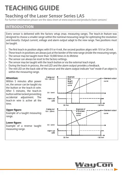
TEACHING GUIDETeaching of the Laser Sensor Series LASFor further information please see the data sheet at /products/laser-sensors/that the distance between sensor and target should be as small as possible. MR stands for the taught measurement S-TM-101618.52123.52605101520MR <4 mm MR 6 mmMR 8 mmMR 10 mm± L i n e a r i t y (μm )Measurement range (mm)1618,52123.526012345678MR <4 mmMR 6 mm MR 8 mm MR 10 mm R e s o l u t i o n (μm )Measurement range (mm)LAS-TM-10416426894120050100150200250300350400MR 2 mm MR 50 mm MR 104 mm± L i n e a r i t y (μm )Measurement range (mm)16426894120020406080100120140160MR 2 mm MR 25 mm MR 50 mm MR 75 mm MR 104 mmR e s o l u t i o n (μm )Measurement range (mm)LAS-TM-3005012520027535000.511.52MR <25 mm MR 150 mmMR 300 mm± L i n e a r i t y (m m )Measurement range (mm)5012520027535000.10.20.30.40.50.6MR <25 mm MR 75 mm MR 150 mm MR 225 mm MR 300 mmR e s o l u t i o n (m m )Measurement range (mm)LAS-TM-5005015025035045055000,511,522,533,54MR 10 mm MR 250 mmMR 500 mm± L i n e a r i t y (m m )Measurement range (mm)5015025035045055000.20.40.60.811.21.4MR 10 mm MR 250 mm MR 500 mmR e s o l u t i o n (m m )Measurement range (mm)that the distance between sensor and target should be as small as possible. MR stands for the taught measurement S-T5-403040506070010203040506070MR 2 mm MR 20 mmMR 40 mm± L i n e a r i t y (μm )Measurement range (mm)30405060700510********MR 2 mm MR 10 mm MR 20 mm MR 30 mm MR 40 mmR e s o l u t i o n (μm )Measurement range (mm)LAS-T5-100305580105130050100150200250MR 3 mm MR 50 mmMR 100 mm± L i n e a r i t y (μm )Measurement range (mm)30558010513001020304050607080MR 3 mm MR 25 mm MR 50 mm MR 75 mm MR 100 mmR e s o l u t i o n (μm )Measurement range (mm)LAS-T5-25050112.5175237.530000.20.40.60.811.2MR 5 mm MR 100 mm MR 250 mm± L i n e a r i t y (m m )Measurement range (mm)50112.5175237.530000.050.10.150.20.250.30.350.40.45MR 5 mm MR 50 mm MR 100 mm MR 175 mm MR 250 mmR e s o l u t i o n (m m )Measurement range (mm)LAS-T5-50010022535047560000.511.522.5MR 10 mm MR 250 mm MR 500 mm± L i n e a r i t y (m m )Measurement range (mm)10022535047560000.10.20.30.40.50.60.70.80.9MR 10 mm MR 100 mm MR 250 mm MR 375 mm MR 500 mmR e s o l u t i o n (m m )Measurement range (mm)LAS-T-800200400600800100000.20.40.60.811.21.41.61.822.2MR 16 mm MR 200 mmMR 400 mm MR 600 mm MR 800 mm ± L i n e a r i t y (m m )Measurement range (mm)200400600800100000.10.20.30.40.50.6MR 16 mm MR 200 mm MR 400 mm MR 600 mm MR 800 mmR e s o l u t i o n (m m )Measurement range (mm)When teaching the measurement range, it is recommended to always select the smallest possible range, because this way the resolution is increased and the linearity error decreased. Also keep in mind that the distance between sensor and target should be as small as possible. MR stands for the taught measurement range.LAS-TB-1050556030323436384042444648± L i n e a r i t y (µm )Measurement range (mm)50556010111213141516R e s o l u t i o n (µm )Measurement range (mm)LAS-TB-4060708090100405060708090100110120130MR 30 mm MR 40 mm± L i n e a r i t y (µm )Measurement range (mm)6070809010010152025303540MR 30 mm MR 40 mmR e s o l u t i o n (μm )Measurement range (mm)LAS-TB-1001001251501752000.10.150.20.250.30.350.40.450.5MR 75 mm MR 100 mm± L i n e a r i t y (m m )Measurement range (mm)1001251501752000.020.040.060.080.100.120.140.16MR 75 mm MR 100 mmR e s o l u t i o n (m m )Measurement range (mm)TEACHING BY TEACH LINELEGEND。
基恩士 GV系列激光传感器用户手册讲解

数字CMOS 激光传感器GV 系列使用手册为了获得最佳性能,请在使用传感器前阅读此手册。
请妥善保管此手册,以便随时查阅。
注显示值表明了距离的指导方针且不应在精确测量应用中使用。
GV 系列的安全信息•本产品仅可用于检测物体。
切勿将本产品用于保护人体或人体的任何部分。
警告•本产品并非防爆产品。
切勿在危险场所或有可能爆炸的环境中使用本产品。
激光产品的安全注意事项* FDA(CDRH )的激光分级是根据IEC60825-1进行的,符合激光公告第50号的要求。
对于激光的安全措施■发射激光辐射指示灯在打开电源开关并且发出激光光束之后,发射激光辐射指示灯就亮起。
传感器放大器感测头■激光发射停止输入当在紫色线上信号输入达20ms 或更长时间时,激光发射停止。
激光光束在取消信号输入后约20ms 内发射。
这种控制输出功能根据检测值来运行,即使当输入激光发射停止的时候。
■激光警告标签下图表明了GV 系列的激光警告标签的类型和位置。
GV-H45(L/H130(LGV-H450(L/H1000(L警告标签*警告标签** GV-H45L/H130L/H450L/H1000L中不附带。
●发射孔标签●FDA (CDRH )警告标签(等级)警告标签。
●IEC 警告/说明标记(等级 2)只有等级2的激光产品上会有IEC 警告/说明标签。
在美国以外的国家或地区使用本产品时,请使用产品包装中包含的IEC 警告/说明标记。
此时可以将其粘贴在已经粘贴在本产品上的FDA(CDRH )警告标签上。
检查包装中物品在使用本模块前,检查您所购买型号的包装中是否包括以下部件和设备。
■传感器放大器GV-21/GV-21P(主模块)GV-22/GV-22P(扩展模块)放大器x1放大器x1使用手册 x1■感测头GV-H45(L/H130(LGV-H450(L/H1000(L感测头x1绝缘板x1安装支架x1绝缘板X 1x1主机板螺帽x1安装支架M3 x L30 x1螺丝x2主机板螺帽激光警告标签*x1M4 x L35 螺丝x2激光警告标签*x1* GV-H45L/H130L/H450L/H1000L中不附带。
微型极化反射激光传感器数据手册说明书

DatasheetMiniature Polarized Retroreflective Laser Sensors•Visible Class 1 laser•Narrow effective beam provides small-object detection and precise position control•Crosstalk rejection algorithm protects against optical disturbance from adjacent sensors•Excellent optical performance throughout sensing range, even close up•10 V dc to 30 V dc operation, with complementary (SPDT) NPN or PNP outputs, dependingon model•Bright LED operating status indicators are visible from 360°•Compact, rugged sealed housing, protected circuitry•Mounting versatility – popular 18 mm threaded barrel or side-mount•Choose 2 m (6.5 ft) or 9 m (30 ft) cable or one of four QD optionsExcellent for applications where high sensing power and small beam size are important. Uses a specialfilter to polarize the emitted light, filtering out unwanted reflections from shiny objects.WARNING:•Do not use this device for personnel protection•Using this device for personnel protection could result in serious injury or death.•This device does not include the self-checking redundant circuitry necessary to allow its use inpersonnel safety applications. A device failure or malfunction can cause either an energized (on) or de-energized (off) output condition.ModelsStandard 2 m (6.5 ft) cable models are listed. To order a 9 m (30 ft) cable model, add the suffix “W/30” to the model number (for example, QS18VN6LLP W/30).To order QD models with a 4-pin integral Euro-style QD, add suffix “Q8” (for example, QS18VN6LLPQ8); to order a 4-pin Euro-style 150 mm (6 in.) pigtail QD, add suffix “Q5” (for example, QS18VN6LLPQ5); to order a 4-pin integral Pico-style QD, add suffix “Q7”(for example, QS18VN6LLPQ7); to order a 4-pin Pico-style 150 mm (6 in.) pigtail QD, add suffix “Q” (for example, QS18VN6LLPQ). Models with a QD connector requires a mating cable.Installation NotesConventional retroreflective photoelectric sensors are extremely easy to align. Beam angles are wide, and retro targets are forgiving to the light beam’s angle of incidence. The beam of this laser sensor is very narrow, compared with the beam of most retro sensors. As the figure indicates, the effect of angular misalignment can be dramatic. Alignment is critical because the beam may miss the retroreflective target unless the target is large.For example, with one BRT-51X51BM mounted at a distance of 6 m (20 ft) from the sensor, one degree of angular misalignment will cause the center of the laser beam to miss the center of the target by 100 mm (4 inches).WORLD-BEAM® QS18LLP SeriesOriginal Document118900 Rev. J5 May 2022118900Alignment TipWhen using a small retroreflective target at medium or long range, it is often useful to temporarily attach (or suspend) a strip ofretroreflective tape (for example, BRT-THG-2) along a line that intersects the actual target. The visible red laser beam is easily seen in normal room lighting on such tape. Sight along the beam toward the target (from behind the sensor). Move the sensor to sweep the laser beam back and forth across the retro tape strip. Use the tape strip to guide the beam onto the target.Consider using sensor mounting bracket model SMB18SF or SMB3018SC. A swivel bracket can simplify multiple-axis alignment.Alignment is complete when the visible image is centered on the retro target. The perpendicularity of the laser beam to the face of the retro target is forgiving, just as it is with a conventional retroreflective sensor.Effective Beam SizeUnlike conventional retroreflective sensors, the retroreflective laser has the ability to sense relatively small profiles. The table indicates the diameter of the smallest opaque rod which will reliably break the laser beam at several sensor-to-object distances.These minimum object sizes were measured with the sensor aligned to a BRT-51X51BM reflector and with the sensor set for an excess gain of about 10X. Flooding effects are possible when the gain is much higher. This means that sensor gain may have to be reduced in some situations in order to reliably detect these minimum object sizes.CAUTION:•Never stare directly into the sensor lens.•Laser light can damage your eyes.•Avoid placing any mirror-like object in the beam. Never use a mirror as a retroreflective target.Note that the shape of the beam is elliptical. The minimum object sizes listed assume passage of the rod across the major diameter of the ellipse (worst case). It may be possible to detect objects smaller than the sizes listed if the direction in which the objects pass through the beam can be controlled.Retroreflector RecommendationsBRT-51X51BM recommended for beam-block applications up to 10 m range. The reflector is included with the sensor. See Accessories on page 5 for information about ordering replacements or other reflector options.Note: When sensing objects with specular reflections, use the sensor’s side-mounting option to optimize sensing performance. - Tel: + 1 888 373 6767P/N 118900 Rev. JWiring DiagramsCabled wiring diagrams are shown.Quick disconnect wiring diagrams are functionally identical.NPN (Sinking) OutputsPNP (Sourcing) Outputs–+Wiring Key1 = Brown2 = White3 = Blue4 = BlackSpecificationsSupply Voltage10 V DC to 30 V DC (10% maximum ripple) at less than 15 mA, exclusive of load Sensing BeamVisible red laser , 650 nmLaser CharacteristicsWavelength: 650 nm visible red Class 1 laser Pulse Width: 7 microseconds Rep Rate: 130 microsecondsAverage Output Power: 0.065 mWSupply Protection CircuitryProtected against reverse polarity and transient voltagesOutput ConfigurationSolid-state complementary (SPDT): NPN or PNP (current sinking or sourcing), depending on model;Rating: 100 mA maximum eh output at 25 °C Off-state leakage current:NPN: less than 200 µA at 30 V DC (See Application Note 1)PNP: less than 10 µA at 30 V DC ON-state saturation voltage:NPN: less than 1.6 V at 100 mA PNP: less than 3.0 V at 100 mAOutput Protection CircuitryProtected against false pulse on power-up and continuous overload or short circuit of outputs Output ResponseNote: 200 millisecond delay on power-up; outputs do not conduct during this time700 microseconds ON/OFF Repeatability130 microseconds Sensing Hysteresis 12% of range typicalAdjustmentsSingle-turn sensitivity (Gain) adjustment potentiometerIndicators2 LED indicators on sensor top:Green solid: Power on Amber solid: Light sensedAmber flashing: Marginal excess gain (1 to 1.5x excess gain)ConstructionABS housing, rylic lens cover, 3 mm mounting hardware includedConnections2 m (6.5 ft) 4-wire PVC cable, 9 m (30 ft) 4-wire PVC cable, 4-pin Pico-style or Euro-style QD, 4-pin Pico-style or Euro-style 150 mm (6 in) pigtail QD,depending on model Laser ClassificationClass 1 laser product; Complies with IEC 60825-1:2014 and 21 CFR1040.10, except for deviations pursuant to Laser Notice 56, dated May 8,2019Operating ConditionsRelative Humidity: 95% at +50 °C maximum relative humidity (non-condensing)Temperature: –10 °C to 50 °C (14 °F to 122 °F)Application NotesNPN off-state leakage current is < 200 µA for load resistances > 3 kΩ or optically isolated loads. For load current of 100 mA, leakage is < 1% of load current.CertificationsBanner Engineering Europe Park Lane, Culliganlaan 2F bus 3, 1831 Diegem,BELGIUMTurck Banner LTD Blenheim House, Blenheim Court,Wickford, Essex SS11 8YT,Great BritainRequired Overcurrent ProtectionWARNING: Electrical connections must bemade by qualified personnel in accordance with local and national electrical codes and regulations.Overcurrent protection is required to be provided by end product application per the supplied table.Overcurrent protection may be provided with external fusing or via Current Limiting, Class 2 Power Supply.Supply wiring leads < 24 AWG shall not be spliced.P/N 118900 Rev. J - Tel: + 1 888 373 67673DimensionsCabled Models3 mm (0.12")(0.67")Pico-Style QD ModelsPigtail4-pinPico-Style QDEuro-Style QD ModelsPigtail4-pin Euro-Style QDLocknut (included with all models)Washer (included with all models)Ø 17.8 mm(0.70")(0.94")M3 Hardware Packet Contents:• 2 – M3 x 0.5 x 20 mm SS Screw • 2 – M3 x 0.5 SS Hex Nut • 2 – M3 SS WasherDescription of Class 1 LasersClass 1 lasers are lasers that are safe under reasonably foreseeable conditions of operation, including the use of optical instruments for intrabeam viewing.Reference IEC 60825-1:2014CAUTION:•Return defective units to the manufacturer.•Use of controls or adjustments or performance of procedures otherthan those specified herein may result in hazardous radiation exposure.•Do not attempt to disassemble this sensor for repair. A defective unitmust be returned to the manufacturer.For Safe Laser Use (Class 1 or Class 2):•Do not stare at the laser.•Do not point the laser at a person’s eye.•Mount open laser beam paths either above or below eye level, where practical.•Terminate the beam emitted by the laser product at the end of its useful path. - Tel: + 1 888 373 6767P/N 118900 Rev. JAccessoriesP/N 118900 Rev. J - Tel: + 1 888 373 67675Brackets - Tel: + 1 888 373 6767P/N 118900 Rev. JSMB3018SC•18 mm swivel side or barrel-mount bracket•Black reinforcedthermoplastic polyester•Stainless steel swivellocking hardware includedHole center spacing: A = 50.8Hole size: A = ø 7.0, B = ø 18.0Retroreflective TargetsBanner offers a wide selection of high-quality retroreflective targets. Go to for complete information.Note: Polarized sensors require corner cube type retroreflective targets only. Reflectivity factor when comparedwith the standard BRT-3 reflector.BRT-51X51BM•Square, acrylic target•Reflectivity Factor: 1.5•Temperature: –20 °C to +50 °C (–4 °F to +122 °F)•Micro-prism geometry•Optional brackets are available•Approximate size: 51 mm × 51 mm100(4.0")(40")(400")(4000")(0.4")1000EXCESSGAINDISTANCEBRT-35X35BM•Square, acrylic target•Reflectivity Factor: 1.2•Temperature:-20 °C to +60 °C(-4 °F to +140 °F)•Micro-prism geometry•Approximate size:35 mm × 35 mmBanner Engineering Corp. Limited WarrantyBanner Engineering Corp. warrants its products to be free from defects in material and workmanship for one year following the date of shipment. Banner Engineering Corp. will repair or replace, free of charge, any product of its manufacture which, at the time it is returned to the factory, is found to have been defective during the warranty period. This warranty does not cover damage or liability for misuse, abuse, or the improper application or installation of the Banner product.THIS LIMITED WARRANTY IS EXCLUSIVE AND IN LIEU OF ALL OTHER WARRANTIES WHETHER EXPRESS OR IMPLIED (INCLUDING, WITHOUT LIMITATION, ANY WARRANTY OF MERCHANTABILITY OR FITNESS FOR A PARTICULAR PURPOSE), AND WHETHER ARISING UNDER COURSE OF PERFORMANCE, COURSE OF DEALING OR TRADE USAGE.This Warranty is exclusive and limited to repair or, at the discretion of Banner Engineering Corp., replacement. IN NO EVENT SHALL BANNER ENGINEERING CORP. BE LIABLE TO BUYER OR ANY OTHER PERSON OR ENTITY FOR ANY EXTRA COSTS, EXPENSES, LOSSES, LOSS OF PROFITS, OR ANY INCIDENTAL, CONSEQUENTIAL OR SPECIAL DAMAGES RESULTING FROM ANY PRODUCT DEFECT OR FROM THE USE OR INABILITY TO USE THE PRODUCT, WHETHER ARISING IN CONTRACT OR WARRANTY, STATUTE, TORT, STRICT LIABILITY, NEGLIGENCE, OR OTHERWISE.Banner Engineering Corp. reserves the right to change, modify or improve the design of the product without assuming any obligations or liabilities relating to any product previously manufactured by Banner Engineering Corp. Any misuse, abuse, or improper application or installation of this product or use of the product for personal protection applications when the product is identified as not intended for such purposes will void the product warranty. Any modifications to this product without prior express approval by Banner Engineering Corp will void the product warranties. All specifications published in this document are subject to change; Banner reserves the right to modify product specifications or update documentation at any time. Specifications and product information in English supersede that which is provided in any other language. For the most recent version of any documentation, refer to:.For patent information, see /patents.© Banner Engineering Corp. All rights reserved。
LPS系列激光测距传感器使用手册

本激光测距传感器的数据输出为标准的串行 RS-232 接口。需要配套的设备来接收数据,
9
激光测距传感器和计算机的连接图
10
单片机 或DSP
Rx CPU GND Tx
Tx GND Rx GND Vcc
激光测距传感器
8-24V直流 稳压电源
激光测距传感器和单片机或 DSP 的连接图
仪器安装
激光测距传感器与数据接口的组装: 把通讯连接线与计算机或工业控制机的串口 DB9 连接。 把电源线、串口连接线按照下表连接。
4.
05 C1 41 00 41
这样
的一串串数据输出。再点下串口软件右下方的“HEX 显示”就能看到 001.16 样一串串的数据,001.16 表示 1.16 米。 5. 6. 如果输出的数据是
这
error 表示测量失败。
其它操作可按串行通信协议定义进行操作。
串行通信协议定义如下 : 05 C1 23 00 23 是开始测量; 05 C1 24 00 24 是停止测量; 05 C1 22 01 01 24 是 1HZ 测量; 05 C1 22 01 02 25 是 10HZ 测量 ;
LPS 系列激光测距传感器是一种功能强大的测量精确、无接触式的工业用距离测量设 备,它可广泛地被集成用于各种工业用途的控制和监测系统上。使用图例如下:
被测距离 目 激光测距传感器 标
4
LPS 系列激光测距传感器是一款使用方便的工业应用激光测距仪表, 特别为交通、 炼钢、
仓储、建筑、码头等需要自动进行距离和位置控制的应用而设计研发,具有很高地实用性。
15
05 C1 22 01 03 26 是 20HZ 测量 ; 05 C1 22 01 04 27 是 50HZ 测量 ; 05 C1 22 01 05 28 是 100HZ 测量; 05 C1 12 01 55 68 是开激光指示灯; 05 C1 12 01 AA BD 是关激光指示灯; 05 C1 41 00 41 是 FLOAT 型十进制输出; 05 C1 40 00 40 是 FLOAT 型十六进制格式输出;
KEYENCE LV 系列通用数字激光传感器 说明书

在棒状 LED 监视器 上显示多余增益
■ LV-H32
通过旋转焦点环调节光束点的大小。 调节完成后,用焦点锁定螺丝固定。
发射器 焦点环
接收器
K
LOC
焦点锁
■ LV-H37/H47
■ LV-H41/H42
发射器 接收器
发射器 接收器
■ LV-H51/H52
■ LV-H35/H62/H67
发射器 接收器
CAUTION
LASER RADIATIONDO NOT STARE INTO BEAM.
SEMICONDUCTOR LASER 650nm
MAXIMUM OUTPUT
3mW
PULSE DURATION
3.5 s
CLASS II LASER PRODUCT
已贴上 FDA 警告标签
1-3-14,Higashi-Nakajima,Higashi -Yodogawa-ku,Osaka,533-8555, JAPAN
s
THIS 21
PCRFORD1U0C4L0TA.D1SC0OCEOSRANAEMMOMUNRAPTIPCDATXLUSODIICMILTNOIE1LSAAUDA0SETRNMUS4IEOCDS0WOTNU.OIUI1RNI-ITRT1ALTPHTAOLUISAOTBESNEERRAPMR.O6D5U0Cn3Tmm3.W5
s
激光等级Ⅱ警告标签
THIS 21
PCRFORD1U0C4L0TA.D1SC0OCEOSRANEAMMOMUNRAPTIPCADTXLUSODIICMILTNOIE1LSAAUDA0SETRNMUS4IEOCDS0WOTNU.OIUI1RIN-IRTT1ALTPHTAOLUISAOTBESNEERRAPMR.O6D5U0Cn3Tmm3.W5
潘基Panasonic LS-401-C2数字激光传感器说明书
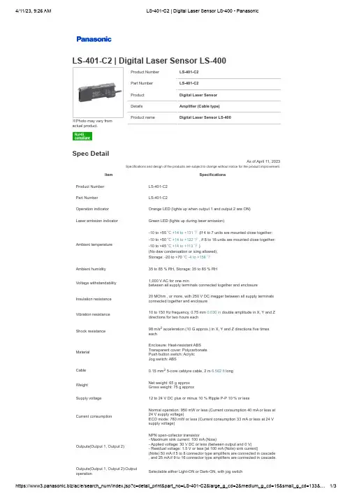
※Photo may vary from actual product.Product Number LS-401-C2Part Number LS-401-C2Product Digital Laser Sensor Details Amplifier (Cable type)Product nameDigital Laser Sensor LS-400LS-401-C2 | Digital Laser Sensor LS-400Spec DetailAs of April 11, 2023Specifications and design of the products are subject to change without notice for the product improvement.ItemSpecificationsProduct Number LS-401-C2Part Number LS-401-C2Operation indicator Orange LED (lights up when output 1 and output 2 are ON)Laser emission indicatorGreen LED (lights up during laser emission)Ambient temperature-10 to +55 ℃ +14 to +131 ℉ (If 4 to 7 units are mounted close together:-10 to +50 ℃ +14 to +122 ℉ , if 8 to 16 units are mounted close together:-10 to +45 ℃ +14 to +113 ℉ )(No dew condensation or icing allowed),Storage: -20 to +70 ℃ -4 to +158 ℉Ambient humidity 35 to 85 % RH, Storage: 35 to 85 % RHVoltage withstandability1,000 V AC for one min.between all supply terminals connected together and enclosureInsulation resistance20 MOhm , or more, with 250 V DC megger between all supply terminals connected together and enclosureVibration resistance10 to 150 Hz frequency, 0.75 mm 0.030 in double amplitude in X, Y and Z directions for two hours eachShock resistance98 m/s 2 acceleration (10 G approx.) in X, Y and Z directions five times eachMaterialEnclosure: Heat-resistant ABS Transparent cover: Polycarbonate Push button switch: Acrylic Jog switch: ABSCable0.15 mm 2 5-core cabtyre cable, 2 m 6.562 ft long Weight Net weight: 65 g approx Gross weight: 75 g approxSupply voltage12 to 24 V DC plus or minus 10 % Ripple P-P 10 % or lessCurrent consumptionNormal operation: 950 mW or less (Current consumption 40 mA or less at 24 V supply voltage)ECO mode: 780 mW or less (Current consumption 33 mA or less at 24 V supply voltage)Outputs(Output 1, Output 2)NPN open-collector transistor- Maximum sink current: 100 mA (Note)- Applied voltage: 30 V DC or less (between output and 0 V)- Residual voltage: 1.5 V or less [at 100 mA (Note) sink current](Note) 50 mA if 5 to 8 connector type amplifiers are connected in cascade , and 25 mA if 9 to 16 connector type amplifiers are connected in cascade.Outputs(Output 1, Output 2):Output operationSelectable either Light-ON or Dark-ON, with jog switchProduct Number Part NumberProductDetails Product name ProductNumberPart NumberProductDetailsProductnameProductNumberPart NumberProductDetailsProductnameProduct Number Part NumberProductDetails Product name ProductNumberPart NumberProductDetailsProductnameProductNumberPart NumberProductDetailsProductnameProduct Number Part Number ProductNumberPart NumberProductNumberPart NumberOutputs(Output 1, Output 2):Short-circuit protectionIncorporatedResponse time 80 micro s or less (H-SP), 150 micro s or less (FAST), 500 micro s or less (STD), 4 ms or less (U-LG) selectable with jog switchExternal input(Laser emission halt Full-auto teaching / Limit teaching)NPN non-contact input- Signal conditionHigh: +5 V to +V DC or open, Low: 0 to +2 V DC (source current 0.5 mA or less)- Input impedance: 10 kOhm approx.Select indicator Yellow LED(lights up when either output 1 or output 2 is selected)MODE indicator RUN: Green LEDTEACH, L/D, TIMER, CUST, PRO: Yellow LEDDigital display 4 digit (green) + 4 digit (red) LED displaySensitivity setting Normal mode: 2-level teaching / Limit teaching / Full-auto teaching / Manual adjustmentWindow comparator mode: Teaching (1-level, 2-level, 3-level) / Manual adjustmentHysteresis mode: Teaching (1-level, 2-level, 3-level) / Manual adjustment Differential mode: 5-level settingsFine sensitivity adjustment function IncorporatedTimer function Incorporated with variable ON-delay / OFF-delay / ONE SHOT timer, switchable either effective or ineffective.Timer function:Time 1 to 9,999 msAutomatic Interference prevention function Incorporated[Up to four sets of sensor heads can be mounted close together. (However, disabled when in H-SP mode)]Cable extension Extension up to total 100 m 328.084 ft is possible with 0.3 mm 2, or more,cable. AccessoriesProduct Connector for amplifierProduct name ConnectorProductBank SelectionUnitDetails NPN inputProductnameBank SelectionUnit FX-CHProductBank SelectionUnitDetails PNP inputProductnameBank SelectionUnit FX-CHProduct Number Part NumberProductProduct name ProductNumberPart NumberProductProductnameProductNumberPart NumberProductProductname© Panasonic Industry Co., Ltd.。
激光传感器技术手册
4.3.1 对接 .............................................................................................................. 15 4.3.2 V 型坡口 ...................................................................................................... 15 4.3.3 搭接 ............................................................................................................... 16 4.3.4 角接 .............................................................................................................. 16 4.3.5 外侧角接 ...................................................................................................... 16 5. 控制系统.................................................................................................... 17 5.1 控制器 ................................................................................................................. 17 5.1.1 基本规格 ...................................................................................................... 17 5.1.2 SAPEII 板..................................................................................................... 18 5.1.3 接口板 .......................................................................................................... 18 5.1.4 放大器(可选) ............................................................................................... 18 5.2 手控盒 ................................................................................................................. 18 5.2.1 描述 .............................................................................................................. 18 5.2.2 技术数据 ...................................................................................................... 19 5.2.3 功能 ........................................................................................................ 19 5.3 接口 ................................................................................................................ 20 5.3.1 外部控制 ...................................................................................................... 20 5.3.2 滑架 ........................................................................................................ 21 5.3.3 视频监控器 (可选) ................................................................................ 22 5.4 Laser Probe Tools(工具软件) ............................................................................. 23 5.4.1 概述 .............................................................................................................. 23 5.4.2 许可证 .......................................................................................................... 23 5.4.3 安装 .............................................................................................................. 23 5.4.4 焊缝设置 ...................................................................................................... 24
激光传感器使用说明书
光透过型激光传感器IG 系列操作手册在使用 IG 系列 CCD 光透过型激光传感器之前,请仔细阅读本操作手册。
阅读之后,请妥善保管本手册,以便随时查阅。
IG系列的安全信息⏹一般注意事项•在启动时和操作期间,请务必监视本产品的功能与性能,并确认是否正常工作。
•建议您采取有效的安全措施,以避免万一发生问题时造成任何损坏。
•如果按照规格中未描述的任何方式改装或使用产品,则产品的功能与性能不予保证。
•请勿将本产品用于保护人体。
•请勿使本设备经受剧烈的温度变化,否则可能会发生产品故障。
*此分类基于 IEC60825-1 标准,该标准符合 FDA 的 Laser Notice No. 50(50 号激光通知)(CDRH)。
⏹激光发射停止输入激活激光发射停止输入之后,可以通过将外部输入设为 ON(2 ms 或更长时间)来停止激光发射。
外部输入为 ON 时,激光发射将一直处于停止状态。
外部输入设为 OFF 时,激光将在 2 ms 内发射出来。
有关激光发射停止输入期间不连续输出或模拟输出条件的详细信息,请参照“用户手册”的“11. 外部输入”。
异常情况使用注意事项⏹安装环境为了确保安全使用本产品,请勿将本产品安装在以下位置。
•湿度高、多尘以及通风不良的位置。
•装置会受到阳光直射的高温位置。
•存在腐蚀性气体或易燃气体的位置。
•本装置可能会直接受到振动或冲击的位置。
•水、油或化学品可能会溅到本装置上的位置。
•容易产生静电的位置。
⏹脏污的影响•灰尘、水、油等可能会导致发生测量误差。
•使用吹气装置除去粘在发射器与接收器上的脏污;对于严重的脏污,请使用蘸有酒精的软布进行擦拭。
如果发射器与接收器有划痕,则可能会发生测量误差。
•使用吹气装置除去附着在目标上的脏污,或是将脏污擦拭掉。
•如果脏污在测量范围内漂浮,请采取充分的措施,如安装防尘盖或是进行吹气。
⏹抗噪防护将本装置安装在噪声源(如发电机或高压线)附近时,可能会发生操作误差或产品故障。
D-系列激光测距传感器 技术参考手册说明书
激光测距传感器DPE-10-500 | DPE-30-500 DEN-10-500 | DEH-30-500DAN-10-150 | DAN-30-150 | DAE-10-050DBN-50-050技术参考手册V1.1016.03.2020SWISS PRECISIONSWISS PRECISION1文档范围 (3)2安全指令 (3)2.1符号的解释 (3)2.2允许使用的用途 (4)2.3禁止使用/限制使用 (4)2.4职责范围 (5)2.5使用中的危害 (5)2.6激光分类 (6)2.7激光规范 (6)2.8电磁兼容性(EMC) (7)2.9生产标准 (7)2.10处理 (7)2.11标签 (7)2.13服务 (8)3介绍 (9)3.1产品标识 (10)3.2组件 (10)3.3有效性 (11)4技术数据 (12)4.1规范 (12)4.2物理尺寸 (14)4.3测量精度定义 (14)5电气部分 (15)5.1电源 (15)5.2复位按钮 (16)5.3 LED状态 (17)5.4数字输出 (17)5.5数字输入 (18)5.6模拟输出 (18)5.7 RS - 232接口 (20)5.8 RS-422 / RS-485接口 (21)5.9 SSI接口 (23)5.10 USB接口 (25)5.11工业以太网接口 (26)6配置 (28)6.1配置过程 (28)6.2操作模式 (30)6.3测量特征 (31)6.4数据输出 (32)7操作 (37)7.1测量概述 (37)7.2安装 (37)7.3测量性能的影响 (38)7.4防止测量错误 (39)7.5激光寿命 (40)1.文档范围7.7应用程序示例/说明 ................................................................................................................................................................................................. 40 8命令集 (41)8.1普通 .......................................................................................................................................................................................................................... 41 8.2操作命令 .................................................................................................................................................................................................................. 41 8.3配置命令 .................................................................................................................................................................................................................. 45 8.4扩展配置命令 .......................................................................................................................................................................................................... 51 8.5信息的命令 .............................................................................................................................................................................................................. 53 8.6错误代码 .................................................................................................................................................................................................................. 55 9常见问题(FAQ’s) ................................................................................................................................................................................................................ 57 10词汇表 ............................................................................................................................................................................................................................... 57 11修订历史 (57)1文档范围本文介绍了Dimetix D 系列激光距离传感器。
激光位移传感器操作手册说明书
激光位移传感器操作手册V2.0目录第1章:产品概要......................................................................... 1-11.1 包装内容 ......................................................................................... 1-11.2 各部件名称及功能........................................................................... 1-21.3 安装................................................................................................. 1-3 第2章:设定与测量 ..................................................................... 2-1 第3章:软件操作......................................................................... 3-13.1 通信设置 ......................................................................................... 3-13.2 位置读取与归零设定 ....................................................................... 3-2 第4章:通讯指令......................................................................... 4-14.1 通讯参数列表 .................................................................................. 4-14.2 通讯协议 ......................................................................................... 4-4 第5章:产品规格......................................................................... 5-1 第6章:安全注意事项.................................................................. 6-1 第7章:保固 ................................................................................ 7-1版本更新历程激光位移计操作手册V2.0版本更新历程版本更新日期V1.0 第一版发行2018/09/03V2.0 新增「反应速度设定」与「中值滤波器设定」功能说明与通讯地址设定方式。