数电课程设计二进制密码锁的设计
数电电子密码锁课程设计
数电电子密码锁课程设计一、课程目标知识目标:1. 理解数字电路基础知识,掌握电子密码锁的基本原理;2. 学会使用逻辑门、触发器等基本数字电路元件,并应用于电子密码锁的设计;3. 掌握电子密码锁的编码与解码技术,了解其安全性分析。
技能目标:1. 能够运用所学知识,设计并搭建一个简单的电子密码锁电路;2. 学会使用相关软件(如Multisim等)进行电路仿真,提高实际操作能力;3. 培养学生团队协作、动手实践和问题解决能力。
情感态度价值观目标:1. 培养学生对数字电路和电子技术的兴趣,激发创新意识;2. 增强学生的信息安全意识,了解密码学在生活中的应用;3. 树立正确的价值观,认识到科学技术对社会发展的积极作用。
课程性质:本课程为实践性较强的课程,结合理论知识,培养学生的实际操作能力和团队协作能力。
学生特点:学生在本年级已具备一定的数字电路基础,对电子技术有一定了解,但实际操作能力有待提高。
教学要求:教师应注重理论与实践相结合,关注学生个体差异,提供个性化指导,确保学生在课程中学有所获。
通过课程学习,使学生在知识、技能和情感态度价值观方面均取得具体的学习成果。
二、教学内容1. 数字电路基础知识回顾:逻辑门、触发器、计数器等基本元件的工作原理与应用;- 教材章节:第一章 数字逻辑电路基础2. 电子密码锁原理讲解:密码锁的工作流程、安全性分析;- 教材章节:第三章 安全电子密码锁3. 电子密码锁电路设计:使用逻辑门、触发器等元件设计密码锁电路;- 教材章节:第二章 组合逻辑电路设计4. 电路仿真与实验操作:利用Multisim软件进行电路仿真,实际搭建电子密码锁;- 教材章节:第四章 电路仿真与实验5. 编码与解码技术:了解常见编码方式,学习密码锁的解码技巧;- 教材章节:第三章 安全电子密码锁6. 团队协作与项目实施:分组进行项目实践,培养学生的团队协作能力和实际操作能力;- 教材章节:附录 实践项目指导教学进度安排:第一周:回顾数字电路基础知识,学习电子密码锁原理;第二周:设计电子密码锁电路,进行电路仿真;第三周:实际操作,搭建电子密码锁,学习编码与解码技术;第四周:团队协作,完成项目实施,进行成果展示与评价。
数字系统课程设计密码锁

数字系统课程设计密码锁一、教学目标本课程旨在通过数字系统课程设计密码锁的学习,让学生掌握数字系统的基本概念,了解密码锁的工作原理和设计方法。
在知识目标方面,学生应了解数字系统的组成、工作原理以及各种编码方式。
在技能目标方面,学生应掌握数字电路的设计方法,能够独立完成密码锁的设计与实现。
在情感态度价值观目标方面,学生应培养对数字技术的兴趣和好奇心,增强创新意识和团队协作能力。
二、教学内容本课程的教学内容主要包括数字系统的基本概念、密码锁的工作原理、数字电路的设计方法等。
具体包括以下几个方面:1.数字系统的基本概念:数字系统的组成、工作原理、数字逻辑电路的分类及其特点。
2.密码锁的工作原理:密码锁的分类、工作原理及其安全性分析。
3.数字电路的设计方法:组合逻辑电路、时序逻辑电路的设计方法及其应用。
4.编码方式:二进制编码、格雷码、BCD码等编码方式的特点及应用。
三、教学方法为了提高学生的学习兴趣和主动性,本课程将采用多种教学方法,如讲授法、讨论法、案例分析法、实验法等。
1.讲授法:通过讲解数字系统的基本概念、密码锁的工作原理等理论知识,使学生掌握相关概念和原理。
2.讨论法:学生针对数字电路设计方法、密码锁安全性等问题进行讨论,培养学生的思考能力和团队协作精神。
3.案例分析法:通过分析实际案例,使学生了解数字电路在实际应用中的工作原理和设计方法。
4.实验法:安排学生进行数字电路的设计与实现,提高学生的动手能力和实际操作技能。
四、教学资源为了支持教学内容和教学方法的实施,丰富学生的学习体验,我们将选择和准备以下教学资源:1.教材:选用国内权威出版的数字系统及相关课程教材,为学生提供系统的理论知识。
2.参考书:推荐学生阅读相关领域的经典著作,拓宽知识面。
3.多媒体资料:制作课件、教学视频等,以图文并茂的形式展示教学内容,提高学生的学习兴趣。
4.实验设备:准备数字电路实验箱、编程器等实验设备,为学生提供实践操作的机会。
电子电路课程设计密码锁(满分实验报告)解析

密码锁设计报告摘要:本系统是由键盘和报警系统所组成的密码锁。
系统完成键盘输入、开锁、超时报警、输入位数显示、错误密码报警、复位等数字密码锁的基本功能。
关键字:数字密码锁 GAL16V8 28C64 解锁与报警1目录:一、系统结构与技术指标1、系统功能要求 (4)2、性能和电气指标 (5)3、设计条件 (5)二、整体方案设计1、密码设定 (6)2、密码判断 (6)3、密码录入和判断结果显示 (6)4、系统工作原理框面 (7)三、单元电路设计1、键盘录入和编码电路图 (8)2、地址计数和存储电路 (12)3、密码锁存与比较电路 (12)24、判决与结果显示电路 (14)5、延时电路 (15)6、复位 (17)7、整机电路图 (19)8、元件清单 (19)四、程序清单1、第一片GAL (21)2、第二片GAL (23)五、测试与调整1、单元电路测试 (25)2、整体指标测试 (26)3、测试结果 (26)六、设计总结1、设计任务完成情况 (27)2、问题及改进 (27)3、心得体会 (28)3一、系统结构与技术指标1.系统功能要求密码锁:用数字键方式输入开锁密码,输入密码时开锁;如果输入密码有误或者输入时间过长,则发出警报。
密码锁的系统结构框图如下图所示,其中数字键盘用于输入密码,密码锁用于判断密码的正误,也可用于修改密码。
开锁LED1亮表示输入密码正确并开锁,报警LED2亮表示密码有误或者输入时间超时。
开锁green 键盘密码锁错误red42.性能和电气指标2.1 开锁密码为8位十进制数字,由按键输入,按“确认”键后,输入的数字有效。
2.2 输入的8位数字与预设的密码相同时开锁,用绿灯亮,红灯灭表示。
数据有误时或输入的密码时间过长即报警,红灯亮。
2.3 输入的数字间隔时间小于或等于15s。
超过时限则报警,同时电子锁复位。
2.4 具有手动、自动复位功能。
3. 设计条件3.1 电源条件:稳压电源提供+5V电压。
数字逻辑电路课程设计-电子密码锁
数字逻辑电路课程计课题:电子密码锁姓名:班级:学号:成绩:指导教师:开课时间:2014-2015学年第2学期2007年 6 月 20日电子密码锁摘要:采用逻辑门电路设计电子密码锁,阐述了其工作原理,给出了具体的电路原理图。
该密码锁具有密码预置功能,保密性强,误码报警,并且报警时间可以设定,同时用数码管显示出报警时间。
密码正确时驱动继电器控制开锁指示灯,误码时报警信号由蜂鸣器发出,声音为间歇式鸣笛。
采用自行设计的5V稳压电源供电,具有耗电省等特点。
当密码正确时密码锁可以被打开,绿色二极管亮代表密码正确,锁可以打开。
密码不正确时,红色二极管被点亮,同时蜂鸣器鸣笛5秒,数码管显示5秒计时;计时结束时,20秒计时开始。
关键词:电子密码锁;数字电路;预置密码;误码报警Using logic gate design of electronic combination lock, this paper expounds its working principle, gives the specific circuit principle diagram of the combination lock with password preset function, strong confidentiality, error alarm, and alarm time can be set, at the same time using digital tube display the alarm time. Password correctly drive relay control lamp, when the error alarm signal by a buzzer, voice for intermittent ing self-designed 5 v regulated power supply, has the characteristics of power saving electricity. When the correct password combination lock can be opened, the green led light on behalf of the correct password, the lock can be opened. Password is not correct, the red leds lit up, at the same time a buzzer honking 5 seconds, the digital tube display 5 seconds time, at the end of the timing, 20 seconds timer starts.Keywords: electronic password ,combination lock,digital circuit preset ,Error alarm目录1、设计背景 (4)2、设计方案 (5)2.1原理框图 (5)2.2总体思想 (5)3、方案实施 (7)3.1.1密码输入 (7)3.1.2密码存储 (8)3.1.3比较电路 (8)3.1.4 5秒计时器 (9)3.1.5 20秒计时器 (10)3.2电路仿真 (11)4、结果与结论 (12)5、收获与致谢 (14)6、参考文献 (15)1、设计背景1.1背景及其发展前景随着人们生活水平的提高和安全意识的加强,对安全的要求也就越来越高。
数电综合设计 电子密码锁的设计
昆明理工大学数字电路与系统课程设计报告题目:电子密码锁的设计学院:理学院专业班级:姓名:学号:指导教师:完成时间:201 年5月26日目录目录 (1)1、前言 (2)2.总体方案设计 (2)2.1 设计目的 (2)2.2 技术指标 (2)2.3 方案框图 (2)3. 单元模块设计 (3)3.1.1 密码设置模块设计 (3)3.1.2 矩阵键盘模块设计 (4)3.1.3密码输入锁存模块 (5)3.1.4密码比较模块 (6)3.1.5定时报警模块(该模块还有一些问题,有待改进) (7)3.1.6开锁模块 (8)3.2电路元件选择和参数计算 (8)3.3.1 555定时器介绍 (9)3.3.2 74HC161器件介绍 (10)3.3.3移位寄存器74HC194介绍 (10)3.4各单元模块的联接 (11)4 仿真电路总图 (11)4.1密码设置模块的仿真调试 (12)4.2密码输入锁存模块的仿真调试 (12)4.3密码比较模块调试 (13)5、总结和体会 (2)6、参考文献 (2)1.前言社会发展,人们生活水平提高,传统的机械锁由于其构造的简单,被撬的事件时常发生,电子密码锁由于其保密性高,使用灵活性好,并且可以减少人们日常忘带钥匙的所带来的麻烦,因此受到了广大用户的喜爱。
电子密码锁,主要由三个部分组成:数字密码输入电路、密码锁控制电路和密码锁显示电路。
作为密码锁的输入部分,本设计采用通用数字机械键盘。
密码锁输入电路:包括时序产生电路、键盘译码电路等电路。
密码锁控制包括密码核对(数值比较,解锁电路(开/关门锁电路)等几个小的功能电路。
七段数码管显示电路将待显示数据的BCD 码转换成数码器的七段显示驱动编码。
以此为基础设计电子密码锁。
2.总体方案设计2.1 设计目的基于数字逻辑课程的学习,初步掌握了简单组合电路和时序电路的设计与功能,通过这次大作业,主要培养理论知识结合实践的综合性能力,进一步理解基本逻辑门,触发器,计数器,寄存器,等的功能特性和实际作用,在已知芯片功能的基础上,通过课外知识的拓展,对所学知识有更深刻和全面的认识。
数字电路密码锁课程设计
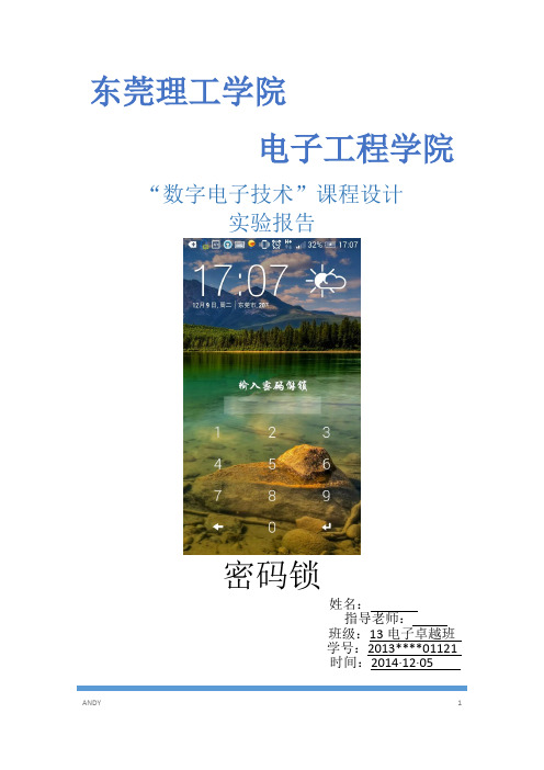
“数字电子技术”课程设计实验报告姓名:指导老师:班级:13电子卓越班 学号:2013*********时间:2014·12·05东莞理工学院电子工程学院密码锁目录一、选题意义 (3)二、方案论证选择 (4)2.1 设计要求 (4)2.2 拓展要求 (4)2.3 系统框图 (4)2.4 设计过程 (5)三、电路设计 (5)3.1 所需芯片及芯片管脚图 (5)3.2 CD4017构成的主题电路 (6)3.2确认键的电路设计 (6)3.3输入密码三次锁死系统原理分 (7)3.4用led显示当前输入密码个数 (8)3.5 综合电路 (8)四、电路调试及实物照片 (9)五、心得体会 (13)一.选题意义1概述电子密码锁是一种通过密码输入来控制电路或是芯片工作,从而控制机械开关的闭合,完成开锁、闭锁任务的电子产品。
它的种类很多,有简易的电路产品,也有基于芯片的性价比较高的产品。
应用较广的电子密码锁是以芯片为核心,通过编程来实现的。
2性能特点其性能和安全性已大大超过了机械锁,特点如下:1.保密性好,编码量多,远远大于弹子锁。
随机开锁成功率几乎为零。
2.密码可变。
用户可以经常更改密码,防止密码被盗,同时也可以避免因人员的更替而使锁的密级下降。
3.误码输入保护。
当输入密码多次错误时,报警系统自动启动。
4. 电子密码锁操作简单易行,一学即会。
5.干扰码功能在输入正确密码前可输入任意码。
6.安保功能如果连续输错4次密码将会自动断电3分钟。
7.紧急开启功能(Panic Open)出门时无需其他操作,只需一次的把手动作,可机械的开启门,所以遇到火灾等应急状况下也迅速,安全的开启门。
8.入侵感应功能在门上锁的状态下,有人破锁而入时,会发出强力的报警音。
9.火灾报警功能在室内如果温度达到75°左右,将会发出强力的报警音,同时锁会自动开启。
10.双重锁定功能外部强制锁定:在内部不能开启,适用于外出时,防止有人入侵。
8位二进制数字密码锁系统设计(赵俊峰)
8位二进制数字密码锁系统设计(赵俊峰)8位二进制数字密码锁系统设计外文文献翻译(译成中文3000字左右):1.Digital Circuit IntroductionDigital circuit definition:Completes with the digital signal to the digital quantity carries on the arithmetic operation and the logic operation electric circuit is called the digital circuit, or number system. Because it has the logic operation and the logical processing function, therefore calls then umeral logic circuit. Numeral logic circuit classification (according to function minute):1st, combinatory logic electric circuitThe abbreviation combination circuit, it becomes by the most basic logical gate electric circuit combination. The character is tic is: Output value only and then input value related, namely output only by then input value decision. The electric circuit has not remembered the function, the output condition changes along with the input condition change, is similar to the resistance electric circuit, like the accumulator, the decoder, the encoder, the data selector and so on all belong to this kind.2nd, succession logic circuitThe abbreviation sequence circuit, it is adds on the feed back logic return route by the most basic logical gate electric circuit (to output the electric circuit which input) or the component combination becomes, lies in the sequence circuit with the combination circuit essence difference to have the memory function. The sequence circuit characteristic is: The output not only was decided by then input value, moreover also the and circuit past condition concerned. It is similar to containing thestored energy part the inductance or the electric capacity electric circuit, like electric circuit and so on trigger, latch, counter, shift register, reservoir all is the sequence circuit typical component.Digital circuit characteristic:1st, simultaneously has the arithmetic operation and the logic operation functionThe digital circuit is take the binary system logic algebra as mathematics foundation, the use binary numeral signal, both can carryon the arithmetic operation and to be able conveniently to carry on the logic operation (with, or, non-, judgment, comparison, processing and so on), therefore extremely suits to application and so on operation, comparison, memory, transmission, control, decision-making.2nd, realization simple, the system is reliableBy binary system underlie numeral logic circuit, simple reliable, the accuracy is high.3rd, integration rate high, the function realization is easyIntegration rate high, volume small, the power loss is low is one of digital circuit prominent merits. Electric circuit design, service, maintenance nimble convenient, along with the integrated circuit technology high speed development, the numeral logic circuit integration rate is more and more high, integrated circuit block function along with small scale integration electric circuit (SSI),center scale integrated circuit (MSI), large scale integrated circuit(LSI), ultra large scale integrated circuit (VLSI)the development also from the part level, the component level, the part level, the board card level risesto the system level. The electric circuit design composition only must use some standards theintegrated circuit block unit connection to become. Also may use the programmable foreword logic array electric circuit regarding the non- standard special electric circuit, through programming method realization free logic function.Digital circuit application:Digital circuit and numeral electronic technology widespread application to science and technology each domain and so on television, radar, correspondence, electronic accounting machine, automatic control, astronautics.2.Digital code lock System Status and Development TrendRecent years, along with reform and open policy thorough development, electronic appliance's swift development. People's living standard had the very big enhancement. Each kind of upscale electrical appliances product and the valuables have for many families. However some unlawful elements are also more and more. This sees majority of person security consciousness also insufficient. Creates steals the phenomenon to be common. Therefore, more and more resident families worried to the property security problem. the alarm apparatus had been solving many problems by now for the people. But in the market alarm apparatus majority of use in some big company fiscal institution. The price is soaring, generally the people accept with difficulty. If redesigns and produces one kind moderately-priced, the performance keen reliable burglar alarm, will certainly plays a more effective role in security and the guarantee property security aspect. As the electronic code lock is a password to enter the control circuits, or chips, so as to control mechanical switches closed, the completion of the lock, closed the task of electronic products. It's a lot of species, there is a simple circuit products as well as chip-based products more cost-effective. Now a widerapplication of electronic locks is at the core chip.The electronic technology has obtained the rapid development, under its impetus, the electronic products nearly seeped society's each domain now, powerfully impelled in the social product development and the social becoming an information based society degree enhancement, simultaneously also is makes the modern electronic products performance further to enhance, the product renewal rhythm more and more is also quick. First the EDA technology after enters for the 21st century, obtained the very big development, its basic characteristic uses the higher order language description, has System the simulation and the synthesizing capacity. The VHDL hardware description language is designs the source document to be possible to use is similar with the C language written form, and uses the structural design method. Along with the people living standard enhancement, the password lock took the family security bodyguard's function is day by day important, it compared to has some unique superiority with the ordinary mechanical phase-lock, for example: Secret, the security performance is good, may not use the key, so long as remembers the password then unlock.The EDA technique develops trend: The EDA technique is after get into 21 centuries, because of more large-scale FPGA and continuously release of the cave m spare part are really imitate with design the both side support a standard hardware description, the function strong EDA software of the language continuously renews, increment, make the electronics EDA's technique get a larger development. The electronics technique is all-directions to bring into EDA realm, the EDA make electronics the boundary of each academics of realm be getting more misty, more with each other in order to forgive, the outstanding performance is at following few aspects: Makeelectronics design the result can definitely express to make possible with confirmation by independent intelligent property right; Design standard unit according to the ASIC of EDA tool have already covered large-scale electronics system and the IP pit mold piece; The soft hardware IP pit gets further confirmation in industry realm, technique realm and the design applied realm of electronics profession; The SoC efficiently low cost design technical maturity. Along with the semi-conductor technique, integrated technique and the calculator technical fast fierce development, design method and design means of electronics system all took place very big variety. Can say electronics EDA's technique's is an electronics design is a revolution of the realm. The design method of traditional” fix function integration piece ten on-lines" just and gradually with draws history stage, but is become modern main current of design of the electronics system according to the design method of chip. Be Gao Deng3 college's understanding and climbing to hold this advanced technique concerning the professional student and the large electronics engineer be certainly to be necessarily going, this not only is the demand of efficiency of the exaltation design, more that time generation need for develop, only climbed to hold the EDA technique just includes the competition that the ability participates the industrial market of the world electronics, then can exist with development. Along with the progress of science and technique revolution of the realm and electronics industryfield of the electronics design, also in the meantime to electricity course of teaching and research put forward more deeply higher request. Especially the EDA technique hasn't make widely available in the our country and control is this all new technique with universality, will to our country the electronics technical development have profound meaning.3.Electronic Lock System of Non-contact IC CardBased on the research of RS485 and TCP/IP Communication Protocol, the paper introduces an Electronic Lock System of Non-contact IC card and puts forwards the solution of the whole system. This system adopts distributed architecture and is combined with the centralized and unified management. It can be classified into three aspects: management center server, user building PC and Electronic Cipher Locks. The paper emphases on the general principle and the design of hardware and software of this kind of Electronic Cipher Lock system, which takes Micro-controller STC89C58RD+ chip as core and Philips ’ MFRC530 for RF base station. Comp ared with the traditional Electronic Lock system, this system has significant advantages. The results prove the feasibility of the scheme and show that the system is stable and has a good real-time performance.4. Electronic Cipher Locks by the Use of AT89C2051 MCUAs electronic products are developing towards intelligence and minimization, micro control unit(MCU) have become the first choice for controllers in the development of electronic products. In order to expand the applications of MCU in to household appliances, a new designing method of electronic cipher locks by the use of AT89C2051 MCU is introduced in this paper.It shows that thecipher lock is characterized by its low cost and high degreeof safety and practicality. Besides, it works well as a residence lock and has great potential for commercial development.5. Giving-alarm Electronic Password LockThis article introduces one kind of giving-alarm electronic password lock, using unidirectional thyristor as the storage cell. The digital key of this kind of lock is composed of 10 lightly touchedswitch. 5 of the codes open the lock, the other 5 codes are used to alarm. If the password is right, so long as pressing down the 5 digital keys at one time or according to the order, the electronic lock will be open quickly. If the password is wrong, pressing the giving-alarm key will bring a 30s alarm:“to catch the thief”.6. the Infrared Long-distance Remote Control Which the Numerical Ciphers LockSpecialized numerical ciphers lock the infrared long-distance remote control is one kind of quite advanced password switch, this article designs one through the telephone through the infrared remote control realization opposite party opening which locks with the equipment password, the user use handset dials in his/her family's fixed telephone, to the telephone number which dials carries on the recognition by the monolithic integrated circuit realization, with confirmed whether its number for does unlock the telephone number, if is master's telephone number, the monolithic integrated circuit sends out the signal control infrared launcher, the realization long-distance remote control unblanking.This article elaborated the infrared remote control basic principle and has designed the corresponding transmission and the accepting circuit, again uses correlation chip NE555, CX20106,HT9030 the function characteristic, the composition auxiliary circuit, forms the hardware diagram; Second step then key conducts the research to at89C51 monolithic integrated circuit, the cost design software designs and draws the flow chart. Finally this design essential duty is take AT89C51 as a core, various functions module organic union. Through the monolithic integrated circuit control, realizes the function which each separation component cannot complete. Namely finally realizes the infrared long-distance remote control which the numerical ciphers lock.1.数字电路简介数字电路定义:用数字信号完成对数字量进行算术运算和逻辑运算的电路称为数字电路,或数字系统。
数电课程设计密码锁
数
电课程设计 1.设计题目:
密码锁
2.设计要求:
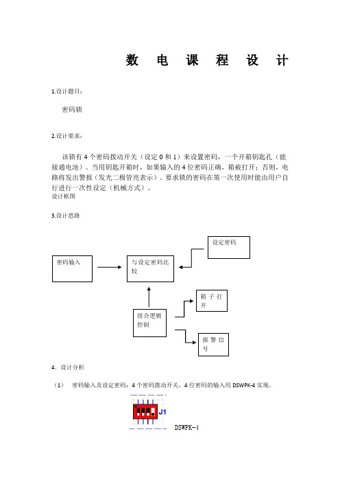
该锁有4个密码拨动开关(设定0和1)来设置密码,一个开箱钥匙孔(能接通电池)。
当用钥匙开箱时,如果输入的4位密码正确,箱被打开;否则,电路将发出警报(发光二极管亮表示)。
要求锁的密码在第一次使用时能由用户自行进行一次性设定(机械方式)。
设计框图
3.设计思路
4
.设计分析
(1) 密码输入及设定密码:4
个密码拨动开关,4位密码的输入用DSWPK-4实现。
DSWPK-4
(2)与设定密码比较
可用74x85 4位比较器,但由于未在multisim里找到,于是用4个74x86代替。
74x86
将两个74x138 3-8译码器级联成4-16译码器,如下图
其中6口接高电平
74x138真值表
5.电路原理图
Led1灯亮的时候是报警信号,led2灯亮的时候说明锁已打开,用开关A模拟钥匙,闭合时视为插入钥匙。
5v的VCC视为电池。
使用到的其他元件有,8输入与非门,3kΩ电阻,2输入或门,开关等。
- 1、下载文档前请自行甄别文档内容的完整性,平台不提供额外的编辑、内容补充、找答案等附加服务。
- 2、"仅部分预览"的文档,不可在线预览部分如存在完整性等问题,可反馈申请退款(可完整预览的文档不适用该条件!)。
- 3、如文档侵犯您的权益,请联系客服反馈,我们会尽快为您处理(人工客服工作时间:9:00-18:30)。
长沙学院
数电课程设计说明书
题目二进制密码锁的设计系(部) 电子与通信工程系
专业(班级) 通信工程
姓名XXX
学号XXXXXX
指导教师陈希
起止日期5月28号-6月1号
2010级通信工程专业课程设计任务书(课题九)
系(部):电子与通信工程系专业:通信工程
目录
摘要 (4)
1、二进制密码锁的设计电路的设计方案 (5)
1.1设计任务与要求 (5)
1.2设计思路与原理 (5)
1.3单元电路设计与参数计算 (7)
1.3.1输入密码﹑预设密码输入单元: (7)
1.3.2数字比较单元: (8)
1.3.3R﹑E﹑发光二极管显示单元: (8)
1.3.4使能端单元: (9)
1.3.5置0单元: (10)
2、Multisim仿真及PROTEL原理图的绘制 (10)
3、设计缺陷 (12)
4﹑总结与体会 (13)
参考文献: (14)
二进制密码锁的设计
摘要
数字密码锁是通过输入密码预设密码进行数值比较,如果密码一致,则锁被打开,否则不能打开。
本方案的以以上原理为基础,通过一些门电路的辅助,实现了实验要求的功能的功能。
关键字:数字密码锁
1、二进制密码锁的设计电路的设计方案
1.1设计任务与要求
(1)课题内容:
①.设计一个8位并行二进制密码锁,密码内容可通过开关进行设置。
②.设置8位输入按键,当不进行任何按键时,数码管显示“0”;当按键值与预置的密码完全符合时,数码管显示“R”,开锁状态LED灯亮;当按键值与预置密码不符合时,数码管显示“E”,开锁状态LED灯灭。
③.系统可设置一个使能输入端,当使能端为高电平时,密码锁能正常工作,反之,密码锁按键无效,数码管灭, 开锁状态LED灯灭。
(2)主要任务:完成该系统的硬件设计,调试好后并能通过仿真,最后就课程设计本身提交一篇课程设计说明书。
1.2设计思路与原理
通过每组八个的两组开关分别组成“输入密码”和“预设密码”,然后通过数值比较器,当比较相同时数码管输出字母R,当比较不同时数码管输出字母E,当不进行任何输入时数码管出0(由于一旦电路搭建完成,无论组成密码输入和密码预设的两组开关是处于闭合还是断开状态,都进行了输入,即:断开输入为高电平1,断开输入为低电平0,所以本实验通过外接电路模块来实现“当不进行任何输入数码管为0的功能”即:外接模块开关处于状态一时:无论输入密码和预设密码是什么,数码管均显示为0,当外接模块开关处于状态二时:数码管能进行正常的R,E转换)。
另外,设计中还设有一个使能端,使能端为高电平时数码管和发光二级管工作,使能端为低电平时,都熄灭。
另外,应当注意的是数码管的7个输入引脚要接电阻,如果不接电阻,当使能端从高电平拨至低电平,即:数码管从有显示到无显示时会闪烁,而不能完全熄灭。
图1.1 数字密码锁框图
图1.2 74HC85引脚图
图1.3 引脚端符号说明
图1.4 74HC85引脚极限值
图1.5 74HC85功能表
1.3单元电路设计与参数计算
1.3.1输入密码﹑预设密码输入单元:
单元说明:用两组开关组成八位二进制密码。
当开关处于断开状态时为逻辑电平1,当开关处于闭合状态时为逻辑电平0。
图1.6输入密码﹑预设密码输入单元电路图
表1.1输入密码及预设密码输入单元元件清单
元件序号型号主要参
数
数量备注
S1 ~S8 无无8 开关
S11
~S18
无无8 开关
1.3.2数字比较单元:
单元说明:一片74HC85芯片只能比较四位二进制数,这里用两片74HC85串联级联的方式组成八位二进制数值比较器。
低位片的3脚接高电平,2﹑4脚接低电平,即:JP1的3脚接高电平,2﹑4脚接低电平。
图1.7数字比较单元电路图
表1.2数字比较单元元件清单
元件序号型号主要参
数
数量备注
JP1~JP2 74HC85 5V 2 组成八
位二进制数值
比较器
1.3.3R﹑E﹑发光二极管显示单元:
单元说明:用一些逻辑与非门﹑非门﹑开关﹑电阻﹑与门﹑发光二极管组成。
图1.8 R﹑E﹑发光二极管显示单元电路
表1.3R﹑E﹑发光二极管显示单元元件清单
元件序号型号主要参数数量备注
U6﹑U7﹑U9 无无 3 二输入端与门
U1﹑U3﹑U4 无无 3 非门
U5 无无 1 异或门
F1—F7 无330欧7 电阻
U8 无无 1 而输入端与非门DS1 无无 1 七段显示器
D1 无无 1 发光二级管
1.3.4使能端单元:
单元说明:当使能端处在高电平时七段显示器和发光二极管工作,低电平时七段显示器和发光二极管不工作。
此模块应该特别注意七段显示器的7个输入端都要接330欧的电阻,防止使能端拨至低电平时七段显示器闪烁。
图1.9 使能端单元电路图
表1.4使能端单元元件清单
元件序号型号主要参数数量备注U9 无无 1 二输入端与门
U3 无无 1 非门F8﹑F10 无330欧 2 电阻
1.3.5置0单元:
单元说明:由于一旦电路搭建完成,无论组成密码输入和密码预设的两组开关是处于闭合还是断开状态,都进行了输入,即:断开输入为高电平1,断开输入为低电平0,所以本实验通过外接电路模块来实现“当不进行任何输入数码管为0的功能”即:外接模块开关处于状态一时:无论输入密码和预设密码是什么,数码管均显示为0,当外接模块开关处于状态二时:数码管能进行正常的R,E转换。
图1.10 置0单元电路图
表1.5 置0单元元件清单
元件序号型号主要参数数量备注
U2、U10 无无 2 开关
S22、S23、S24 无无 3 非门F9 无330欧 1 电阻
2、Multisim仿真及PROTEL原理图的绘制
图2.1Protel原理图
图2.2 Multism仿真图
表2.1总清单
元件序号型号主要参数数量备注S1 ~S8 S11
无无20 开关
~S18 S21~S24
JP1~JP2 74HC85 2 数值比较器U1~U4﹑U10 无无 5 非门U5 无无 1 异或门U6﹑U7﹑U9 无无 3 二输入端与
门U8 无无 1 二输入端与
非门F1~F10 无330欧10 电阻
DS1 无无 1 七段显示器D1 无无 1 发光二极管
3、设计缺陷
本次课程设计方案最大的缺陷莫过于任务要求的“当不进行任何输入时,数码管显示数字0”功能实现起来过于繁琐。
其次,Multism仿真电路图搭建的不过整洁也是这次我的课程设计不足之处。
4﹑总结与体会
这次课程设计可谓收获颇丰,通过本次课程设计学习到了很多书本上学习不到的东西,例如:出现问题后自我解决的能力,与同学之间的互相学习的能力。
这次课程设计虽然只用时一周,去让我们对以前理论课上学到的知识得到了很好的理解,是对理论知识的运用,深化理解。
而通过对文献资料的参照查找与对比,以及对仿真软件Multisim和Protel软件的学习。
不仅独立制作出了数字密码所电路的全过程设计、调试,而且初步学会了如何设计数字系统。
在查找文献资料中不仅能学到许多东西,而且学会了许多解决问题的方法;而对Multisim和Protel软件的学习,则更加提高自己实践操作能力的提高。
在设计过程中不断寻求解决方案与方法,独立进行学习与查找方案。
对课程设计说明书的撰写,进一步加强了各方面能的锻炼,分析能力进一步加强。
在书写课程设计时,不仅要进行单元块的调试,而且需要一步一步进行组装最后调试。
在进行逻辑分析时,还要对其进行不对思考改进,强化了独立解决问题的能力。
另外,Microsoft Office Word得到熟练应用。
当然,通过这次课程设计也让我看到了很多需要改进的地方。
完成个目标有很多种方法,而只有通过不断的改进我们的方案,不断地学习他人的长处,并化为自己的思想,才能尽可能的把我们的设计方案做得完美。
我的这个设计方案并不是最好,例如:在要求不进行任何输入时七段显示器显示数字“0”,我用的办法是外接电路模块控制。
虽然也能实现,但终觉得不完美。
英语方面的欠缺,也会使得设计受阻,在当今这个地球村的时代,我们不得不学号英语,已达到学习发达国家技术的目的。
就本次课程设计而言,就要用到两种英文软件,一种是Multisim软件,另一种是Protel软件。
这两个软件在本次设计中起到很关键的作用。
所以学好英语的重要性可见一斑。
参考文献:
[1] 康华光.电子技术基础数字部分第四版 [M] .北京:高等教育出版社,1998,1~386.
[2] 童诗白.模拟电子技术第二版[M] .北京:高等教育出版社,1988,1~100.。