DZS新-100系列中间继电器使用说明书ISO9001质量
欧尼臣 ESM-BT4.. 系列安全继电器 使用说明书
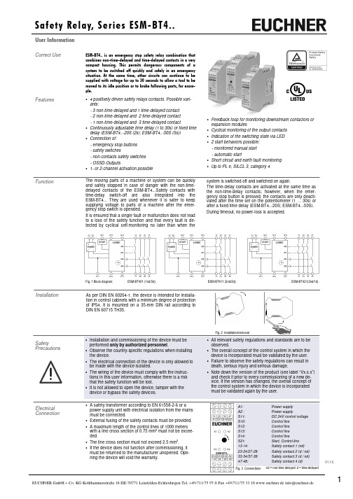
V1.1.0• Feedback loop for monitoring downstream contactors orexpansion modules• Cyclical monitoring of the output contacts • Indication of the switching state via LED • 2 start behaviors possible: - monitored manual start - automatic start• Short circuit and earth fault monitoring • Up to PL e, SILCL 3, category 4Correct UseESM-BT4.. is an emergency stop safety relay combination that combines non-time-delayed and time-delayed contacts in a very compact housing. This permits dangerous components of a system to be switched off quickly and safely in an emergency situation. At the same time, other circuits can continue to be supplied with voltage for up to 30 seconds to allow a tool to be moved to its idle position or to brake following parts, for exam-ple.Features• 4 positively driven safety relays contacts. Possible vari-ants:- 3 non-time-delayed and 1 time-delayed contact - 2 non-time-delayed and 2 time-delayed contact - 1 non-time-delayed and 3 time-delayed contact• Continuously adjustable time delay (1 to 30s) or fixed time delay (ESM-BT4..-20S (2s); ESM-BT4..-50S (5s)) • Connection of:- emergency stop buttons - safety switches- non-contacts safety switches - OSSD-Outputs• 1- or 2-channel activation possibleFunctionThe moving parts of a machine or system can be quickly and safely stopped in case of danger with the non-time-delayed contacts of the ESM-BT4...Safety contacts with time-delay switch-off are also integrated into the ESM-BT4... They are used whenever it is safer to keep supplying voltage to parts of a machine after the emer-gency stop switch is operated.It is ensured that a single fault or malfunction does not lead to a loss of the safety function and that every fault is de-tected by cyclical self-monitoring no later than when theInstallationAs per DIN EN 60204-1, the device is intended for installa-tion in control cabinets with a minimum degree of protection of IP54. It is mounted on a 35-mm DIN rail according to DIN EN 60715 TH35.system is switched off and switched on again. The time-delay contacts are activated at the same time asthe non-time-delay contacts; however, when the emer-gency stop button is pressed, the contacts are only deacti-vated after the time set on the potentiometer (1 … 30s) or after a fixed time delay (ESM-BT4..-20S; ESM-BT4..-50S).During timeout, no power-loss is accepted.Electrical ConnectionFig. 1 Block diagram: ESM-BT401 (1nd/3d); ESM-BT411 (2nd/2d); ESM-BT421(3nd/1d)V1.1.0Depending on the application or the result of the risk assessment according to EN ISO 13849-1, the device must be wired as shown in Fig. 1 to Fig. 11. Non-time delayed contacts can be used up to category 4, PL e, time-delayed safety contacts up to category 3, PL e.ApplicationsFig. 3:Single-channel emer-gency stop circuit with earth fault monitoring. (category 1, up to PL c)Fig. 2:Two-channel emergen-cy stop circuit with earth fault monitoring.(category 3, up to PL d)Fig. 1:Two-channel emergen-cy stop circuit with short circuit and earth fault monitoring.(category 4, up to PL e)Fig. 4:Two-channel sliding guard monitoring with short circuit and earth fault monitoring.(category 4, up to PL e)Emergency StopCircuitFig. 7:Automatic start (e.g. for application with a safety door).Max perm. delay during closing of the safety switches on S12 and S13: S12 before S13: 300ms; S13 before S12: anyWarning:Safety contacts switch when the power supply is connected.Fig. 8:Feedback loop for monitored manual start:The feedback loop monitors contactors or the expansion modules .Starting Behavior Feedback LoopNote: The items listed under “Electrical connection” must be observed during commissioning . Commissioning Procedure1. Wiring emergency stop circuit:Wirethe emergency stop circuit according to the requiredPerformance Level determined (see Fig. 1 to Fig 5). 2. Wiring start circuit:Wire the start circuit according to Fig. 6 or Fig. 7 to set the starting behavior. Warning:If “Automatic start” is set, bear in mind that the safety con-tacts will switch immediately after the power supply is connected.If“Monitored manual start” is set, the start button must be opened after wiring. 3. Wiring feedback loop:If your application provides for external contactors or ex-pansion modules, connect them to the device according to Fig. 8 or Fig. 9.4. Wiring power supply:Connect the power supply to terminals A1 and A2 (Fig. 10). Warning: Wiring only in de-energized state. 5. Set time delay:Set the desired time delay on the rotary knob (not for fixed delay time)Warning:Scale divisions should be regarding only as a setting aid. Always make shure to measure the delay time. 6. Starting the device:Switch on the operating voltage. Warning:If the “Automatic start” starting behavior is set, the safety contacts will close immediately.If the “Monitored manual start” starting behavior is set, close the start button to close the safety contacts. LEDs K1, K2, K3 and K4 are lit. 7. Triggering safety function:Open the emergency stop circuit by actuating the connec-ted safety switch. The safety contacts open immediately. Warning: Measure the delay-time. 8. Reactivation:Close the emergency stop circuit. If “Automatic start” is selected, the safety contacts will close immediately.If the “Monitored manual start” starting behavior is set, close the start button to close the safety contacts.Warning:In order to activate earth fault monitoring, the PE must be connected only to the power supply unit in accordance with EN60204-1.Corresponded to the application, the starting circuit have to be wired according to Fig. 6 or Fig. 7.Fig. 5:Two-channel emergency stop with pnp-outputs/OSSD-outputs with short circuit monitoring. (category 4, up to PL e)Fig. 9:Feedback loop for automatic start: The feedback loop monitors contac-tors or the expansion modules .Power supply andSafety contactsFig. 10:Power supply A1 and A2.(Power supply according to techn. data )Fig. 11:Connecting load to safety contacts.(Figure shows example.Voltage …+V“ according to techn. data)Fig. 6:Manual start.User InformationV1.1.0MaintenanceDevice cannot be switched on again after an emergency stop:• Check whether the emergency stop circuit was closed again.• Was the start button opened before closing of the emer-gency stop circuit (with manual start)? • Is the feedback loop closed?If the fault still exists, perform the steps listed under “Commissioning Procedure”.If these steps do not remedy the fault either, return the device to the manufacturer for examination.Opening the device is impermissible and will void the warranty.What to Do in Case of a Fault?The device must be checked once per month for proper function and for signs of tampering and bypassing of the safety function (to do this, check the wiring of the device and activate the emergency stop function. Check the delay time).The device is otherwise maintenance free, provided that it was installed properly.Note:Additional data can be requested from the manufacturer for applications that deviate from these conditions.SafetyCharacteristics According to EN ISO 13849-1The device is certified according to EN ISO 13849-1 up to a Performance Level of PL e.Device does not switch on:• Check the wiring by comparing it to the wiring diagrams. • Check the safety switch used for correct function and adjustment.• Check whether the emergency stop circuit is closed. • Check whether the start button (with manual start) is closed.• Check the operating voltage at A1 and A2. • Is the feedback loop closed?*) If several ESM-BT4.. devices are closely spaced under load, the max. total current at the ambient temperature of T=20 °C: 9 A; at T=30 °C: 3 A; at T=40 °C =1 A. If these currents are exceeded, a spacing of 5 mm between the devices must be observed.Safety characteristics according to EN ISO 13849-1 for all variants of ESM-BT4 Load (DC-13; 24 V) <= 0.1 A <= 1 A <= 2 A T10d [years] 20 20 20 Category: Time-delay Non-time-delay 3 4 3 4 3 4 PLe e e PFHd [1/h]: Time-delay Non-time-delay8,84E-08 4,22E-088,84E-08 4,22E-088,84E-08 4,22E-08 nop [cycle / year]<= 500,000<= 350,000<= 100,000User InformationV1.1.0Dimension DrawingS u b j e c t t o t e c h n i c a l m o d i f i c a t i o n s , n o r e s p o n s i b i l i t y i s a c c e p t e d f o r t h e a c c u r a c y o f t h i s i n f o r m a t i o n . © E U C H N E R G m b H + C o . K G 109074-09-02/18 (T r a n s l a t i o n o f t h e O r i g i n a l O p e r a t i n g I n s t r u c t i o n s ) Fixed TerminalsPlug-InTerminals。
欣灵 DZB、 DZS-10B系列中间继电器 说明书

一、概述本继电器用于直流操作的各种保护和自动控制线路中作为辅助继电器,以增加接点的数量及接点的容量。
DZB-11B、DZB-12B、DZB-13B型继电器为电压起动电流保持的中间继电器;DZB-14B型继电器为电流起动电压保持的中间继电器;DZB-15B型继电器为电流或电压动作,电流保持或电压保持的中间继电器。
DZS-11B、DZS-13B型继电器为动作延时继电器;DZS-12B、DZS-14B型继电器为返回延时继电器;DZS-15B、DZS-16B型继电器为电压延时动作和电流保持的继电器。
二、主要技术数据1.DZB-10B系列中间继电器技术数据见表1;热点断开容量:在电压不大于220伏,电流不大于1安的直流感性负荷电路(时间常数为5×10⁻³秒)中为50瓦;在交流电路中为250伏安。
2.DZS-10B系列延时中间继电器额定值见表2;1)动作电压不大于70%额定电压,返回电压不小于2%额定电压(返回延时继电器此项不要求)。
2)动作延时在额定电压下不小于0.06秒。
3)返回延时:在通电时间不小于0.5秒然后断开电源,其返回时间不小于0.4秒。
4)功率消耗:在额定电压下不大于5瓦。
5)接点容量:在电压不大于220伏,电流不大于1安的直流感性负荷电路(时间常数为5×10⁻³秒)中,断开容量为50瓦;在交流回路中为250伏安。
接点长允许通过电流不大于5安。
型 号额定值线圈电阻(Ω)保持线圈数量(匝)接点形式及数量动作值不大于保持值不大于返回值不小于动作时间不大于(s)功率消耗不大于(W) 电压(V)电流(A)电流 电压 常开 转换 电流 电压 电流 电压电流线圈电压线圈DZB-11B 2201104824 0.512488900±80033 3Ie70%Ue80%Ie70%Ue2% 0.054475.52150±200DZB-12B 445±406 135±10DZB-13B 220 0.5124811400±10001 3 3 110 2750±20048 570±5024 150±10DZB-14B 220 0.5124816600±10001 3 3 4 4 110 5230±50048 900±6024 225±30DZB-15B 220 0.250.512488900±8001 1 3 3 4 7 110 2150±20048 445±9024 130±10三、正常使用条件(1)海拔高度不超过2000米;(2)周围最大变化范围为-25℃到+40℃;(3)最湿度的月平均最大相对湿度为90%,同时该月的月平均最低温度为25℃;(4)与垂直面的安装倾斜度不超过5°;(5)无显著摇动和冲击振的地方;ISO9001质量体系认证企业(6)在无爆炸危险的介质中,且无腐蚀金属和破坏绝缘的气体与尘埃; (7)在没有雨雪侵袭的地方。
DZ-200说明书

DZ-200系列中间继电器用途本系列中间继电器用于各种保护和自动控制装置中,以增加保护和控制回路的触点数量和触点容量。
技术数据1、动作值、保持值动作电压与保持电压不大于70%额定电压,动作电流与保持电流不大于80%额定电流。
2、返回值:不小于5%额定值,DZB-200及DZS-200不小于3%额定值。
4、热稳定性(环境温度40℃时);1)电压绕组长期耐受110%额定电压温升不超过60℃。
2)电流绕组能耐受三倍额定电流,历时5S。
6、绝缘电阻继电器电路与外壳导磁体间,在电气上无联系的各电路之间的绝缘电阻在温度+40℃相对湿度不大于85%的条件下,48小时后不低于10MΩ。
7、绝缘强度继电器电路与外壳,在电气上无联系的各电路之间能耐受交流50Hz,电压2000V,历时1min。
继电器线圈的绕组间能耐受交流50Hz 电压500V历时1min。
电寿命后仍能满足2~4条的要求。
机械寿命后经过调整仍能满足2~4条的要求。
SERIES DZ-200 AUXILIARY RELAYS APPLICATIONSeries DZ-200 Auxiliary Relays are used in various protective and automatic control devices to increas the contact number and the contact capacity of the protective and conrtol circuits.TECHNICAL DATA1. Operating value and holding value:The operating voltage and the holding voltage are not higher than 70% of the rated voltage.The operating current and the holding current are not greater than 80% of the rated current.2. Resetting value:≮5% of the rated value;For type DZB-200 and DZS-200 relay: ≮3% of the rated value.3. Power consumption:4. Thermal stability(at ambient temperature of 40℃)1)The temperature rise does not exceed 60 ℃ when the voltage winding is applid with a voltage of 110% of the rated voltage continuously.2)The current winding can withstand three times the rated current for 5 sec.5. Contact rating6. Insulation resistance:The insulation resistance between the relay circuits and the case, and between circuits without electrical connections are not less than 10MΩ after the relay has been placed in a test chanber at a temperature of +40℃ and relative humidity of 85% for 48 hours.7. Strength of insulation:The strength of insulation between the relay circuit and the case and between circuits without electrical connection can withstand a test voltage of a.c.2000v,50Hz, for 1 min., and that between the windings of the relay coil can withstand a test voltage of a.c.500V,50Hz,for 1 min.8. life:After tested for electrical life, the relay can still satisfy the requirements specified in terms 2-4.After tested for mechanical life and readjusted, the relay can still satisfy the requirements。
XJ-100使用说明书
XJ-100小电流接地故障选线及监测系统用户手册淄博科汇电气有限公司Kehui Electric Co. Ltd.,Zibo目录1XJ-100小电流接地故障选线及监测系统简介 (5)1.1 原理与概述 (5)1.2总体结构 (6)1.3 主要技术指标及技术特点 (7)2XJ-100小电流接地故障检测装置 (9)2.1 装置概述 (9)2.2 装置的结构 (9)2.3 装置的前面板说明 (10)2.4 装置组屏 (10)2.5 装置接线 (11)2.5.1装置的后面板接线端子图 (11)2.5.2装置的接线说明 (11)2.6 装置使用指南 (12)2.6.1开机 (12)2.6.2复位 (12)2.6.3设置与PC机通讯波特率、内部时钟的时间、数码管显示亮度 (12)2.6.4与T-GPS时钟通讯的波特率设置 (13)2.6.5故障启动、记录 (13)2.7 装置的运行维护及异常处理 (14)2.7.1定期检查装置 (14)2.7.2通风及散热 (14)2.7.3常见异常情况及处理 (14)3XJ-100小电流接地故障分析系统的安装 (16)3.1 XJ-100软件运行的硬件环境 (16)3.2 XJ-100软件运行的软件环境 (16)3.3 XJ-100软件的安装步骤 (16)3.4 XJ-100软件系统的外部连接 (16)3.5 XJ-100软件系统的启动 (17)3.6 XJ-100软件系统的卸载 (17)4XJ-100小电流接地故障分析系统的使用 (18)4.1 运行方式选择 (18)4.2分站运行方式下的配置 (18)4.3调度端运行方式下的配置 (21)4.4 XJ-100软件的主窗口 (21)4.4.1主窗口布局 (21)4.4.2主窗口操作 (22)4.5 XJ-100软件的主菜单 (23)4.5.1系统设置菜单 (23)4.5.2通讯菜单 (24)4.5.3数据维护菜单 (26)4.5.4查看菜单 (27)4.5.5帮助菜单 (27)4.6 波形分析 (28)4.7 故障统计 (28)本手册为您提供了科汇电气有限公司生产的XJ-100小电流接地故障选线及监测系统的各项功能和操作方法的介绍。
DZ-10系列 中间继电器 说明书

C
继电器类
C-1921 适用范围DZ-10系列
中间继电器 2.1 继电器的规格(见表1)
2.2 动作值:为30-70%额定电压值。
2.3 返回值:不小于额定值的5%。
2.4 动作时间:当输入激励量为额定值时,继电器的动作时间不大于45ms。
2.5 返回时间:当输入激励量由额定值降至零时,继电器的返回时间不大于60ms。
2.6 功率消耗:当输入激励量为额定值时,继电器的功率消耗不大于7W。
2.7 热稳定值:当环境温度为+40℃,继电器绕组能长期承受110%额定值,其线圈温升不超过65℃。
2.8 触点容量 (见表2)
2 主要参数及技术性能
DZ-10系列中间继电器(以下简称继电器)作为辅助继电器,用于各种保护线路中,以增加主保护继
电器的触点数量或触点容量。
DZ-15型中间继电器具有两付动合和两付动断触点。
DZ-16型中间继电器具有三付动合和一付动断触点。
DZ-17型中间继电器具有四付动合触点。
有感-3
T=5×10S 5
DC100W AC1000VA
表 2
220,110220,110表 1
直流:12、24、48、110、220V 用于直流电路DZ-16DZ-17341---
3 外形及安装尺寸
4 订货须知
订货时须指明型号、额定电压及接线方式(板前或板后)。
DZ-200系列 中间继电器 说明书

触点形式 002
006
202
220
240
400
402
420
600
602
620
800
004
060
062
080
242
260
422
440
024
204 002 006 202 220 240 400 402 420 600 602 620
绕组类型
一个电压 工作绕组
一个电流 工作绕组
C-197
额定电压(V)
额定电流(A)
2 型号及含义
D ZY-2 □□
D ZL-2 □□ D ZJ-2 □□
触点编号 01 02 03 004 05 06 07 08 09 10 11 12 13 14 15 16 17 18 19 20 21 22 触点型式 002 006 202 220 240 400 402 420 600 602 620 800 004 060 062 080 242 260 422 440 024 204 设计序号 直流电压操作电磁式中间继电器
DC 220 110 48 24 12
AC 380 220 127 110 100 60 36 12
0.25 0.5 1 2 4 8
继电器类
型号 DZL-212、DZL-212X DZL-213、DZL-213X DZL-214、DZL-214X DZL-215、DZL-215X DZL-216、DZL-216X DZL-217、DZL-217X DZL-218、DZL-218X DZL-219、DZL-219X DZL-220、DZL-220X DZL-221、DZL-221X DZL-222、DZL-222X DZB-213、DZB-213X DZB-214、DZB-214X DZB-217、DZB-217X DZB-226、DZB-226X DZB-228、DZB-228X DZB-233、DZB-233X DZB-243、DZB-243X DZB-257、DZB-257X DZB-259、DZB-259X
dzs100系列中间继电器

DZS-100系列中间继电器1 用途DZS-100系列中间继电器(以下简称继电器),作为辅助继电器,用于直流操作的保护回路中,以增加主保护继电器的接点数量或接点容量。
DZS-115,DZS-117型为延时动作继电器;DZS-127,DZS-136型为延时电压动作和电流保持继电器;DZS-145型为延时返回继电器。
2 结构概述DZS-100系列继电器为吸片式电磁继电器,继电器的线圈装在山形导磁体的圆柱铁心上,DZS-115、117型只有一个工作绕组(电压绕组);DZS-127、136型有一个工作绕组(电压绕组),和二个保持绕组(电流绕组)。
在线圈上面或下面的圆柱形铁心上同时装有阻尼圈,由此获得了继电器的延时动作或延时返回。
继电器的动、静接触系统分别固定于导磁体的衔铁和磁轭上,衔铁与磁轭用支柱铰链,借拉力弹簧的作用,使继电器返回和处于打开位置。
继电器安装在垂直屏板上,可以前面接线,也可以后面接线,其内部接线示于图1。
3 技术数据3.1 继电器按照额定数据和接点形式的分类列于表1。
3.2 动作电压: 不大于70%额定电压。
3.3 动作时间:不小于0.06秒(DZS-145型除外)。
3.4 保持电流:不大小80%额定电流(仅指DZS-127、136型)。
3.5 返回时间:(1)D ZS-145型,在额定电压下,通电时间不小于O.5秒, 然后切断电源, 继电器的返回时间不小于O.4秒, 在额定电压下切断电源, 同时将绕组端子短接,继电器的返回时间不小于0.8秒;(2)其他各型号继电器,切断电源后立即返回。
3.6 绕组温升:当环境温度为+40℃时:(1)电压绕组长期耐受110%额定电压,不超过60℃;(2)电流绕组允许通过3倍额定电流,历时5秒。
3.7 功率消耗:在额定值下,(1)DZS-115、117型,不大于3.3瓦;(2)DZS-127、136型,电压绕组不大于5.5瓦;电流绕组不大于2.5瓦;(3)DZS-145型,不大于6.5瓦。
初学电工必知必看-中间继电器和时间继电器
初学电工必知必看:中间继电器和时间继电器在传统电气工控线路当中,各种规格种类的接触器是当仁不让的主角,有道是红花还需绿叶衬,各种功能的继电器便成为线路的当中的配角,虽不起眼但流光溢彩,各领风骚数。
我们在工控线路里最常见到的当属中间继电器和时间继电器了。
起学校间继电器主要为解决沟通接触器帮助触点不多而产生的。
其在线路KA。
它的工作原理和沟通接触器一样,都属于电磁吸合工作方式。
常见的中间继电器型号有JZ7系列和JZC4系列,它们都有4对常开触点和4对常闭触点,JZC4系列中间继电器还可多加装一组外挂触点。
它们在线路里的功能是完成启停、联动、互锁等动作。
它们的长度容量一般为5A左右,由于没有消弧罩故无法拖动较大负载,使用过程中切勿当做接触器使用。
它们的线圈电压分为AC36V、127V、220V、380V4四大等级。
由于它体积小,触点众多,接线便利的优点在负载的电控线路当中出镜率极高。
凡是用到延时功能的电路当中,必少不了时间继电器。
时间继电器在线路中的为KT,它分为通电延时型和断电延时型两大类,一般常见的为通电延时型继电器。
过去多使用空气阻尼式时间继电器,它的好处是即可当通电延时型也可用作断电延时型时间继电器使用,转换方法为颠倒其吸合衔铁的位置即可,而且它还供应一对瞬动触点,但是它体积大,延时范围小,时间精度低等缺点,现在已基本被电子式ST3等型号的时间继电器所取代。
电子或智能式时间继电器计时精确,时间设置范围广,体积小,但它们多为通电延时型时间继电器,若要完成断电延时功能还需附加额外线路或选择专用型的时间继电器,此外该型继电器还极少有携带瞬动触点的型号消失。
时间继电器最经典的应用非星三角自动转换线路莫属。
除了上述两种常见的继电器外,还有速度继电器。
它在线路中的为n。
它一般套装在电动机主轴上使用,当电动机转速上升到肯定范围时,它的触点便动作,而当电动机速度回路到动作转速以下时,其触点复位。
速度继电器常用与反接制动或能耗制动等制动类线路当中,现在已不多见。
- 1、下载文档前请自行甄别文档内容的完整性,平台不提供额外的编辑、内容补充、找答案等附加服务。
- 2、"仅部分预览"的文档,不可在线预览部分如存在完整性等问题,可反馈申请退款(可完整预览的文档不适用该条件!)。
- 3、如文档侵犯您的权益,请联系客服反馈,我们会尽快为您处理(人工客服工作时间:9:00-18:30)。
一、用途 本继电器作为输助继电器,用于直流操作的保护回路中,以增加主保护继电器的接点数量或接点容量。
二、原理简介
该继电器为吸合式电磁继电器。
继电器的线圈装在山字形导磁体的圆柱铁芯上,靠近衔铁工作气隙处装有阻尼圈。
当线圈通电时,铜环中感应出的电流所产生的二次磁通阻碍着衔铁与铁芯之间气隙中主磁通的增加,因此具有动作延时。
DZS-145型继电器铜环装在铁芯根部,此外,尚绕有短路线圈和弱弹力长形弹簧,使继电器具有返回延时功能。
DZS-115、DZS-117型为延时动作继电器;DZS-127、DZS-136型为延时电压动作和电流保持继电器;DZS-145型为延时返回继电器。
本继电器为吸片式电磁继电器。
DZS-115、DZS-117型有一个工作线圈(电压线圈);DZS-127、DZS-136型有一个工作线圈(电压线圈)和两个保持线圈(电流线圈);DZS-145型有一个工作线圈(电压线圈)和一个阻尼线圈。
在线圈上面或下面的圆柱形铁芯上同时装有阻尼圈,由此获得了继电器的延时动作或延时返回。
三、主要技术数据
DZS-100系列中间继电器技术数据
型号 额定值 动作电压不大于 动作时间不小于(S) 保持电流不大于 返回时
间不小
于(S) 功率消耗不大于(W) 接点数量 电压Ue (V) 电流Ie (A) 常开 常闭
DZS-115 220 110 70%Ue 0.06 — 立 即 返 回 3.3 2 2 DZS-117 48,24 4 — DZS-127 220,110 1,2,4 80%Ie 5.5(电压线圈) 4 — 48,24 2,4,6 DZS-136 220,110 1,2,4 2.5(电流线圈) 3 — 48,24 2,4,6
DZS-145 220,110 48,24
* 6.5 2 2 *在额定电压下,通电时间不小于0.5秒,切断电源后返回时间不小于0.4秒;如切断电源,同时将线圈端子短接,返回时间不小于0.8秒。
当环境温度为+40℃时,电压线圈长期耐受110%额定电压,温升不超过60℃;电流线圈允许通过3倍;额定电流,历时5秒。
DZS-100系列中间继电器接点容量
负 荷 电压(V) 最大继开电流(A) 长期电流(A) 直流 交流
无 电 感 220 110 — — 1 5
5 有 电 感 (T=5×10⁻³S) 220 110 — — 0. 4 1. 4
*交 流 — — 220 110 5 10
*此项仅供参考
四、正常使用条件
(1)海拔高度不超过2000米;
(2)周围最大变化范围为-25℃到+40℃;
DZS-100系列中间继电器使用说明书
ISO9001质量体系认证企业
(3)最湿度的月平均最大相对湿度为90%,同时该月的月平均最低温度为25℃;
(4)与垂直面的安装倾斜度不超过5°;
(5)无显著摇动和冲击振的地方;
(6)在无爆炸危险的介质中,且无腐蚀金属和破坏绝缘的气体与尘埃;
(7)在没有雨雪侵袭的地方。
五、内部接线图
六、外形及安装尺寸
七、订货须知
(1)继电器的名称和型号;
(2)额定电流、电压;
(3)安装结构;
(4)订货数量。