12LBSA-54立式斜流泵
苏州尔泵有限公司产品说明:GSG 漏斗式浇筑式油泥泵 API 610 类别 BB5说明书
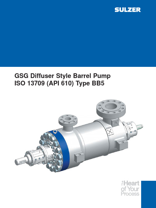
GSG Diffuser Style Barrel Pump ISO 13709 (API 610) Type BB5Extensive Product RangeSulzer Pumps has a long history of providing innovative pumping solutions to business partners in the following industries:Oil & GasHydrocarbon Processing Pulp and Paper Power Generation Food, Metals & Fertilizers Water and WastewaterHydrocarbon ProcessingHydrocarbon extraction plants,refineries, petrochemical plants and gas plants operate sophisticated production processes requiring reliable pumping solutions.Continuous product innovations such as our improved line of hermetically sealed, horizontal and vertical process pumps, are helping the industry improve its operational efficiency.Sulzer Pumps, with its high-quality product line, is known for being able to consistently meet these expectations.All our pumps are engineered in line with the latest standards issued by API, ISO and ANSI in order to ensure reliable and safe operation at your site. The Hydrocarbon Processing Industry is one of the core business segments within Sulzer Pumps.Following industry practice, we further subdivide the segment into:Synfuels Refining Gas Processing Petrochemicals Nitrogenous FertilizerThe market - and therefore our customers - requires specialty applications for each subsegment.Application RangeThousands of GSG pumps are installed around the world. They are found in:Power Plants RefineriesPetrochemical Plants Gas Processing Plants Onshore and offshore water injection servicesOnshore and offshore crude shipping serviceOnshore crude oil, refined product and LPG pipeline servicesHigh pressure and high or low temperatures are GSG services.DesignThe GSG is built to the latest edition of ISO 13709 (API 610). It is a type BB5,horizontal, radially split, diffuser type,multistage barrel pump. The rotor stack can be either inline (all the impellers facing towards the driver) or back-to-back. On the smaller pumps,the inboard seal chamber and bearing housing must be removed for cartridge removal. On larger pumps,the entire cartridge can be removed as an assembly to speed overhaul or re-rate turnaround time.The barrel is available as either a casting or forging with a variety of flange ratings to meet individual specifications. It is normally centerline supported for thermal stability and maximum nozzle load capacity. The barrel closure is either the traditional flanged head-studs and nuts, flanged head-Supernuts™, or Sulzer’s patented Twistlock closure for speedy removal and assembly.The inner cartridge consists of stacked diffuser/impeller sets. A double suction first stage impeller is available on all but the smallest sizes.Axial thrust is compensated by a balance drum for inline stacked rotors.The diffusers hydraulically balance radial forces. For those services where intermediate pressure takeoff is needed, higher flow diffuser/impeller sets can be utilized up to the takeoff stage, and then lower flow sets are used after the takeoff stage to optimize efficiency and performance.When design conditions change, re-rates are similarly achieved using different diffuser/impeller combin-ations, or blank stages—all in the same barrel.For applications on light gravity fluids with many stages, a back-to-back rotor stack is utilized to allow direct drive at normal motor speeds and provide improved rotordynamics. In such rotors, the opposed impellers cancel most of the axial thrust. The center bushing and throttle bushings take most of the residual axial thrust,so the thrust bearing loads are minimal. The back-to-back design allows the use of a 7300 series ball thrust bearing—and saves the substantial cost and maintenance components associated with lube oil systems. For high pressure and high energy levels, inline, or back-to-back stack, high speed, semi-stiff rotor designs are available.Depending upon pump size, power,and rotor design, the pumps can be supplied with ring oil or oil mist lubricated antifriction bearings, ring oil lubricated sleeve radial—ball thrust bearings, or pressure lubricated sleeve radial—tilting pad thrust bearings.MaterialsAll common ISO 13709 (API 610)material combinations are available.GSG Inline Design Features and BenefitsCasing CoverFlanged head, studs/nuts Flanged head, Supernuts™O-ring or spiral wound gasketMechanical SealsThrust Bearingbrass cages, orforce INPRO™with 360°Wear parts offered are the result of a year of wear testing by Sulzer Variety of materials, hardness, and hard coatings available depending on pump material and application PEEK with reduced clearances available on clean fluids for enhanced efficiencyfitsFor HPI applications shrink fit, axially secured impellers, and stepped shaft at each stageBlank stages can be supplied for future conditionsInterstage TakeoffPartial flow takeoff from intermediate stageAble to stack high capacity and low capacitydiffusers/impellers on same rotor for optimized stagetakeoffCommon on boiler feed pumps Available on recycle process applications Saves cost of additional pumpFirst Stage ImpellerLow Nss design is standardDouble suction available on all butsmallest sizesImproved NPSHr designs availableRadial BearingsInpro™bearing isolatorCarbon steel bearing housing with360°supportRing oil or oil mist lubricated rolleror ball bearing with C-3 clearanceRing oil or force feed lubricatedsleeve bearingsavailableRobust Shaft and RotorDesigned for low stress levelFully machinedDynamically balancedStraight bore, tapered bore, orhydraulic fit under couplingavailable per ISO 13709 (API610)BarrelCenterline mounted for thermal stabilityand maximum nozzle load capabilityCast with nozzles and flangesForged barrel with NDE of nozzle weldsWarm-up flow through discharge drain notrequired below 260°C (500°F). Warm-upflow required for higher temperaturesPin-and-key-slot thermal expansionsystemJacketing, insulation or noise blanketsavailablePump Inner Cartridge AssemblyStage casings sealed by dischargepressureFree to expand towards discharge coverduring warm-upInner tie bolts for assembly/disassemblyCoupling hub, inboard radial bearing and inboard seal chamber removal required on small pumps to remove cartridgeLarger pumps have barrel bore diameters larger than bearing housing which allows cartridge to be removed with those partsassembledCenter and throttle bushing absorb residualthrust and only breakdown half of dischargeAxial thrust stable even with worn clearances BearingsInpro™360°First Stage ImpellerLow Nss design is standardDouble suction available on all but smallest sizes Improved NPSHr designs availableBarrelCenterline mounted on hot servicesGSG InlineFulfills the majority of requirements for BB5 pumps with either cast or forged barrels to meet customerspecifications.Multivane diffusers balance radial loads. Balancingdrum takes the majority of axial thrust load. Heavyduty bearings support the rotor and carry residualthrust loads.Smaller size pumps fitted with ring oil lubricated antifriction bearings. Oil mist lubrication optionalAll but smallest sizes may be fitted with pressure lubricated sleeve radial, double acting tilting pad thrust bearings, lube oil systems, bearing RTD’s, X-Y vibration probes and Keyphasor, etc.Maximum number of interchangeable stage pieces minimizes spares parts inventoryIn direct drive applications, clearly the best selection up to stage limits. If still more head is needed, first consider GSG back-to-back and direct drive. If that does not meet head requirement, then consider GSG inline with higher Speed—using gear box or VFD.For very high head and high energy levels beyond GSG back-to-back direct drive capabilities, GSG with semi-stiff rotor design (like Sulzer’s HPcp, HPT pumps) can be offered. Could justify stand-alone, single unit—no standby. Discussion recommended.GSG: Inline and Back-to-Back Design Features and BenefitsGSG Back-to-BackWith up to 16 stages available, fulfills direct driveapplications that require more head than is availablefrom direct drive inline GSGMultivane diffusers balance radial loads. Opposedimpellers balance majority of axial thrust. Centerbushing and throttle bushing take nearly all the residualaxial thrust. Even when clearances are worn, axialand radial loads remain balanced.Fan cooled, ring oil lubricated, sleeve / ball thrust bearing without lube systems are common up to ISO 13709 (API 610) Table 9 limits, or Sulzer limits depending upon application. Significantly reduces installed cost and provides simple, reliable pumps.When even high speed GSG with semi-stiff inline rotor does not meet head requirements, or cannot meet rotordynamic requirements a GSG with semi-stiff back-to-back rotor can be offered.To speed the repair of a GSG pump,larger sizes are designed using that cartridge concept. The pump coupling hub, inboard bearing housing, seal chamber and hydraulic cartridge slide through the barrel for quick removal.Re-installation is just as fast. For evenfaster turnaround, the Sulzer patented Twistlock design puts an end to hours of torquing the barrel cover nuts. For remote locations or offshore this can be especially time and cost saving.Small GSG pump barrel bore are so small that the coupling hub, sealchamber and bearing housing will not fit through. Those parts have to be removed on those pumps before the cartridge is pulled.Rapid pump dismantlingThe innovative Sulzer Twistlock barrel cover design provides effective sealing and eliminates the usual requirements of torquing many fasteners to very high values—taking hours. The Twistlock also reduces the end cover flange area required thus reducing weight—an added bonus for offshore installations.Sulzer’s patented TwistlockThe assembled cartridge can be removed as one piece on larger pumps.Installation sequence:Cover in placeCover introduced and partially rotatedCover locked and securedOther Sulzer Barrel Pump ModelsWhen preferred or for erosive, sandy services, Sulzer’s CP opposed impeller, dual volute barrel pumps are proven performers. Heads to 6,700 m (22,000 ft)Sulzer’s HPcp (inline or back-to-back) is the global leader in large water injection services from 5 MW to 30 MW.Heads to 6,500 m (21,000 ft)Sulzer’s HPT boiler feed pumps are renowned for their reliability. Sizes to over 40 MW (55,000 hp) cover the majority of power plant needs.Performance RangeOperating DataQ (m 3/h)Q (USgpm)Bearing optionsFan cooled ring oil, or oil mist lubricated antifrictionbearings, orRing oil lubricated sleeve radial bearings withantifriction thrust bearing, orForce feed lubricated sleeve radial bearing and double acting tilting pad thrust bearingA variety of bearing instrumentation is available tomeet specificationsRotor and Impeller optionsFor ISO 13709 (API 610) applications, impellers areindividually axially secured and are shrink fit to theshaft—which is stepped under each impeller for ease of assemblyFor other applications a slip-fit impeller stack isavailableStraight bore, tapered bore, or hydraulic fit couplinghub is available per ISO 13709 (API 610)GSG “inline” or “back-to-back” rotor design.Double Suction first stage impeller for lower NPSHr.High temperatures and options for bottoms / residuesProven coke crusher available for services with coke particlesPump warm-up not required below 260°C (500°F).Warm-up flow required for higher temperaturesPin-and-block thermal expansion system provided on hot servicesJacketing, insulation or noise blankets availableGSG OptionsCheck our worldwide offices at*******************************E 00612 10.2004 Copyright ©Sulzer PumpsThis brochure is a general presentation. It does not provide any warranty or guarantee of any kind. Please, contact us for description of the warranties and guarantees offered with our products. Directions for use and safety will be given separately. All information herein is subject to change without notice.。
蝶式水泵控制阀的水锤防护功能及卡洛湖泵站的水力坡度计算
转 / 分 钟 ( 水 泵 转 速 为 90% 时 , Q=2 880m3/h , H=109.35m,N=1 458Kw,转速=2 655 转/min)。 运行要求:两台水泵变频调速运行,一台备用泵软 启动工频运行。变频调速水泵配套变频电机。单台 取水泵后设置 DN900、PN25 的蝶式水泵控制阀和 检修蝶阀各一台;
图 4 蝶式水泵控制阀流场迹线图
4 主要技术参数(表 1)
表 1 主要技术参数
公称尺寸(mm) 公称压力(MMPa) 使用温度(℃)
300~2000
1.0~6.3
0-80
适用介质 清水、原水
开阀时间(s) 3~60 可调
快关时间(s) 缓闭时间(s)
≤3
6~120 可调
5 卡洛湖泵站水力坡度计算
5.1 项目简介
该工程自常水位标高为 160m 的卡洛湖,通过 一条 DN1200 的输水管网输送至海拔为 161m 的生 产高位水池内贮存后,再通过重力流输送到厂区、 生活区。设计取水规模约为 120 000m3/d,共设置 三台取水泵,两用一备。单台水泵参数为: Q=3 200m3/h,H=135m,N=2 000Kw,转速=2 950
图 7 稳态运行工况(水泵转速 90%)
理想状态。 5.2.2 事故停泵
事故突然断电,分为两种情况:A 两台同时断 电;B 单台断电。水力坡度计算结果如图 8、图 9 所示,两台同时断电时,在管线的最高点(261.05 米)前出现了压力升高,并出现了负压。单台断电 时的最大压力线接近于稳态运行,但在部分管线同 样出现了较少负压。
两台水泵(水泵转速 100%)同时断电,最高 坡度分别为 312m 和 268m。管内水锤压力峰值分 别升高了 19m 和‒3m。升压比分别为 12.3%和 ‒2.8%。说明水泵断电时蝶式水泵控制阀的水锤消 减效果比较好,水力坡度曲线也比较平滑。但两台 水泵同时断电和单台断电时,均出现了负压,需
ALF说明书

ISO9001国际质量体系认证企业ISO9001 QUALITY MANAGEMENT SYSTEM CERTIFICATED ENTERPRISEALF立式长轴液下泵TYPE ALF VERTICAL LONG AXIS UNDERWATER PUMP安装使用说明书INSTALLATION AND SERVICE MANUAL上海(江苏)阿波罗机械制造有限公司SHANGHAI(JIANGSU) APPOLLO MACHINERY MANUFACTURING INC.一.概述General IntroductionALF系列立式长轴液下泵,是我公司在广泛市场调查、消化吸收国外同类产品的基础上,精心设计研制成功的一种高效节能型立式泵。
用于输送中性或腐蚀性液体、清洁或含少量固体颗粒的液体。
特别适用于化工、石油、电力、冶金、制药、造纸、环保等行业。
本系列泵流量范围3.2~1500 m3/h,扬程5~80m,工作温度-20~180℃,插入深度可达10 m 。
与输送介质接触部分材料可分别选用HT200、1Cr18Ni9、1Cr18Ni12M O2Ti、0Cr18Ni12M O2、00 Cr18Ni12M O2等。
泵型号意义:80ALF ─25 A 出口直径(mm)立式长轴液下泵扬程(m)叶轮切割代号On the basis of wide market survey,digesting and absorbing the same products at home and abroad, Model ALF series vertical long axis underwater pump and motors is a new type of high officiency,energy-saving andvertical pump meticulously designed and developed by our factory. It is used for transferring neutral or corrosive liquids,cleaning liquids or liquids with small amounts of solid particles and especially suitable for chemical,petrochemical,power,metallurgical,pharmaceutical,paper-making and environment protection industries and so on. The range of capacity of series pump is 3.2~1500m3/h; head5~80m;operating temperature -20~180℃;length under baseplate 10m. HT200,1Cr18Ni9、1Cr18Ni9Ti、1Cr18Ni12Mo2Ti, 0Cr18Ni12Mo2,00Cr18Ni12Mo2 etc,can be selected as the materials of contact parts with transferred medium. Meaning of model80 ALF ─25 ADiameter of outlet (mm)Vertical long axis underwater pumpsHead (m)Code of the impeller after the first cut二.结构Structure 1.结构图Drawing of the structure2. 性能特点(1)选用国内最优秀水力模型设计,具有高效,节能;配用低速电机,噪音低,使用寿命长;(2)转子可轴向调整,采用多点式支承,运转平稳;(3)采用长轴结构,最大插入深度10m,轴联接采用钢性套筒式联轴器,联接可靠,拆卸方便;(4)滑动轴承可选用冷却水润滑或自冷却润滑;(5)泵起动时叶轮浸没在介质中,因而起动容易,不存在排气抽空问题;(6)出口法兰为分半活动法兰,便于连接;(7)可采用加长吸入管,增加插入深度,充分利用自身吸程,转子长度缩短,刚性增强,寿命延长,经济合理;(8)从电机向泵端看,泵为逆时针旋转。
FY液下泵说明书
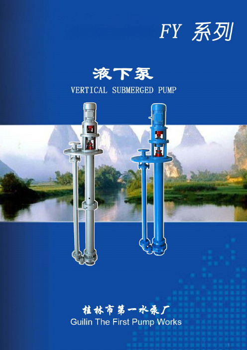
目录一、概述 (1)二、结构特点 (1)三、泵用材质 (2)四、安装说明 (2)五、使用说明 (2)六、运转及维护保养 (3)七、可能发生的故障及其解决方法 (4)八、泵结构图 (5)九、泵性能表 (6)十、泵外形和安装尺寸图 (17)十一、泵出口法兰尺寸表 (18)附表1:估计管道摩擦损失扬程用表 (19)附表2:各种阀及弯道折合直管长度 (19)一、概 述FY系列液下泵是我公司结合国内和国外先进结构自主开发的新产品。
全系列泵采用优秀水力模型,泵具有较高的效率,设计技术成熟先进,结构合理可靠,性能稳定,运转平稳。
FY系列液下泵广泛用于石油、化工、冶金等行业输送温度不高于104℃清洁或含有少量软颗粒及不易结晶的介质。
如果输送含有较多杂质或短纤维的介质,将采用开式或半开式无阻塞叶轮,泵型号标记为FYW。
对于扬程较高的泵,将采用多级液下泵的形式。
泵性能范围:流量 2 ~ 1600m3/h扬程4 ~ 132m泵型号意义:65 FY (L) (W) (D) – 40 A泵叶轮外径经一次切割,流量、扬程降低泵扬程40mFY--普通液下泵, W--污水液下泵, L--低速液下泵D—多级液下泵泵出口直径65mm二、结构特点FY系列泵属单级单吸立式液下泵,占地面积小,泵体和叶轮浸没在介质中,泵进口不需装底阀及抽真空设备就能启动工作,并且不存在轴封泄漏问题。
泵主要零件有泵体、叶轮、泵盖、轴、接管、出液管,轴承架、轴承盒、轴承套等。
液上轴承为滚动轴承。
液下轴承为滑动轴承(导轴承)。
FY系列泵属于悬臂式立式泵,液下深度越短,泵运行就越稳定可靠。
对于液下深度较深的泵,设有中间导轴承,中间导轴承的数量依液下深度的增加而增加。
中间导轴承润滑一般采用内图1 图2接自冲洗管的自润滑方式(图1),如果输送的介质较脏或含有硬颗粒则采用外接冲洗管的外润滑方式(图2)。
泵进口一般情况下不装吸入管。
如果液下深度较深,为提高泵的可靠性和运转平稳性,可以在泵的进口加吸入管。
ITT Goulds Pumps 4XD 四尺非阻塞废水泵说明书

Goulds Pumps4XDSubmersible Explosion Proof Sewage Pumps4" Non-Clog X-Proof Sewage PumpFEATURESn Impeller: Cast iron, two vane closed design for high ef-ficiency and maximum wear life. Balanced for smooth operation. Optional bronze impeller available.n Bronze Wear Ring: Replaceable to renew the running clearances and efficiencies to original conditions.n Casing: Heavy duty cast iron, volute type for maximum efficiency . 4" 125# ANSI cast iron flanged. Adaptable to guide rail mounting system.n T andem Seals: T wo independently mounted mechanical face type seals are separated by an oil filled chamber . The oil chamber acts as a barrier to trap moisture and provide time for a planned shutdown and maintenance. The oil provides lubrication to the internal (upper) seal. Carbon rotating and ceramic sta-tionary faces are standard on both internal (upper) and external (lower) seals. Optional materials are available for the lower seals. See the Nomenclature Page for order number changes to order either silicon carbide/silicon carbide faces with Viton or silicon carbide/tung-sten carbide faces with Viton elastomers. These are recommended for applications containing fine solids or abrasives as found in parking lot/garage drainage and construction dewatering jobs.n Moisture Protection System: T wo-wire, dual mois-ture sensing probes are located in the oil filled chamber between the inner and outer seals. When connected to a control panel with an optional Moisture Detection System and an alarm it will detect the presence of moisture should the outer seal fail. It will also detect moisture in the motor chamber and provide a warning prior to water levels reaching the bearing or stator .n Designed for Continuous Operation: Motor is rated continuous duty submerged condition in water that is 40ºC or below . Maximum runtime with pump unsub-merged for 7½–40 HP is 15 minutes. Motor is suitable for 10 starts per hour .n Bearings: Ball, single-row , angular contact, Conrad type bearings with a Class 3 internal fit conforming to AFBMA Standard 20 are used. The bearings are greased for life with a premium moisture resistant polyurea thickened grease containing rust inhibitors and suitable for operation over a range of – 25º C to + 120º C.n Impeller Mounting Screw: 300 series stainless steel with anti-rotational locking patch.n Castings: All iron castings are ASTM A48 class 30 gray cast iron. Optional bronze impeller is ASTM B584 C87600 silicon bronze.Goulds Pumps is a brand of ITT Engineered for life2U L UnderwritersLaboratories MOTOR LISTED EXPLOSION PROOFCLaSS I, DIvISION I, GROuPS C & DAPPLICATIONS• Sewage systems• Flood and pollution control• Industrial dewatering• Wastewater treatment plants• Municipal and subdivision lift stations SPECIFICATIONSPump:• Solids handling capabilities: 3" maximum.• Discharge size: 4" 125# ANSI flanged.• Capacities: up to 1160 GPM.• Total heads: up to 140 feet.• Minimum flow: 100 GPM.• Maximum flow: end of published curve.• Mechanical seals: 304 stainless steel metal parts, BUNA- N elastomers with carbon/rotary and ceramic/stationary faces standard for upper and lower seals. Optional lower seals are available with Viton elastomers and either silicon carbide/ silicon carbide or silicon carbide/tungsten carbide faces.• Fasteners: 300 series stainless steel.Motor:•Explosion Proof Motor: Motors up to and including 40 HP are rated as Class F, 1.15 service factor and are certified explosion proof for Class I, Division I, Groups C and D locations.•CSA certified motors (Canadian Standards Association).•UL (Underwriters Laboratories) Listed Motors.•Three phase motors only.•Available voltages: 200, 230, 400, 460 and 575 volt, 60 Hz.•HP Range: 7.5 - 40.•Motor shaft is a one-piece design of high strength 416 stainless steel.•All motors are air-filled and designed for continuous duty when fully submerged or for up to 15 minutes operation in air.•NEMA design “B” with copper windings.•Class “F” stator winding designed for inverter duty.•Moisture System: Two wire dual probe monitoring system constantly monitors seal oil chamber and stator housing for moisture. Note: control panel must contain an alarm circuit and alarm device.•Two (2) normally-closed, automatic reset thermostats connected in series and embedded in adjoining phases.•Power and sensor cords are 25’ standard length, 50’ available as an option.•Motors conform to the latest applicable requirements of NEMA, IEEE, ANSI and NEC standards.NOTICE: Class 10 quick trip overload protection must be provided in control panel.1st Character – Discharge Size4 = 4” 125 # ANSI Discharge Flange2nd and 3rd Character – Pump Type / DesignXD = Explosion Proof, Dual Seal Pump with On-Winding Thermal Sensors and Moisture Detection Sensors 4th Character – Mechanical Seals1 = Standard Seal – the upper seal is carbon/ceramic,the lower seal is carbon/ceramic, BUNA and 304stainless steel metal parts.3 = Optional Lower Seal – silicon carbide/siliconcarbide, Viton elastomers and 304 SS metal parts.5 = Optional Lower Seal – silicon carbide/tungstencarbide, Viton elastomers and 304 SS metal parts. 5th Character – Motor RPM / Hertz2 = 1750 RPM / 60 Hz 6 = 1450 RPM / 50 Hz3 = 1150 RPM / 60 Hz6th Character – HorsepowerK = 7.5 M= 15 P = 25 R = 40L = 10 N = 20 Q = 307th Character – Voltage / Phase2 = 200 /34 = 460 / 3 6 = 380/400 / 33 = 230 / 3 5 = 575 / 38th Character – Impeller CodeA = 11.0” 10 HP 1150 RPM 40 HP 1750 RPM20 HP 1450 RPMB = 10.75” 30 HP 1750 RPMC = 10.38” 25 HP 1750 RPMD = 10.12” 7.5 HP 1150 RPM 15 HP 1450 RPME = 9.75” 20 HP 1750 RPMG = 9.00” 15 HP 1750 RPM 10 HP 1450 RPM K = 8.00” 10 HP 1750 RPM 7.5 HP 1450 RPM M = 7.50” 7.5 HP 1750 RPMT = SPECIAL TRIM9th Character – Cord Length - Power and Sensor Cords C = 25’ standard F = 50’ Optional10th Character – OptionsB = Silicon Bronze Impeller E = Epoxy PaintF = Both Bronze Impeller and Epoxy PaintNOMENCLATURE DESCRIPTIONSERIES 4XD(all ratings at 3 phase, 60 Hz. Consult factory for 3 phase, 50 Hz applications.)3Goulds Pumps and the ITT Engineered Blocks Symbol are registered trademarks and tradenames of ITT Corporation.SPECIFICaTIONS aRE SuBJECT TO CHaNGE WITHOuT NOTICE.B4XD August, 2008© 2008 ITT CorporationEngineered for lifeMaximum Solid Size3"Minimum Casing Thickness 5⁄16"Casing Corrosion Allowance 1⁄8"Maximum Working Pressure 100 PSI Maximum Submergence 200 feetMaximum Environmental Temperature40º C or 104º F ambient conditions.Maximum Starts Per Hour Maximum of 10 evenly spaced starts per hour.APPLICATION DATAPower Cable Type 1/0 / 4, 2/4, 4/4, 6/4, 8/4, 10/4, 12/4 SOW or SOOW(see Model Info).Control / Sensor Cable / Type 18/5 SOW.Power Cable and Leads have a BUNA N grommet in addition to being Cap Assembly epoxy encapsulated.Power and Control 25’ standard, 50’ optional.Cable Lengths Motor Enclosure Cast iron ASTM A-48 Class 30.Motor Shaft Series 416 Stainless steel.NEMA design “B” with copper windings and designed to Motor Designwithstand 200 psi water pressure at all seal locations. Air- filled NEMA 210TY frame on 7.5, 10, 15 and 20 HP models.Air-filled NEMA 250TYS frame on 25 - 40 HP models.Motor Insulation Rating Class "F" insulation.Motor Thermal Protection Two (2) normally closed on-winding thermostats open at320º F (160º C), automatic reset closes at 221º F (105º C).Motor Overload Protection Class 10, ambient compensated, quick-trip overloadprotection must be provided in control panel.Motor Moisture Protection Two (2) moisture sensing probes in the oil-filled sealchamber must be connected to a relay in control panel.CasingCast iron ASTM A-48 Class 30.Impeller Cast iron ASTM A-48 Class 30 or optional cast bronzeASTM B584 UNS C87600.Impeller TypeTwo vane enclosed design for maximum efficiency.Casing/Impeller/Wear Ring Replaceable bronze wear ring.External HardwareStainless steel.CONSTRUCTION DETAILSSTANDARD PARTSBall BearingsLubricated for life bearings are designed for aminimum L10 life of 30,000 hours .210 and 250 FrameSingle row Radial (upper). Single row Thrust (lower).Mechanical Seals – Upper Carbon/rotary and ceramic/stationary.Standard Lower Carbon/rotary and ceramic/stationary.Mechanical Seals – Lower Silicon carbide/rotary and tungsten carbide/stationary.Optional Lower Silicon carbide/rotary and silicon carbide/stationary.Standard Motor O-rings BUNA-N (nitrile)Premium moisture resistant polyurea thickened grease Seal Chamber Oil containing rust inhibitors is suitable for operation over a temperature range of - 25º C to +120º C.DIMENSIONS(All dimensions are in inches.Do not use for construction purposes.)。
海尔 HZR12-0914DU1 母婴级中央软水机 使用说明书

一、 品牌介绍
1.1. 品牌介绍
二、 产品介绍
2.1. 产品介绍 2.1.1. 产品部件名称
2.1.2. 工作原理图
一、 品牌介绍
2.1.3. 电气原理图
2.2. 技术数据 2.2.1. 技术数据 技术数据
-2-
海尔牌 HZR12-0914DU1 型软水机
产品型号
HZR12-0914DU1
三、 使用说明.......................................3
3.1. 注意事项.......................................... 3 3.1.1. 安全方面.......................................... 3 3.1.2. 安装方面.......................................... 4 3.1.3. 使用方面.......................................... 5 3.1.4. 维护方面.......................................... 5 3.1.5. 温馨提示.......................................... 5
核心树脂材料交换容量大,交换速度快,软化效果更好,寿命更长。 • 模式定制
具有省盐模式、高效模式和假期模式,用户可按照用水情况,定制模式系 统,方便快捷。 • 逆流再生 创新的逆流再生冲洗水路设计,反冲洗效率高,均匀冲洗,耗盐量低,耗 水量更少,节水省盐,树脂再生度高。
三、 使用说明
3.1. 注意事项 3.1.1. 安全方面
6. 请勿将本设备安装于靠近酸碱性物质或气体的地方,以免对设备造成腐 蚀。请勿将本机安装在未作干湿分离处理的卫生间,以免对电路造成损 伤。
双泵双方向喷雾式奶酪泵CSD-2-H系列产品说明书

DOUBLE PERISTALTIC CHEESE DISPENSERMODELCSD-2-H SERIESInstallation andOperationInstructions2M-Z3439 Rev. H 10/17/06CSD-2-HThese symbols are intended to alert the user to the presence of important operating and maintenance instructions in the manual accompanying the appliance.RETAIN THIS MANUAL FOR FUTURE REFERENCENOTICEUsing any part other than genuine Star factory supplied parts relieves the manufacturer of all liability.Star reserves the right to change specifi cations and product design without notice. Such revisions do not entitle the buyer to corresponding changes, improvements, additions or replacements for previously purchased equipment.Due to periodic changes in designs, methods, procedures, policies and regulations, the specifi cations contained in this sheet are subject to change without notice. While Star Manufacturing exercises good faith efforts to provide information that is accurate, we are not responsible for errors or omissions in information provided or conclusions reached as a result of using the specifi cations. By using the information provided, the user assumes all risks in connection with such use.MAINTENANCE AND REPAIRSContact your local authorized service agent for service or required maintenance. Please record the model number, serial number, voltage and purchase date in the area below and have it ready when you call to ensure a faster service.SAFETY SYMBOLModel No.Serial No.Voltage Purchase DateBusiness 8:00 am to 4:30 p.m. Central Standard Time Hours: Telephone: (800) 807-9054 Local (314) 781-2777Fax:(800) 396-2677 Local (314) 781-2714E-mail ****************** ******************** *********************Website:The Star Service Help DeskAuthorized Service AgentReference the listing provided with the unit orfor an updated listing go to:Website: E-mail ********************Telephone:(800) 807-9054 Local (314) 781-2777Mailing Address: Star Manufacturing International Inc. 10 Sunnen Drive St. Louis, MO 63143 U.S.ASPECIFICATIONSDouble Peristaltic Cheese Dispenser, Model CSD-2-HCapacity: Four 6 pound bags (Four 2.7kg Bags)Electrical: 120V; 1050 Watts; 60 Cycle; single phase - or - 230V; 1050 Watts; 50 Cycle; single phaseDimensions: 18 1/4" W x 18 1/4" D x 25 3/8" H (46.3 W x 46.3 D x 64.4 H cm)Net Weight: 45 lbs. (20.4kg)CAUTIONT his equipment is designed and sold for commercial use only by personnel trained andexperienced in its operation and is not sold for consumer use in and around the home norfor use directly by the general public in food service locations.B efore using your new equipment, read and understand all the instructions & labelsassociated with the unit prior to putting it into operation. Make sure all people associatedwith its use understand the units operation & safety before they use the unit.A ll shipping containers should be checked for freight damage both visible and concealed.This unit has been tested and carefully packaged to insure delivery of your unit in perfectcondition. If equipment is received in damaged condition, either apparent or concealed, aclaim must be made with the delivering carrier.C oncealed damage or loss - if damage or loss is not apparent until after equipment isunpacked, a request for inspection of concealed damage must be made with carrier within15 days. Be certain to retain all contents plus external and internal packaging materials forinspection. The carrier will make an inspection and will supply necessary claim forms.T ANT--IMPORRead this manual completely before attempting installation.INSTALLATIONThis cheese dispenser is equipped for the voltage and wattage indicated on the nameplatemounted on the back of the unit, and is designed for use on alternating current (AC) only.NOTE: The cheese dispenser should not be installed without the four-inch (10cm) legs providedwith the machine. The legs screw into the nuts on the bottom of the dispenser.WARNINGDO NOT CONNECT TO DIRECT CURRENT (DC).GENERAL OPERATING INSTRUCTIONSThis cheese dispenser is designed to be used with a 9” x 14” (22.8 x 35.5cm) poly bag witha 1 inch (2.5cm) outlet fi tment. The peristaltic pump is designed to be used with 1/4 inch id.(.6cm) to 1/2 inch id. (1.3cm) tubing with 1/16 inch (.16cm) wall thickness.The dispenser is designed with a preset non-adjustable thermostat. It is designed to maintaina product temperature of between 140°F to 160°F.Loading Product:1. Turn dispenser OFF.2. Unhook the tension spring from the catch.3. Slide the pump block away from the pump head.4. Insert the new bag into tray and route the tube around the rollers.(NOTE: Make sure hose is not twisted)5. Place the end of the hose in the slot of the bottom bracket.6. Slide the pump block towards the pump head.7. Hook the tension spring onto the catch.8. Install the tube cover back onto the dispenser, extending the tube through the cover.Leave 1/2" of the tube below the cover.9. Dispense a small amount of product to insure the tube is seatedcorrectly, and the product is fl owing.Operation Notes:The product should be preheated according to the manufacturer’s instructions. The product should be a minimum of 140°F before dispensing.The thermometer reading will vary with the heating cycle of the dispenser over a range of 20°F. The thermometer should read between 135°F and 180°F during normal dispenser operation. Do not open the door during operation because heat will escape resulting in lower product temperature.The pump will not function correctly if the product is not at the correct temperature.The dispenser is designed to operate 24 hours a day. Once the product is placed in the dispenser it should not be removed until the pouch is empty, or the holding period of the product has expired.NOTE: To increase the evacuation of thicker products, open the dispenser and pull the product towards the outlet fi tment once or twice during operation.If the pump drips or does not dispense product check to make sure the hose is routed correctly and that the spring is latched onto the catch. Run the dispenser for a short period of time. CHECKING PRODUCT TEMPERATUREThe machine should be plugged in and turned on with product in the dispenser for a least 5 hours.1. Dispense at least 3 inches of product into an insulated cup.2. Without hesitation, insert a thermometer to the bottom of the cup and stir the product gentlywith the stem of the thermometer.3. Position the tip of the thermometer in the center of the product mass.4. The temperature should read between 140°F and 165°F.To set portion:1. Load preheated product pouch into dispenser.2. Dispense product until there is a steady fl ow.3. Dispense the product into a clean container, and measure the product to verify the dispensedamount.4. Using a small screwdriver, turn the control dial, located on the back of the unit, clockwisefor more product, and counter-clockwise for less product.5. Repeat steps 3 and 4 until the desired amount is reached.NOT E: T his dispenser control is based on a time setting. Variations in product temperature and consistency will affect the dispensed amount. To insure a consistent portion, use product that is at the correct temperature (145°F to 160°).CLEANING INSTRUCTIONSTo clean the stainless steel body:Stainless steel is corrosion resistant, but may corrode if not cleaned properly. The dispenser should be cleaned with a soft cloth with mild soap and water. Do not use detergents, strong abrasives, or metal scouring pads on the stainless steel.The pump mechanism should not need cleaning during normal use.If product should spill onto the pump head, it can be removed for easy cleaning.To remove and clean the pump head:1. Remove the bag according to the instructions.2. Unscrew the knob from the pump head.3. Remove the pump head.4. Slide the pump block out of the track.5. Clean the parts in a solution of mild soap and water using a soft cloth.6. If needed the rollers can also be disassembled for cleaning.7. Dry parts before reassembling.The spring can also be removed for cleaning by removing the retaining washer.NOTE: When installing the pump head onto the drive shaft, make sure the pump head is fully seated onto the square end of the drive shaft before installing the knob. WARNING: T he drive shaft and pump head could be damaged if the pump head is installed incorrectly.MAINTENANCE AND REPAIRSContact the factory, a service representative or a local service company for service or required maintenance.IMPORTANT: WHEN ORDERING, SPECIFY VOLTAGE OR TYPE GAS DESIREDPAGE INCLUDE MODEL AND SERIAL NUMBER OFSome items are included for illustrative purposes only and in certain instances may not be available. NumberPer UnitDescription and Model DesignationMODEL Part NumberKey NumberDouble Peristaltic Cheese Dispenser CSD-2-H 1 M2-Z1697 1 BACKM2-Z5080 1 BACKCSD-2NHC, CSD-2RCH, CSD-2RCCH 2 M2-22027 1 TOP BACK ASSY 3 2I -Z1894 2 H I NGE I NSERT 4 2T-Y5708 2 THERMOSTAT #60T13 200F5 PS-Z10007 1 MOTOR-RIGHT SIDE (no cushion required)2U-Z3000 1 MOTOR-RIGHT SIDE (120 RPM) CSD-2NHC, CSD-2RCH, CSD-2RCCH 6 2I -Y6709 4 MOTOR CUSH I ONS 7 PS-Z10008 1 MOTOR-LEFT S I DE (no cushion required)2U-Z5085 1 MOTOR-LEFT SIDE (120 RPM) CSD-2NHC, CSD-2RCH, CSD-2RCCH8 2U-Z4600 1 FAN A/C 110CFM 120V 2U-Z5041 1 FAN A/C 110CFM 230V 9 C3-39111 1 CORDSET10 M2-Z3425 1 WALL-MOTOR MOUNT 11 2K-H5417 1 BUSH I NG-HEYCO SR-6P3-4 12 2N-Z3294 1 ELEMENT F I NNED TUBULAR 120V/850W 13 M2-Z1703 2 BRACKET-ELEMENT 14 2T-Z6504 1 THERMOSTAT 147 DEG F 15 M2-22030 1 BAG HOUS I NG ASSY 16 2P-9615 2 BEAR I NG 17 2A-Z1920 2 H I NGE SLEEVE 18 2T-05-FW-0005 1 THERMOMETER 19 2B-Z1714 1 TOP SUPPORT 20 M2-22028 1 ASSEMBLY-TOP 21 M2-Z2142 1 FLANGE-TOP 22 M2-22049 1 ASSEMBLY BLOCK R I GHT 23 M2-22048 1 ASSEMBLY BLOCK LEFT 24 M2-Z1862 1 TRACK-BLOCK 25 M2-22023 1 COVER-TUBE26 M2-Z1880 1 DR I P TRAY M2-Z1868 1 DR I P TRAY CSD-2S, CSD-2CF 27 2M-Z1688 2 ARROW GRAPH I C 28 2R-Y5092 4 FOUR INCH FOOT 29 2C-Y7565 4 CAGE NUT 30 M2-Z1698 1 BOTTOM 31 2K-Y1139 6 HEYCO BUSHING SB500-6 32 2P-Z1615 1 SPR I NG-R I GHT 33 2A-H7804 4 FOOT-RUBBER 34 2C-Z1689 2 WASHER-1.25 OD X 9/32 ID 35 2P-Z1683 1 SPR I NG LEFT 36 2E-Z1622 2 SW I TCH-MOMENTARY 37 2E-Z1684 1 M I CROSW I TCH 38 2E-Y9627 1 SW I TCH-L I GHTED ON/OFF 39 M2-Z1705 1 COVER-SW I TCH LEFT 40 M2-Z1706 1 COVER-SW I TCH R I GHT 41 2A-Z1613 2 DR I VE SHAFT 42 2A-Z1690 2 COTTER PIN 1/8 X 1 1/4 43 2V-Z1619 2 PUMP HEAD44 2C-Z1620 10 SHOULDER SCREW 1" X .187 45 2A-Z1621 10 ROLLER 1 X .5ID X .194OD 46 2R-Z1623 4 KNOB-SPR I NG 47 2A-Z16162 BUSH I NG1 2IMPORTANT: WHEN ORDERING, SPECIFY VOLTAGE OR TYPE GAS DESIREDPAGE INCLUDE MODEL AND SERIAL NUMBEROFSome items are included for illustrative purposes only and in certain instances may not be available. NumberPer UnitDescription and Model DesignationMODEL PartNumberKey NumberDouble Peristaltic Cheese Dispenser CSD-2-H 48 M2-Z1701 2 MOTOR HOUS I NGMS-Z5082 2 MOTOR HOUSING CSD-2NHC, CSD-2RCH, CSD-2RCCH 49 M2-Z1702 2 MOTOR HOUS I NG OUTLETM2-Z5083 2 MOTOR HOUSING OUTLET CSD-2NHC, CSD-2RCH, CSD-2RCCH 50 2C-8477 1 TINNERMAN PUSH ON51 2I -H6579 1 GROMMET 52 M2-Z2143 1 BRACKET-CHA I N 53 M2-Z1909 1 CHA I N54 2I -Z1914 4 RUBBER PAD 55 2B-Z1869 1 GRATECSD-2S, CSD-2CF 56 2M-Z1892 1 FRONT PANEL GRAPHIC CSD-2N 2M-Z1829 1 FRONT PANEL GRAPHIC CSD-2S 2M-Z2975 1 FRONT PANEL GRAPHIC CSD-2CF2M-Z3360 1 FRONT PANEL GRAPHIC CSD-2RC, CSD-2RCH 2M-Z3362 1 FRONT PANEL GRAPHIC CSD-2RCC, CSD-2RCCH 57 2M-Z2736 2 GRAPHIC SIDE CSD-2N NONE - GRAPHIC SIDE CSD-2A2M-Z3361 2 GRAPHIC SIDECSD-2RC, CSD-2RCH 2M-Z3419 1 GRAPHIC LEFT SIDE CSD-2RCC, CSD-2RCCH 2M-Z3420 1 GRAPHIC RIGHT SIDE CSD-2RCC, CSD-2RCCH58 M2-Z5081 2 MOTOR COVERCSD-2NHC, CSD-2RCH, CSD-2RCCH592A-Z55642PUMP HEAD ASSEMBLY COMPLETE2 2STAR MANUFACTURING10 Sunnen Drive, St. Louis, MO 63143 U.S.A.(800) 807-9054 (314) 781-2777Parts & Service (800) 807-9054。
HABAR海霸泵(中国语)介绍

少 ~20 cc
气压驱动 P6, 14
1BC, 2BC Series 马达驱动
P10, 18
气压驱动 P8, 16
多
~2000cc
4HC, 5HC Series 马达驱动
P12, 20
少 ~20 cc
气压驱动 P7, 15
1BR, 2BR Series 马达驱动
P11, 19
多
~2000cc
气压驱动
http://www.unicontrols.co.jp
)1
Products Guide
海霸泵产品资料
B 系列〈气动〉
CV 型 RV 型
H 系列〈气动〉
CV 型 RV 型
B 系列〈电动〉
CV 型 RV 型
H 系列〈电动〉
CV 型 RV 型
Option
可选配件 客户订制产品
构成泵的所有的零部件 全部是自己公司生产。 组装 · 检验 · 试验都是在 严格的质量管理体制下进行的, 所以才可以向世界提供高精度高品质的产品
往复 / 分
ℓ/ 分
总长 总宽 总高
6.9
197
180 次
13.8
43
88
203
120 次
16.5
267 50
94
重量 kg 2.3
3.6
管径(inch)
吸入
吐出
1/8” 1/8”
1/4” 1/4”
3/8” 1/4”
1/2” 3/8”
6 Precision Pump Products Guide
B Series R V otary alve Type
Reciprocating Drives (Servo Driven)
- 1、下载文档前请自行甄别文档内容的完整性,平台不提供额外的编辑、内容补充、找答案等附加服务。
- 2、"仅部分预览"的文档,不可在线预览部分如存在完整性等问题,可反馈申请退款(可完整预览的文档不适用该条件!)。
- 3、如文档侵犯您的权益,请联系客服反馈,我们会尽快为您处理(人工客服工作时间:9:00-18:30)。
12LBSA-54立式斜流泵
斜流泵又叫做导叶式混流泵,具有占地面积少、外径小、易启动以及效率高等优性,是一种性能和结构介于离心泵和轴流泵之间的水泵,补偿了两者的缺点同时具有两者的优点,。
斜流泵的比转速在290~590,目前其应用范围也开始逐渐向其他泵类产品的领域拓展。
TKX(S)、LKX(S)、LBX(S)型立式斜流泵,适合作大型火电站和核电站的循环泵,作冶金、城市和农田给排水和工矿工程泵,用来输送55℃以下的清水、雨水、污水以及海水。
12LBSA-54立式斜流泵型号说明:
80LKXC-20A
80-泵的吐出口径(寸,即2000/25=80)
L-表示立式斜流泵,T表示叶片可调;
K-表示泵转子可抽出,B表示转子不可抽;
X-表示泵吐出口在基础层之下,S表示吐出口在基础层之上;
C-泵的设计顺序;
20-泵设计点扬程;
A-表示叶轮经过切割。
12LBSA-54立式斜流泵数据参数:
流量Q 0.20~25m3/s
扬程H 3~60m
12LBSA-54立式斜流泵结构型式:
立式斜流泵轴均为立式安装,吸入口垂直向下,吐出口水平外伸,转子部件有可抽出式和不可抽出式两种形式。
T型泵的叶轮片叶片角度可在机组运行中进行改变。
安装方式有泵、电动机分别安装在两个基础层和泵、电动机直联安装在一个基础层两种形式。
密封用填料密封。
泵的吸入水池有湿坑式和干坑式两种。
立式斜流泵的轴向推力一般由电动机承受,小型立式斜流泵也可由泵自身承受。
叶轮通常为一级,根据需要也可设计成多级。
立式斜流泵的轴承采用橡胶轴承和赛龙轴承两种,当采用橡胶轴承时,泵轴设有保护套管,内心清洁压力水进行润滑。
12LBSA-54立式斜流泵零件材质:
立式斜流泵泵轴为优质碳素钢。
叶轮为铸铁或铸钢或不锈钢。
其余为铸铁,或钢板焊接。
12LBSA-54立式斜流泵成套范围:
成套供应泵,电动机和底座或安装垫板。
12LBSA-54立式斜流泵性能参数:
参数 型号
流量Q 扬程H 转速n 轴功率Pa 配带电动机效率η必须汽蚀余量叶轮名义直径吐出
口径泵重功率
型号
m 3/s m r/min kw kw %
m
mm mm t 12LBSA-400.18
0.24
0.2940.438.034.5980102.0111.8121.8160
YLST355-6W 70.079.081.0 5.10
5.30
6.70558
300
6.1
12LBSA-440.21
0.27
0.32
44.0
40.034.51480116.7
131.8138.0160
YLST355-477.081.079.67.409.0010.90434
300
3.8
12LBSA-540.16
0.18
0.28
56.5
54.046.01480113.4
121.3173.6
185
YKSL355-4W 76.080.072.0 3.00
3.60
446
300
4.0
14LBSA-160.28
0.33
0.39
19.0
16.0
14.0
1480
64.7
61.9
61.3
90YLST280M-4
80.0
87.0
87.1
5.90
6.70
7.10
362.6350 4.5
12LBSA-600.22
0.31
0.36
64.0
55.0
47.0
1480
181.9
202.3
207.5
250YKSL355-4W
80.5
85.5
84.2
8.10
8.90
9.30
481.43507.0
16LKXA-160.39
0.44
0.50
20.0
17.8
16.3
1480
84.0
85.0
80.0
112YLST355S-4
80.0
84.0
78.0
4.20
5.00
6.50
393.47400 5.0
16LBSA-200.34
0.36
0.45
20.5
20.0
18.3
980
85.3
89.8
96.1
132YLST315L2-6
80.0
83.0
84.0
4.30
4.40
4.90
450.88400 3.5
16LBSA-300.31
0.36
0.40
37.5
33.0
30.0
980
142.0
142.4
146.2
185YKKL355-6W
79.0
82.0
81.0
5.10
5.70
6.50
579.8400 4.8
16LBSA-450.35
0.40
0.49
47.4
45.0
39.1
980
196.2
207.7
218.6
250YKSL450-6
82.3
85.0
85.3
6.60
6.80
7.40
617.5400 4.3
16LBSA-470.28
0.35
0.39
51.7
47.0
43.0
1480
189.5
203.8
214.9
250YKSL355-4W
74.3
78.5
76.3
6.83
8.01
9.50
462.1400 5.0
16LBSA-650.44
0.56
0.58
78.2
65.0
61.0
1480
399.4
416.6
414.2
500YKKL500-4
85.4
85.0
84.2
7.60
11.40
12.00
579.8400 4.2
20LBSA-200.44
0.56
0.67
22.8
20.0
15.6
980
122.3
129.9
139.6
185YKSL355-6W
81.3
83.9
73.1
4.88
5.38
7.78
450.9500
5.5。