HP StorageWorks EVA4400 M6412 drive enclosure installation instructions
EVA4400配置
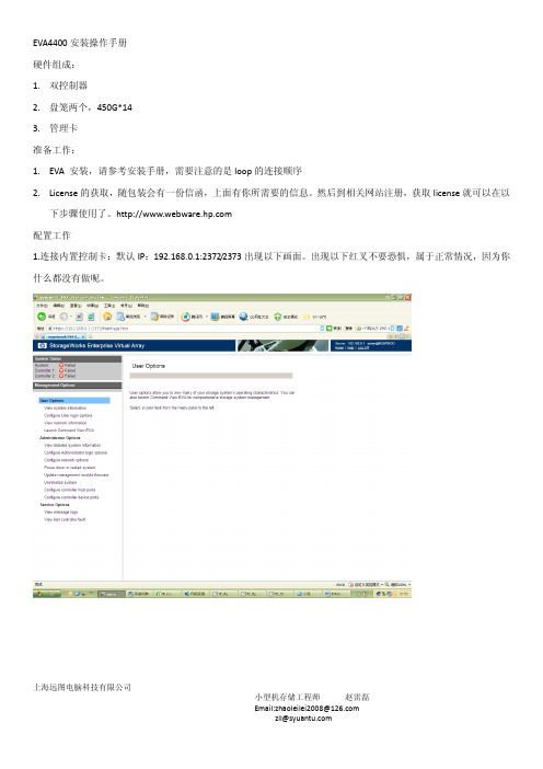
上海远图电脑科技有限公司EVA4400安装操作手册 硬件组成: 1. 双控制器2. 盘笼两个,450G*143. 管理卡 准备工作:1. EVA 安装,请参考安装手册,需要注意的是loop 的连接顺序2. License 的获取,随包装会有一份信函,上面有你所需要的信息。
然后到相关网站注册,获取license 就可以在以下步骤使用了。
配置工作1.连接内置控制卡:默认IP :192.168.0.1:2372/2373出现以下画面。
出现以下红叉不要恐惧,属于正常情况,因为你什么都没有做呢。
上海远图电脑科技有限公司2.登陆COMMOND VIEW ,找到这个选项,点击进入Commond View 操作界面3.页面提示信息可以看到没有安装license 许可呢,我们要做的是先初始化系统。
上海远图电脑科技有限公司4.填写好相关的参数,执行初始化操作上海远图电脑科技有限公司5.新系统,初始化很快,3分钟左右已经完毕上海远图电脑科技有限公司6.看到提示,需要安装LICENSE上海远图电脑科技有限公司7.在如图所示的对话框中,把你申请的license 许可码黏贴到其中,注意不要多余的符号8.我的是无限制容量的licesen,贴上来吧,但是不怕抄袭,因为是跟wwn 号绑定的。
点击install license 按钮,瞬间可以安装完成上海远图电脑科技有限公司9.现在可以看到如下图的内容,说明应经安装成功,刷新一下,就可以继续接下来添加VDISK 、HOSTS 等操作了.下面我们要做的是配置HOSTS,VDISK 并且present 到相关的主机 1.用户名:admin 密码为空上海远图电脑科技有限公司1.在HOSTS 中,如果主机很多,可以创建相关的文件夹。
如我所创建的RX66002.在创建的hosts 文件夹中可以添加相关的host,ADD HOST上海远图电脑科技有限公司3.可以给hosts 起一个通俗易懂易于辨认的名字,根据自己的需要选择配置参数,如果不知道参数有什么用,可以选择后面的小问号查看参数解释。
HPStorageWorks磁碟阵列解决方案
HPStorageWorks磁碟阵列解决方案儲存伺服器解決方案67HP StorageWorks磁碟陣列解決方案HP儲存資源最佳化解決方案提升儲存的效能、效率與永續性各企業大量利用IT以改善其自身的經營績效,IT能力的良窳已經是企業策略性的競爭優勢。
在多年來各式應用程式及IT設備的引入,企業內累積了大量的資料,儲存在各式各樣的儲存設備上,以提供各個關鍵性應用程式所使用。
資料的儲存、存取、保護及歸檔不但是企業內IT部門重要的工作,其運作的效率及效能,更直接影響企業每日的正常運作。
以下將整理出3種企業內使用儲存設備最常運見的使用情境及HP 相對應的解決方案,以提供確實可行的架構及產品,來解決每一情境的問題與挑戰。
這些解決方案包括:HP儲存整合解決方案(Storage Consolidation Solution)HP儲存/網路整合解決方案(Storage/Network Consolidation Solution)HP儲存虛擬化解決方案(Storage Virtualization Solution)6869儲存伺服器解決方案效益:1. HP 完整SAN 儲存裝置,提供符合各種不同需求的性能價格比2. HP 有共種不同領域及不同應用程式的技術顧問,可針對整合架構作專業規劃3. 整合不是一蹴可及,HP 有完整的Roadmap 可引導客戶階段性的完成整合專案典型組態包含如下組件:1. HP StorageWorks EVA 、XP 磁碟陣列或LeftHand 產品2. SAN Director 或HP ProCure 交換器3. HP 儲存整合專業服務及專案管理二、NAS (Network Attach Storage )問題與挑戰:1. 檔案分散,整合不易2. 檔案容量成長快速,磁碟空間不敷使用3. 不同的NAS ,操作及管理均不相同4. 企業內同時擁有多套NAS 時,系統管理者需面對複雜的檔案版本控管、檔案更新、檔案重複及同步、檔案安全設定、使用者帳戶管理、備份、…等多個複雜議題5. 針對應用程式的效能調校HP NAS 解決方案,包括簡單易用的X1000系列,基於標準x86架構及Microsoft Storage Server 的ProLiantStorage Server 及叢集式高效能的EFS Clustered Gateway 。
HP存储产品介绍

EVA存储新特性
● 采用新型1TB FATA硬盘时最高容量可达240TB。 采用新型450GB 15K高性能FC硬 盘时最高容量可达108TB ● 经过工厂配置的EVA8100选件可在同一个机架内支持多种产品。 当前的EVA EVA8100 SKU支持以存储为中心的配置。 全新的EVA8100 2C2D和2C6D SKU支持多 种产品-服务器、存储和备份设备可与EVA共同安装在一个机架内。 ● 全新的异构光纤通道SAN支持Apple Mac OS X ○ ○ 面向Apple Mac OS X的从1TB到120TB可扩展的企业级存储支持 本地复制支持
• ease of administration • price/scalability
Scalability
HP存储低端产品 HP存储低端产品
MSA 存储阵列: 存储阵列: HP StorageWorks 2000fc 模块化智能阵列(new, 光纤) 模块化智能阵列( 光纤) HP StorageWorks 2000i 模块化智能阵列 (new,iSCSI) ) HP StorageWorks 1500cs 模块化智能阵列 (光纤) 光纤) HP StorageWorks 1000 模块化智能阵列 (光纤) 光纤) HP StorageWorks 1510i 模块化智能阵列 (iSCSI) ) MSA 磁盘机箱 HP StorageWorks HP StorageWorks HP StorageWorks HP StorageWorks HP StorageWorks HP StorageWorks
灵活、可扩展的 灵活、可扩展的 灵活、可扩展的 SCSI驱动器机箱 灵活、可扩展的 营销声明 外部存储解决方 外部存储解决方 外部存储解决方 外部存储解决方 案 案 案 案 25个SAS磁盘 12个SAS磁盘 10 14 12个SATA磁盘 磁盘驱动器总数 磁盘驱动器总数 25个SATA磁盘 最大存储容量 3.6TB 12个SATA磁盘 9TB 每个机箱1.4TB (使用146GB 10K 磁盘驱动器,在 2U配置中可提供 28 TB的存储容量) 2TB 9TB 最大存储容量
HP StorageWorks EVA软件兼容性参考说明书

Y
Y
HP StorageWorks Replication Solutions Manager 1.0 and later
Y
Y
HP StorageWorks Command View
EVA 3.3 and later2
Y
Y
Y
Y
Y
Y
Y
Y
Y
Y
HP StorageWorks Secure Path (required for multipath configurations)
Storage Management Appliance
G1, G2, G3
HP ProLiant Storage Server
HP ProLiant DL380 G4 Storage Server (base model) HP Proliant DL380 G4 Storage Server (SAN model) HP ProLiant DL585 Storage Server HP Proliant DL585 Dual Core Storage Server Note: In most configurations, the HP ProLiant DL380 SAN model is preferred.
Y
Y
Y
SSSU Build 7 for 3.2
HP Command View EVA 4.0
EVAPerf 1.0 SMI-S EVA 4.0
N
Y
N
SSSU 4.0.18
EVA3000/EVA5000 VCS 3.0141 VCS 3.0202
Y
Y
Y
Y
Y
Y
磁盘存贮器(HP eva4400)详细需求

容量
本次配置容量=18TB,最大容量可扩展至96TB
IPOS
140000
支持主机个数
256
客户端支持
不收费
带宽
>=1550MB/s
最大Raid集
最大RAID集的磁盘数量≥16
是否OEM
需要原厂商设备,非OEM产品。
操作系统
控制器采用专用操作系统(非Windows、linux的改造版)
磁盘混插
在同一硬盘笼内实现FC和ATA硬盘混插
磁盘存贮器(HP eva4400)详细需求
指标
描述
品牌
HP
机型
全光纤架构SAN磁盘阵列
阵列控制器
标配2个RAID控制器实现冗余,采用Risc处理器。
阵列高速缓存
当前配置阵列高速缓存必须满配且数量=4GB
后端接口类型
FC:4(4Gb)
后端通道数量
4
最大硬盘个数
最大硬盘个数>=90
硬盘可靠性
在有冗余硬盘空间的情况下,同一个Raid组中,支持超过2块以上的硬盘渐次损坏
后端交换架构
磁盘阵列使用交换架构连接后端磁盘抽屉
主机连接
在阵列允许的情况下,不限制安装主机数量,未来增加任意平台,任意主机数量不需要额外付费。如需付费,请投标时配齐。
RAID支持类型
支持VRAID0,VRAID1,VRAID10、VRAID5
EVA企业级虚拟磁盘阵列

May 10th 2005
EVA8000 体系结构
EVA管理 平台 (Win)
Fabric 1
Fabric 2
• 2 HSV 控制器 • 4 FC内部光纤环路交换机
HSV210 controller 1
FC loop switch FC loop switch
Copyright © 2005 HP Peter Mattei
21
EVA4/6/8000安装维护
May 10th 2005
Copyright © 2005 HP Peter Mattei
22
EVA4/6/8000的连接
•
EVA4/6/8000 存储系统是基于SAN 的架构的,因 此在与主机相连时必须要通过SAN switch连接。 与EVA3000/5000不同的是,EVA4/6/8000开始支 持主机FCA与EVA直连,但是目前只适用于安装 windows的主机。 在基于性能和安全的考虑下, 在做系统设计时,我们强烈建议使用双光纤交换机、 主机使用双FCA卡以确保系统的高可用性。下图为 一个无单点故障的系统连接示意图和EVA光纤连接 图示意图:
•
•
May 10th 2005
Copyright © 2005 HP Peter Mattei
2
企业级虚拟化磁盘阵列EVA4000
•
• • •
•
•
•
虚拟RAID: Vraid0, Vraid1, Vraid5 每个EVA4000包含 2GB 数据缓存和2GB 系统缓存 4 主机端口 内部双光纤环路与磁盘柜连接 − 72, 146, 300GB 光纤磁盘 − 250GB FATA 磁盘 灵活的磁盘配置 − 1 到 4 个磁盘柜 − 8 到 56 磁盘 − 最多支持 16.8TB 性能 − 141‘000 IOPs − 335 MB/s 支持的平台
EVA4400
HP StorageWorks 4400企业虚拟阵列(EVA4400)性能白皮书简介 (2)性能参数 (2)端到端性能参数 (3)高速缓存性能参数 (3)EVA4400性能参数总结 (3)EVA4400和EVA4100的差别 (3)测试环境说明 (4)评估标准 (4)测量结果 (5)结论 (8)更多信息 (8)简介HP StorageWorks企业虚拟阵列(EVA)系列产品为大中型企业客户提供了具备领先性能、大容量和高可用性的存储解决方案,可显著降低IT成本及复杂性。
EVA提供了存储虚拟化功能,可实现虚拟存储池、简化管理、自动性能负载平衡、动态容量管理等特性。
HP StorageWorks 4400企业虚拟阵列(EVA4400)继承了所有这些先进特性。
由于工程设计方面的改进,EVA4400在实际环境中的性能大大超过了EVA4100。
由于持续读写性能得到大幅提升,EVA4400显著提高了各种应用的I/O处理能力,包括数据仓储、流媒体、高性能技术计算以及备份和恢复等。
在随机读写性能方面,EVA4400的整体性能可随磁盘数量的增加而增长。
客户可以根据实际业务情况,预先选择最佳的配置。
随机读写性能的提高也改进了各种应用的吞吐量并缩短了响应时间,其中包括文件系统、面向交易的数据库以及电子邮件等。
本文对以下两方面进行了概括:•高速缓存和端到端性能参数的重要性和区别•EVA4400性能概述性能参数HP StorageWorks的研发工作以两项重要原则为指导:•开发出的产品必须能为客户创造价值,符合其质量要求。
(这条原则始终为惠普公司在尖端技术部署的决策提供指导。
)•通过可靠的测试程序建立信任,在正常的工程设计限制内,客户可以在自己的公司内使用这些程序进行反复的测试。
(许多客户将惠普视为“可信任的顾问”,并依赖惠普技术来运营他们的企业。
他们可以在自己的站点,通过测试程序反复进行验证,确认惠普的产品是否符合要求。
hpeva4400存储配置手记
hpeva4400存储配置手记HP EVA4400作为一款企业级的核心数据存储系统,不仅性能优良而且配置简便。
凭借其广泛的操作系统支持,以及与Microsoft Exchange、Oracle及SAP等应用的优良集成,EVA4400以其出色的技术和节约成本成为企业存储解决方案的可靠之选。
下面就给大家介绍一下它的配置和基本应用,方便大家在工作中学习和掌握它。
HP EVA4400存储系统是基于SAN 的架构, 因此在与主机相连时一般要通过SAN Switch连接, 当然EVA也支持与主机FC HBA的直连; 在做系统设计时, 我们建议使用双光纤交换机、主机使用双FC HBA 卡以确保系统的可靠性。
下图所示为一个单HSV300加上单磁盘柜的EVA系统连接示意图HP EVA4400由HSV300控制台和磁盘柜(可扩展)两部分硬件组成。
一、初始化HP EVA系统需要有一台PC服务器专门用来管理EVA,这台PC 服务器被称为Storage Management Appliance,简称SMA,当然也可以通过 EVA4400 本身 management module 进入,登陆方法:登录名:admin,密码为空二、创建VDISK点击图中“Virtual Disks”处, 在右侧的内容栏点击“create vdisk ”属性页创建 VDISK,输入相应参数然后点击“完成”按钮。
也可创建VDISK Group,然后在磁盘组中增加 VDISK。
如果需要创建多个虚拟磁盘,还可以继续点击创建即可。
补充:VDISK RAID类型,可以分为Raid0、Raid1、Raid5、Raid6Raid0是没有任何冗余的,任何一个物理磁盘损坏, 都会导致数据的丢失,因此不建议采用,但是 Raid0的磁盘利用率可以达到 100%Raid1是镜像方式做的冗余,Raid1的磁盘利用率只能达到 50%Raid5是采用4+1备份做的冗余,磁盘利用率只能达到 80%Raid6和Raid5一样对逻辑盘进行条带化然后存储数据和校验位,只是对每一位数据又增加了一位校验位。
HP EVA卖点、解决方案、竞争分析介绍
9
2011年12月1日星 期四
惠普新一代存储产品 StorageWorks EVA4400/6400/8400
内容
• • • •
惠普EVA产品卖点 惠普EVA解决方案 竞争分析 Q&A
50’000th EVA sold in July 2008
The EVA success story
60’000th EVA sold in Dec 2008
虚拟化阵列控制器Virtual selection Controller
0 1 2 3 4
LUN 0 LUN 2 LUN 4 LUN 3
1 2 3
LUN 1
热 备 份 盘 热 备 份 盘
Vol 0
Vol 1
Vol 2
Vol 3
Vol 4
Vol 1 Vol 2
EVA的虚拟化技术 的虚拟化技术 无需预先分配自由空间 自由 自由空间对已有卷或新 建卷可用
EVA4400
HSV300/300-S 2u - dual controllers 4GB 8 / 96
EVA6400
HSV400 4u - dual controllers 8GB 8 / 216 32TB M6412A 2 /18 72GB 146 / 300 / 450GB 400 / 450 / 600GB 1000GB 2048
7
data10 data9 parity8 data7 data6 data5 data4 parity3 data2 data1
EVA4400_产品介绍
惠普新一代虚拟化阵列 StorageWorks EVA4400惠普增值渠道部内容• • • •惠普存储产品市场定位 惠普EVA4400隆重登场 惠普EVA的核心技术 基于惠普EVA的完整存储解决方 案惠普存储产品家族提供存储业界最全面的产品和解决方案存储网络 设备光纤交换机 存储服务器 EFS Cluster Gateway多协议路由 /FCIP/iSCSI All-in-One MSA EVAHBA卡 XP存 储 解 决 方 案 及磁盘阵列和 NAS产品 产品磁带 磁带机/Autoloader D2D备份 虚拟磁带库MSLEMLESL原 厂 服 务磁带和磁盘 备份产品存储软件惠普磁盘阵列市场定位XP系列新!EVA系列EVA4400整合和性能新!MSA系列XP20000 < 177TB+ TB XP24000 < 851TB + TB一体化存 储系列MSA2000出众的TCO < 240TB 低成本整合 < 36 TB4Gb FC和1Gb iSCSI SAS与SATA一起 • 基于控制器的快照/克隆 • Windows、Linux、VMware • WEB、Exchange、SQL• •始终在线的可用性 < 851TB + TB• • • • • •简单的统一存储 < 12 TBiSCSI SAN和优化的NAS,具有 集成的快照、备份、复制和简易 管理特性 • Windows, Linux, VMware等•FC & iSCSI主机端口 FC和FATA硬盘 • 存储整合+ 灾难恢复 • 通过虚拟化实现简化 • Windows、HP-UX、Linux等 操作系统• •FC、FICON和ESCON主机端口 FC和SATA硬盘 HP-UX、Windows等20多种操作系 统,包括NonStop和大型机 数据中心整合 + 灾难恢复 大型Oracle/SAP应用 HP-UX、Windows等20余种操作系 统,包括NonStop和大型机业务连续和可用性4 2008年4月21日 星期一EVA4400盛大发布 EVA4400盛大发布EVA4400的新特性2008年3月4日发布/发货 定位于10万至30万人民币的价格区间 99.999%的可靠性源于业界独有的EVA后端全交换式架构 业界第一个8GB Ready阵列产品; 可扩展96块磁盘; 全新400GB/450GB/1000GB磁盘。
- 1、下载文档前请自行甄别文档内容的完整性,平台不提供额外的编辑、内容补充、找答案等附加服务。
- 2、"仅部分预览"的文档,不可在线预览部分如存在完整性等问题,可反馈申请退款(可完整预览的文档不适用该条件!)。
- 3、如文档侵犯您的权益,请联系客服反馈,我们会尽快为您处理(人工客服工作时间:9:00-18:30)。
HP StorageWorks EVA4400 M6412drive enclosure installation instructions20082008*5697-7403*About this documentThis document describes how to install an M6412drive enclosure into a cabinet as part of an EVA4400storage array.The drive enclosure installation may be performed while the array is in operation.These instructions cover the following topics:•Before you begin,page1•Kit contents,page1•Attaching the rails,page2•Installing the drive enclosure,page3•Cabling the enclosure,page4•Cabling the enclosure while offline,page4•Cabling the enclosure while online,page5•Alternate enclosure cabling,page6Before you beginRead the following warnings and cautions before installing the driveenclosure.Make sure that the rack is sufficiently stable.If provided,lowerthe cabinet leveler feet and make sure any required stabilizersare installed.If provided,extend the rack anti-tip device.Failureto extend the anti-tip device could result in personal injury ordamage if the cabinet tipsover.Make sure that the cabinet and all equipment mounted in thecabinet have a reliable ground connection.Verify that the totalcurrent of the cabinet components does not exceed the currentrating of the power distribution unit or the power distributionmodules.Parts can be damaged by electrostatic er properanti-static protection.For additional information,see thedocumentation that shipped with your system.Kit contentsCheck the kit contents to make sure you have the items listed in Figure1.1Drive enclosure5Rails with –03brackets 2Eight disk drive blanks (may comepreinstalled inenclosure)6Two Fibre Channel copper cables3–04brackets (not used)7Two enclosure power cords4Pins for round-hole cabinet conversionFigure 1Kit contentsAttaching the railsThe cabinet rail kit supplied with the drive enclosure comes con figured for square-hole cabinets.If you need to convert the rails for a round-hole cabinet,perform the following steps:Do not remove the pins from the ends of the cabinet rails unless you are converting the rails for use in round-hole cabinets.These load-bearing pins are designed to fit throughthe holes without being removed.1.Locate the bag of eight round-hole pins that is included in thecabinet rail e a No.2Phillips screwdriver to remove the standard pins fromthe front and back of the left and right rails (four on each rail).See Figure 2.Figure 2Square hole to round hole cabinet conversion 3.Attach the round-hole pins into the eight holes on the rails wherethe standard pins were removed.To attach the rails to the cabinet:The designation of left and right rail is made when looking at the front of the rack.The rails are marked by an R (right)and L (left)stamped on the metal.1.Insert the rear end of the right rail into the inside back ofthecabinet until the pins partially extend through the holes in the cabinet upright.2.Squeeze the scissors latch together to insert the rail and pins thoughthe cabinet upright holes until the latch engages.See Figure 3.3.gl0124Figure8Tighten drive enclosure to cabinet 4.Reattach the front bezel covers.5.At the rear of the cabinet,slide the shipping retaining bracketforward on both rails until the tab engages the slot in the drive enclosure.Tighten the bracket thumbscrews.6.Populate the enclosure with available disk drives (not included withthis kit),starting with the lowest number in Figure 9,and continuing in order until you have inserted the desired number.If installing multiple drive enclosures,balance the quantity and sizes of disk drives between the enclosures as evenly as possible.Figure 11Inserting a drive blankCabling the enclosureTwo methods are described for cabling a new drive enclosure.The online method allows a drive enclosure to be added to a powered operational array.The of fline method describes cabling an array that has been powered down.The of fline method is preferred if downtime is available.One controller enclosure (with two controllers)can support up to eight drive enclosures.The power cords are supplied in two different colors should you decide to use the colors to denote sides of the cabinet.For example,you can locate all gray power cords on the left side of the cabinet,and all black power cords on the right side.for preexisting cabling when another of the array.dashed between the drive enclosures show cables that are added.Unplug the Fibre Channel cable from I/O module A port P2of the drive enclosure nearest the newly installed drive enclosure,and plug it into the P2port of I/O module A of the newly installed drive enclosure (1,Figure 13).This should be a long cable with the far end connecting to controller 2port DP1–A in a con figuration with all the drive enclosures installed above or below the controller enclosure.If drive shelves are installed above and below the controller enclosure,see Figure 14.gl012212341Connects installed I/O module A,port 2to controller 2,port DP1–A2Connects installed I/O module A,port 1to existing I/O module A,port 23Connects installed I/O module B,port 2to controller 1,port DP1–B4Connects installed I/O module B,port 1to existing I/O module B,port 2Figure 13Addition of drive enclosure to arraying a Fibre Channel copper cable provided in your kit,plug oneend into the P2port of I/O module A that was unplugged in the previous step,and plug the other end into port P1of I/O module A in the newly installed drive enclosure (2,Figure 13).4.Perform steps 2and 3on I/O module B of the newly installed driveenclosure.The results are the Fibre Channel cable on I/O Module B port 2of the nearest drive enclosure is moved to I/O module B port 2of the newly installed drive enclosure (3,Figure 13).In addition,a new Fibre Channel copper cable is installed between I/O Module B port P2of the preexisting drive enclosure and I/O module B port 1of the newly installed drive enclosure (4)ing a power cord provided in your kit,plug one end into a driveenclosure power supply and the other end into a cabinet power distribution module.6.With the remaining power cord,connect the other power supply toa cabinet power distribution module.7.Press the Power On/Standby button on the power UID bezel(located at the rear of the drive enclosure)and hold it down long enough to power up the installed enclosure.8.Power on any other drive enclosures attached to the array andvisually check that the enclosures power on without errors.Wait at least one minute after all the enclosures are powered on for the drives to spin up and stabilize.9.Power on the controller enclosure by pressing the power button onthe power UID bezel until the enclosure responds (it may take up to 10seconds for the controller enclosure to power on).Wait five minutes for the array to stabilize.10.Verify that I/O modules A and B on the added enclosure havebeen assigned an index number of the next higher enclosurenumber.For example,if the previous highest index number was “3,”then the installed enclosure should display “4.”11.In HP Command View EVA,verify that the newly installed driveenclosure appears in the array hardware pane,and that the I/O modules show a good operational status.Cabling the enclosure while onlineing a power cord provided in your kit,plug one end into thedrive enclosure power supply and the other end into a cabinet power distribution module.You will brie fly hear a rush of air as power is applied,and the LEDs on the power UID flash.The power UID standby switch LED remains amber.2.With the remaining power cord,connect the other power supply toa cabinet power distribution module.The power UID power switch LED turns green.The I/O module index number will likely display 00,but if not,ignore the index number at this time.3.Figure 12shows the cabling for an array with one controllerenclosure and three drive enclosures.As a general cabling guideline,the P1port on the I/O module receives input from another I/O module or a controller,and the P2port is used for output to another I/O module or controller.In the steps performed below,one side of the drive enclosure (ports P1and P2of I/O module A on the left side)is cabled,and then I/O module B is cabled.Either I/O module can be cabled first as long as the other I/O module ports are not unplugged until cabling is complete on the first I/O module.This allows the controller to redundantly manage the storage while the cables are brie fly pulled and reconnected on one side.4.Figure 13shows the cabling when another drive enclosure isadded to the bottom of the array.The dashed lines leading to the controller enclosure show cables that are moved,and dashed lines between the drive enclosures show cables that are added.Unplug the Fibre Channel cable from I/O module A port P2of the drive enclosure nearest the newly installed drive enclosure,and plug it into the P2port of I/O module A of the newly installed drive enclosure (1,Figure 13).This should be a long cable with the far end connecting to controller 2port DP1–A in a con figuration with all the drive enclosures installed above or below the controller enclosure.If drive shelves are installed above and below the controller enclosure,see Figure 14.ing a Fibre Channel copper cable provided in your kit,plugoneend into the P2port of I/O module A that was unplugged in the previous step,and plug the other end into port P1of I/O module A in the newly installed drive enclosure (2,Figure 13).Wait for the port to become visible with HP Command View EVA.With only one I/O module from the newly added enclosure cabled to the array,there will be HP Command View EVA warnings that indicate disk drives in the system are onlyconnected on one of the redundant Fibre Channel loops.This is to be expected,and the warnings should clear as soon as the other I/O module is connected.6.Perform steps 4and 5on I/O module B of the newly installed driveenclosure.The results are the Fibre Channel cable on I/O Module B port 2of the nearest drive enclosure is moved to I/O module B port 2of the newly installed drive enclosure (3,Figure 13).In addition,a new Fibre Channel copper cable is installed between I/O Module B port P2of the preexisting drive enclosure and I/O module B port 1of the newly installed drive enclosure (4).7.Verify that I/O modules A and B on the added enclosure havebeen assigned an index number of the next higher enclosurenumber.For example,if the previous highest index number was“3,”then the installed enclosure should display“4.”8.In HP Command View EVA,verify that the newly installed driveenclosure appears in the array hardware pane,and that theI/O modules show a good operational status. Alternate enclosure cablingDrive enclosures may have to be installed where room is available in a cabinet.Figure12and Figure13show drive enclosures mountedin a cabinet on just one side of the controller enclosure.When drive enclosures are mounted on both sides of the controller enclosure,the cabling is logically the same,in that all the drive enclosures are connected serially.In this case,the long Fibre Channel cable goes from the I/O module P2port of the last drive enclosure on one sideof the controller enclosure to the farthest drive enclosure on the other side of the controller enclosure.The last drive enclosure in the series (near the controller enclosure)completes the loop back to the controller. Figure14shows this cabling configuration with drive enclosures above and below the controller enclosure in an array.Installing a drive enclosure above or below this configuration would keep the same pattern of cabling between the drive and controller enclosures.gl0125 Figure14Array cabling for drive enclosures on both sides of the controller enclosure。