A ”Dual-Tree” Scheme for Fault-Tolerant Multicast
IEEE_802.17

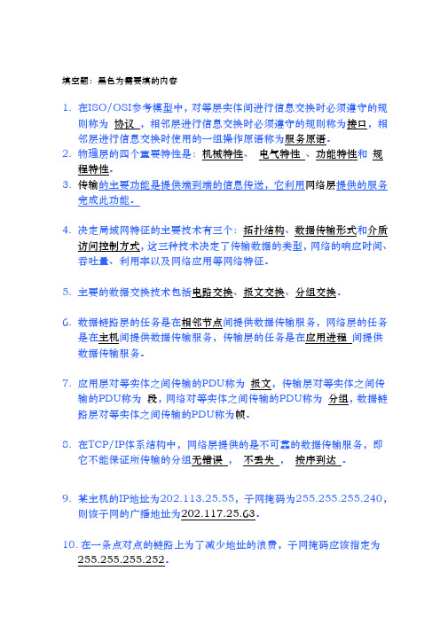
MAC datapath sublayer
MAC Address match – Receive, strip Multicast – Copy, transit Expired TTL - strip Else - Transit
Transit buffer Single queue or Dual queue
Key: MAC – Medium access controller PHY – Physical layer entity RS – Reconciliation sublayer Version 1.0 IEEE 802 March 2011 workshop
MAC
MAC Datapath
PHY RS
4
Version 1.0
payload
EEE 802
Page 9
IEEE 802 March 2011 workshop
IEEE Std 802.17 Datapath sublayer
MAC service interface
Fairness algorithm, OAM, Protection, Topology
Agnostic to which PHY used RS defined for SONET/SDH and 1 and 10 Gbps Ethernet PHYs
West PHY
MAC
RPR Station
PHY
MAC Datapath
MAC
Must be same speed on all links Media can be different
IEEE Std 802.17 Resilient Packet Ring (RPR)
网络系统建设与运维(中级)习题

网络系统建设与运维(中级)习题第1章一.单选题1.OSI参考模型中,从下往上的层次依次是?()A.物理层→传输层→数据链路层→网络层→会话层→表示层→应用层B.物理层→传输层→数据链路层→网络层→会话层→应用层→表示层C.物理层→数据链路层→传输层→网络层→会话层→应用层→表示层D.物理层→数据链路层→网络层→传输层→会话层一表示层→应用层2.在TCP/P模型中,“帧”是第几层的数据单元?()A.XXX3.ARP的主要功能是()。
A.将IP地址解析为物理地址B.将物理地址解析为IP 地址C.将主机名解析为IP地址D.将IP地址解析为主机名4.如果子网掩码是255.255.255.128,主机地址为195.16.15.14,则在该子网掩码下最多可以容纳多少个主机?()A.254B.126C.30D.62A.202.114.18.128B.202.114.18.191C.202.114.18.0D.202.114.18.1907.以下哪些地址能用在互联网上。
()A.172.16.20.5B.10.103.202.1C.202.103.101.1D.192.168.1.18.下列哪些属于RFC1918指定的私有地址?()A.10.1.2.1B.191.108.3.5C.224.106.9.10D.172.33.10.99.在Cat5e传输介质上运行千兆以太网的协议是()。
A.100BaseTB.1000BaseTC.1000BaseTXD.1000BaseLX10.MAC地址的位数是()。
A.16B.32C.48D.64二.多选题1.以下哪些是网络通信的例子?()A.使用即时通信软件(如QQ)与好友聊天B.使用计算机在线观看视频C.从公司的邮箱下载邮件到自己的电脑中D.使用传统座机进行通话2.以下哪些与封装和解封装的目标有关?()A.加快通信的速度B.不同网络之间的互通C.通信协议的分层D.缩短报文的长度3.以下哪些是具体的网络协议?()A.XXX.IP4.对收集和谈举行分层有哪些优点?()A.有利于协议设计B.有利于协议管理C.有益于研究和了解和谈D.有益于进步通讯效率E.有利于修改协议5、关于收集体系布局,以下哪类描绘是正确的?()A.物理层完成比特流的传输B.数据链路层用于保证端-端数据的正确传输C.收集层为分组经由过程通讯子网挑选适合的传输途径D.使用层处于参考模子的最高层第2章一.单选题1.一台交换机有8个端口,一个单播帧从某一端口进入了该交换机,但交换机在MAC地址表中查不到关于该帧的目标MAC地点的表项,那么交换机对该帧举行的转发操作是?()A.丢弃B.泛洪C.点对点转发2.一台交换机有8个端口,一个单播帧从某一端口进入了该交换机,交换机在MAC地址表中查到了关于该帧的目的MAC地址的表项,那么交换机对该顿进行的转发操作是?()A.一定是点对点转发B.一定是抛弃C.可能是点对点转发,也可能是丢弃D.泛洪3.尺度划定,MAC地点表中的倒数计时器的默许初始值是()A.100sB 5minC 30min4.携带ARP应答报文的帧应该是一个什么帧?()CA.播送帧B.组播帧C.单播帧5.携带ARP请求报文的帧应该是一个什么帧?()AA.广播帧B.组播帧C.单播帧6.关于STP,下列描述正确的是?()BA.STP树的收敛过程通常需要几十分钟B.STP树的收敛过程通常需要几十秒钟C.STP树的收敛过程通常需要几秒钟7.RSTP定义了几种端口状态?()A.2B.3C.4D.58.下列选项中哪一个不是正确启动RSTP保护功能的敕令?()C.[SW3]stp tc-protection9.通过【display stp brief】命令得到ALTE字样的条目,ALTE代表什么意思?()A.根端口B.侦听端口C.备份端口D.替代端口二.多项挑选题1.下列描绘中正确的是?()A.计算机的端口在收到一个播送帧后,一定会将帧中的载荷数据送给上层协议去处理B.计算机的端口在收到一个广播帧后,会对该帧执行泛洪操作C.交换机的某个端口在收到一个播送帧后,一定会将帧中的载荷数据送给上层和谈去处理D.交换机的某个端口在收到一个广播帧后,会对该帧执行泛洪操作下列描绘中正确的是?()A.计算机中的MAC地点表也具有老化机制B.从统计的角度看,如果交换机MAC地址表中的地址表项越少,则交换机执行泛洪操作的可能性就越大C.从统计的角度看,如果交换机MAC地址表中的地址表项越少,则网络中出现渣滓流量的可能性就越大2.3.4.下列描述中正确的是?()A.ARP的作用是根据已知的MAC地址信息获取相应的IP 地址信息B.ARP的作用是按照的IP地点信息取得响应的MAC地点信息C.ARP是一个数据链路层和谈D.ARP是一个收集层和谈下列关于VLAN的描述中,错误的是()A.VLAN技术可以将一个规模较大的冲突域隔离成若干个规模较小的冲突域B.VLAN技术可以将一个规模较大的二层广播域隔离成若干个规模较小的二层广播域C.位于不同VLAN中的计算机之间没法举行通讯D.位于同一VLAN中的计算机之间可以进行二层通信关于STP,下列描述正确的是?()A.根桥上不存在指定端口B.根桥上不存在根端口C.一个非根桥上可能存在一个根端口和多个指定端口D.一个非根桥上可能存在多个根端口和一个指定端口5.第3章一.单选题1.浮动静态路是如何实现的?()A.对比路由优先级值,数值最小的路由会被放入路由表B.对比路由优先级值,数值最大的路由会被放入路由表C.对比路由开销值,数值最小的路由会被放入路由表D.对比路由开销值,数值最大的路由会被放入路由表4.以下针对路由优先级和路由度量值的说法中错误的是?()A.路由优先级用来从多种不同路由协议之间选择最终使用的路由B.路由度量值用来从同一种路由协议获得的多条路由中选择最终使用的路由C.默认的路由优先级和路由度量值都可以由管理员手动修改D.路由优先级和路由度量值都是挑选路由的参数,但适用于不同的场合5.下列哪条路由是静态路由?()A.路由器为本地接口生成的路由B.路由器上静态配置的路由C.路由器经由过程路由和谈学来的路由D.路由器从多条路由当选出的最优路由6.当路由器分别经由过程下列方式取得到了去往同一个子网的路由,那么这台路由器在默许情况下会挑选经由过程哪类方式取得的路由?()A.静态配置的路由B.静态配置的路由(优先级的值修改成50)C.RIP路由D.0SPF路由7.在XXX路由器上查看IP路由表的命令是什么?()A。
组网技术总结
填空题:黑色为需要填的内容1.在ISO/OSI参考模型中,对等层实体间进行信息交换时必须遵守的规则称为协议,相邻层进行信息交换时必须遵守的规则称为接口,相邻层进行信息交换时使用的一组操作原语称为服务原语。
2.物理层的四个重要特性是:机械特性、电气特性、功能特性和规程特性。
3.传输的主要功能是提供端到端的信息传送,它利用网络层提供的服务完成此功能。
4.决定局域网特征的主要技术有三个:拓扑结构、数据传输形式和介质访问控制方式,这三种技术决定了传输数据的类型,网络的响应时间、吞吐量、利用率以及网络应用等网络特征。
5.主要的数据交换技术包括电路交换、报文交换、分组交换。
6.数据链路层的任务是在相邻节点间提供数据传输服务,网络层的任务是在主机间提供数据传输服务,传输层的任务是在应用进程间提供数据传输服务。
7.应用层对等实体之间传输的PDU称为报文,传输层对等实体之间传输的PDU称为段,网络对等实体之间传输的PDU称为分组,数据链路层对等实体之间传输的PDU称为帧。
8.在TCP/IP体系结构中,网络层提供的是不可靠的数据传输服务,即它不能保证所传输的分组无错误,不丢失,按序到达。
9.某主机的IP地址为202.113.25.55,子网掩码为255.255.255.240,则该子网的广播地址为202.117.25.63。
10.在一条点对点的链路上为了减少地址的浪费,子网掩码应该指定为255.255.255.252。
11.在网络地址178.15.0.0中划分出10个大小相同的子网,每个子网最多有4094个可用的主机地址。
12.一个局域网中某台主机的IP 地址为176.68.160.12,使用22 位作为网络地址,那么该局域网的子网掩码为255.255.252.0,最多可以连接的主机数为1024。
13.因特网上某主机的IP地址为128.200.68.101,子网掩码为255.255.255.240,则主机号5 。
14.网络122.21.136.0/22 中可用的主机地址最多有1022 。
2024年软件资格考试网络管理员(初级)(基础知识、应用技术)合卷试题及解答参考
2024年软件资格考试网络管理员(基础知识、应用技术)合卷(初级)复习试题(答案在后面)一、基础知识(客观选择题,75题,每题1分,共75分)1、题目:在计算机网络中,下列哪个设备用于在网络层实现数据包的路由选择?A. 路由器B. 交换机C. 网桥D. 集线器2、题目:以下关于TCP/IP协议族的描述,哪一项是错误的?A. TCP/IP协议族是一个开放的标准,被广泛用于互联网。
B. IP协议是TCP/IP协议族中的网络层协议,负责数据的传输。
C. TCP协议是TCP/IP协议族中的传输层协议,负责数据的可靠传输。
D. DNS协议是TCP/IP协议族中的应用层协议,用于域名解析。
3、题干:在计算机网络中,下列哪种设备负责将数据从发送端传输到接收端?A. 路由器B. 交换机C. 网桥D. 中继器4、题干:以下关于IP地址的说法正确的是?A. IP地址是唯一的,用于标识网络中的每台设备B. IP地址分为A、B、C、D、E五类,其中A、B、C三类地址用于分配给不同的网络规模C. IP地址的前8位表示网络部分,后24位表示主机部分D. 以上说法均正确5、在OSI七层模型中,负责提供流量控制并检测传输错误的是哪一层?A. 物理层B. 数据链路层C. 网络层D. 传输层6、下列哪一项不是常用的有线网络连接设备?A. 集线器(Hub)B. 路由器(Router)C. 交换机(Switch)D. 天线(Antenna)7、在计算机网络中,以下哪个协议主要用于实现数据在网络中的可靠传输?()A. TCP/IPB. HTTPC. FTPD. SMTP8、以下哪个技术主要用于防止网络攻击,保护网络安全?()A. 数据加密B. 数据压缩C. 数据备份D. 防火墙9、在计算机网络中,以下哪个地址不属于IPv4地址?A. 192.168.0.1B. 127.0.0.1C. 10.0.0.1D. 256.0.0.111、在OSI七层模型中,负责端到端的数据传输,并确保数据的完整性和正确性的层次是?A. 物理层B. 数据链路层C. 网络层D. 传输层13、以下哪项不是TCP/IP协议族的核心协议?A. IP协议B. TCP协议C. HTTP协议D. UDP协议15、题干:在计算机网络中,下列哪个协议负责提供端到端的可靠传输?A. IP协议B. TCP协议C. UDP协议D. HTTP协议17、下列关于IPv4地址分类的描述中,正确的是?A、A类地址网络数为126B、B类地址支持的最大主机数为65534C、C类地址默认子网掩码为255.255.0.0D、D类地址用于组播应用19、在计算机网络中,IP地址分为A、B、C、D、E五类,其中用于大型网络的IP 地址类别是:A、A类B、B类C、C类D、D类E、E类21、以下关于TCP/IP模型四层结构的描述,正确的是()A. 应用层、表示层、会话层、传输层B. 传输层、网络层、数据链路层、物理层C. 物理层、数据链路层、网络层、传输层D. 传输层、表示层、会话层、应用层23、在OSI七层模型中,负责将数据分帧,并处理流控制的是哪一层?A. 物理层B. 数据链路层D. 传输层25、以下关于IP地址的说法中,正确的是()A. IP地址分为A、B、C、D、E五类B. A类地址的第一个字节总是0C. B类地址的网络号部分占16位,主机号部分占16位D. C类地址的第一个字节的最高位是027、在OSI七层模型中,负责提供流量控制,错误检测,并确保数据可靠传输的服务层是?A. 物理层B. 数据链路层C. 网络层D. 传输层E. 应用层29、以下关于IP地址分类的说法中,错误的是:A. A类IP地址的第一字节范围是1到126B. B类IP地址的前两个字节范围是128到191C. C类IP地址的前三个字节范围是192到223D. D类IP地址用于多播,第一个字节固定为111031、在OSI七层模型中,负责处理端到端的差错控制和流量控制问题的是哪一层?A、物理层B、数据链路层D、传输层E、会话层F、表示层G、应用层33、在TCP/IP模型中,负责数据链路层到网络层之间封装和解封装IP数据报的协议是:A. TCP协议B. IP协议C. UDP协议D. ARP协议35、题目:在TCP/IP协议族中,用于实现不同网络之间互联的协议是:A. IP协议B. TCP协议C. UDP协议D. HTTP协议37、以下关于IP地址的说法中,正确的是()A. IP地址长度为32位,由4个字节组成B. IP地址长度为16位,由2个字节组成C. IP地址长度为48位,由6个字节组成D. IP地址长度为64位,由8个字节组成39、在TCP/IP协议族中,以下哪个协议用于在互联网上提供电子邮件服务?A. HTTPB. FTPC. SMTPD. DNS41、在TCP/IP协议族中,用于将网络层的IP地址解析为物理地址的协议是:A. ARP(地址解析协议)B. RARP(反向地址解析协议)C. ICMP(互联网控制消息协议)D. IGMP(互联网组管理协议)43、以下关于网络拓扑结构的描述,正确的是()。
现代交换技术
现代交换技术综合题1一、选择题1、A. 电话通信B. 数据通信C. 电话通信和数据通信答案:C2、要实现10个终端之间的通信, 以全互连的方式两两相连,A.10 B.45C.90 D. 100答案:B3、设存在连接集合 ,若RtA. 一点到一点B. 一点到多点答案:B4、对三级CLOS 网络C (m,n,rA. m≥2n-1 B. n≥2m-1C. m≥nD. n≥m答案:C5、 T ST 交换网络的内部时隙共有1024个,当选定正向通路的内部时隙为892时,其反向通路的内部时隙A.1404 B.380C.1916 D. 132答案:B6、BATCHER-BANYAN 网络是为了解决BANYANA. 内部阻塞B. 出线冲突C. 级数太多答案:A7、N = 8A. f (x2x1x0)=x2x1x0 B. f (x2x1x0)=x0x1x2C. f (x2x1x0)=x1x0x2 D. f (x2x1x0)=x0x2x1答案:C8、A. 时分复用B. 统计复用C. 频分复用答案:B9、A. 多级交换网络B. CLOS网络C. BANYAN网络D. 单级交换网络答案:D10、A. 入线数和出线数的和B. 入线数和出线数的乘积C. 入线数D. 出线数答案:B11、有一4×4的电子交叉矩阵,每条复用线有32A.2B.4C.8D. 16答案:B12、对于16×16的banyanA.2B.4C.16D. 32答案:B13、对于16×16的banyanA. 4个B. 8个C. 16个D. 32个答案:B14、若两个终端模块的网络地址分别是6370和4370A. 第1级B. 第2级C. 第3级D. 第4级答案:A15、模拟用户电路的功能可归纳为BORSCHT七个功能,其中RA. 馈电B. 过压保护C. 振铃控制D. 监视答案:C16、对于双音多频(DTMFA. 数字滤波器组B. 数字逻辑识别电路C. 缓冲器D. A/D转换器答案:D填空题1、答案:终端设备2、答案:实现信息的传递3、仅与各交换机连接的交换机称为汇接答案:本地交换机汇接交换机长途交换机4、答案:小5、答案:存储转发6、答案:报文7、答案:虚电路数据报8、按照BANYAN网络的构成规则,构成64×64的BANYAN答案:89、答案:分配型10、答案:2/4线11、答案:时隙12、从交换结构的角度来看,BANYAN答案:空分13、答案:出线冲突14、答案:连接15、答案:-48V简答题1、为什么说交换设备是通信网的重要组成部分?答案:转接交换设备是通信网络的核心,它的基本功能是对连接到交换节点的传输链路上的信号进行汇集、转接和分配,实现多点到多点之间的信息转移交互。
计算机网络网上测试题
计算机网络单元测试--Ch1 概述单项选择题部分 (共4题每题20分共80分)1. 在封装过程中,加入的地址信息是指()。
A 物理地址B IP地址C 网络服务访问点D 根据具体协议而定正确答案是:D2. 以下哪种局域网拓扑需要中央控制器或集线器。
()A 全相连拓扑B 星形拓扑C 总线形拓扑D 环形拓扑正确答案是:B3. 随着数据包从高层到低层传送,报文头被()。
A 加入B 提取C 重安排D 修改正确答案是:A4. Internet 最早起源于()A ARPAnetB 以太网C NSFnetD 环状网正确答案是:A是非题部分 (共1题每题20分共20分)1. 在OSI模型中物理层实现了数据的无差错传输。
正确答案是:否1. 下列传输介质中,哪种传输介质的抗干扰性最好?()A 双绞线B 光缆C 同轴电缆D 无线介质正确答案是:B2. 两台计算机利用电话线路传输数据信号时必备的设备是()。
A 网卡B ModemC 中继器D 网桥正确答案是:B3. 承载信息量的基本信号单位是()。
A 码元B 比特C 数据传输速率D 误码率正确答案是:A4. 在同一个信道上的同一时刻,能够进行双向数据传送的通信方式是()。
A 单工B 半双工C 全双工D 上述三种均不是正确答案是:C5. 在()传输中,比特一次一个地通过一条线路传输。
A 异步串行B 同步串行C 并行D A和B正确答案是:D6. 对于带宽为4 kHz的电话信号,每秒采样( )次就可以完全不失真地恢复出话音信号。
A 2000B 4000C 6000D 8000正确答案是:D7. ()代表以双绞线为传输介质的快速以太网。
A 10BASE5B 10BASE2C 100BASE-TD 10BASE-F正确答案是:C多项选择题部分 (共1题每题10分共10分)1. 属于物理层的设备()A 交换机B 路由器C 中继器D 集线器正确答案是:CD是非题部分 (共2题每题10分共20分)1. 采用同步传输方式,有效数据部分越长,通信效率就越高。
IEEE1588翻译稿
IEEE Standard for a Precision Clock Synchronization Protocol for Networked Measurement and Control Systems6. Clock synchronization model6.1 GeneralThis clause provides a model for understanding the operation of the Precision Time Protocol. The exact specifications of these interactions are found in subsequent clauses.The PTP standard specifies a clock synchronization protocol. This protocol is applicable to distributed systems consisting of one or more nodes, communicating over a network. Nodes are modeled as containing a real-time clock that may be used by applications within the node for various purposes such as generating timestamps for data or ordering events managed by the node. The protocol provides a mechanism for synchronizing the clocks of participating nodes to a high degree of accuracy and precision. This standard specifies:a) The Precision Time Protocolb) The node, system, and communication properties necessary to support PTP.6.2 Principle assumptions about the network and implementation recommendationsThe following principle assumptions and recommendations should be followed in order to ensure correct operation of the protocol. These are discussed in greater detail in later clauses:a) PTP assumes that the network eliminates cyclic forwarding of PTP messages within each communication path (e.g., by using a spanning tree protocol). PTP eliminates cyclic forwarding of PTP messages between communication paths.b) PTP is tolerant of an occasional missed message, duplicated message, or message that arrived out of order. However, PTP assumes that such impairments are relatively rare.c) PTP was designed assuming a multicast communication model. PTP also supports a unicast communication model as long as the behavior of the protocol is preserved. PTP assumes that Announce messages are periodically sent by one port and delivered to all other ports of ordinary or boundary clocks within a communication path. If the communication path consists of more than two ports, the assumption is that Announce messages are either sent in multicast or the Announce information is replicated to all ports in the communication path using unicast messages. PTP ports discover other ports within a communication path through the receipt of multicast Announce messages. When multicast communication is not available, another form of discovery (e.g., by configuration) is required; see for example 17.5. PTP management messages sent to all ports also require either multicast messaging or replication of the management message to all ports within the communication path.d) Like all message-based time transfer protocols, PTP time accuracy is degraded by asymmetry in the paths taken by event messages; see 7.4.2. Specifically the time offset error is 1/2 of the asymmetry. Asymmetry is not detectable by PTP; however, if known, PTP corrects for asymmetry. Asymmetry can be introduced in the physical layer, e.g., via transmission media asymmetry, by bridges and routers, and in large systems by the forward and reverse paths traversed by event messages taking different routes through the network. Systems should be configured and components selected to minimize these effects guided by the required timing accuracy. In single subnet systems with distances of a few meters, asymmetry is not usually a concern for time accuracies above a few 10s of ns.e) If two-step clocks are used, then the network has to be designed such that the general message takes the same path as the event message through a transparent clock. Failure to do this will result in acondition where the transparent clock does not calculate path delay properly. This condition is undetectable and may introduce additional jitter and wander, but it will not break the protocol.f) PTP assumes that the number of boundary clocks forming the master-slave synchronization hierarchy from the grandmaster clock to any slave clock is less than 255; see 9.3.2.5.g) Network components, for example bridges, introduce timing jitter and wander that if uncorrected can degrade time transfer accuracy. Since the jitter and wander are often traffic dependent, the network traffic patterns should be designed to minimize the traffic and to minimize the variation in the traffic load. It is also recommended that PTP event messages be sent in high priority compared with other data; see A.5.3.3. Whenever possible such devices should be replaced by PTP boundary or transparent clocks.h) The network’s protocol is structured such that a message timestamp point can be defined.6.3 PTP systemsA PTP system is a distributed, networked system consisting of a combination of PTP and non-PTP devices. PTP devices include ordinary clocks, boundary clocks, end-to-end transparent clocks,peer-to-peer transparent clocks, and management nodes. Non-PTP devices include bridges, routers, and other infrastructure devices, and possibly devices such as computers, printers, and other application devices.The protocol is a distributed protocol that specifies how the real-time clocks in the system synchronize with each other. These clocks are organized into a master slave synchronization hierarchy with the clock at the top of the hierarchy↓the grandmaster clock↓determining the reference time for the entire system. The synchronization is achieved by exchanging PTP timing messages, with the slaves using the timing information to adjust their clocks to the time of their master in the hierarchy.Devices in a PTP system communicate with each other via a communication network. The network may include translation devices between segments implementing different network communication protocols.The protocol executes within a logical scope called a domain. Unless otherwise specified, all PTP messages, data sets, state machines, and all other PTP entities are always associated with a particular domain. A given physical network and individual devices connected to the network can be associated with multiple domains. Within this standard, the time established within one domain by the protocol is independent of the time in other domains.6.4 PTP message classesThe protocol defines event and general PTP messages. Event messages are timed messages in that an accurate timestamp is generated at both transmission and receipt as specified in 6.6.5. General messages donot require accurate timestamps.The set of event messages consists of:a) Sync (see 13.6)b) Delay_Req (see 13.6)c) Pdelay_Req (see 13.9)d) Pdelay_Resp (see 13.10)The set of general messages consists of:↓ Announce (see 13.5)↓ Follow_Up (see 13.7)↓ Delay_Resp (see 13.8)↓ Pdelay_Resp_Follow_Up (see 13.11)↓ Management (see Clause 15)↓ Signaling (see 13.12)The Sync, Delay_Req, Follow_Up, and Delay_Resp messages are used to generate and communicate the timing information needed to synchronize ordinary and boundary clocks using the delayrequest-response mechanism.The Pdelay_Req, Pdelay_Resp, and Pdelay_Resp_Follow_Up messages are used to measure the link delay between two clock ports implementing the peer delay mechanism. The link delay is used to correct timing information in Sync and Follow_Up messages in systems composed of peer-to-peer transparent clocks. Ordinary and boundary clocks that implement the peer delay mechanism can synchronize using the measured link delays and the information in the Sync and Follow_Up messages. The Announce message is used to establish the synchronization hierarchy.The management messages are used to query and update the PTP data sets maintained by clocks. These messages are also used to customize a PTP system and for initialization and fault management. Management messages are used between management nodes and clocks.The signaling messages are used for communication between clocks for all other purposes. For example, signaling messages can be used for negotiation of the rate of unicast messages between a master and its slaves.All messages can be extended by means of a standard type, length, value (TLV) extension mechanism. For example, the PATH_TRACE message extensions can be used to detect rogue frames; see 16.2.1 for more detail on rogue frames.6.5 PTP device types6.5.1 GeneralThere are five basic types of PTP devices, as follows:a) Ordinary clockb) Boundary clockc) End-to-end transparent clockd) Peer-to-peer transparent clocke) Management nodeAll five types implement one or more aspects of the protocol.Two mechanisms are used in PTP to measure the propagation delay between PTP ports. The first one, the delay request-response mechanism, uses the messages Sync, Delay_Req, Delay_Resp, and if required, Follow_Up; see 11.3. The second one, the peer delay mechanism, uses the messagesPdelay_Req, Pdelay_Resp, and if required, Pdelay_Resp_Follow_Up; see 11.4. Ports on ordinary and boundary clocks can be implemented using either mechanism. Ports on end-to-end transparent clocks are independent of these mechanisms. Ports on peer-to-peer transparent clocks use the peer delay mechanism. These two mechanisms do not interwork on the same communication path. In addition, the peer delay mechanism is restricted to topologies where each peer-to-peer port communicates PTP messages with at most one other such port; see 11.4.4.The use of the various clock types is limited as follows:↓ Ordinary and boundary clocks with ports implementing the peer delay mechanism, and peer-topeer transparent clocks, can only be connected in topologies where ports implementing the peerdelay mechanism communicate PTP messages to and from a single port also implementing thepeer delay mechanism; see 11.4.4. Except in carefully designed networks, this will preclude theuse of end-to-end transparent clocks and bridges that do not support PTP using the peer delay mechanism, e.g., a conventional bridge.↓ Ordinary and boundary clock ports implementing the delay request-response mechanism, andend-to-end transparent clocks, can be connected in any topology that excludes ports using thepeer delay mechanism. This precludes the use of peer-to-peer transparent clocks in such asystem.↓ A boundary clock with ports supporting each of the two mechanisms may be used to bridge between regions supporting the different mechanisms.6.5.2 Ordinary clocksThe model of an ordinary clock is illustrated in Figure 2.An ordinary clock communicates with the network via two logical interfaces based on a single physical port. The event interface is used to send and receive event messages, which are timestamped by the timestamp generation block based on the value of the local clock. The general interface is used to send and receive general messages. An ordinary clock in a domain supports a single copy of the protocol and has a single PTP state. The ordinary clock can be the grandmaster clock in a system, or it can be a slave clock in the master-slave hierarchy.An ordinary clock maintains two types of data sets, referred to as clock data sets and port data sets, respectively.The clock data sets are as follows:a) defaultDS: Attributes describing the ordinary clock.b) currentDS: Attributes related to synchronization.c) parentDS: Attributes describing the parent (the clock to which the ordinary clock synchronizes) and the grandmaster (the clock at the root of the master slave hierarchy).d) timePropertiesDS: Attributes of the timescale.The port data sets contain attributes of the port, including the PTP state.The protocol engine:↓ Sends and receives PTP messages.↓ Maintains the data sets.↓ Executes the state machine associated with the port.↓ If the port is in the slave state (synchronizes to a master), it computes the master’s time based onthe received PTP timing messages and timestamps that were generated.The control loop in the local clock adjusts the clock to agree with the time of its master if the ordinary clock port is in the slave state. If the port is in the master state, the local clock is free running or possibly synchronized to an external source of time such as the Global Positioning System (GPS). If the port is in the master state and the ordinary clock is the grandmaster clock of the domain, then the local clock is typically synchronized to an external source of time traceable to TAI and UTC such as the GPS system.In some applications such as industrial automation, an ordinary clock may also be associated with an application device such as a sensor or an actuator. In a telecommunications application, an ordinary clock may be associated with a timing demarcation device. The local clock provides time support to such a device as illustrated in Figure 2.6.5.3 Boundary clocksThe model of a boundary clock is illustrated in Figure 3.The boundary clock typically has several physical ports with each physical port communicating with the network via two logical interfaces: event and general. Each port of a boundary clock is like the port of an ordinary clock with the following exceptions:a) The clock data sets are common to all ports of the boundary clock.b) The local clock is common to all ports of the boundary clock.c) Each protocol engine has the additional function of resolving the states of all ports to determine which port provides the time signal used to synchronize the local clock.The messages related to synchronization, establishing the master slave hierarchy, and signaling (see 6.4), terminate in the protocol engine of a boundary clock and are not forwarded. Management messages are forwarded by other ports on the boundary clock subject to restrictions to limit the propagation of these messages within the system.The boundary clock model of Figure 3 is applicable only to PTP messages. For all non-PTP messages, the boundary clock behaves as a normal network component, e.g., bridge, repeater, or router. A boundary clock is typically used only as a network element and is not normally associated with application devices such as sensors or actuators.6.5.4 End-to-end transparent clocksThe model of an end-to-end transparent clock is illustrated in Figure 4.The end-to-end transparent clock forwards all messages just as a normal bridge, router, or repeater. However, for PTP event messages, the residence time bridge, shown in Figure 4, measures the residence time of PTP event messages (the time the message takes to traverse the transparent clock). These residence times are accumulated in a special field, the correctionField, of the PTP event message or the associated follow-up message (Follow_Up or Pdelay_Resp_Follow_Up). This correction is based on the difference in the timestamp generated when the event message enters and leaves the transparent clock. Any updates to checksums required by the network protocol are made. Note that the value of the correction update and checksums are specific to each output port and message since the residence times are not necessarily the same for all paths through the transparent clock or for successive messages on the same path. The correction process is illustrated for an arbitrary pair of ports in Figure 5.The timestamps used in computing the residence time are based on timestamps generated from the local clock. Since these accumulated residence times are used by a slave to adjust the time provided by a master, it is important that any errors resulting from differences in the rates of the master and the transparent clocks be negligible for the accuracy required by the application. Since it is possible that the rates of the master and local clocks (essentially the definition of the second on the two clocks) can differ by 0.02%, the error introduced can be 0.02% of the measured residence time. Thus, for a residence time of 1 ms, the maximum error is 200 ns. This error may be unacceptably large, and there are several possible ways of reducing it.One way, the method discussed extensively in 11.3, is to make the rate of the local clock equal to that of the master, i.e., syntonize the local clock to the master. This is done by observing the timing information, corrected for any upstream residence times, in received Sync and, if present, Follow_Up messages. This is illustrated in Figure 4 in block RC (rate control). The grandmaster time, corrected for any upstream residence times, is input to the Rate estimation and control block in RC (shown by the arrow labeled ―Grandmaster time‖). The corresponding local time is also inp ut to this block. The Rate estimation and control block uses the sequences of master and corresponding local times to estimate the ratio of the master and local clock rates. The Rate estimation and control block then uses this estimated rate ratio to adjust (i.e., control) the local clock rate. Note that the adjustment of the local clock rate need not be a physical changing of the oscillator frequency (i.e., an analog implementation); it is equally acceptable to use a fixed frequency local oscillator, compute the ratio of the master and local rates, and multiply the timestamps taken with the local clock by this ratio (i.e., a digital implementation). The key aspect of the scheme illustrated by RC is that it operates closed loop; i.e., the local times used in the rate estimation and residence time measurement are relative to the rate-adjusted local oscillator. This means that rate adjustments to an oscillator at one node influence the adjustments at downstream nodes, because the residence time is used to adjust the master times at downstream nodes.A second way to reduce the effect of residence time error that may be useful in some applications is to use free-running local clocks. This is illustrated in the block RE (rate estimation) in Figure 4. In this case, the frequency of the local oscillator is not adjusted, but it is allowed to free-run. Each clock measures the local residence time of the Sync message based on the free-running clock. This measured residence time is added to the correctionField of the Sync or Follow_Up message as discussed in 11.3. Each local clock also computes the ratio of the rate of the local free-running clock to the rate of the grandmaster. This ratio is computed based on the timestamps in received Sync and Follow_Up messages corrected by adding the correctionField. Even though the correctionField does not reflect theexact residence time, the resulting ratio will still have greatly reduced jitter compared with simply using the raw timestamps, and it will still have the correct mean value. In addition, if the residence time is sufficiently large relative to the rate ratio measurement interval, the worst-case phase error accumulation over a succession of transparent clocks will be less than that using the first method (above), but at the expense of greater phase accumulation for many non-worst-case scenarios. The local value of the rate ratio must be maintained in each clock for use in correcting the residence times for Delay_Req messages, as discussed below. In addition, each local clock computes the difference between the residence time corrected by this ratio and the uncorrected residence times. These differences must also be accumulated and passed to the slave clock. If this method is to beused, it should be specified in a profile (see 19.3) along with a profile-specific TLV used for the accumulation. With this method, the slave must add these accumulated differences to the correctionField of received Sync or Follow_Up messages before computing the offset of the slave clock from the grandmaster. End-to-end transparent clocks also correct for the residence time of Delay_Req messages. However, since with this method the oscillators are free-running, the measured value of the residence time of the Delay_Req message must be corrected using the ratio of the local clock rate to that of the grandmaster that was computed and saved as mentioned earlier. This is the only change in the operation of the clock for the Delay_Req messages. With this technique, Pdelay_Resp messages are treated exactly like Sync messages and must have a TLV specified for this purpose. The Pdelay_Req messages are handled exactly like the Delay_Req messages.NOTE 1— Before deciding which method to use, it is important to evaluate the likely errors compared with the application error budget. For example, if the total residence time over all clocks between a master and slave is 10 ms, then the maximum error in not correcting for the local clock rate at each intermediate clock is no worse than 200 ppm of this value, or 2 μs. Fo r many designs, the total residence time will be considerably less, and either mechanism is likely to produce satisfactory results.NOTE 2— Implementers of PTP nodes need to consider the resources required to support multiple domains. The inability to process the protocol in a timely fashion due to resource limitations may lead to deterioration in the synchronization performance, thrashing, or failure of the protocol. Users need to be aware of this limitation when selecting nodes and designing their systems.An end-to-end transparent clock may be used as a network element, or it may be associated with application devices such as sensors or actuators. In the latter case, an ordinary clock is combined with the transparent clock to provide real-time support for the application device. A model of such a combined device is illustrated in Figure 6.In Figure 6, when the ordinary clock is a slave, the timing information includes the ingress timestamp. When it is a master, it includes the egress timestamp. The residence time bridge delivers the incoming PTP timing messages, the Announce messages, the ingress timestamp generated by the incoming Sync message, and any internal timing corrections to the protocol engine of the ordinary clock. The protocol engine computes the correct time based on this information and sends it as input to the local clock. If the ordinary clock were a master, it would originate Sync and Follow_Up messages with the message timestamps referenced to the local clock of the ordinary clock, and based on internal timing corrections and the egress timestamp. In practice the end-to-end transparent and ordinary clock functions would share a common physical clock.6.5.5 Peer-to-peer transparent clocksThe model of a peer-to-peer transparent clock is illustrated in Figure 7.The peer-to-peer transparent clock differs from the end-to-end transparent clock in the way it corrects and handles the PTP timing messages. In all other respects, it is identical with the end-to-endtransparent clock.The peer-to-peer transparent clock has an additional per port block as indicated in Figure 7. This block is used to compute the link delay between each port and a similarly equipped port on another node sharing the link, i.e., the link peer. The link peer exists in another clock supporting the peer delay mechanism since non-peer-to-peer devices are not expected between peer-to-peer transparent clocks. The computation of link delay is based on an exchange of Pdelay_Req, Pdelay_Resp, and possibly Pdelay_Resp_Follow_Up messages with the link peer. As a result of these exchanges, the link delay is known for each port of the peer-to-peer transparent clock. Unlike the end-to-end transparent clock, which corrects and forwards all PTP timing messages, the peer-to-peer transparent clock only corrects and forwards Sync and Follow_Up messages. The appropriate correctionField in these messages is updated for both the residence time of the Sync message within the peer-to-peer transparent clock and the link delay on the port receiving the Sync message.This correction process is illustrated in Figure 8. The egress PTP timing message contains the residence time and link delay corrections for the actual ingress link traversed by a Sync packet. A change in Sync packet routing through a system of peer-to-peer clocks may result in the Sync packet entering thepeer-to-peer transparent clock from a different link. Since the peer-to-peer transparent clock corrects the residence and path times based on the actual link and internal path taken by each Sync packet, the egress timing information is always correct to within the accuracy of the measurements. Therefore, the timing information provided to the slave always reflects the actual path through the network ofpeer-to-peer transparent clocks. By contrast, in the case of the end-to-end corrections, the slave waits for a new path delay value based on the combined Sync and Delay_Resp messages, which takes more time since the messages need to traverse the entire new path before correct values are present at the slave.The measurement of path delay using the peer delay mechanism does not interwork with path delay measurements based on the delay request-response mechanism. As a result, a peer-to-peer transparent clock can only work with clock ports supporting the peer delay mechanism. With peer-to-peer transparent clocks, the master only needs to issue Sync and Follow_Up messages and respond to Pdelay_Req messages. It does not receive Delay_Req messages, and therefore, the processing workload is independent of the number of peer-to-peer clocks served by a given port. Likewise,end-to-end transparent clocks support only the delay request-response mechanism and not the peer delay mechanism. If a network contains peer-to-peer transparent clocks in one region and end-to-end transparent clocks in another region, the regions can be connected only through a boundary clock.The timestamps used in computing the residence and link delay times are based on timestamps generated from the local clocks. Since these accumulated residence and link delay times are used by a slave to adjust the time provided by a master, it is important that any errors resulting from differences in the rates of the master and the transparent clocks be negligible for the accuracy required by the application. Since it is possible that the rates of the master and local clocks (essentially the definition of the second on the two clocks) can differ by 0.02%, the error introduced can be 0.02% of the measured residence time. Thus, for a residence time of 1 ms, the maximum error is 200 ns. This error may be unacceptably large, and there are several possible ways of reducing it.One way of reducing the maximum error, the method discussed extensively in 11.4, is to make the rateof the local clock equal to that of the master, i.e., syntonize the local clock to the master, by observing the timing information in received Sync and, if present, Follow_Up messages, corrected for any upstream residence and link delay times. This is illustrated in Figure 7 in block RC (rate control). The grandmaster time, corrected for any upstream residence and link delay times, is input to the Rate estimation and control block in RC (shown by the arrow labeled ―grandmaster time‖). The corresponding local time is also input to this block. The rate estimation and control block uses the sequences of the grandmaster and corresponding local times to estimate the ratio of the grandmaster and local clock rates. The rate estimation and control block then uses this estimated rate ratio to adjust (i.e., control) the local clock rate. Note that the adjustment of the local clock rate need not be a physical changing of the oscillator frequency (i.e., an analog implementation); it is equally acceptable to use a fixed frequency local oscillator, compute the ratio of the master and local rates, and multiply the timestamps taken with the local clock by this ratio (i.e., a digital implementation). The key aspect of the scheme illustrated by RC is that it operates closed loop; i.e., the local times used in the rate estimation and residence time measurement are relative to the rate-adjusted local oscillator. This means that rate adjustments to an oscillator at one node influence the adjustments at downstream nodes, because the residence time is used to adjust the master times at downstream nodes.A second way to reduce the effect of residence time error that may be useful in some applications is to use free-running local clocks. This is illustrated in the block RE1 (master rate ratio estimation) in Figure 7. In this case, the frequency of the local oscillator is not adjusted but is allowed to free-run. Each clock measures the local residence time of the Sync message based on the free-running clock. This measured residence time is added to the correctionField of the Sync or Follow_Up message as discussed in 11.4. Each local clock also computes the ratio of the rate of the local free-running clock to the rate of the grandmaster. This ratio is computed based on the timestamps in received Sync and Follow_Up messages corrected by adding the correctionField. Even though the correctionField does not reflect the exact residence time, the resulting ratio will still have greatly reduced jitter compared with simply using the raw timestamps and will still have the correct mean value. In addition, if the residence time is sufficiently large relative to the rate ratio measurement interval, the worst-case phase error accumulation over a succession of transparent clocks will be less than that using the first method (above), but at the expense of greater phase accumulation for many non-worst-case scenarios. In addition, each local clock computes the difference between the residence time corrected by this ratio and the uncorrected residence times. These differences must also be accumulated and passed to the slave clock. If this method is to be used, it should be specified in a profile; see 19.3, along with a profile-specific TLV used for the accumulation. With this method, the slave must add these accumulated differences to the correctionField of received Sync or Follow_Up messages before computing the offset of the slave clock from the grandmaster.With both of these methods, the correctionField of either the Sync or Follow_Up message must also be corrected for the link delay as discussed in 11.4. The link delays are measured using the peer delay mechanism (see 6.6.4). If the peer-to-peer transparent clocks are syntonized to the master as shown in block RC, the peer delay measurement is also done using syntonized clocks. However, if the rate of the transparent clock relative to the grandmaster is measured and used as in block RE1, the peer delay measurement is done using the free-running local clocks. In this case, there is an error in the link delay equal to the elapsed time between the receipt of the Pdelay_Req message and the sending of the Pdelay_Resp message, t3–t2 (see 6.6.4 and Figure 13) multiplied by the fractional frequency offset between the transparent clock and its neighbor. To eliminate this component of error in link delay, the。
ADDITIONAL REFERENCES
1575/8/97 Instructor’s Guide for Coulouris, Dollimore and Kindberg Distributed Systems: Concepts and Design Edn. 2 © Addison-Wesley Publishers 1994ADDITIONAL REFERENCESThese publications are cited in the Instructor’s Guide. We have annotated some of them (in this typeface ) to indicate how they expand on various topics discussed in the book.[Amir et al. 1992]Amir, Y., Dolev, D., Kramer, S. and Malki, D. (1992). Transis: A communicationsubsystem for high availability. Proc. 22nd Annual International Symposium onFault-tolerant Computing , pp. 76-84.[Anderson et al. 1992]Anderson, D.P., Osawa, Y. and Govindan, R., A File System for Continuous Media,ACM Trans. on Computer Systems , Vol. 10, No. 4, pp.311-337, November 1992.An early paper describing a file service design for multimedia applications with time-based data. [Douglis and Ousterhout 1991]Douglis, F. and Ousterhout, J.(1991). Transparent process migration: designalternatives and the Sprite implementation. Software-Practice and Experience , vol.21, no. 8, pp. 757-785.[Duchamp 1994]Duchamp, D., Optimistic Lookup of Whole NFS Paths in a Single Operation,Summer USENIX Proceedings, Boston, MA, June 1994, pp 161-169. An interestingdiscussion of a modified NFS that performs whole pathname lookups optimistically.[Florin and Toinard 1992]Florin, G. and Toinard, C. (1992). A new way to design causally and totally ordered multicast protocols. ACM Operating Systems Review , vol. 26, no. 4, pp. 77-83.[Lo 1994]Lo, S.L., A Modular and Extensible Network Storage Architecture, TechnicalReport TR326, Cambridge University Computer Laboratory, January 1994,(ftp:/reports/TR326-sll-network.storage.architecture.ps.gz). Arecent paper describing a file service design for multimedia applications with time-based data combined with conventional data .[Melliar-Smith et al. 1990]Melliar-Smith, P., Moser, L. and Agrawala, V. (1990). Broadcast protocols fordistributed systems. IEEE Transactions on parallel and distributed systems , vol. 1,no. 1, pp. 17-25.[Mullender 1993]Mullender, S. (ed.), (1993) Distributed Systems , second edition,, ACM Press, 1993.[Pawlowski et al . 1994]Pawlowski, B., Juscak, C., Staubach, P., Smith, C., Lebel, D., and Hitz, D., NFSVersion 3, Design and Implementation, Summer USENIX Proceedings, Boston,MA, June 1994, pp 137-152. Improvements to NFS to overcome the ‘write-throughbottleneck’ and several other problems.[Ramanathan et al. 1990]Ramanathan, P., Shin, K. and Butler, R. (1990). Fault-tolerant clock synchronization in distributed systems. IEEE Computer , vol. C-39, pp. 33-42.[Reiter et al. 1992]Reiter, M., Birman, K. and Gong, L.(1992). Integrating security in a group-orienteddistributed system. Proc. IEEE Symposium on Research in Security and Privacy ,pp. 18-32.[Rosenblum and Ousterhout 1992]Rosenblum, M. and Ousterhout, J.K., The design and Implementation of a Log-Structured File System, ACM Trans. on Computer Systems , Vol. 10, No. 1, pp.26-52, February 1992. Standard reference on log-based file server design .[Srikanth and Toueg 1987]Srikanth, T. and Toueg, S. (1987). Optimal clock synchronization. Journal of theACM , vol. 34, no. 3, pp. 626-645.。
论文笔记:《PortLand A Scalable Fault-Tolerant Layer 2 Data
《PortLand: A Scalable Fault-Tolerant Layer 2 DataCenter Network Fabric》摘要:本文考虑了可扩展、易管理、容错并且高效的数据中心网络架构的需求。
趋于多核心处理器、终端主机虚拟化,可扩展的趋势满足指向了未来单站点与成百万的虚拟终端结点的数据中心。
存在于2层与3层网络协议面临着一些组合的限制,如缺少可扩展性,管理困难,通讯不灵活,或缺少了虚拟主机迁移的支持。
在某些程度上,当试图去支持任意拓扑时这些限制可能源于以太网IP风格协议。
我们观察到数据中心网络常常管理为,用已知的基准拓扑和增长模型的单逻辑站点架构。
根据此观察,我们设计并实现Portland,这种数据中心环境中可扩展容错的2层路由与转发协议。
通过我们的实现和评估,显示Portland 具有支持“即插即用”大规模数据中心网络的有力。
简介:本文中,作者提出了Portland,一种以太网兼容的路由、转发和地址解析协议,以满足可扩展、易管理、容错并且高效的数据中心网络架构的需求。
利用多根树和物理上的冗余互联,Portland采用了一种轻量级的协议使得交换机能够发现它们在拓扑中自己的位置。
进一步的是,Portland为所有的终端主机分配了内部虚MAC(Pseudo MAC:PMAC)地址来编码它们在拓扑中的位置。
PMAC地址使得交换机工作是高效的,并不存在转发环路。
研究内容和研究方法评论:对于迁移应用、计算和存储到散布于整个Internet数据中心中,这具有上升的趋势。
这种规模扩大的也带来运行在成千上万服务器上万兆级的数据中心已可以承载这些应用。
在未来,一大部分的Internet通讯主要发生在数据中心网络内。
它们是高度工程化,具有大量共同的设计元素。
并且,运行于数据中心网络的路由、转发和管理协议是为局域网设计的,随着规模的增加这也被证明是不充分的。
考虑对未来需求的一些推测:R1: 任意的虚拟机可以迁移到任意的物理主机,迁移的虚拟机不必修改他们的IP地址,不然就可能切断已存在的TCP链接和应用级的状态R2: 在部署前,管理员不必去配置任何的交换机。
智慧树知到《计算机网络(华南理工大学)》章节测试答案
智慧树知到《计算机网络(华南理工大学)》章节测试答案第一章1、按照地理范围大小递增的顺序,给计算机网络排名。
A.PAN, LAN, MAN, WANN, PAN, WAN, MANC.WAN, MAN, LAN, PAND.PAN, LAN, WAN, MAN答案: PAN, LAN, MAN, WAN2、1500 字节的用户消息(信息)通过一个链路发送,在网络层和数据链路层分别使用 IP 和以太网协议,每层都有 20 字节的报头(其它层忽略不计)。
协议报头开销占总带宽的比例是多少?A. 1.3%B. 1.7%C. 2.6%D. 3.3%答案: 2.6%3、消息 M 是由 UDP、IP 和以太网协议封装,以此顺序沿着协议栈向下。
使用U、I、E 、 M 分别表示 UDP数据段、IP分组、以太帧、消息(信息)。
以它们被发送的顺序来写,最左边为最先发送。
问:在数据链路层上,协议数据单元(PDU),是怎样的?A.IUMB.EIUMC.UIEMD.MUIE答案: EIUM4、下列哪个选项是一个标准协议的参考模型(顶端到底部)?A.应用层, 传输层, 网络层, 网络接入层B.HTTP, TCP, 以太网, IPC.应用层, 会话层, 网络层, 链路层,物理层D.HTTP, TCP, IP, 802.11答案: 应用层, 传输层, 网络层, 网络接入层5、下面哪种拓扑是极其可靠,但同时也是极耗费成本的?A.星型拓扑B.总线拓扑C.环型拓扑D.全连通拓扑答案: 全连通拓扑6、关于对等通信,也即虚拟通信,错误的说法是:A.数据分组从发方的网络层流到收方的网络层B.数据帧从发方的数据链路层流到收方的数据链路层C.数据段从发方的传输层流到收方的传输层D.其他说法都不对答案: 其他说法都不对7、假设“线”上有一个传入帧 ABC ,由协议进行多路解编和处理(A、 B 和 C 代表各协议及相应的报头,他们都按接收到他们的顺序给出)。
- 1、下载文档前请自行甄别文档内容的完整性,平台不提供额外的编辑、内容补充、找答案等附加服务。
- 2、"仅部分预览"的文档,不可在线预览部分如存在完整性等问题,可反馈申请退款(可完整预览的文档不适用该条件!)。
- 3、如文档侵犯您的权益,请联系客服反馈,我们会尽快为您处理(人工客服工作时间:9:00-18:30)。
A“Dual-Tree”SchemeforFault-TolerantMulticastAiguoFei,JunhongCui,MarioGerla,DirceuCavendishComputerScienceDepartmentUniversityofCaliforniaLosAngeles,CA90095{afei,jcui,gerla,dirceu}@cs.ucla.edu
Abstract—Toprotectagainstpossiblenetworknodeorlinkfailure,pre-plannedfailurerecoveryschemesarenecessarytoachievehigherre-liabilityofcommunications.Acoupleofschemeshavebeenpreviouslyreportedformulticast.Inthispaper,wepresentaschemebasedona“dual-tree”structureinwhichasecondarytreeforfault-tolerancepur-poseisbuiltasacomplementtotheprimarymulticasttree.Thesecondarytreeprovidesalternativedeliverypathsthatcanbeactivatedwhenlinkornodefailureisdetectedintheprimarymulticasttree.Simulationexper-imentsshowthatthisschemehasshorterrestorationtimeandcauselessmulticasttreecostincreaseafterrestorationthansomeschemesproposedpreviously.
I.INTRODUCTION
Inrealnetworks,nodeorlinkfailureisoftenpossible.Toensurenon-interruptionorminimaldisruptiontocommuni-cationsrequiredbysomeapplications,somemechanismisneededtocopewithsuchfailures.InIPnetworks,nodeorlinkfailurewillleadtoroutingtableupdatewhichwillinturnhavepacketsreroutedtogetaroundthefailurepoint.Insomemulti-castprotocollikePIM-SM[2](ProtocolIndependentMulticastSparseMode),multicastforwardinginformationonarouterdependsonitsunicastroutingtable.Updateofunicastroutingtableleadstoforwardingtableupdatewhichessentiallyreor-ganizesthemulticasttreetogetaroundnetworkfailures.InsomeotherprotocolslikeCBT[1](CoreBasedTree),affectedmembersabandontheexistingconnectionsandrejointhetree.Suchtypeoffault-tolerancecanbeconsideredasfault-toleranceon-demand,itoftenworkswellenoughfordatagramcommunications.However,thelongrecoverylatencyusuallyexperiencedwithsuchtypeoffault-tolerancecouldbeundesir-ableformanyreal-timecommunications,andisnotacceptableforsomeothertime-criticalapplicationswhichrequireguar-anteednon-interruptedcommunications,suchascoordinationamongmultiplesitesduringNASAsatellitelaunches.InfuturedatanetworkcapableofQoS(QualityofService)support,usu-allyconnectionsetupandresourcereservationarenecessaryforapplicationswhichrequireQoS.Insuchanenvironment,dynamicrecoverymayleadtoserviceinterruptiontoolongtobeacceptable,andinsomecasestherenewedreservationin-volvedmaynotsucceedatallbecauseofresourceconstraint.Thealternativesolutiontoon-demandrecoveryispre-plannedfailurerestoration.Forunicast,atechniquecalledback-upchannel[3]canbeused.Inthistechnique,aback-up(standby)routeissetupinadditiontotheprimaryworkingroute.Thebackupchannelcanbeactivatedwhenalinkor
ThisworkwassupportedinpartbygrantsfromNASAandNSF.
nodefailureisdetectedontheprimaryroute.Theproblemismorechallengingformulticastcommunicationssinceanet-workfailurewillaffectanumberofmulticastgroupmembers.Acoupleofschemeswerepreviouslystudied[8],[9].Oneislink-protectioninwhichabackuppathissetupforeachlinkinthemulticasttree.Anotheroneispath-protectioninwhichavertex-disjointbackuppathfromthesourcetoeachdestina-tionissetup.Avariantoflink-protectionisalsoproposedin[8].Inthesepre-plannedschemes,restorationismorelikelytosucceedsincebackupresourcecanbereservedinadvance;atthesametime,restorationprocesscantakelesstimebecausebackuppath(s)arepre-defined.Inthispaper,wepresentanewschemecalled”dual-tree”fault-tolerantmulticast.Inourscheme,insteadofprotect-ingeachlinkormemberindividuallyinthemulticasttree,asecondarytreeisbuiltamongasubsetofmulticastmem-bersforfault-tolerancepurpose.Wewilldescribehowourschemeworkstoprotectcommunicationsforaffectedmem-berswhenanetworkfailurehappens,andpresentsimulationresultsofcomparisonwithotherschemes.Ourschemeissim-pleindesignanddoesn’trequireper-linkorper-pathfault-tolerancemanagement.Simulationresultsshowthatithasshorterrestorationtimeandresultsinbettermulticasttreeafterrestoration.Therestofthispaperisorganizedasfollows.Insection2,somerelatedworkisreviewedtoprovidenecessaryback-ground.Wethenintroducehowadual-treestructurecanbeusedforfailurerestorationinmulticastinSection3.Simu-lationresultsarepresentedinSection4,followedbyashortconclusionasSection5.
II.BACKGROUNDANDRELATEDWORK
InIPnetworks,dynamicrestorationisachievedthroughroutingtableupdate.Inself-healingATMnetworks,dynamicrestorationcanbeachievedbybroadcastingmessagestosearchforrestorationpathswhenafailureisdetected.Whilepre-plannedrestorationinvolvessetting-upback-uppathsandac-tivatingback-pathswhenfailureisdetected.Dynamicrestora-tionhastheadvantagesoflowcontrolcomplexityandtheflex-ibilitytocopewithtopologychange.However,asstatedear-lier,longrestorationlatencyassociatedwithdynamicrestora-tionmaynotbeacceptableformanyreal-timeapplications.Ontheotherhand,pre-plannedrestorationmechanismcanpo-tentiallyreducerestorationtime,butitrequiresmoreelaboraterestorationmanagementandmorenetworkresourcesinmany