锥齿轮测量
直齿圆锥齿轮加工误差分析与齿向的折尺检测法
直齿圆锥齿轮加工误差分析与齿向的折尺检测法摘要:圆锥齿轮是圆锥破碎机的重要部件,传动功率大,轮齿受到大的抗弯力矩。
因此,加工中有效的控制造成齿形误差、齿厚公差、周节差及齿向等误差,是减少齿轮失效的保证,从而提高齿轮啮合过程中的平稳性及接触精度。
关键词:直齿圆锥齿轮;轮齿失效;齿向;折尺;检测前言我公司承制生产的直齿圆锥齿轮,主要应用于圆锥破碎机设备。
锥齿轮副按一定的传动比传递功率,带动圆锥破碎机中的竖轴、偏心套旋转,形成曲体对矿石物料的挤压作用,使矿石被破碎成规定要求的粒度。
因此圆锥齿轮副是圆锥破碎机中重要的工件。
在实际工作运行中,圆锥破碎机有时会发生一些不正常的现象:如设备噪音较大、齿面点蚀、齿面交合现象,严重情况会造成应力集中将轮齿折断,出现产品质量问题。
上述情况,都是齿轮轮齿失效的形式。
为了避免这些失效形式的发生,在加工锥齿轮时完善加工工艺手段及提供科学的检测工具和方法,做好生产过程加工误差控制是保证圆锥齿轮质量的关键。
1.直齿圆锥齿轮加工中的技术测量圆锥齿轮在加工中,要满足图纸技术要求,采用有效的技术测量手段与标准的量具,有效的减少齿轮的各项加工误差。
下面以一心直齿圆锥齿轮为例,对齿轮加工误差产生的原因进行分析。
1.1.直齿圆锥齿轮的结构简图直齿圆锥齿轮由顶锥角δa,节锥角δ,根锥角δi,顶锥面A和背锥面B,节锥距L及大端直径,齿长L1等构成。
1.2.直齿圆锥齿轮的质量分析与检测1.2.1.在车床上加工锥齿轮时,保证节锥距L的准确性是不容忽视的,经分析节锥距误差是由顶锥角和背锥角的误差产生的。
从几何关系可知,背锥角应等于节锥角,当背锥角产生误差扩大时,制齿时节锥距会发生改变,加工的齿形会出现齿形误差。
当顶锥角出现误差时,顶锥面母线不能与节锥距相交与一点,会使齿轮的大端或小端齿顶高产生误差,加工出的齿厚因测量位置的改变而造成齿形误差。
我们知道,齿轮的齿形误差对齿轮副啮合过程中会产生瞬时传动比变化,即齿轮的平稳性较差。
用钢球测量内锥齿轮分度圆弧齿厚的计算
1 引言
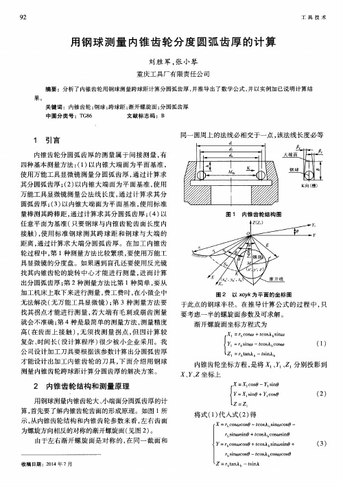
内锥 齿轮 分 圆弧 齿 厚 的测 量 属 于 间接 测 量 , 有 四种 基本 测量 方法 : ( 1 ) 以 内锥 大 端 面为 平 面基 准 ,
同一 圆周上 的法 ຫໍສະໝຸດ 必 相交 于一 点 , 该法 线 长度必 等
为螺旋 方 向相反 的对称 的渐开螺旋 面 ( 见图 2 ) 。 由于左右 渐 开螺 旋 面 是对 称 的 , 在 同一 截 面 和
Y = r b C O S O ) C O S O + t c o s A b s i n  ̄ s i n O +
r b s i n wc o s 0 一t c o s A b c o s t o c o s 0
使用 万 能工具 显微 镜 测 量分 圆弧 齿 厚 , 通 过计 算 求 其 分 圆弧齿厚 ; ( 2 ) 以 内锥 大端 面 为平 面 基 准 , 使 用 万 能工 具显微 镜测 量 公 法 线长 度 , 通 过 计 算 求其 分
圆弧齿 厚 ; ( 3 ) 以 内锥 大 端 面为 平 面基 准 , 使 用 标 准
:
F
一 [ E c o s {一 r k c o s ( + 6 ) ] 一
E E s i n ÷一 r k s i n ( 0 + 6 ) ] 一
/ l
f , _ o x 、
B = l O Z O X t l I _A = t s i n A b c o s A b C O S ( 0 + )
高( 在 齿 面上 接 触 ) , 无 须 找测 量 拐 点 , 但 因计 算 较
复杂 、 时 间长 ( 没计 算程 序 ) 很 少 被 小企 业 采 用 。我 公 司设 计加 工 刀具要 根据该 参数 计算 出分 圆弧齿 厚 才能设 计 出加工 内锥 齿 轮 的刀 具 , 下 面 介 绍用 钢 球
有控点共轭啮合运动几何测量法及其在锥齿轮精度测量中的应用
C nr l beP mt o j g t m slgK n mai-cler too y o tol l o - nu ae ehn ie t g o t cMe l a c - c n i r g
a d Is Ap l at n O lAc u a y M e s e n fBe e a s n t p i i I c o c r c a ur me to v lGe r
1 概 述
锥 齿 轮 ( 括 直齿 锥 齿 轮 、 齿 锥齿 轮 、 包 弧 准双 曲 面齿轮 等 ) 汽车驱 动 系统 中的重 要传 动元 件 , 制 是 其
析 , 照 锥齿轮 精 度标 准 对其 几 何 形 状 精度 及 使 用 按
性能进行 准确 评定。为实 现锥齿 轮 的“ 废 品制 零 造 ”需 要构 建锥齿 轮设 计一 加 工一 检测 闭环制 造 系 ,
硬度 高 、 面质 量好 。该 磨 削 装置 的 研制 成 功 为尼 表
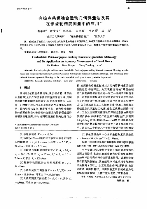
() 轮轴 与蜗 杆 轴 的初 始 中心 距 A 3砂 =( d+ d 一2 f / , 中 d h’ 2 其 ) =6r ,h = h 32= 7m, f 一1
X e Hu k n i a u D a o t n u n R r a Z a gZ o o g e t g h n  ̄ ln o
Ab 虹 s州 :" ̄ ai r c l a d f tr s0 o t l b e P ltc l f e b sc p n i e n e u e fC n r l l on - i p a oa g me II i rs c g mt  ̄ Mer  ̄ a s ig K  ̄ a d -  ̄ l1 r i t do y蛳 -
维普资讯
2O 第 3 O2年 6卷
螺旋锥齿轮齿面测量点分布新方法分析

螺旋锥齿轮齿面测量点分布新方法分析发布时间:2022-05-25T03:17:01.478Z 来源:《中国科技信息》2022年第2月第3期作者:王守信赵忠阳王雪微[导读] 针对现存螺旋锥齿轮齿面测试方法无法整体反映齿面结构性质和检测信息量太多、王守信赵忠阳王雪微中国航发哈尔滨东安发动机有限公司,黑龙江哈尔滨 150066摘要:针对现存螺旋锥齿轮齿面测试方法无法整体反映齿面结构性质和检测信息量太多、检测仪器成本高、检测路径繁琐、检测点分布未兼顾加工质量特点的影响等情况,介绍了螺旋锥齿轮齿面检测点的自适应布局方法,创建了螺旋锥齿轮齿面几何特点与加工质量特点的云模型,分析了螺旋锥齿轮齿面测试点布局算法,且以螺旋锥齿轮内部小齿轮为主展开了算法检验。
结果显示:采取该方法获取的螺旋锥齿轮齿面测试点布局体现了齿面几何特点与加工质量特点,布局测试点相对偏少,基本满足检测点布局预期。
关键词:螺旋锥齿轮;云理论;云模型;加工质量特点;螺旋锥齿轮体现了当前最繁琐的传动模式与高繁琐度的曲面生产类型,因为其重合度大、传动稳定、噪音低、承载性能高、传动比大、节约空间等优势,已经在工程机械、航天以及汽车等方面得到普遍使用。
信息化加工背景下,深入探究螺旋锥齿轮齿面测试办法,能够明显提升齿面生产精度,削减机床生产数值的调正反调。
齿轮齿面属于一个繁琐的空间型面,其检测点的分布计划直接影响着检测的真实性、客观性与检测效率及成本。
现如今,国内外广泛采取点阵式检测方法,按照创建的理论齿面系统,于齿面旋转投影面设计检测网格,获得网格节点坐标与该节点法向矢量,按照理论的齿面坐标数据管控三坐标检测机展开测量,进而获得齿面误差。
按照Gieason企业的要求,齿面测点布局一般采取顺齿方向选择九个测点,顺齿高方向选择五个测点,全齿面总共选择45个网格节点。
于齿面网格点建立曲面时,齿面表面的网格点越集中,拟合得到的齿面越可以体现真实齿面,为了让拟合后的齿面和真实齿面更为接近,有人选择在尺长方位取21个测点,于齿高方位选择13个测点。
三坐标测量机测量弧齿锥齿轮的方法与实例
一
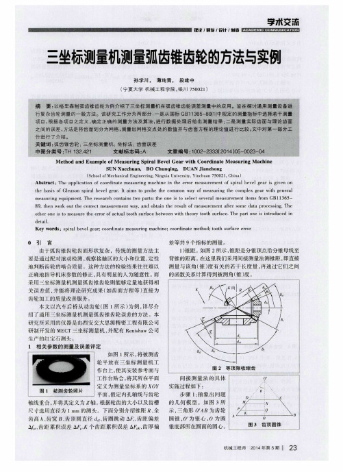
换 一个 齿 再做 相 同 的测量 ,得 出两 点 的坐 标 分 别为
( 1 1 8 . 7 9 7 5 , 2 1 3 . 5 3 7 9 , 一 9 7 . 0 3 02 ) , ( 1 l 9 . 3 1 5 l , 2 1 5 . 6 2 6 9 ,
到 的 结 果 , 误 差 为 △ _
l 0 O % 圭0 . 5 4 %。
× 1 0 0 % = 甏 妄
×
同在 中心 线 O 0 上, 故 N、 Q两 点 坐标 值 的横 、 纵 坐 标与 O 点相同, 而 z轴 方 向上 的 坐标 分 别与 M、 P在 Z轴方 向上
3 ) 齿 宽 。齿 宽 是 指锥 齿 轮 的轮 齿 沿 分锥 母 线量 度 的宽度 , 即 图 2中的 B 。图 5 所 示为 锥齿 轮 的轮齿 轴 截 面
测 量机沿 A 曰所在 的 圆周测 点 , 系统 经处 理 后得 冉 圆的特 征值 。 为减 小随机误 差 , 多测几 组数据 并求 平均值 , 得 出0
1 0 7 . 4 0 5 3 ) , 同理 可得 A ' B ' -1 0 . 5 8 3 3 。 比较 两次 测量 所得
步骤 3 : 得 到点 M、 P所在 圆周 的圆心 的坐 标 。 如图 3 ,
N、 Q分 别 为 M、 P各 自所 在 圆 周 的 圆心 。 南于 N、 Q与 O
、
齿距 累积误 差 △ 、 K个 齿 距 累积 误 差 △ x 、 齿 厚 偏
机械工程师 2 0 1 4 年第5 期 2 3
字木 交 流
理论 , 研发 , 设计 , 制 造
锥齿轮圆跳动量测量支架的设计

图1 盘形从动锥齿轮加工工序的设置图2 盘形从动锥齿轮精车削加工的尺寸控制示意2019年 第冷加工快,势必会影响技术系统的测量精度,遂选择48号工程参数,即“测量精度”为恶化的参数。
(2)查冲突矩阵取得发明原理。
根据得到的2个工程参数——改善参数44(生产率)和恶化参数48(测量精度),查2003版冲图3 TRIZ 的技术冲突“参数桥”图4 专用测量支架结构1、12.定位套 2.支架本体 3.蝶形螺母M12 4.标准型弹簧垫圈φ14mm 5.C 级平垫圈φ12mm 6.测量杆 7.紧固杆 8.定位支撑套 9.支撑杆 10.指示表安装孔 11.内六角圆柱头螺钉M4×10mm 13.热前盘形从动锥齿轮的内孔期冷加工)调整测量支架的测量杆和紧固杆,按上述方法在被测齿轮顶锥面的4个不同直径处测量、B 、C 和D ),取不同直径上所测跳动量的最大值,作为精车削后齿轮的圆跳动误差。
)根据零件图样给定的跳动公差值,判定零件是否合格。
图5 专用测量支架的零件6. 结语依据T R I Z 理论中技术冲突“参数桥”,优化锥齿轮圆跳动量检测系统的设计。
通过使用这套测量支架,盘形从动锥齿轮上顶锥相对于基准A 和基准B 的圆跳动量被实时抽检,后续弧齿的铣削质量得以有效保证。
通过调节测量杆和紧固杆以及更换不同尺寸的定位套,可用于其他规格盘形从动锥齿轮的圆跳动量检测。
参考文献:[1] 刘胜勇.一种锥齿轮具设计[J].汽车工艺与材料,2016,326(2):70-72.(收稿日期:20190213)新型夹紧机构的优点及效益:①可以装夹厚度大于活动块高度的所有板料。
②因为活动钳口斜向夹紧,所以能够保证工件地面与工作台紧密贴合。
③对工件被夹紧平面垂直度和平面度要求不高。
④工件上平面可以一次加工成型,节省二次或多次装夹时间。
⑤可以节省大量的压紧螺杆及压板。
3.结语该夹紧机构于2011年被授予实用新型专利,希望该专利能够通过该篇论文得到更好的推广与应用。
外文翻译--锥齿轮测量技术的最新进展
中文3900字Bevel gear of the latest developments in measurement technology1 OverviewBevel gear drive mechanism in the car, helicopter, machine tools and electric tools manufacturing industry, has been widely used. The use of different performance of the bevel gears are also different quality requirements, can be summarized including: ① a good contact area, can be a reliable torque transmission power; ② good match geometry, a smooth transfer of the movement, in order to ensure uniform load , transmission smooth, vibration small, noise low. Factories are usually small devices and dual-spot detection of rolling contact tester to control the quality of bevel gear, but in reality it is very difficult to determine accurately the performance of the bevel gear.Bevel gear and the precision of measurement of cylindrical gears similar, can generally be classified into three types: ①Coordinate Geometry Analysis of measurement type. That is, the bevel gear as a geometric entity, its geometric elements, respectively, the geometric precision of individual measurements; Gear Measuring Center is the main measuring instruments. ② Comprehensive engagement measurement accuracy. That is, the bevel gear transmission as a component, the accuracy of their transmission, contact spots, a comprehensive measurement of the vibration noise. The measuring instruments are mainly one-sided meshing bevel gear tester, bevel gear meshing two-sided bevel gear measuring and inspection machine rolling. Bevel Gear ③ the overall measurement error. It will bevel gear transmission as a function for the realization of the geometric entities, or by coordinate measuring method in accordance with the geometric precision of a single measurement to measure the overall error of bevel gears, bevel gears to achieve a single transmission error and the geometric precision of the intrinsic link between the quality of the analysis; or by mating single measurement, the use of mesh point scan measurement of bevel gears for the overall error of measurement, has been integrated bevel gear movement accuracy, contact spots, as well as the geometric precision of the individual. Therefore, the overall error of measurement of bevel gear is a measurement of the first two methods of integration and development.With the coordinate measuring technology, computer control and measurement technology, in recent years, the overall error of measurement of bevel gear technologyresearch development soon. Gear Measuring Center as a result of multi-cylinder coordinates, such as multi-function measurement instrument performance, data-processing capacity, bevel gear-type coordinates of analytic geometry measurement technology, has been the development of a single geometric error of measurement to the overall error of measurement of bevel gear, improved cone gear design, processing, quality testing to determine the accuracy and the use of the forecast performance of the bevel gear, such as the level of manufacturing technology. By China's own development, based on the "control point movement - geometric measurement principle" on one side of the bevel gear meshing point scanning technology and technology development based on the overall error of the bevel gear measuring instrument, it is more towards the production of the first line, so that China Bevel Gear measurement theory, the practical application of measurement technology has been further improved and developed.2.the main bevel gear precision measurement method and apparatus 2.1 Coordinate-style geometric measurement and analysis equipment Machinery Exhibition into a straight bevel gear-type coordinate measuring instrument there earlier products to represented KP42-type, but the complex structure of high accuracy. Since 1990, both before and after, CNC Gear Measuring Center to the market, coordinates arc bevel gear-type geometry of measurement error is the rapid development and popularization and application. Today's market, Gear Measuring Center from abroad, whether it is Klingberg Germany's P63, or the United States Gleason / mar the GMX275, M & M's Sigma 3, have been measured with the function of bevel gear. These instruments have reached VDI / VDE level provided a space measuring uncertainty for more than 2 microns; bevel gear on the geometric error of a single test, such as pitch deviation (including single pitch deviation, the cumulative pitch deviation , total cumulative pitch deviation), tooth profile deviations (including a total deviation of tooth profile, the shape of tooth profile error, tooth profile tilt deviation) and teeth to the error (including the teeth to the total deviation, deviation of the shape of teeth to the teeth to tilt deviation) and output deviation of three-dimensional shape of tooth surface morphology map.2.2 Integrated single-sided mesh rolling test measurement method and apparatusSingle-sided bevel gear meshing scroll detection methods have been used in production for many years. N0.513 Gleason in the United States rolling test machineas an example, in the measured single-sided bevel gear pair meshing, the simulation of its work, and to a certain degree of speed and load, adjust the V / H, for colored contact area (spot ) testing to determine the bevel gear pair under test contact conditions; through the use of acceleration sensors, pickup of vibration and noise measured on the tooth scan frequency harmonic detection. This method is "quasi-dynamic" measurement method, which bevel gear for the accuracy of detection is far from complete or accurate enough. Optical encoder used as the base point of view, to cut bevel gears for the accuracy of detection of the integrated single-sided meshing bevel gear tester, such as Germany's Klingberg PSKE900, because a single test items, in particular, it is difficult for the basis of test results Bevel Gear Machine parameters adjusted to give guidance, to improve processing quality bevel gears. Less cost-effective and therefore not much used in production.Gleason has introduced in recent years, the Phoenix 500HCT CNC bevel gear inspection machine is rolling with a rolling test at the same time and one-sided mating tester measurement function, measurement of both the tangential bevel gear integrated error, while the number of measuring cone gear contact area, three-dimensional structure of the noise analysis. The advanced models, such products represent the contemporary level of development, although expensive, but there are individual users at home. Klingberg also similar GKC60, such as Orion Hole T50 CNC bevel gear inspection machine.2.3Measurement error overall and equipmentThe overall error of measurement of bevel gear is rotating in the same angle displacement coordinates of the order will be based on the meshing bevel gear tooth surface of the work of the detection point measured by the geometric error of all the individual integrated into a bevel gear overall error map, and on this basis, bevel gears for the completion of a single geometric precision, and accuracy of an integrated campaign bevel gear analysis of contact state deputy measurement, the use of bevel gears to achieve the performance and quality assessment and monitoring. Bevel gear and the overall error of measurement apparatus, the current can be divided into three second-class. A class of analytic geometry for coordinate measurement type, the method is divided into "point-to-point measurement" and "point of scan measurements," equipment used in two ways for CNC Gear Measuring Center, but the allocation package by the measurement different; the other for the mating-type movement measurement geometry (ie, mesh-type scan measurement point, themethod for our first), the apparatus used for single-sided meshing bevel gear tester, equipped with a dedicated measurement bevel gear and measurement software package.(1) coordinate the overall bevel gear-type point-to-point measurement errorGear Measurement Center in, along with three-dimensional measurement of bevel gear tooth profile and tooth to the two directions, according to a pre-determined interval, the detection of the measured points of the tooth surface (usually the 5 tooth profile, tooth up 9 a total of 45 points) for the geometry error of measurement of 1.1 points. This method can be avoided and the measured three-dimensional probe in the measurement of tooth surface when the impact of friction and the measurement results. The measurement method is based on "direct measurement" principle, concrete steps are: first bevel gear in accordance with the adjustment of machine parameters and tool geometry parameters to be processed by calculating the large and small bevel gear tooth surface ideal geometric processing parameters; the tooth tooth surface as a reference, respectively, and the actual process (or after heat treatment) of large and small gear tooth surface compared to the actual measured tooth surface of the tooth surface with an ideal geometric deviation. MATCH procedures through the use of dedicated, determined corresponding to the actual measured tooth surface machining parameters of the illusion; re-engagement model in accordance with TCA analysis, calculated by the bevel gear pair integrated deviation and tangential contact conditions, test whether or not to meet the requirements. If necessary, the corresponding software will be based on the measurement results, re-calculate and adjust the machining parameters in order to re-try all they can be processed into a more satisfied with the quality of products.(2) coordinates of point scanning type bevel gear of the overall measurement errorSeiki, Osaka, Japan recently proposed using two-dimensional measurement of bevel gear tooth surface measurement to point scanning method has been satisfactory and reliable results. This method has the following characteristics: the workpiece by controlling the rotation, the parallel displacement of probe movement, to avoid the probe and the tooth surface friction between the adverse effects of measurement; measurement as a result of the use of scanning, surveying the region to cover the entire tooth surface, including Top Gear, as well as close to large and small end of theregion; measurement path can have a wide range of choices, usually tooth number and tooth number of each to the three, a total of six; each sample the number of scanning lines of up to 113 points, as sampling density, to reflect minor tooth surface waviness (which often is not pleasant ripple of the main sources of noise, the conventional point-to-point measurement method difficult to measure). The method used the "conjugation of" principle, the concrete steps are: First of all, the basis of machining parameters and tool parameters to be the ideal gear tooth surface geometry processing parameters, to calculate the conjugate with it, no transmission error of the virtual conjugate of the pinion tooth surface geometry parameters; the actual processing of the large gear tooth surface with the ideal gear tooth surface processing compare measurements to detect gear tooth profile and the relative deviation upward; the actual processing of the pinion tooth surface and calculation of be conjugate Virtual pinion tooth surface compared with measurements, to detect the gear tooth profile and the relative deviation upward. According to the relative deviation of measured, calculated by the deputy of the three-dimensional bevel gear tooth surface morphology of the comprehensive plan deviation, deviation and tangential contact with the integrated form of (including access to the path of contact area shape, size, location, etc.). By physical measurement, than on the authentication, point-to-point and point measurements of the measurement scan measurement results are consistent.(3) mating-type bevel gear to scan the whole point of the measurement errorChengdu Tool Research Institute of the bevel gear to mesh-type scan measurement point is one-sided meshing bevel gear tester, the design of the installation location by using a special measuring bevel gear and bevel gear test for measuring the rolling one-sided engagement. This measurement of bevel gear pair "basis" cone measured geometric parameters and the geometric parameters of gear pair are all the same. Measurement methods or the use of corrosion-paste method, in large and small measurement of the gear teeth and white make the necessary gear tooth profile or ridge to the measurement, by measuring the bevel gear or the gear tooth profile and match to the measurement of ridge bevel gear of the measured tooth contact transmission, the meshing of bevel gears to complete scanning the overall error of measurement points. Measurement path and measuring the number of gear teeth, and a total of 3 +3 is generally 6. Mating-type bevel gear to scan the overall error of measurement points used the "relative measurement of the local benchmark" principle.Measurement of specific steps are as follows: In accordance with the actual bevel gear pair sports / test experiment (or experience), elected by the factory can best meet the needs of the bevel gear use requirements vice as a "benchmark" bevel gear pair (known as the local benchmark), its integrated bias-cut to a cut tooth to the integrated form of bias and the contact area was identified as the assessment of the accuracy of the bevel gear of the main reference Vice indicators. Measurement of Bevel Gear and the local base of meshing bevel gears, bevel gears in mesh single tester measured tooth profile deviation of a consolidated Board - measured (local base bevel gear Deputy - Vice-bevel gear benchmarks, the same below), integrated to the deviation of tooth Board - measuring, cutting to the integrated deviation of the Board - measuring a tooth integrated deviation Board - measuring, shape Council contact area - measured, as well as the integrated deviation of three-dimensional tooth surface morphology of Fig Bureau - measuring and so on, and was recognized as a bulk evaluation of bevel gear testing The accuracy of a single bevel gear indicators mainly refer to baseline data. Measured part bevel gear and bevel gear measuring method according to the same measurement, the deviation of the workpiece has been Bevel Gear - Bevel Gear measurement data; by the computation of the corresponding deviations workers - Bureau data (that is, relative to the workpiece bevel gear partial cone base Gear indicator of the corresponding deviations of the accuracy). And then measured in accordance with the Public Works - Bureau deviation of the accuracy of data and indicators for the development of tolerance, to determine the bevel gear of the level of quality and interchangeability.Bevel gear overall error measurement method is simple, fast and reliable measurement information-rich, especially for mass production. As a result of measurement must be measured using special gear, so this method should not be used for a single measurement of small quantities. However, since the bevel gear at the same time the overall error of measurement also has a rolling bevel gear tester, so it can be used for single-piece and small-batch precision bevel gear Deputy comprehensive detection and production of the test workpiece and cutting tool debugging.3 ConclusionThrough the bevel gears in recent years the field of measuring the status of technology research and development, both at home and abroad to highlight the overall error of measurement of bevel gear technology, methods and development ofthe corresponding equipment. China's self-developed scanning mating-type bevel gear at the overall error of measurement technology, has been gradually recognized by domestic and foreign counterparts; technology development based on the overall error of the bevel gear measuring instrument is to the production line and continue to improve measurement practice . It is believed that the mesh-style points based on scanning the overall error of measurement of bevel gear technology, the establishment of precision bevel gear bulk products database, it is very possible to adopt in accordance with the use of computer-assisted measurement technique to achieve automatic arc bevel gear pair quickly.锥齿轮测量技术的最新进展1 概述锥齿轮传动机构在汽车、直升飞机、机床及电动工具制造业中,得到了广泛的应用。
弧齿锥齿轮的传动误差检测方法研究
弧齿锥齿轮的传动误差检测方法研究(一)立项依据与研究内容(4000-8000字):1. 项目的立项依据(研究意义、国内外研究现状及发展动态分析,需结合科学研究发展趋势来论述科学意义;或结合国民经济和社会发展中迫切需要解决的关键科技问题来论述其应用前景。
附主要参考文献目录)1.1 项目的研究意义弧齿锥齿轮因其平稳可靠的传动,较高的承载能力等优点被广泛应用于航空航天、航海、汽车、拖拉机、机床等工业部门中。
特别是航空传动系统中,弧齿锥齿轮是直升飞机的主减速器的关键部件,其啮合质量、寿命及可靠性是影响飞行器安全性能的重要因素。
但由于弧齿锥齿轮齿面几何拓扑结构复杂,设计、加工比较困难,在航空领域的应用中又存在诸如高速、重载、齿轮及其支撑因采用轻质结构而造成的变形问题等不利因素,对其啮合质量控制的研究非常困难,其动态性能与可靠性等问题始终难以得到全面解决,其动态设计问题也是工程设计中的难点。
衡量弧齿锥齿轮副啮合质量的重要指标是传动误差和接触印痕。
传动误差是齿轮振动的激励之源,已为前人的大量成果所证实。
弧齿锥齿轮作为一种局部点接触的不完全共轭的齿轮副,必然存在传动误差,它包括了动态性能和强度性能等大量信息。
但目前在设计或制造中都对传动误差缺乏必要的考虑和实用的方法,尤其在测试和检验环节方面,完全没有相应的方法、设备和手段,更是缺乏对传动误差的明确指标要求,使得对其动态性能的改进无从着手。
传统的设计方法是基于印痕控制的方法,加工设计、切齿、检测,到不断反复修正,实际上是以印痕为控制目标的逼近过程,在这一过程中,齿面印痕是最终的目标和要求。
当前我国弧齿锥齿轮的设计和生产,均采用这一方法。
齿轮的动态性能主要决定于齿轮副的传动误差。
传动误差与齿面印痕既有着深刻的内在联系,又各自反映着齿轮性能的不同方面。
齿轮接触传动对于载荷具有非线性的力学特性,尤其是点接触的弧齿锥齿轮传动的非线性更为突出。
片面重视齿面印痕而忽视传动误差,是由于当时齿轮转速不高,强度是主要矛盾,振动问题还不十分突出。
弧齿锥齿轮测量齿面的NURBS重构
谷霁 红 , 建华 , 红卫 , 李 樊 刘光 磊
( 北 工业 大学机 电 学院 , 西 西安 70 7 ) 西 陕 1 0 2
NURBS Re t u to ft e s r d To t r a eo ia v lGe r s r c i n o he M a u e o h Su f c fSp r lBe e a s
面的 曲线度 , 而 可 以创 建 出更 逼 真 的 造 型 。近年 从 来 , 军[ 等 人研 究 了螺旋 锥 齿轮 的齿 面三 坐标 测 王 2 ] 量 方 法 ; 智 剑[ 等人 研 究 了交错 轴准 双 啦 面齿 苏 3
轮 测量 齿面 的 NUR S重 构及 其光顺 处理 。本 文则 B
就 是 D P主要 应 用 领 域 之 一 。特 别 是 随着 控 制 理 S 论 的发 展和 高性能 控 制 器 的 需 求 , 般 的单 片机 或 一 多片微 处理 器都 不 能满 足 复 杂 而 先进 的控 制 算 法 , 使 得 D P成 为 这种 应 用 场 合 的首 选 器 件 L 。通 过 S 4 ] D P在 车载 转 台控 制 系统 的应 用 , 整 个 系统 开 发 S 使
中 图分 类 号 : THl 2 4 3 .
文献标 识码 : A
文 章 编 号 :0 1 2 7 2 1 ) 2 0 1 3 10 —2 5 (0 0 0 —0 4 —0
Ab ta t T h hr e c r i t s’vaue n t s r c : e t e oo d na e l s o he
bi u c N U R BS(n n ~ u f r c bi o nio m r ton l — s lne a i a B pi
锥齿轮公差标准_DIN3965.
锥齿轮公差 DIN3965UDC 621.833.2:621.753.1 德国标准 1986年8月取代1981年9月版为了与国际标准化组织(ISO)发行的标准的现行实践相一致,整个标准都使用逗号作为十进制标志。
目录第一部分基本内容 (2)1. 应用范围 (2)2. 前言 (2)3. 符号和量 (2)4. 齿坯尺寸公差 (3)5. 齿轮公差体系结构 (4)5.1公差间的关系 (4)5.2参数的误差和偏差 (4)5.3锥齿轮公差等级 (5)5.4公差的计算 (5)6. 应用公差 (6)7. 附加的测量方法 (6)7.1径向跳动 (6)7.2节距误差 (7)7.3切向综合误差 (7)8. 齿面接触斑点 (7)第2部分单个参数公差 (9)1. 前言和应用范围 (9)2. 公差 (9)第3部分切向综合误差公差 (25)1. 前言和应用范围 (25)2. 公差 (25)第4部分轴交角误差和轴交点偏差公差 (41)1. 前言和应用范围 (41)2. 公差 (41)第一部分基本内容1. 应用范围此标准为直齿,曲齿及带偏置距或不带偏置距的弧齿锥齿轮指定公差,相应的模数范围为1mm到50mm,最大节圆直径达2500mm。
2. 前言为确保标准满足锥齿轮所有功能要求,涉及到运转平稳性,承载能力,均匀的角度传递和统一的使用寿命,齿轮系统某些参数的误差有必要控制在给定的范围内。
公差大小已使用与圆孔配合相类似的原则确定了。
因此,与圆孔配合类似,目前技术无法实现的精度对应的公差等级也已被确定,因为它们代表将来有可能达到的精度。
3. 符号和量a 齿面接触斑点尺寸,轴向偏移c 齿面接触斑点尺寸d 节圆直径;齿面接触斑点尺寸d m中点节圆直径d B测试凸缘直径d R分度曲面直径e 齿面接触斑点尺寸f 个体误差;齿面接触斑点尺寸f a轴线交点误差f i’齿间切向综合误差f k’切向综合误差的短波成分f l’切向综合误差的长波成分f p相邻周节误差f u相邻周节偏差fΣ轴交角误差m 模数m mn 中点锥距处的法向模数t B安装距(顶点到背部的距离)t E轮冠距(大端齿顶圆所在平面至定位面的距离)t H辅助面距(辅助平面到定位面间距离)u 传动比B 孔径F 综合累积误差F i旋转偏差F i’切向综合误差F p节距累积误差F r径向跳动F rd 测试凸缘直径dB 相对于大轮轴线的径向跳动 F rs 参考平面F1相对于大轮轴线的径向跳动 F 1,F 2 参考平面 K 1-K 9辅助量 R m 中点锥距 δ 分锥角 δa 顶锥角 εα 端面重合度 εβ 纵向重合度 εγ 总重合度 φ 公差增量 Σ 轴交角图1 齿坯和安装距公差(同样可以参考DIN3971中的定义)4. 齿坯尺寸公差(适用于切齿之前的齿坯)计量、制造和装配所必须的测试平面和测试直径的公差也同样要满足。
- 1、下载文档前请自行甄别文档内容的完整性,平台不提供额外的编辑、内容补充、找答案等附加服务。
- 2、"仅部分预览"的文档,不可在线预览部分如存在完整性等问题,可反馈申请退款(可完整预览的文档不适用该条件!)。
- 3、如文档侵犯您的权益,请联系客服反馈,我们会尽快为您处理(人工客服工作时间:9:00-18:30)。
均规定了适用范围。 • DIN 3965-1986,适用于齿面中点法向模数mn≥1mm的各类锥齿轮。 AGMA 2009-B01 反映了齿轮检测新技术,如坐标测量方法。 AGMA 2009-B01及DIN 3965-1986规定的测量项目的公差值均表示为中点 法向模数及测量直径的计算公式,使用准确方便。 GB/T 11365-1989、GB/T 10225-1988规定的测量项目的公差值列为表格, 为一范围值。
Ri Rg k g 0.001 Li Rg k g 0.001
锥齿轮齿距误差测量
f pti i i 1; i 1, n f pt max(abs( f pti ,max ), abs( f pti ,min )); i 1, n Fp max( i ) min( i ); i 0, n
一、锥齿轮精度标准
发展情况:
1、部标JB180—60 2、锥齿轮整体误差理论的影响
3、GB11365—89没得到好好贯彻
一、锥齿轮精度标准
2. GB/T 11365-1989共计规定了23个测量项目:
切向综合误差 Fi ' ( Fi ' )
一齿切向综合误差 Fi ' ( Fi ' )
齿距累积误差 Fp ( Fp ) K个齿距累积误差 Fpk ( Fpk ) 齿圈跳动 Fr ( Fr ) 齿距偏差 f pt ( f pt ) 齿形相对误差 fc ( fc ) 齿厚偏差 Es ( Ess、Esi、Ts )
接触斑点 齿轮副侧隙 齿轮副侧隙变动量 Fvj ( Fvj ) 齿圈轴向位移 f AM ( f AM ) 齿轮副轴间距偏差 fa ( fa )
Z=39、m=11.131、F=62、 =34 22'、 797 '
,其齿距极限偏差公差
精度等级
AGMA 2009-B01
GB/T 11365
DIN 3965
6级 7级
12.16 17.2
16 22
16 22
二、锥齿轮测量
测量阶段 测量项目
1.刀夹辅具精度的测 量 2.首件的测量 3.机床精度的检定 1.按工艺要求进行工 序质量的测量 2.热处理变形测量 对完成全部加工工序 的锥齿轮进行最后测 量
锥轮整体误差测量仪 CSZ500(成都工具研究 所)
最大直径500 mm
可测出多种误差
锥齿轮的综合误差测量
2、双啮综合误差测量
锥齿轮轴交角变动测量仪 量仪名称 规 格 特 点
PKE140A、280A型锥齿 最大直径分别为85mm和 轮检验仪(德国制造) 270mm 140型锥齿轮轴交角检 验仪(美国制造) PZ375型齿轮检验机 (德国制造) 最大直径108mm刻度值 0.01 mm 模数1~10,最大直径 375mm,刻度值0.01mm 测量简便迅速
测量目的
控制工艺装备及机床 精度等因素引起的加 工误差 控制生产过程的稳定 性,防止废品和提供 改进质量的依据 评定齿轮的精度,确 定齿轮是否符合图样 要求
预防测量
工艺测量
最终测量
锥齿轮误差检验组
GB/T 11365-1989公差组及检验组: 分三个公差组。第Ⅰ公差组:主要影响 运动精度;第Ⅱ公差组:主要影响工作平稳性;第Ⅲ公差组:主要影响接触 质量。
锥齿轮三维形状测量 add来自 ded heel
toe
齿面缩减量:齿顶及齿根≤0.6mm 缺省值:齿面按(m+2)x(n+2)等分
齿面网格点测量路径规划
锥齿轮三维形状测量
三、锥齿轮测量仪器
1、滚动检查仪
2、整体误差测量仪
3、齿轮测量中心
4、坐标测量机
1、滚动检查仪(普遍型)
1、滚动检查仪(万能型)
" " (Fi ) 轴交角综合误差 Fi " " ( fi ) 一齿轴交角综合误差 fi ' ' ( f zk ) 周期误差 f zk
' ' 齿轮副切向综合误差 Fic ( Fic ) ' ' ( fic ) 齿轮副一齿切向综合误差 fic " " 齿轮副轴交角综合误差 Fic ( Fic ) " " 齿轮副一齿轴交角综合误差 fic ( fic ) ' ' ( f zkc ) 齿轮副周期误差 f zkc ' ' 齿轮副齿频周期误差 f zzc ( f zzc )
最新仪器
Gleason 600HTT、Oerikon T60:传动误差、接触斑点、振动、噪声
等。
格利森凤凰检查仪测量原理
2、整体误差测量仪
2、整体误差测量仪
2、整体误差测量仪
3、齿轮测量中心
测量与分析:
测量与分析:
测量结果的利用:
Thank
you
锥齿轮测量基础
北京工业大学
石照耀
2010.4.25
长沙
锥齿轮测量作用:
锥齿测量的实际现状:
1、远远不能满足实际生产的需要;
2、远远落后于圆柱齿轮测量技术
原因:几何形状复杂; 加工方法复杂; 误差理论研究不够深入; 测量原理复杂;
主要内容:
一、锥齿轮精度标准
二、锥齿轮测量
三、锥齿轮测量仪器
一、锥齿轮精度标准
锥齿轮的综合误差测量
2、双啮综合误差测量
锥齿轮轴交角变动测量仪 量仪名称 规 格 特 点
PKE140A、280A型锥齿 最大直径分别为85mm和 轮检验仪(德国制造) 270mm 140型锥齿轮轴交角检 验仪(美国制造) PZ375型齿轮检验机 (德国制造) 最大直径108mm刻度值 0.01 mm 模数1~10,最大直径 375mm,刻度值0.01mm 测量简便迅速
;
• •
时,园整到最近的整数; 10 m 时,园整到最近的 0.5 m ; 2 5 m 时;园整到最近的 0.1 m 。
一、锥齿轮精度标准
5. DIN 3965-1986 公差计算方法
一、锥齿轮精度标准
6. GB/T 11365-89规定的误差项目较多,一些项目的定义不准确,如:齿轮 副一齿轴交角综合误差(分锥顶点重合),一些项目不便于测量,如:齿 形相对误差。公差值较DIN 3965和ANSI/AGMA 2009-B01大。未反映关于 齿形误差的CMM测量新技术应用。 • 相对地,AGMA 2009-B01规定的公差比其他标准 规定的公差小。例如:当 锥齿轮参数为 分别为:
锥齿轮的单项目误差测量
1、齿距误差测量
2、齿圈跳动测量
3、齿 厚 测 量
4、侧隙和侧隙变动量测量
与圆柱齿轮测量类同
锥齿轮齿距误差测量
Rg Rg ( X p , X b , Em , m , i, j, Sq , Rcp , bp , Ra ;t , qt ) ng ng ( m , i, j, bp , Ra ;t , qt )
锥齿轮的综合误差测量
3、滚动检测
序 1 2 号 用 途 新产品调试 热处理以前的齿部检验
滚动检验机的应用 应用范围 分析和确定切齿机或研齿机的调整 数据 评定生产中的齿轮齿面接触区的特 性、侧隙和侧隙变动量等 1. 进行齿轮副的选配,以便获得最 佳运转质量和确定最佳安装距 2. 挑出毛刺
最终齿部检验 3
锥齿轮的综合误差测量
1、单啮综合误差测量
锥齿轮单面啮合综合测量仪
量仪名称 格利森NO552单啮检验 机(美国制造) PSKE900型、PEK300型 单啮仪(德国制造) 规 格 特 点 还可以测量各种齿轮的 齿距、径跳和齿距累积 等误差 PSKE900型也可以测量 圆柱齿轮
最大直径508 mm 最大直径425mm,偏置距 ±50 mm
• 齿轮副轴交角偏差 E ( E )
一、锥齿轮精度标准
3、ANSI/AGMA 2009-B01规定了测量项目、测量方法、数据处理方法、
公差计算方法等。
1) 单个齿轮测量: • 单齿周节及周节累积变化 • 跳动 • 齿厚 • 齿形:CMM(齿形误差拓 扑图) 2) 配对齿轮(通常经过研齿) • 首先按单个齿轮测量 • 接触区检测 • 侧隙 • 单面啮合综合检查
1. 锥齿轮精度标准: • • • GB/T 11365-1989,适用于齿面中点法向模数mn≥1mm的各类锥齿轮。 GB/T 10225-1988,适用于齿面中点法向模数mn<1mm的各类锥齿轮。 ANSI/AGMA 2009-B01(2001.10),总的来说适用于齿面中点法向模数 mn≥0.2mm、齿数≥5、测量直径≥5mm的各类锥齿轮,但对每一误差项目
3) 单个齿轮与参考标准齿轮配对检测 • 首先按单个齿轮测量 • 接触区检测 • (齿厚)侧隙 • 双面啮合综合检查 • 单面啮合综合检查:所有周节 4) CMM方法检测齿形误差
一、锥齿轮精度标准
4. ANSI/AGMA 2009-B01 公差计算方法
•
步长系数:两相邻两精度等级的步长为 园整:公差值 计算公式: