340300001900_说明书_V1.0_中文(ABB_LOGO)_20120221
ABB定位器选型表
或角行程执行机构 VDI/VDE 3845
外管为
塑料管
铜管
不锈钢管
用于一体安装至 23/24, 23/25 或 23/26 控制阀
内管
外管为
铜管
1)
不锈钢管
1)
1) 外管仅用于 23/24 和 23/25 控制阀(“气关/弹簧开”型,否则只需内管)
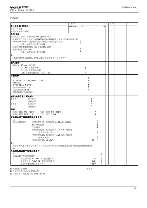
目录号
7959125 7959126
7959106 7959107 7959108 7959109
防爆保护 无
ATEX Ex I I 2 G EEx ia/ib I I C T6 FM/CSA ATEX EEx n A II T6 IECEx Ex ib IIC T6 IECEx Ex nA II T6 其他防爆证书按需提供
1
2
0 1 2 4 5 6
输出/安全位置(断电时)
单作用,
故障安全
1
故障闭锁
带 24 V DC/AC 微动开关
带接近开关
SJ2 - SN(常闭或逻辑 1)
SJ2 - S1N(常开或逻辑 0)
组件用于
备件 备件箱
数字位置反馈
带 24 V DC/AC 微动开关
带接近开关
SJ2 - SN(常闭或逻辑 1)
SJ2 - S1N(常开或逻辑 0)
I/P 模块(单作用,故障安全) I/P 模块(单作用,故障闭锁) I/P 模块(双作用,故障安全) I/P 模块(双作用,故障闭锁)
1) 仅适用于带机械式位置指示器的型号 2) 仅适用于防爆型 3) 仅用于环境温度 -25 °C to +85 °C
目录号
7959111 7959112 7959113 7959114
abbAM3000说明书

abbAM3000说明书1、概述AM3000系列PID智能调节仪与各类传感器、变送器配合,可实现对温度、压力、液位、成分等过程量的测量、变换、显示、通讯和控制。
采用先进的PID智能控制算法,抗超调,具备自整定(AT) 功能。
误差小于0.2%F-S, 并具备调校、数字滤波功能,可帮助减小传感器、变送器的误差,有效提高系统的测量、控制精度。
2、型号:AM-3000仪表基本功能:AM3000型为内给定(定值控制)控制器。
外形尺寸:横式160x 80x 125,开孔152x 76。
3、技术规格3.1 输入规格:电流: 4mA~20mA。
3.2调节方式:连续PID调节。
3.3输出规格: 4mA~20mA负载能力大于60092:报警输出: 继电器触点容量220V AC, 3A。
3.4电源规格电源: 220V AC供电的仪表: 85V~265V,功耗小于7VA。
3.5其它性能指标工作环境: 0C ~50C, 湿度低于90%R-H: 宽温范围的仪表需在订货时注明。
显示范围: -1999999, 小数点位置可设定。
显示分辨力: 1/10000。
基本误差:小于士0.2%FS。
测量分辨力: 160000,16位A/D转换器。
测量控制周期:最短0.2秒,可通过参数设定。
手自动输出:自动/手动双向无扰动切换。
电磁兼容: IEC61000-4-2 (静电放电),II级; IEC61000-4-4 (电快速瞬变脉冲群),IV级。
4、安装与接线:(1)为确保安全,接线必须在断电后进行。
(2)交流供电的仪表,其古端是电源滤波器的公共端,有高压,只能接大地,禁止与仪表其它端子接在一起。
abb变频器故障代码表
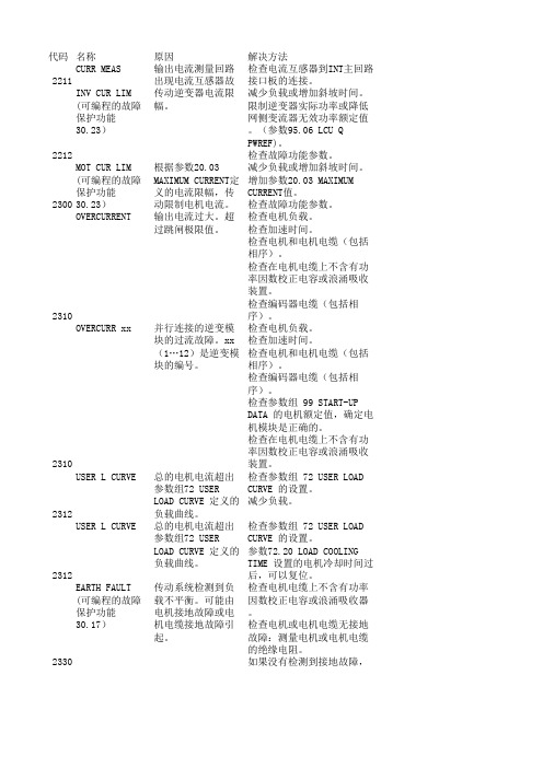
代码名称原因解决方法2211CURR MEAS输出电流测量回路出现电流互感器故检查电流互感器到INT主回路接口板的连接。
2212INV CUR LIM(可编程的故障保护功能30.23)传动逆变器电流限幅。
减少负载或增加斜坡时间。
限制逆变器实际功率或降低网侧变流器无效功率额定值。
(参数95.06 LCU QPWREF)。
检查故障功能参数。
2300MOT CUR LIM(可编程的故障保护功能30.23)根据参数20.03MAXIMUM CURRENT定义的电流限幅,传动限制电机电流。
减少负载或增加斜坡时间。
增加参数20.03 MAXIMUMCURRENT值。
检查故障功能参数。
2310OVERCURRENT输出电流过大。
超过跳闸极限值。
检查电机负载。
检查加速时间。
检查电机和电机电缆(包括相序)。
检查在电机电缆上不含有功率因数校正电容或浪涌吸收装置。
检查编码器电缆(包括相序)。
2310OVERCURR xx并行连接的逆变模块的过流故障。
xx(1…12)是逆变模块的编号。
检查电机负载。
检查加速时间。
检查电机和电机电缆(包括相序)。
检查编码器电缆(包括相序)。
检查参数组 99 START-UPDATA 的电机额定值,确定电机模块是正确的。
检查在电机电缆上不含有功率因数校正电容或浪涌吸收装置。
2312USER L CURVE总的电机电流超出参数组72 USERLOAD CURVE 定义的负载曲线。
检查参数组 72 USER LOADCURVE 的设置。
减少负载。
2312USER L CURVE总的电机电流超出参数组72 USERLOAD CURVE 定义的负载曲线。
检查参数组 72 USER LOADCURVE 的设置。
参数72.20 LOAD COOLINGTIME 设置的电机冷却时间过后,可以复位。
2330EARTH FAULT(可编程的故障保护功能30.17)传动系统检测到负载不平衡。
可能由电机接地故障或电机电缆接地故障引起。
ABB控制产品AF系列样本手册
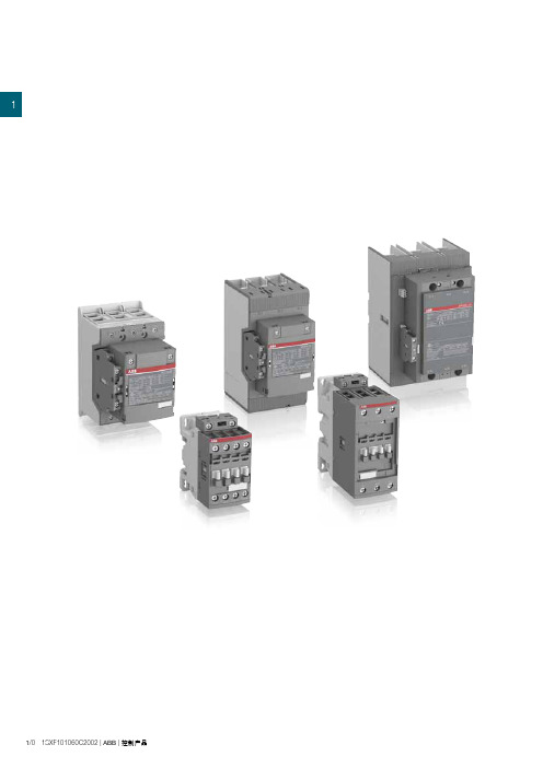
11/0 1SXF101060C2002 |ABB|控制产品1概览1/2订货信息4 - 45 kW / 5 - 60 hpAF09 ... AF38 交/直流操作1/5AF09Z ... AF38Z 交/直流操作,低功耗1/6AF40 ... AF96 交/直流操作1/7主要附件1/855 - 200 kW / 75 - 300 hpAF116 ... AF146 交/直流操作,带1NO + 1NC辅助触点1/10AF190 ... AF370 交/直流操作,带1NO + 1NC辅助触点1/11主要附件1/12 200 - 560 kW / 300 - 900 hpAF400 ... AF750 交/直流操作,带1NO + 1NC辅助触点1/14AF1250 ... AF2650 交/直流操作,带1NO + 1NC辅助触点1/15主要附件1/16技术数据1/18端子标识和位置1/31主要尺寸1/34ABB|控制产品| 1SXF101060C2002 1/11用于控制电动机及电力线路IEC (1)AC-3 额定功率θ ≤ 60 °C (2), 400 V kW4 5.57.5111518.518.522303745UL/CSA 3 相电动机480 V hp57.5101520203040506060交/直流控制电压型号AF09AF12AF16AF26AF30AF38AF40AF52AF65AF80AF96IEC AC-3 额定工作电流θ ≤ 60 °C (2), 400 V A912182632384053658096 AC-1 额定工作电流θ ≤ 40 °C, 690 V A25283045505070100105125130UL/CSA一般应用的额定电流600 V A252830455050608090105115 NEMA NEMA 尺寸000—1——2——3—(1) 1000 V IEC额定参数,适用于AF146 ... AF2650接触器。
ABB定位器型号说明

ABB定位器性能特点:ABB(TZID-C)智能阀门定位器的引进,为现场执行器的数字化通讯,全厂的一体化管理通过了先进的工具。
TZID/TZID-C突破传统的定位器概念。
采用TEIP11作为核心部件,结合微处理技术,内置通讯功能。
通过安装,适合转动型及直行程阀门的控制,定位精度高,行程范围大直行程:20~150mm,转动型:达125度。
气容≥13.5kg/小时,气耗≤0.03kg/小时,通过自动零点/量程的调整,简化调试。
采用传感器技术进行温度及位置补偿,具有抗振动能力高达10g,10~150Hz;温度范围-40~+85°C的卓越特点。
通过HART或Profibus/FF通讯接口,建立现场与控制室的实时联系,可进行参数调整,状态监控。
自由组态的输出特性,最大程度地改善球阀/碟阀的输出特性,可采用廉价的球阀/碟阀+智能阀门定位器同时达到关断阀与调节阀的特性。
ABB定位器V18345-1010121001 单作用、故障安全、带4~20mA反馈两线制、连接1/2-14NPTV18345-1010221001 单作用、故障闭锁(三断保护)、带4~20mA反馈两线制、连接1/2-14NPTV18345-1011121001 单作用、故障安全、带4~20mA反馈两线制,ib苯安防爆、连接1/2-14NPTV18345-1017121001 单作用、故障安全、带4~20mA反馈两线制、ia苯安防爆、连接1/2-14NPTV18345-1027120001 单作用、故障安全、无反馈,ia苯安防爆、带HART通信、连接1/2-14NPTV18345-1010520001 双作用、故障闭锁(三断保护)、无反馈、连接1/2-14NPTV18345-1010421001 双作用、故障安全、带4~20mA反馈两线制、连接1/2-14NPTV18345-1010521001 双作用、故障闭锁(三断保护)、带4~20mA反馈两线制、连接1/2-14NPTV18345-1027420001 双作用、故障安全、无反馈,ia苯安防爆、带HART通信、连接1/2-14NPT等。
ABB测量与分析数据册 - 扩展模块 - 概述XSeries、RMC和XIO说明书

—ABB MEASUREMENT & ANAL YTICS | DATA SHEET Expansion module - overviewXSeries, RMC, and XIO2 EXPANSION MODULE | XSERIES, RMC, AND XIO | DS/2101105-EN—OverviewHardware functionality of XSeries, RMC, and XIO devices can be extended in a flexible and simple way by adding modularI/O as needed. Totalflow’s TFIO modules are designed to accommodate low power, harsh environments at economical cost. The system recognizes the module types automatically and configures the I/O Scanner subsystem accordingly.The modules are interfaced to the engine card by an I2C bus. On top of this bus, Totalflow has implemented an efficient I/O protocol to exchange information between the modules and the engine card. The bus operates in a master/slave mode, with the engine card acting as master.The I/O module hardware is packaged in DIN mountable enclosures that employ Phoenix Contact technology forfield wiring (see back of this datasheet). The modules also interconnect with each other to provide the necessary power and interface signals along their bus. Installation consists of snapping the Phoenix connector onto the DIN rail and moving the module into position directly beside and snapped to the next module.Hot PluggableThe new TFIO module are hot-pluggable and can be inserted, replaced or removed during the normal operation of the device with no restart required. The system will detect the changesin the TFIO bus and reflect the state of the modules thatcan be verified on PCCU. User should take power precaution measurements when execution this action. All modules are designed to meet Class 1, Division 2, Groups C & D.All modules have 4 LED annunciator lights; a manual reset button and an address range from 0 through 7. On the faceplate of each module (see page 3 of this datasheet) you will see: • Type of module• LED light panel• Reset button switch• Module address selector —LED annunciatorsThe first light (RUN) is blinking when the engine card recognizes the module.The second light (ACTIVITY) toggles on or off with each communication from the engine card.The third and fourth lights (MODE) reflect one of two possible statuses of the module as shown on the bottom of the faceplate.—Reset buttonInside a small hole on the front of the module is the reset button switch. You should reset the module anytime you change the address of the module. This constitutes a warm start of the module’s internal program. To reset the module, use a fine point instrument, such as the end of a paper clip, inserted into the hole until the module resets.—Address selectorEach module of the same type must have a unique physical address, 0-7, selected prior to powering up the module. Different types of modules may share the same address. If you change the address of a module, you must do a reset.See next page for depiction of TFIO module package and summary of module types.EXPANSION MODULE | XSERIES, RMC, AND XIO | DS/2101105-EN—TFIO module specifications—XSeries, RMC, XIO specifications3—ABB Inc.Measurement & AnalyticsQuotes:************************.com Orders:**********************.com Training:*************************.com Support:***********************.com+1 800 442 3097 (opt. 2) Main Office7051 Industrial Boulevard Bartlesville, OK 74006Ph: +1 918 338 4888/upstream—We reserve the right to make technical changes or modify the contents of this document without prior notice. With regard to purchase orders, the agreed particulars shall prevail. ABB does not accept any responsibility whatsoever for potential errors or possible lack of information in this document.We reserve all rights in this document and in the subject matter and illustrations contained therein. Any reproduction, disclosure to third parties or utilization of its contents – in whole or in parts – is forbidden without prior written consent of ABB. © Copyright 2020 ABB. All rights reserved.D S /2101105-E N R e v . A H 03.2020。
ABB 低压数字设备技术规格说明书
© Copyright 2022 ABB. All rights reserved.Specifications subject to change without notice.1S D C 200083B 0201 - 2022.11—ABB S.p.A.5, Via Pescaria I-24123, BergamoPhone: +39 035 /lowvoltage—LOW VOLTAGETechnical specifications for low voltage digital unit1TECH N I C A L S PECI F I C ATI O N S FO R LOW VO LTAG E D I G ITA L U N IT— The goal of this specification is to define the basic design requirements of digital unit for low voltage installations with rated voltage up to 1150V ACand rated current up to 6300A.It shall enable easy update installations, providing monitoring, protection and control functions.The current document describesthe general aspects of the unit,such as conformity with Standards, functional, environmental and construction characteristics and alist of the accessories available.2—General Characteristics-Conformity with StandardsDigital unit used in low voltage installations shall be constructed and tested in accordance with international IEC 60255 and UL 508 series of Standards:• IEC 60255-26 (ECM requirement), IEC 61000-6-2 (EMC-Immunity Standard) and IEC 61000-6-4 (emission standard)• IEC 61010-1 (General requirement)• UL 508 (Standard for Industrial Control Equipment)• UL C37.90 and C37.90.1 (using shielded cables)• CEI 0-16• DNV-GL (type approval certificate)• RINA (type approval certificate).In addition it shall respect the following directives:• CE "Low Voltage Directives" (LVD) 2014/35/EU• CE "Electromagnetic Compatibility Directive" (EMC) 2014/30/EU• UL and cULus.3TECH N I C A L S PECI F I C ATI O N S FO R LOW VO LTAG E D I G ITA L U N IT—Environmental characteristicsTemperature:• Operating temperature for unit and accessories: -25 °C ...+70 °C• Storage temperature: -40°C …. +70°CEnvironmental parameters:Unit shall be able to operate in particularly difficult industrial atmospheres.It shall have been tested in accordance with:• IEC 60068-2-1: dry cold climate• IEC 60068-2-2: dry hot climate• IEC 60068-2-30: humid hot climateProtection degree:shall be not less than IP40Vibrations:Unit shall comply with the following mechanical compatibility standards and classes.• IEC 60255-21 class 1 (vibrations, shocks and blows), with DIN guide assembly • IEC 60255-21 class 2 (vibrations, shocks and blows), with door assembly.• Rated current shall be between 100 and 6300 A with the possibility of set trip threshold of L protection from 40A;• Digital unit shall be suitable for installation with rated frequency 50 Hz or 60 Hz.• Two different versions of digital unit shall be available, according to monitor and protection functions required. It shall be possible to up-grade unit with advanced software functions directly from the online ABB Ability Market-place TM .• Digital unit shall provide supervision functions to monitor main energy parameters and power quality, either locally or on cloud energy moni-toring system, without requiring external unit for communication or gateway.—Functional characteristicsIt shall be possible to connect directly the digital unit in network with phase to phase voltage up to 690V. It shall be possible to connect digital unit with external transformers to enable installation of device in network with rated service voltage up to 1150 V AC.• Datalogger shall ensure information on trigger events for fast diagnosis in case of fault or anomalies.• Digital unit shall be suitable for protection based on current and voltage measurement.• Digital unit shall be provided with specific pro-tection for generators and motors.• Digital unit shall be provided with algorithm to enable optimization of energy consumption of plant and with communication to enable De-mand response functions.• Self-diagnosis functions shall be always available to check continuity of internal connection of unit and with sensors, pre-alarm and alarm for abnor-mal temperature, to guaranty correct operation.4• Digital unit shall be designed to be door or DIN-rail mounted.• Digital unit shall be designed with orientable digital contacts to enable mounting on DIN rail or on the front door of the switchboard.• Labels for wiring connection shall be visible in each mounting solution allowed.• Unit shall be provided with software for commis-sioning, analysis of fault and testing of commu-nication bus.• Terminals for current sensors shall be provided either for 3 poles and 4 poles installations.• Rogowski coil current sensors shall be provided to enable flexibility, linearity and easy detection of quickly current variations as well as harmonic contents.—Construction characteristics• Closed current sensor with copper terminals for busbar up to 6300A shall be available to allow in-stallation in switchboards with reduced space.• Closed current sensors shall be available in ver-sion without copper terminals for cable connec-tions for current up to 1600A.• Opening Rogowski coils up to 6300A, not requir-ing auxiliary power supply, shall be provided also for upgrade of existing switchgears. • Terminal box shall be with spring clamps.• It shall be possible to install the electrical acces-sories without removing the cover.• Dedicated slot for power supply module.• Device unique serial number shall be visible on sticker, available on the touchscreen menu and also remotely readable via data communication.• Warranty shall be available for 1 year with exten-sion up to 5 years.5TECH N I C A L S PECI F I C ATI O N S FO R LOW VO LTAG E D I G ITA L U N IT—AccessoriesThe following accessories shall be available for the whole range:• Digital unit shall be provided with plug-in on board power supply unit.• Remote control and signaling shall be possible through digital I/O freely configurable. It shall be possible to add additional I/O modules for 2, 4 or 10 more digital I/O. it shall be possible to con-nect at the same time up to three external digital I/O module for 11 input and 10 output with one unit by local bus.• It shall be possible to connect 3 or 6 temperature inputs and 1 or 2 analogic 4-20mA inputs.• It shall be possible to adjust the rated current of digital unit by applying at the front part suitable plug.• It shall be possible to upgrade basic measuring functions, enabling measurement of phase and neutral voltages, powers and energy, through ad-ditional plug-in measuring module.When required following accessories shall be available:• Unit shall be supplied homopolar toroid for earth conductor (star center of the transformer), with rated current from 100 to 800 A.• Relay shall be supplied with homopolar toroid for residual current protection to enable monitoring of earth current from 3…30 A.• Unit shall be supplied with accessory to mea-sures voltages from two phases of one line through an external transformer for check of synchronization of parallel lines. Module shall be provided with output contact that is activated when synchronism condition is verified.6—Protection FunctionsMeasurement functions• Digital unit shall be provided with measurement of the currents flowing in the three phases and in the neutral.• Unit shall be able to provide measurement of the currents. Class accuracy of the ammeter measurement shall be equal or better than 0,2 and 1 when connected to current sensors type A, B and C.• Unit shall be able to provide measurement of the voltages (phase-to-phase, phase-to-ground). Class accuracy of the voltage measure-ment chain shall be equal or better than 0,5 and 0,7, when connected to sensors.• Unit shall be able to provide measurement of powers and energies (active, reactive, appar-ent). Class accuracy of the measurement chain shall equal or better than 0,5 and 2 including ac-curacy of sensors (for power) and 0,2 and 2 in-cluding accuracy of sensors (for energy).• Set of measurement functions that shall be available on the protection release:-Current measurements-Voltage measurements-Power measurements-Power factor measurements.-Measurements of frequency and peak factor -Phase Sequence-Energy measurements• Digital unit shall record minimum and maximum values of phase currents, voltage in range of time settable between 5 and 120 minutes.• Digital unit shall record maximum and average values of active and reactive power, in range of time settable between 5 and 120 minutes.Power Quality functions• Digital unit shall be able to provide measure-ment according to IEC 61000-4-30 Ed. 2• and EN50160 standards of the main power qual-ity gauges, like:-Voltage spikes-Voltage sags-Voltage micro-interruptions-Harmonic analysis (voltage harmonics, current harmonics, THD) up to the 50th harmonic • Data logger with 2 independent registers shall be available to record current, voltages and ac-tive power. Sampling frequency shall be setta-ble in a range from a minimum of 1200Hz up to 9600Hz.• Digital unit, when associated with switching de-vice, shall be able to register and store informa-tion about:-Number of operations (mechanical and elec-trical)-Load profile-Last maintenance carried out• Time stamp shall be always available and shall store information of last 200 events with asso-ciated time stamps.7TECH N I C A L S PECI F I C ATI O N S FO R LOW VO LTAG E D I G ITA L U N IT8 Instantaneous Currents (L1, L2, L3, N, rms)Earth fault current (rms)L-L voltage (V12, V23, V31, rms)L-N voltage (V1, V2, V3, rms)Phase sequenceFrequency (Hz)Active power (P1, P2, P3, Ptot)Reactive power (Q1, Q2, Q3, Qtot)Apparent power (S1, S2, S3, Stot)Power factor (cos-phi)Peak factor (L1, L2, L3, N)Cumulative measurement Active power Ep (tot, + and -)Reactive power Eq (tot, + and -)Apparent power Es (tot)Network analyzer Average volts/hour (Vmin= 0.75-0.95 xVn, Vmax= 1.05-1.25 xVn, Events/day in pastyear and total events)Short voltage interruptionsShort voltage spikes, sags and swellsVoltage unbalance and micro-interruptionsHarmonics analysis (THDv, THDi, V/I up to 50th order)2 independent registers for V/I/P with sampling frequency user-settable from 1200to 9600HzTime-stamped values Currents (Imin, Imax)L-L voltage (Vmin, Vmax)Reactive power (Qmean, Qmax)Apparent power (Smean, Smax)Time-stamp of last 200 eventsData logging Currents (L1, L2, L3, N, Ig)Voltages (V12, V23, V31)Active power (Pmean, Pmax)Max recorded durationRecording stop delayRecording intervals = 5 to 120 min, user-settableTrip and opening data/info Type of protection on tripFault values per phase based on trigger (see note below)Time-stamping (date, time, progressive number)Maintenance indicators Last 30 trips info (see note below)Last 200 events info (time-stamped)Mechanical operations (can be sent to alarm)Total number of trips (see note below)Total operating time (hours)Last maintenance performed (date)Maintenance required indicationUnit ID (type, assigned name and serial number)Self-diagnosis Internal connections checksCB failure to open (ANSI 50BF) (see note below)Over-temperature (pre-alarm and alarm)Basic Protection functions• Adjustable protection against overload (L), with a delay up to 144s (with I=3In), L protection shall be excludable;• Digital unit shall have Inverse definite minimum time (IDMT) operating curves in accordance with IEC 60255-151, supporting both IEC and ANSI/IEEE standard.• I 4t equal to constant curve shall be available for better coordination with upstream switching devices or fuses.• A settable pre-alarm on overload shall be avail-able.• Protection against overcurrent, selective (S) shall always be adjustable, with a delay up to 0.8s, and a pick-up threshold ranging from 0.6 to 10 times In.• Protection against overcurrent, instantaneous (I) shall be settable with several pick-up thresh-olds, up to 15 times In.• It shall be possible to enable overcurrent pro-tection of neutral and set up to 200% of phase currents.• Protection against ground fault (G) shall be set-table with several pick-up thresholds, ranging from 0.1 to 1 times In.• For G protection, a pre-alarm indication with settable threshold shall be available and it shall be possible to exclude trip, keeping only alarm for continuity of service.• Protection functions against short circuit and ground fault shall be excludable.• It shall be possible to connect digital unit with external toroid for ground fault protection.—Protection FunctionsAdvanced protection functions:• Thermal memory for functions L and S shall be available;• Start-up function shall be available for protec-tions S, I and G, to avoid trips due to inrush cur-rent during the “start-up” of motors or trans-formers;• Second complete set of parameters for protec-tions shall be stored in the unit and activated by means of a digital input, communication net-work, unit display or started automatically after a set time.• Protection against unbalanced current or unbal-anced voltage shall be provided by digital unit • Embedded additional protections, based on voltage/frequency measurement shall be avail-able:-Under voltage protection (UV) -Over voltage protection (OV) -Under frequency protection (UF) -Over frequency protection (OF)• Shall be possible to enable second protection against under voltage, overvoltage, over fre-quency and under frequency.• It shall be possible to activate residual current function by using dedicated accessory and ex-ternal toroid.• Additional Motor Protection: -Motor protection overload (49) -Rotor blockage - Jam (51R) -Rotor blockage - Stall (51R) -Phase lackand/or unbalance -- Undercurrent (37).Additional Generator Protection• Unit shall have comprehensive voltage protec-tion functions including:• Residual overvoltage (59N)• Cyclical direction of phases (47)• Three-phase voltage-dependent overcurrent protection (51V) against short circuit close to generator terminals. Function shall operate when current exceeds a set value calculated on measured terminal voltage. It shall be possible to select either a voltage restrained/ voltage slope or voltage controlled/voltage step charac-teristics.• To protect generator against harmful effects of excessive overpower, digital unit shall have pro-tection against reverse active power (32R)• Unit shall have under excitation protection (40/32R) to protect synchronous machine against loss of field or reverse reactive power conditions, that can cause excessive heating on stator winding.• Digital Selectivity-It shall be possible to lock overcurrent andground fault protection to enable fast faultisolation, while guarantying continuity of ser-vice in healthy part of installation.-It shall be possible to use logic selectivity with directional overcurrent protection to enableselectivity in ring distribution system.• Directional overcurrent-Digital unit shall provide directional protec-tion with two different time-delay accordingto current direction.• Restricted / unrestricted earth-It shall be possible to connect external unitwith digital unit for restricted earth fault, dis-tinguishing it from a non-restricted earthfault.• Synchrocheck-Function shall include energizing check func-tionality and support the operation modedead-line / live-line. The function shall ensure that the voltage, phase angle and frequencyon two separate sections of networks meetrequirements for safe interconnection.Additional Logics• Load Shedding-Load shedding function shall be available toavoid frequency drop in off-grid state thatmight cause generation protections trip.-It shall be possible to upgrade basic loadshedding function to adaptive logic to discon-nect not priority loads according to powerconsumption and frequency.• Interface protection-Digital unit shall have embedded logic func-tions to disconnected local generation fromthe grid whenever voltage and frequency val-ues of the grid itself are out of the ranges pre-scribed by the standard, in order to avoidfeeding of failure on grid.-Interface protection function shall be certified for CEI 0-16 standard.• Power Controller-Digital unit shall manage active/passive loads by embedded software, sending commandfrom remote to relevant switching devices ac-cording to a user default priority.-Embedded algorithm shall be able to foreseeaverage power absorption calculation whichcan be set over a determined time interval;whenever this forecasted value and to com-pare it with contractual power, in case value is over contractual power it shall operate turning off/or the devices under control, to stay be-yond limits.-It shall be possible to define weekly schedul-ing and to take into consideration tariff bands for maximum saving on billing.-It shall be possible to control up to 15 loads or group of loads.• Predictive maintenance-It shall be possible to enable predictive main-tenance in the cloud with ABB circuit breakers or switch-disconnectors.—Protection FunctionsANSI Code Short description49Overload Protection, excludable, delay to 144 at 3xIn, with thermal memory50TD Time-delayed overcurrent protection, time delay up to 0.8s, settable 0.6 to 10xIn, excludable,with thermal memory and provision to offset inrush50Instantaneous overcurrent protection, settable up to 15xIn, with provision to offset inrush currents50N TD Earth fault protection, settable 0.1 to 1xIn, excludable, with provision to offset inrush currents46Current unbalance protection50Instantaneous overcurrent protectionClosing on short-circuit protection50G TD Earth fault protection64 50N Residual current protectionTD87N Differential ground fault protectionCurrent threshold LCCurrent threshold Iw27Undervoltage Protection59Overvoltage Protection47Voltage unbalance protection81L Underfrequency protection81H Over-frequency protection32R Reverse active power protection47Cyclical direction of phases783-phase power factor (cos-phi)50TD Time-delayed overcurrent protection67Directional overcurrent protection (forward and back)27Undervoltage Protection59Overvoltage protection81L Underfrequency protection81H Overfrequency protection51V Voltage controlled overcurrent protection59N Residual overvoltage protection32OF Active overpower protection32OF Reactive overpower protection32LF Active underpower protection40/32R Loss of field or reverse reactive power protection51V Voltage controlled overcurrent protection81R Rate of change of frequency protection25Synchrocheck (Live busbars)49Motor protection overload51R Rotor blockage - JamRotor blockage - StallPhase lackand/or unbalance37UndercurrentUser interface and HMI• Digital unit shall have high resolution display for monitoring and controlling. Each alarm or warn-ing shall be clearly shown on the display.• Access to control and configuration of the unit shall be allowed by means of a password;• It shall be possible to set as default page of the display to show measure or logics.• 8 analog inputs for current and voltage signals shall be available on digital unit.• Full colour touchscreen for readouts and menu access.• 4 digital outputs and 4 digital inputs with ekip signaling 4k-A. 4 digital outputs, 2 digital inputs with ekip signaling munication (wired)• It shall be possible to connect digital unit, through communication bus twisted pair or Ethernet, with one or more communication pro-tocols at the same time without external inter-face devices, choosing among:-Modbus RS485-Modbus TCP-Ethernet IP-DeviceNet-Profibus-Profinet-IEC 61850• To guarantee the maximum safety, a redundant communication profile shall be provided.• To ensure a redundant communication layer (for example local/system) shall be possible to in-stall up to four different communication mod-ules• Proprietary communication bus should also be available for easy integration of power automa-tion logics.• It shall be possible to store data on cloud by us-ing gateway embedded module.• Communication module with certified cyberse-curity shall be available to exchange date-re-ports with load aggregators and utilities.。
ABB-EM说明书资料手册.docx
1.2.5. 继电器输出效用
l 2路继电器输出;
l 继电器输出模式可选择自保持模式(模式1)和脉冲输出模式(模式2)两种模式;当选择脉冲输出模式时,继电器的动作返回时间(即继电器的输出闭合时间)可根据需要在50~20000mS内进行设定;以上效用是为适应各种场合控制的需要而设计的;
继电器输出: 2路,250V/5A AC或30V/5A DC
通信: 通信接口:RS485
通信协议:MODBUS-RTU
通信速率:600/1200/2400/4800/9600/19200/38400 bps
1.3. EM plus的接线端子定义
EM plus的接线端子编号及端子定义:
图3 EM plus接线端子图
电压接线端子
说明
400V/3相4线制
3
无
I1接9、10
I2接11、12
I3接13、14
电流大众端至14
U1接1
U2接2
U3接3大众端N接4电大众端14接地690V/3相3线制
3
双绕组
2X 100V
I1接9、10
I2接11、12
I3接13、14
电流大众端至14
U21接1
U23接3
大众端U22接4
电流大众端14接地
总无功电量/三相无功电量
KVARH / KVARHa,KVARHb,KVARHc
2-31次谐波分量
Ua,Ub,Uc,Ia,Ib,Ic,In
●电压和电流测量
被测量电压的最大值为42000V。
被测量电压信号经输入回路采集和处理后显示在EM plus屏幕上,显示内容为三相线电压有效值或三相相电压有效值。当被测量电压为0.4KV时采用直接输入,当被测量电压为0.69KV-35KV时采用电压互感器输入。
ABB变频器故障编码手册
ABB变频器故障编码手册
为了更好地使用和维护ABB变频器,我们提供了一份详细的故障编码手册。
本手册包含了ABB变频器常见的故障代码及其含义,帮助您快速诊断和解决问题。
故障代码分类
ABB变频器的故障代码分为以下几类:
1. 运行故障(Run Faults)
2. 启动故障(Startup Faults)
3. 配置故障(Configuration Faults)
4. 保护故障(Protection Faults)
6. 硬件故障(Hardware Faults)
故障代码列表
以下是ABB变频器的一些常见故障代码及其含义:
运行故障(Run Faults)
启动故障(Startup Faults)
配置故障(Configuration Faults)
保护故障(Protection Faults)
硬件故障(Hardware Faults)
故障排除步骤
1. 根据故障代码,查阅本手册,了解故障含义。
2. 检查相关参数设置是否正确,如有错误,参照手册进行调整。
3. 检查输入输出电压、电流是否正常,如有异常,请修复电源
或设备。
4. 检查电机、传感器等外部设备是否正常,如有故障,请进行
维修或更换。
5. 若无法解决问题,请及时联系ABB技术支持。
希望本手册能帮助您更好地使用和维护ABB变频器,如有疑问,请随时联系我们的技术支持团队。
ABB中压互感器产品手册(第二版)中文9.27
苏州 江苏省苏州市苏华路8号中银惠龙大厦8楼08 单元 电话: 0512 6287 0878 传真: 0512 6287 0868 邮编: 205021
南宁 广西壮族自治区南宁市金湖路59号地王国际商会中 心27楼E-F单元 电话: 0771 236 8316 传真: 0771 236 8308 邮编: 530021
宁波 浙江省宁波市灵桥路2号南苑饭店6楼616室 电话: 0574 8717 3251 传真: 0574 8731 8179 邮编: 315000
郑州 河南省郑州市中原中路220号裕达国际贸易中心A座 1006室 电话: 0371 6771 3588 传真: 0371 6771 3873 邮编: 450007
石家庄 河北省石家庄市中山东路303号世贸广场酒店1311 室 电话: 0311 8666 1508 传真: 0311 8666 1509 邮编: 050011
1509产品系列介绍中压互感器产品手册产品概述及技术标准产品系列介绍传统中压互感器电流互感器lmzc052lzzbj912185h23lzzbj936250w3b4lzzbj936250w3b中压互感器产品手册产品系列介绍10电压互感器jdzx2210c12jdzxr2210c13jszvr2210c1504jdzx2235w11产品依据电气标准中压互感器产品手册产品依据电气标准主要执行标准gb31111997高压输变电设备的绝缘配合neqiec600711
武汉 湖北省武汉市武昌中南路七号中商广场写字楼34 楼B3408 电话: 027 8725 9222 传真: 027 8725 9233 邮编: 430071