国进稳压器说明书
CWY系列单相交流参数稳压器使用说明书

CWY系列单相交流参数稳压器使用说明书一、概述目前我国由于工业生产迅速发展,各种各样的电器投入电网使用都不可避免地给电网带来干扰,造成电网“污染”。
根据测试广州某地区电网中峰值超过600V以上的干扰讯号,每天竟达上千次。
因而,使各种电子计算机、数字类设备或其它高精尖电器的正常运行受到影响。
国内外专家认为:计算机硬件的损坏极大多数是电源问题引起的。
我厂的铁塔牌CWY系列交流参数稳压器,正是针对我国目前电网干扰严重及稳压电源落后这一现状而国内首创生产的最新一代的高抗干扰特宽稳压净化电源系列产品。
我厂是国家定点电源设备专业生产厂,省级先进企业,历史悠久,厂内设有研究所,技术力量雄厚,设备精良,工艺先进。
铁塔牌CWY系列产品严格执行Q/DPK011—1999标准,该标准是我厂参照美国、德国、瑞士、日本等国家同类产品标准,并结合我国电网质量的实质情况进一步提高要求而订制的,经广东省标准尽量局审批并确定为省企业标准。
铁塔牌CWY系列交流参数稳压器是中华人民共和国机械工业部广州电器科学研究所与我厂共同研制的八十年代重大科研成果。
铁塔牌CWY系列产品于1985年12月通过了省级鉴定。
荣获1986年机械工业部优质产品称号、1991年首届中国国际电子贸易博览会金奖、1995年首届中国国际电源博览会质量测试评比金奖、入选93广东百家企业质量可靠产品。
列入97年省、国家火炬计划项目,99年通过ISO9001国际标准认证。
铁塔牌CWY系列产品经《中国日用电器产品检测中心》、《中国电子产品环境适应性检测中心》检验合格,并有十一项主要指标超过美国MIL—T—981(A)[舰船局]军用标准。
检验结论认为铁塔牌CWY系列产品“具有稳压范围宽、精度高、波形失真小、响应时间短以及负载短路自动保护、隔离、滤波、双向抗干扰等多种特殊功能,是电子计算机、检测仪器、控制系统、工业供电的优选设备。
”铁塔牌CWY系列交流参数稳压器,经国家级权威机构于1992年审查确认符合采用国际标准要求《机电采标证01517号》。
稳压直流电源产品说明书
一、 方案设计方案原理框图如图1所示。
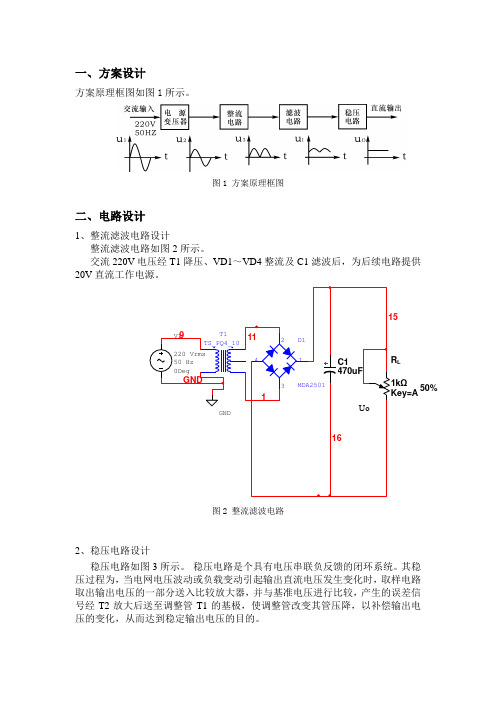
图1 方案原理框图二、电路设计1、整流滤波电路设计整流滤波电路如图2所示。
交流220V 电压经T1降压、VD1~VD4整流及C1滤波后,为后续电路提供20V 直流工作电源。
图2 整流滤波电路2、稳压电路设计稳压电路如图3所示。
稳压电路是个具有电压串联负反馈的闭环系统。
其稳压过程为,当电网电压波动或负载变动引起输出直流电压发生变化时,取样电路取出输出电压的一部分送入比较放大器,并与基准电压进行比较,产生的误差信号经T2放大后送至调整管T1的基极,使调整管改变其管压降,以补偿输出电压的变化,从而达到稳定输出电压的目的。
L50%图3 稳压电路3、输出参数调节及负载电路输出参数调节及负载电路如图4所示。
(1)输出电压Uo 及输出电压调节范围:)U (U R R R R R U BE2Z W 22W 1O +"+++=调节Rw 可以改变输出电压Uo 。
(2)最大负载电流Iomax 。
稳压电源正常工作时能输出的最大电流。
调节Rl 可以改变Io 。
50%Q1图4 输出参数调节及负载电路三、电路测试切断工频电源,连接好被测电路。
1、初测。
稳压器输出端负载开路,断开保护电路,接通220V工频电源,调节电位器Rw,观察Uo的大小和变化情况。
观察结果显示,Uo岁Rw线性变化,说明该稳压电路各反馈环路工作基本正常。
2、测量输出电压可调节范围。
接入负载,并调节Rl,使输出电流Io≈100mA,此时接入的负载阻值为156Ω,满足驱动负载在120Ω~240Ω的范围内,如图5所示。
再调节电位器Rw。
当将电位器Rw调节到最大值时,测量输出电压达到限定范围的最小值,此时Uo为6V左右,如图6所示;当将电位器Rw调节到最小值时,测量输出电压达到限定范围的最大值,此时Uo为15V左右,如图7所示,即满足稳压电源输出直流可调电压6V<Uo<15V这一技术指标的要求。
该过程中如不满足要求,可适当调整R1、R2的值。
1.25A高效开关稳压器- LT1072 1072fc说明书

1231072fcSYMBOL PARAMETER CONDITlONSMIN TYP MAX UNITSV REF Reference Voltage Measured at Feedback Pin 1.224 1.244 1.264V V C = 0.8V ●1.2141.244 1.274V I B Feedback Input Current V FB = V REF350750nA ●1100nA gmError Amplifier ∆I C = ±25µA 300044006000µmho Transconductance ●24007000µmho Error Amplifier Source or V C = 1.5V150200350µA Sink Current ●120400µA Error Amplifier Clamp Hi Clamp, V FB = 1V 1.8 2.3V VoltageLo Clamp, V FB = 1.5V 0.250.380.52V Reference Voltage Line 3V ≤ V IN ≤ V MAX ●0.03%/V RegulationV C = 0.8V %/V A V Error Amplifier Voltage Gain 0.9V ≤ V C ≤ 1.4V500800V/V Minimum Input Voltage ●2.63.0V I QSupply Current 3V ≤ V IN ≤ V MAX , V C = 0.6V 69mA Control Pin ThresholdDuty Cycle = 00.80.9 1.08V ●0.6 1.25V Normal/Flyback Threshold on Feedback Pin0.40.450.54V V FBFlyback Reference Voltage l FB = 50µA 1516.317.6V ●1418V Change in Flyback Reference Voltage 0.05 ≤ I FB ≤ 1mA 4.56.88.5V Flyback Reference Voltage l FB = 50µA0.010.03%/V Line Regulation3V ≤ V IN ≤ V MAX (Note 4)%/V Flyback Amplifier Transconductance (gm)∆I C = ±10µA 150300650µmho Flyback Amplifier Source V C = 0.6V Source ●153270µA and Sink CurrentI FB = 50µA Sink ●254070µA BVOutput Switch Breakdown 3V ≤ V IN ≤ V MAX LT1072●6590 V VoltageI SW = 1.5mA LT1072HV ●7590 V LT1072S8●6080 VV SAT Output Switch ON Resistance (Note 2)I SW = 1.25A●0.61ΩControl Voltage to Switch Current Transconductance 2A/V I LIMSwitch Current LimitDuty Cycle = 50%T J ≥ 25°C ● 1.253 A Duty Cycle = 50%T J < 25°C ● 1.25 3.5 A Duty Cycle = 80% (Note 3)●12.5A ∆I IN Supply Current Increase 2535mA/A ∆I SW During Switch ON Time f Switching Frequency354045 kHz ●3347 kHz DC (max)Maximum Switch Duty Cycle 909297%Flyback Sense Delay Time 1.5 µs Shutdown Mode 3V ≤ V IN ≤ V MAX 100250 µA Supply Current V C = 0.05V Shutdown Mode 3V ≤ V IN ≤ V MAX100150250 mV Threshold Voltage●50300mVThe ● denotes specifications which apply over the full operatingtemperature range. Unless otherwise specified, V IN = 15V, V C = 0.5V, V FB = V REF , output pin open.Note 1: Absolute Maximum Ratings are those values beyond which the life of a device may be impaired.Note 2: Measured with V C in hi clamp, V FB = 0.8V.Note 3: For duty cycles (DC) between 50% and 80%, minimum guaranteed switch current is given by I LIM = 0.833 (2 – DC).Note 4: V MAX = 55V for LT1072HV to avoid switch breakdown.ELECTRICAL CHARACTERISTICS456The LT1072 is a current mode switcher. This means that switch duty cycle is directly controlled by switch current rather than by output voltage. Referring to the block diagram, the switch is turned “on” at the start of each oscillator cycle. It is turned “off” when switch current reaches a predetermined level. Control of output voltage is obtained by using the output of a voltage sensing error amplifier to set current trip level. This technique has several advantages. First, it has immediate response to input voltage variations, unlike ordinary switchers which have notoriously poor line transient response. Second, it reduces the 90 phase shift at midfrequencies in the energy storage inductor. This greatly simplifies closed loop fre-quency compensation under widely varying input voltage or output load conditions. Finally, it allows simple pulse-by-pulse current limiting to provide maximum switch protection under output overload or short conditions. A low-dropout internal regulator provides a 2.3V supply for all internal circuitry on the LT1072. This low-dropout design allows input voltage to vary from 3V to 60V with virtually no change in device performance. A 40kHz oscillator is the basic clock for all internal timing. It turns “on” the output switch via the logic and driver circuitry. Special adaptive antisat circuitry detects onset of saturation in the power switch and adjusts driver current instantaneously to limit switch saturation. This minimizes driver dissipation and provides very rapid turn-off of the switch.A 1.2V bandgap reference biases the positive input of the error amplifier. The negative input is brought out for output voltage sensing. This feedback pin has a second function; when pulled low with an external resistor, it programs the LT1072 to disconnect the main error amplifier output and connects the output of the flyback amplifier to the comparator input. The LT1072 will then regulate the value of the flyback pulse with respect to the supply voltage. This flyback pulse is directly proportional to output voltage in the traditional transformer coupled flyback topology regulator. By regulating the amplitude of the flyback pulse, the output voltage can be regulated with no direct connection between input and output. The output is fully floating up to the breakdown voltage of the transformer windings. Multiple floating outputs are easily obtained with additional windings. A special delay network inside the LT1072 ignores the leakage inductance spike at the leading edge of the flyback pulse to improve output regulation.The error signal developed at the comparator input is brought out externally. This pin (V C) has four different functions. It is used for frequency compensation, current limit adjustment, soft starting, and total regulator shutdown. During normal regulator operation this pin sits at a voltage between 0.9V (low output current) and 2.0V (high output current). The error amplifiers are current output (gm) types, so this voltage can be externally clamped for adjusting current limit. Likewise, a capacitor coupled external clamp will provide soft start. Switch duty cycle goes to zero if the V C pin is pulled to ground through a diode, placing the LT1072 in an idle mode. Pulling the V C pin below 0.15V causes total regulator shutdown, with only 50µA supply current for shutdown circuitry biasing. See AN-19 for full application details.Extra Pins on the MiniDIP and Surface Mount Packages The 8 and 16-pin versions of the LT1072 have the emitters of the power transistor brought out separately from the ground pin. This eliminates errors due to ground pin voltage drops and allows the user to reduce switch current limit 2:1 by leaving the second emitter (E2) disconnected. The first emitter (E1) should always be connected to the ground pin. Note that switch “on” resistance doubles when E2 is left open, so efficiency will suffer somewhat when switch currents exceed 100mA. Also, note that chip dissipation will actually increase with E2 open during normal load operation, even though dissipation in current limit mode will decrease. See “Thermal Considerations.”Thermal Considerations When Using Small Packages The low supply current and high switch efficiency of the LT1072 allow it to be used without a heat sink in most applications when the TO-220 or TO-3 package is selected. These packages are rated at 50°C/W and 35°C/W respectively. The small packages, however, are rated at greater than 100°C/W. Care should be taken with these packages to ensure that the worse case input voltage and load current conditions do not cause excessive die temperatures. The following formulas can be used as aLT1072 OPERATIO71072fcrough guide to calculate LT1072 power dissipation. For more details, the reader is referred to Application Note 19 (AN19), “Efficiency Calculations” section.Average supply current (including driver current) is:I IN≈ 6mA + I SW(0.004 + DC/40)I SW = switch currentDC = switch duty cycleSwitch power dissipation is given by:P SW = (I SW)2 • R SW • DCR SW = LT1072 switch “on” resistance (1Ω maximum) Total power dissipation is the sum of supply current times input voltage plus switch power:P TOT = (l lN)(V IN) + P SWIn a typical example, using a boost converter to generate *********************,dutycycleisapproximately 60%, and switch current is about 0.65A, yielding:l lN = 6mA + 0.65(0.004 + DC/40) = 18mAP SW = (0.65)2 • 1Ω • (0.6) = 0.25WP TOT = (5V)(0.018A) + 0.25 = 0.34W Temperature rise in a plastic miniDIP would be 130°C/W times 0.34W, or approximately 44°C. The maximum ambient temperature would be limited to 100°C (commercial temperature limit) minus 44°C, or 56°C.In most applications, full load current is used to calculate die temperature. However, if overload conditions must also be accounted for, four approaches are possible. First, if loss of regulated output is acceptable under overload conditions, the internal thermal limit of the LT1072 will protect the die in most applications by shutting off switch current. Thermal limit is not a tested parameter, however, and should be considered only for non-critical applications with temporary overloads. A second approach is to use the larger TO-220 (T) or TO-3 (K) package which, even without a heat sink, may limit die temperatures to safe levels under overload conditions. In critical situations, heat sinking of these packages is required; especially if overload conditions must be tolerated for extended periods of time.The third approach for lower current applications is to leave the second switch emitter open. This increases switch “on” resistance by 2:1, but reduces switch current limit by 2:1 also, resulting in a net 2:1 reduction in I2R switch dissipation under current limit conditions.The fourth approach is to clamp the V C pin to a voltage less than its internal clamp level of 2V. The LT1072 switch current limit is zero at approximately 1V on the V C pin and 2A at 2V on the V C pin. Peak switch current can be externally clamped between these two levels with a diode. See AN-19 for details.LT1072 SynchronizingThe LT1072 can be externally synchronized in the frequency range of 48kHz to 70kHz. This is accomplished as shown in the accompanying figures. Synchronizing occurs when the V C pin is pulled to ground with an external transistor. To avoid disturbing the DC characteristics of the internal error amplifier, the width of the synchronizing pulse should be under 1µs. C2 sets the pulse width at ≈ 0.35µs. The effect of a synchronizing pulse on the LT1072 amplifier offset can be calculated from:KT=26mV at 25°Cqt S=pulse widthf S=pulse frequencyI C=LT1072 V C source current (≈ 200µA)V C=LT1072 operating V C voltage (1V to 2V)R3=resistor used to set mid-frequency “zero” in LT1072 frequency compensation network.With t S = 0.35µs, f S = 50kHz, V C = 1.5V, and R3 = 2KΩ, offset voltage shift is ≈2.2mV. This is not particularly bothersome, but note that high offsets could result if R3 were reduced to a much lower value. Also, the synchronizing transistor must sink higher currents with low values of R3, so larger drives may have to be used. The transistor must be capable of pulling the V C pin to within 200mV of ground to ensure synchronizing.LT1072 OPERATIO∆V OS =(t S)(f S) I C +I CKTq(((V CR3(81072fc91011121314Information furnished by Linear Technology Corporation is believed to be accurate and reliable. However, no responsibility is assumed for its use. Linear Technology Corporation makes no represen-tation that the interconnection of its circuits as described herein will not infringe on existing patent rights.1516LW/TP 1102 1K REV C • PRINTED IN USALINEAR TECHNOLOGY CORPORA TION 1988Linear Technology Corporation1630 McCarthy Blvd., Milpitas, CA 95035-7417(408) 432-1900 ● FAX: (408) 434-0507 ● 。
SZBTN系列调零调压稳压器中文使用说明书120520

5
SZBTN 系列调零调压稳压器使用说明书
右,当稳压器输入电压低于 320V 左右时,欠压继电器 J3 延时 30 秒左右吸合,与其相对应的 黄色发光二极管亮,通过控制接触器 KA2 吸合(接触器 KA1 会提前释放断开),稳压器输出电 压将自动上升 25%左右;当稳压器的输入电压高于 320+5V 以上时,欠压继电器 J3 延时断开, 与其相对应的黄色发光二极管灭,接触器 KA2 断开,然后升压继电器 J1 将从新返回吸合状态, 接触器 KA1 吸合,稳压器输出电压自动上升 10%左右。
输入 输出 电压 电压 (V) (V)
相 数
三 285 356 ~~ 420 420 相
165 206 单 ~~ 242 242 相
耐 压
2000V 10mA 1分 钟无 击穿
1500V 5mA 1分 钟无 击穿
绝缘 电阻 (MΩ)
≥5
效 率
≥ 99%
≥ 99.5
%
≥ 99%
波形 畸变
静态 ≤ 0.1%
SZBTN 系列调零调压稳压器使用说明书
一、概 述
致用户:谢谢您选购我厂的电源产品,请您在使用前详细阅读本说明书,以便您的工作 顺利进行。
SZBTN(DZBTN)系列三(单)相大功率调零调压稳压器是我厂结合我国偏远农村电网实 际情况而专门设计的特殊升压稳压产品。当农村供电线路过长,电压波动或负载变化造成电 压波动过大时自动保持输出电压在设备允许范围内,以保证后续电气设备的正常使用。
当稳压器的输入电压继续升高于设定值 356+5V 以上时,升压继电器 J1 断开,与其相对应 的绿色发光二极管灭,接触器 KA1 也将断开,此时稳压器输出电压等于输入电压,稳压器返 回到自动直通工作状态。
LH-100型稳压器说明书

一、产品概述市场中的节电装置大都不具备稳压的功能,仅仅降低装置的供电电压,从而达到节电的目的。
其弊端为:当电网电压稍有波动时,装置的输出电压升高,不再节电;或者输出电压降得更低,对负载的影响较大。
由此可见,稳压功能是节电装置必备的一项功能,也是能够实现节电的必要条件。
LH-100型智能节电装置根据用户电网电压的波动情况、照明负载的性质,为负载提供稳定的供电电压。
用户可根据需求,设置输出电压,对负载的运行时间和供电方式进行编程,最大限度地降低负载的电耗。
二、结构它是由三相补偿变压器、三相调压变压器、传动机构、电刷接触系统、箱体和控制系统等组成。
三相调压变压器圆筒式绕组外表面经磨光加工,去除绝缘,呈光滑的导体面,以便于电刷良好接触;传动机构由电动机和蜗轮、蜗杆、链轮、链条组成;电刷系统结构合理可靠,以保证电刷压力;箱体采用封闭柜式,体积小,散热好,检测仪表位置醒目,提示准确。
三、工作原理LH-100系列节电装置由三相补偿变压器TB、三相调压变压器TUV电压检测单元、电动机控制与传动机构,接触操作电路等组成,其电气原理图一所示。
图一自动补偿电力稳压器电气原理图调压变压器TUV的一次绕组接成Y形,连接在稳压器的输出端,二次绕组连接补偿变压器TB的一次绕组,而补偿变压器工作原理,如图二所示。
若不计补偿变压器阻抗压降,则从图二可见:Uao=Uai+Uac式中:Uai—稳压器A相输入电压;Uao—稳压器A相输出电压;Uac—稳压器A相补偿电压;图二单相补偿电力原理图其原理是:当A相输入电压Uai增加ΔUai时,补偿电压Uac也相应改变ΔUac且ΔUac=-ΔUai时,使A相输出电压Uao保持不变,同理B相、C相也是如此。
其稳压调压过程是:根据输出电压的变化,由电压检测单元采样,检测并输出信号控制电动机SM转动,经减速机构并有链条带动调压变压器TUV上的电刷组滑动(或滚动)来调节调压器的第二次电压,以改变补偿电压的极性和大小,降低或升高输出电压,进而达到节电的目的。
电子稳压传输器 直接安装在通道字母或通道字母电缆穿孔套管的产品 说明书

Specifications and User’s GuideFor Direct Mount Inside Channel Lettersor Channel Letter Wire RacewaysFEA TURES AND BENEFITS:• Input Line Surge Protection • High Power Factor • 1/2” Conduit Nipple On Primary • Line & Load Regulated Output• 1/2” Conduit Nipple On Primary • Integral Sleeve GTO-10 Output Leads • Complies with CSA22.2, No. 107.1, No. 13• Can be Direct Mounted on Rigid Sign Face Material (UYMR2)• Ground Connection via Mounting Foot•Will not T rip on Capacitive Currents up to 15mA•Open Circuit, Overload and Ground Faults Will Shut Unit DownDABECDIMENSIONS:Length (A) 6.65 in. (16.89 cm) Width (B) 3.13 in. (7.95 cm) Height (C) 1.55 in. (3.94 cm) Mounting (D) 6.13 in. (15.57 cm) Mounting (E)2.25 in. (5.7 cm) Weight23.0 oz. (652 gr) Primary Leads 36 in. (91.4 cm) GTO Leads32 in. (80.0 cm)SPECIFICATIONS:Input Voltage 120 VAC (±10%) 50/60Hz Input Current 0.6 A rms Power Factor 0.95Output Frequency Variable Output Voltage 100V - 4000V Output Current 60mA Operating T emperature -30° to 122°F (-34° to 50°C)Driving Distance (Based on Standard 12mm tube. Deduct one foot from drivingfootages for each pair of electrodes)Neon 1-10 ft, (0.25-3.1 m)Mercury 1-12 ft, (0.25-3.7 m)VT 4060CL-120Specifications and User’s Guide For Direct Mount Inside Channel Letters or Channel Letter Wire RacewaysThank you for purchasing a Ventex electronic neon transformer. Please read the following tips and directions carefully to insure proper installation and operation of our products. It is the responsibility of the user to ensure installation complies with local electrical codes.READ CAREFULL Y BEFORE INSTALLA TION 1. Contact with the transformer’s high voltage outputleads can cause shock, burn or death.2. The power supply’s grounding wire must be connectedto ground.3. Be sure the high voltage output leads are connectedfirmly to the gas tube(s) and electrodes are properlyinsulated before engaging power. Intermittentconnection of high voltage wires can cause hazardous arcing.4. High voltage leads and gas tubes should be at least1inch away from all surfaces.5. Output leads should not be grounded.6. Output leads cannot be run in metal conduit.7. When operating two or more power supplies in thesame installation, be sure units are mounted at least 12 inches apart.8. T ransformer can be mounted directly inside channelletter and/or mounted on the back wall, underneathtubes.9. T ransformer should not be mounted in a positionwhere it can stand in water.10. T ransformer is provided with GTO grommets whereGTO leads exit the unit. It is recommended GTOsleeving be used.INST ALLATION AND OPERA TION1. Firmly secure the transformer to the application withproper size screws or pop rivets.2. If transformer is mounted on key steel or metallicsurface, make sure transformer is grounded to metalframe via ground plate provided on unit. Insure all H-Voutput leads and tubes are at least 1 inch away frommetal.3. Firmly connect high voltage output leads to electrodesof the gas tube(s).4. Wire the power supply to any standard, three wire, 120,220/240 or 277 VAC (depending on model) groundedpower.5. Follow all applicable UL, NEC and local codes.TROUBLE - SHOOTING TIPSThere is a protection circuit in the transformers that will cut off (trip) the power whenever an open circuit or overload condition occurs. If your gas tube (sign) is off, and the input power is flowing, your transformer has probably tripped due to one of the above fault conditions. If so, follow procedure outlined below.Remove power to the transformer. This action will reset the protection circuit. Wait at least 10 seconds before reapplying power. If tripping continues, remove power and check the following:1. Are the output leads connected securely and properlyto the gas tube(s)?2. Is the gas tube broken or cracked, resulting in an opencircuit?3. Are the gas tubes or H-V output leads in closeproximity to metal, or any ground plane? (This maycause tubes to dim.)4. Are multiple units mounted at least one foot apart fromeach other?After completing the above check list and rectifying any detected problems, engage the input power to the transformer to (re)energize the gas tube (sign). If the transformer still does not work properly, call customer service at the listed phone number.Note: Do not attempt to disassemble transformer for repairs. This action will void any warranty made by Ventex.。
ME6119 400mA LDO 线性稳压器说明书
400mA 带载、18V 耐压、低压差快速响应LDO概述ME6119是一款高精度、低噪声、低压差、保护功能齐全的的LDO 线性稳压器,输入电压最高可达到18V ,输出电压精度在±2%。
芯片内置限流保护电路、短路保护电路和热关断电路,能有效防止发热或大电流负载情况下对芯片造成的损伤。
ON/OF 电路的使能脚能够关断输出电压,从而大大降低系统功耗。
特点 ● 最大输出电流:400mA● 低压差:104mV@ IOUT =100mA ● 工作电压范围:2.5-18V ● 输出电压精度:± 2%● 低静态功耗:60uA (典型值) ● 电源调整率:30mV (典型值) ● 温度稳定性:≤0.5% ● 热关断保护: 164℃应用场合● 消费类和工业设备供电 ● 开关电源的后级稳压 ● 驱动控制器封装形式● 3-pin SOT89-3、SOT23-3 ● 5-pin SOT23-5典型应用图选购指南ME 6119X X G环保标志封装形式X 功能产品类型产品系列公司标识X X 输出电压P-SOT89-3M5-SOT23-5M3-SOT23-3注: 目前,电压值有六种:3.0V 、3.3V 、3.6V 、4.0V 、4.4V 、5.0V 。
如需其他电压值或封装形式,请联系我司销售人员。
产品脚位图脚位功能说明ME6119AXX功能框图绝对最大额定值电气参数O=V注:1. V OUT (T) :规定的输出电压2.V OUT (E) :有效输出电压 ( 即当I OUT 保持一定数值,V IN = V OUT (T)+1.0V 时的输出电压。
)3.V DIF:V IN1 –V OUT (E)’V IN1 :逐渐减小输入电压,当输出电压降为 V OUT (E) 的98%时的输入电压。
V OUT (E)’= V OUT (E)*98%Type Characteristics (V OUT =5.0V )(1)Output Voltage VS. Output Current (2) Output Voltage VS. Temperature (VIN=V OUT +1V ) (VIN=V OUT +1V , I OUT=1mA )(3)Dropout Voltage VS. Output Current (Ta = 25 °C ) (4)Output Voltage VS. Input Voltage (I OUT =10mA )(Ta = 25 °C )(5)Quiescent Current VS. Input Voltage应用信息1. 输入电容的选择建议选用10uF的钽电容,可以兼容绝大多数的设备。
稳压器操作规程
稳压器操作规程稳压器操作规程一、稳压器的基本原理稳压器是一种电气设备,用于稳定输入电压,输出恒定的稳定电压,使电器设备在电网波动时保持正常的工作状态。
稳压器的基本原理是通过自动调节器件控制变压器中绕组的电压比例,使输出电压保持在设定的稳定值。
二、稳压器的使用环境1. 稳压器必须放置在干燥、通风良好的场所,远离水源、火源和腐蚀性气体。
2. 稳压器的安装位置应远离强磁场和电磁干扰源,以免影响稳压器的正常工作。
3. 稳压器的电源线应接在配电箱或独立的电源插座上,确保稳压器能独立供电。
三、稳压器的操作步骤1. 打开主电源开关,将电源线插入稳压器的电源插座,确保插头和插座连接良好。
2. 启动稳压器,根据需要调节输出电压的稳定值。
通常情况下,稳压器会配备手动调节装置,通过旋钮或开关来调节输出电压。
3. 稳压器启动后,通过观察面板上的指示灯或显示器,确认稳压器正常工作,并检查输出电压是否达到设定值。
4. 在正常工作时,稳压器会自动调节电压比例,使输出电压保持稳定。
如果需要改变输出电压,可以通过手动调节装置进行调节。
5. 稳压器的使用过程中,应定期检查稳压器的电源线是否有损坏,是否正常连接,以及面板上的指示是否正常。
6. 在长时间不使用稳压器时,应将主电源开关关闭,并将电源插头拔出插座,以节省电能和延长稳压器的使用寿命。
四、稳压器的维护保养1. 定期清洁稳压器的表面,防止灰尘进入内部导致故障。
2. 检查稳压器的散热器是否堵塞,保持良好的散热效果。
3. 定期检查稳压器的连接线路,确保电源线和输出线路无损坏,并紧固连接螺栓。
4. 如果发现稳压器运行异常或故障,应及时停止使用,并联系专业人员进行维修。
五、稳压器的安全注意事项1. 在操作稳压器时,应佩戴绝缘手套和绝缘鞋,以防止触电事故。
2. 禁止将金属物品或液体物质放置在稳压器上,以防止短路或损坏。
3. 禁止在潮湿的环境中使用稳压器,以防止漏电事故。
4. 当稳压器发生异常时,应立即停止使用,并断开电源,以避免进一步的危险。
稳压器操作规程范文
稳压器操作规程范文一、稳压器的基本原理和分类稳压器是一种能够将不稳定电压稳定在设定值范围内的电器设备。
它可以有效地保护电器设备,提高设备的稳定性和寿命。
在使用稳压器时,必须严格按照操作规程进行操作,以确保其安全有效地运行。
稳压器按照工作原理可以大致分为线性稳压器和开关稳压器两类。
二、稳压器的安装和检查1.稳压器的安装应在干燥、通风良好的场所进行,远离潮湿和易燃物品。
2.安装时应避免震动和振动,确保设备固定牢靠。
3.安装完毕后要检查稳压器的电源、负载等是否正确接线,并仔细检查接线部分的绝缘是否良好。
4.打开稳压器面板上的电源开关,稳压器的指示灯应亮起,表示已经接通电源。
5.对于大型稳压器,应有专人负责检查和维护,定期检查和清洁。
三、稳压器的操作1.根据所连接设备的功率需求,调节稳压器的输出电压。
一般情况下,输出电压应在额定电压的范围内。
2.稳压器的额定电压和额定电流是操作的重要参数,不得超过其额定值。
超过额定值将导致稳压器过载,影响其正常工作。
3.在调节稳压器输出电压时,应缓慢调节,不宜快速变动,避免对设备产生冲击和损坏。
4.在使用稳压器的过程中,不得随意关闭或拆卸稳压器。
如需停机、维修等操作,应先切断电源,等稳压器完全停止工作后再操作。
5.稳压器在工作过程中应注意观察指示灯的工作状态,如发现指示灯异常闪烁或灭了,应立即停止使用,并查找故障原因。
四、稳压器的维护和保养1.定期检查稳压器的通风孔和冷却设备,确保良好的散热。
2.清洁稳压器的外壳,不得使用湿布擦拭,以防止水分进入稳压器内部。
3.定期清洁稳压器的接线端子,检查接线端子的连接是否松动,如有松动应及时拧紧。
4.稳压器的维护和保养,应由专职人员进行,避免非专业人员进行维修。
五、稳压器的注意事项1.稳压器只能用于交流电电压稳定,不能用于直流电电压稳定。
2.长时间不使用稳压器时,应切断电源,并在室温干燥的环境中存放。
3.不得将稳压器受潮、进水或有明显损坏时继续使用。
75kVA稳压器使用说明书
· OYHS-8375 交流自动稳压器 说
明
书 使用前请认真阅读本说明书
1.稳压器使用功能说明书
感谢您选用了交流自动稳压器,愿我们的产品及服务能为您带来更多方便和实惠 功能:在市电输入变化时自动调整稳压输出,确保家用电器在恶劣的电网条件下也能正常运 行;同时具备了全方位保护及实用的稳压、市电直通功能,使用方便,更安全更可靠,大大 延长了家用电器的使用寿命。 ⊙ 稳压精确:在电网电压变化不稳时,能输出稳定的安全电压,使用电器不受影响。 ⊙ 输入欠压、过压保护:由电网及其他因素引起的电压输入过高或过低时,为保证用电器 和人身财产安全,稳压器会自动切断输出,待电网电压恢复稳定后可自动(延时)开启。 ⊙ 缺相保护:在三相供电情况下,由于一相断掉或者零线断掉,会导致单相供电电压异常 升高,甚至高过380V,危及到用电器及人身财产安全,此时稳压器会自动关闭输出进入保 护状态。 ⊙ 误断电保护:在遇到电网老化、输电线过细距离过长时,有感性负载(如冰箱、空调等 带有压缩机的)或大型用电器启动,瞬间会导致电网电压降低,此时稳压器能保证负载的正 常供电而不至于误断电。 ⊙ 市电稳压切换:机身侧面设有稳压接入和市电直通转换开关,使用时若觉得电网电压很 稳定,不想用稳压功能时,把此开关拨至“OFF”市电状态即可。通常情况下都要将此开关 拨至“ON”稳压状态,此时自动稳压功能才能启动。 ⊙ 延时供电功能:为避免短时间停电又来电情况的发生,设有了2-3分钟自动延时供电功能 (如电冰箱或空调器在停止工作后,再次启动需3分钟延时);若不需要此延时,可按下 “延时开关”按钮启动短延时,本机可在5接线安装方法
将启动开关拨至“OFF”关状态,拉下电网闸刀开关或空气开关断开市电,取下 稳压器端子板两颗固定螺丝拔出端子板,按对应端位指示正确连接 1.把家庭供电总线(墙壁插座及所有用电器用线)插入到对应输出的“火线”、 “零线”端口内,拧紧固定螺丝。 2. 把供电输入连接线插入到对应输入的“火线”、“零线”端口内,拧紧固定 螺丝。 3. 再把安全接地线插入到对应的(端子中间“接地”符号)端口内,拧紧固定 螺丝。 4.再次检查拧紧所有固定螺丝,把端子板固定好后合上供电闸刀开关或空气开关, 把面板启动开关打开,通电安装完成。 特别提醒:一定确保所有连接线压接牢固,避免工作时接触不良发热导致接线 板损坏!!! 面板指示:分别设有输入和输出电压表,指示灯指示工作状态;有供电输入时, 输入指示灯亮,市电电压表显示此刻电网电压高低;稳压输出时,对应输出 指示灯亮,输出电压表显示稳压输出值。
- 1、下载文档前请自行甄别文档内容的完整性,平台不提供额外的编辑、内容补充、找答案等附加服务。
- 2、"仅部分预览"的文档,不可在线预览部分如存在完整性等问题,可反馈申请退款(可完整预览的文档不适用该条件!)。
- 3、如文档侵犯您的权益,请联系客服反馈,我们会尽快为您处理(人工客服工作时间:9:00-18:30)。
国进稳压器说明书
1、打开包装,先检查外壳、电表、开关、指示灯、按钮、接线端子等有无损坏,无损坏的才能使用。
2、将输入端插到(或接到)配电板上,并在用户配电板上安上符合本设备功率的保险丝,以确保用电安全。
3、将用电设备的电源接到本设备的输出端上,注意使用电器适用电压是220V还是110V,切勿接错。
4、先开启稳压器的电源开关,工作指示灯、延时指示灯亮,无电输出,3-7秒后即送电,观察指示灯是否正常指示220V。
输出电压正常(220V)左右时,再开启用电设备电源开关。
本稳压器即能自动调整电压,正常供电。
5、当用电设备长期不用时,请关闭用电设备的电源开关,并关闭稳压器的电源开关,以减少耗电和延长稳压器使用寿命。
6、本稳压器不得过载使用。
市电电压较低时,输出容量减少,应相应减少稳压器的负载。
7、当用电器有冰箱、空调、水泵等有电机运转的设备时,应选择3倍以上的容量的稳压器,以免设备启动电流超过稳压器保险丝电流或过流保护断路器电流使稳压器保险丝熔断或断路跳闸而无法工作。
8、与稳压器连接的导线应有足够截面,防止发热和减少降压。
容量2KVA以上的稳压器采用端子连接,应选用单根铜质导线,并尽量拧紧端子螺丝,防止连接处发热。
9、部分稳压器面板上设有电压检测按钮,按入按钮电压表指示输入电压,可直接观察市电状况。
10、三相稳压器左边三个端子A、B、C接输入三相相线(火线),右边三个端子X、Y、Z接负载,中间两个接线端子接输入输出共用零线。
单相稳压器接线按端子盖板上的图示。
11、三相稳压器面板上的电压检测按钮按入和按出时分别指示AB和AC相线电压(380V),按钮和万能转换只能看作其中两项电压是否正常使用。
12、无论是单相或三相稳压器,在接好所有输入输出线后,应先关掉负载(用电器)的电源开关,再开启稳压器,检查输出电压正常后,再开启负载的电源开关。