EMD 710 TURBOCHARGER Manual
船舶主机滑油串油方法详解

(Flushing Procedure for Main L.O System & Main Engine)2009. 02. 01~7일HHI-EMD(Contents)内容(Contents)1.清洗目的(Flushing Purpose)2.润滑油的清洗范围(Scope of Oil Flushing)3.造船厂的主要润滑油清洗步骤(Flushing Sequence of Main Lube Oil Systems –Yard Line)4.主机清洗步骤(Flushing Sequence of Main Engine)5.绕过法兰盖的種類(Kinds of By-pass Blind Flange)6.错误清洗的案例(Case Study of Bad Flushing)1.清洗目的(Flushing Purpose)2.润滑油的清洗范围(Scope of Oil Flushing)3.造船厂的主要润滑油清洗步骤(Flushing Sequence of Main Lube Oil Systems –Yard Line)4.主机清洗步骤(Flushing Sequence of Main Engine)5.绕过法兰盖的種類(Kinds of By-pass Blind Flange)6.错误清洗的案例(Case Study of Bad Flushing)1)为了清除掉在主要润滑系统,存储箱和管道里的杂质(To remove particles in Main lube oil system, tanks and piping ,etc.)§喷砂处理(Sand blast)-砂, 鋼片§焊接(Welding)-桿, 棒, 淺(Spatters)§其他外来材料-衣料等(Other foreign materials -clothes, etc.)u 主机启动之前,所有润滑油要流进主机必须要对它进行清洗(All oil systems flowing into Main Engine must be flushed before Engine start-up)u 在连接主机管道之前,外部管子应该将汚染物等清洗掉(External pipes should be free of dirt and particles before connection to engine pipes2) 为了保持系统清洗油的质量(To maintain clean oil in the system.)§清洁NAS 9级(Cleanliness NAS grade 9)or ISO 4406 level 19/15( Pls contact HHI Supervisor for detail)3) 防止杂质流进主机(To prevent Main Engine from particle inflow.)l 所有轴承(All bearings) :主轴承(Main),十字头(X-head),曲拐销(Crankpin)l 曲轴颈和销(Crankshaft Journal & Pin)l 增压器(Turbocharger)l 凸轮和滚筒(Cam & Rollers)l 主链条和链轮(Main chain & Chain Wheels)l 其他运行部分(Other running parts)l 燃油泵(Fuel pumps)u 不合适的清洗将导致严重损坏(Improper flushing shall result in serious damage on engine components)2. 润滑油清洗范围(Scope of Oil Flushing)NORMAL OPENMain EnginePURIFIER(5 μm)2. 润滑油清洗的范围(Scope of Oil Flushing)u主机系统(Main Engine Systems)1.主轴承润滑油管道(Main Bearing L.O Line)2.适塞冷却/十字头轴承润滑油管道(PCO/Crosshead Bearing L.O Line)3.凸轮轴承&排气阀润滑油管道(Cam Bearing & Exh. valve L.O Line)4.链条盒的润滑油管道(Chain Case L.O Line)5.增压器润滑油管道(Turbocharger L.O Line)6. Others & Optional Parts3. 船厂管道主要润滑油系统清洗(Flushing of Main L.O Systems –Yard Line)NORMAL OPENBy-pass LineMain EnginePURIFIER(5 μm)3. 船厂管道主要润滑油系统清洗(Flushing of Main L.O Systems –Shipyard Line)NORMAL OPENMAIN ENGINE PIPE LINEBy-pass LineMain EnginePURIFIER(5 μm)By-pass hose3. 船厂管道主要润滑油系统清洗(Flushing of Main L.O Systems –Yard Line)NORMAL OPENMAIN ENGINE PIPE LINEBy-pass LineMain EnginePURIFIER(5 μm)Check bag3.船厂管道主要润滑油系统清洗(Flushing of Main L.O Systems –Yard Line)NORMAL OPENMAIN ENGINE PIPE LINEBy-pass LineMain EnginePURIFIER(5 μm)4.主机清洗顺序(Flushing of Main Engine)4-1 Preparations & Check before Flushing v Attention!注意!船厂的清洗工作非常重要为了保持已清洗好的发动机要跟着第3章的步骤进行清洗工作.HHI已准备好帮助船厂做清洗工作.Shipyard flushing is so important to keep M/E & vessel’s service.Flushing procedure on Chapter 3 should be followedto keep engines of already flushed and cleaned condition.HHI are ready to support shipyard & M/E flushing on request.为了更干净的质量和省事(For better cleanness quality and saving works)1. 跟着第三章所显示,检查润滑油的清洁和外管系统(To check the L.O cleanness and the external piping system as Ch 3,By means of checkbags and recommended particle counting)2.和HHI-EMD服务工程师一起检查主机的清洁程度(To consult M/E clean condition & scope of flushing with HHI-EMD service engineer/inform HHI of M/E status)3.如需要,HHI可以提供更多的说明和派专家(HHI can support more detail instruction & delegate specialist on shipyardrequest)4. Main Lub. Oil flushing(Yard+Engine Line)Crossheadpinopen space4.主机清洗顺序(Flushing Sequence of Main Engine)2383414-3 Main Engine Inside Flushing &Location of blind flange①拆下到主机的主要管道Main bearing pipe line ②曲拐箱里的十字头轴承(活塞冷却油)Cross head bearing (PCO) pipe line ③Main chain, cam & exh.valve drive pipe line ④Thrust bearing pipe line ⑤Axial vibration damper pipe line ⑥Torsional vibration damper pipe line(Option)⑦Moment compansator chain drive line(Option) ⑧增压器管道Turbo charger Lub.oil line⑨Hydraulic chain tightener pipe line(Option)4.主机清洗顺序(Flushing Sequence of Main Engine)Mount between main brg.cap& L.O. pipe Nord lock washerAttention ! Correct use of Nord lock washer(see page 23)Be careful of falling down into chamber /crankjournalNord lock washer4. 主机清洗顺序(Flushing Sequence of Main Engine)1.Dismantle PCO boltsonly one cylinder first at BDC 2. Lift PCO pipe 3. Mount by-pass blind flangeonly one cylinderBe careful of falling down into chamber / crank journal4. After one blind mounting,Check the gap 2mmbetween bolts at TDC 5. If bolt head touched, at least two bolts looseGap : Min. 2mm6. Mount by-pass blind on all cylindersBy-pass HoseConnection1.T/C Inlet pipe to be disassembled 2.By-pass hose to mount and connect with drain line underside.3.L.O for T/C inlet should be by-passed & flushed during a whole period of flushingT/C underside& Inlet pipeDrain line undersidegrating4-3-4. Main chain & Chain wheel bearing blind flange4-3-5. Thrust pad & aft.most bearing blind flange4-3-6. Axial vibration damper blind flangeAFT.Side4-3-8. 2’nd moment compensater blind flangePURIFIER (5 μm)MainEngineCheck bagNORMAL OPEN MAIN ENGINE PIPE LINE By-pass LinePURIFIER (5 μm)MainEngineCheck bagNORMAL OPEN MAIN ENGINE PIPE LINE By-pass Line1) Main Bearing By-pass2) P.C.O. Line By-pass1. Dismantle Inlet Pipe2. Check pipe inside 1. Lift P.C.O. pipe about 300mm2. Check pipe inside & guide shoe inletby means of eye & fingers300mmFinally, tighten the bolts with Nord lock washer as page 23.Do not separate like two washer. It works together all the time !!!normal bolt Counterbored holeMust Put it Both side Prevent loosing Do not use with other washersat the same time4. 主机清洗顺序(Flushing Sequence of Main Engine)24 354.主机清洗顺序(Flushing Sequence of Main Engine)15-2. Various Kinds for PCO/Cross head Bearing Bad ( x )-No weldingNormal, But to be improved ( O )Bad ( x )58M16X3551093030308M12X9080M12X7080M12X9080Bolt7Φpipe9A > > min.10C > 2mmIn case of S60MC-C ; A > 6.5 , A+B < 9.5 (ΦDrawing at the T.D.C point5252447862754478Chain wheel brg.2’ndMoment(F)2’ndMoment(A)5-6. Sample to insert blind flange 1mm5.绕过法兰盖的種類(Kinds of By-pass Blind Flange)12323主轴承颈(Main Journal)下部主轴承(Main bearing lower part)6-2. Gasket Piece Falling into Guide Shoe -PCO inletDuring M/E reassembly on board, gasket piece flowing into guide shoe inlet through PCO pipe lineGuide Shoe,PCO inletGasket Piece1122曲拐销(Crank pin)曲拐销轴承上部(Crank pin bearing upper)(Foreign particle in Crank pin bearing lower bearing by failure Of Oil flushing)曲拐销轴承下部(Crank pin bearing lower)电焊废渣(Welding slag)下部主轴承(Main bearing lower part)6-6. 由于润滑油清洗失败而导致活塞&汽缸套损坏(Piston & Cyl.liner damage by failure of oil flushing)润滑油管道&法兰(Lub. Oil pipe &flange)Important Point of Oil flushing1) Ship Yard Pipes Must Be Clean inside before Installing. 安装前,船厂管道必须保持干净.2) Ship Yard system must be flushed by using Vibrators.使用振动器,船厂系统必须清洗.3) Correct Installation of by-pass blank.纠正绕过管的安装.4) Check pipe inside before dismantling by-pass blanks.拆开旁通管之前,要检查管的内部.5) HHI are ready to support shipyard flushing workSummary of Oil FlushingThank You엔진기계사업본부主机润滑油系统清洗步骤(Flushing Procedure Main L.O System & Main Engine)2009. 02.。
M2M-710D快速入门指南说明书

M2M-710D Quick Start User Guide1. IntroductionThis manual introduces the M2M-710D’s basic setting and operation. The user can refer to the user manual in the ICP DAS companion CD-ROM (Path: CD:\napdos\multimedia\M2M-710D\manual\M2M-710Duser manual.pdf”)The manual is intended to help users quickly understanding and easily using of M2M-710D. In this demo, one M2M-710D is set as client mode and the other is in server mode. One Ethernet switch and one PC to make a simple application here, as shown in figure 1. The PC is prepared for setting the M2M-710D.Figure 1: Pair connection2. Hardware configurationM2M-710DM2M-710D Pin definitionPin Name Description1 CTS1 Clear to Send2 RTS1 Request to Send3 RxD1 Receive Data4 TxD1 Transmit Data5 INIT InitPin6 DATA+ Data+ of RS-4857 DATA- Data- of RS-4858 Vs Vs of Power Supply9 GND GND of Power SupplyDigit Led DisplayState Step DescribePower on 11111 Show local IP step by step 22222 Show Server IP step by step 33333 Show connected port for server 44444 Show Comport configurationconnectconnecting The word “Conn.” twinkledLogi n Display the word “Conn.”serial port Show information of alternate port and Baudrate3. System SettingThe M2M-710D module is built-in web server, the user can configure and operate the M2M-710D by web browser (ex: IE).Connection SettingThe user needs to prepare a system like figure 1. The user can connect PC and a M2M-710D by Ethernet switch. It can not connect with two M2M-710D at the same time before setting.M2M-710Ds’ IPs will conflict, because M2M-710D’ default IPs (Default IP address is “192.168.1.217”) are the same. The connection setting will be described below and Microsoft Windows XP Professional SP2 is used.a. Setting the Network of PC :Set the IP and Subnet mask of the PC. These settings must have the same domain and different IP with the M2M-710D. (ex: M2M-710D’s default IP = 192.168.1.217, PC’s IP = 192.168.1.210).Step 1: Click “start->Settings->Network Connections”. Step 2: Double click “Local Area Connection” icon. Step 3: Click “Properties” button.Step 4: Select “Internet Protocol(TCP/IP)” and click “Properties” button. Step 5: Set “Internet Protocol Properties” and then click “OK” button.Step 1: Click “Network Connections” Step 2: Click iconStep 3: Click “Properties” button Step 4: Click “Properties” buttonStep 5: Set “Internet Protocol Properties”b. connection test:Step 1: Click “start->Run” Step 2: key in “cmd” and then click “OK” button Step 3: Key in “ping 192.168.1.217” and click “Enter”. If the network settings are all correct in PC and M2M-710D, these messages are shown below. Response Message:Reply from 192.168.1.217: bytes=32 time<1ms TTL=64Reply from 192.168.1.217: bytes=32 time<1ms TTL=64Reply from 192.168.1.217: bytes=32 time<1ms TTL=64Reply from 192.168.1.217: bytes=32 time<1ms TTL=64Ping statistics for 192.168.1.217:Packets: Sent=4, Received=4, Lost=0 (0% loss)c. Set Client:Open web browser (ex: IE, Mozilla, etc.) on PC and key in http://192.168.1.217/main.htm in the Address line and then press “Enter” key to link the M2M-710D’s web page.Key in user name and password and then click “Enter” button to login.Set Host Name = “M2M-710D”, Operation Mode = “Client” , ServerIP = ”192.168.1.217” and IP Address = “192.168.1.218” in “Standard Config” web page. It is not need to change the other settings and, thenclick “Save Setting” button to save the settings.Click “Reboot” button to reset M2M-710D in the left page.d. Setting ServerNow the user can connect the other M2M-710D and Ethernet switch and don’t need to remove the Client after the Client finished setting. If the Server has default settings, it can work in the demo.The Client will try to establish the connection with the Server after the Server and Client power on. If PWR is on, SA1 is off and SA2 flash slowly one minute later, it means the Server and Client work normally and ready to use.e. Error checkIf these led statuses are not the same as the above, check the power supply,network connection and system settings again.Server: The user can open web browser and give the network address:http://192.168.1.217/main.htm . After login, the user can click “DefaultSetting” button and then click “Save Setting” button to recover the defaultsettings in the “Standard Config” page.Client: The user can open web browser and give the www address:http://192.168.1.218/main.htm . After login the user can click “Default Setting”button in the “Standard Config” page and then set the client refer to the above.Note: It must reset the M2M-710D by power reset or click “Reboot” button after the user changes the settings.4. Communication testIf the above settings are all correct, the Server and Client should work normally. Open web browser and give the network address: http://192.168.1.217/main.htm and then click Information page. If System State condition is “Communication” or you can find out client IP in Operation Mode page, both sides already established the communication.System statesides already established the communication.Check Client IP on Operation Mode pageAfter accomplish setting, then tests M2M-710D’s function using HyperTerminalApplet. The RS232 material which tests on PC to send out may transmit correctly from any one to another tests PC.。
数码相机 EZshot E710 说明书

更换锂电池 电量低图标开始在 LCD 上闪烁时,即表示电池电量不足,您需要通过 USB 数据线将相机连接到计算机 上进行充电。充电时,一个红色 LED 灯将亮起,充满电后自动熄灭。
8
安装 SD 存储卡 本款相机最大支持 4GB 兼容的 SD 存储卡。相机内置内存有限,仅供测试拍摄用。关闭相机电源,或取 出电池后,内置内存中的照片将丢失。要正常使用相机,您需要安装 SD 存储卡。请参照下图正确安装:
计算机系统要求 (Windows Vista)
要将照片和视频下载到计算机上,系统配置最低要求为: y Windows Vista y 800MHz 处理器,512MB 系统内存 y 20GB 硬盘,至少 15GB 可用空间 y 支持高级视频图形阵列 (SVGA) y 可使用 USB 接口 y CD-ROM 驱动器
4
相机模式
本款相机有 3 种模式: • 相机模式: 拍摄静止照片 • 摄像模式: 拍摄视频 • 播放模式: 查看、打印、编辑照片以及查看视频
5
LCD 上的主要图标
6
电池电量
满格电量 半格电量 电量低
照片质量
标准 高
闪光灯
强制闪光 自动
无
模式
相机
摄像
场景
自动 人像 集会
播放
间人像 景物
海滩
间景物 运动
发送照片;等等
相机包装所含物品
y 数码相机 y PhoTags Express 软件安装 CD y USB 数据线 y 用户手册 y 肩带 y AC 適配器 (optional)
2
计算机系统要求 (Windows 2000/XP)
要将照片和视频下载到计算机上,系统配置最低要求为: y Pentium 处理器或以上,操作系统为 Windows 2000 或 XP y 128MB RAM、125MB 以上可用硬盘空间 y 可使用 USB 接口 y CD-ROM 驱动器 y 我们推荐您将显示器的分辨率为设置为 1024 X 768 或更高 y 16 位色或更高的显示适配器
Magnum Mobile Generator MMG175 产品说明书

Mobile Generator – MMG175 SpecificationsENGINE∙John Deere® PE6068HFG94 - turbocharged, diesel engineo Prime - 217 hp @ 1800 rpmo Standby - 241 hp @ 1800 rpmo 6 cylindero 6.8 L displacemento Interim Tier IV emissions∙Steel, single wall fuel tanko342 gal. capacityo29 hr. run time – full loado Fuel tank built into skid of generator set∙Fuel consumption at prime:o100% - 10.9 gph (41.3 Lph)o75% - 8.2 gph (31.0 Lph)o50% - 5.5 gph (20.8 Lph)∙Cooling system capable of operating at 120°F ambient∙Low coolant shutdown∙Radiator and oil drains plumbed to exterior∙Rubber vibration dampers isolate engine/generator from frame∙Disposable air filter - paper element∙Air filter restriction indicator mounted on control panel∙60 Hz engine/generator∙Electronic isochronous governing∙Utilizes DOC / DPF exhaust filter∙Variable Geometry Turbocharger (VGT)GENERATOR∙Marathon Electric®o Brushlesso 4 poleo Class H insulation∙Voltage regulation +/- 1% with Marathon SE350 Voltage RegulatorSYSTEM OUTPUT∙ 3 Position voltage selector switch:o Three phase – 120 / 208V Low Wyeo Three phase – 277 / 480V High Wyeo Single phase – 120 / 240V Zig Zag∙153 kW / 191 kVA – standby, three phase∙138 kW / 172 kVA – prime, three phase∙125 kW / 125 kVA – standby, single phase∙120 kW / 120 kVA – prime, single phaseSYSTEM CONTROLS∙Microprocessor-based controllero Backlit, 128x64 pixel resolution displayo-40°F to 185°F operating temperature rangeo Thermostatically controlled LCD heater Array o Six LED indicators w/ lamp test♦Alarm / Fault (Red)♦Ready / Manual (Red)♦Running (Green)♦Warning (Yellow)♦Ready / Auto (Green)♦Supplying Load (Green)∙Push buttons for easy operationo Manual or Auto Starto Engine Start or Stopo Alarm Cancel & Fault Reseto Scrolling Arrows for Diagnostic Information♦System kW output display♦Line output & frequency display♦Engine diagnostic display∙Oil pressure∙Engine temperature∙Fuel level∙Battery♦System hours∙Running hours∙kW hours∙Time to serviceo Alarm list – warnings / shutdowns are date & time stamped♦Fuel level: warning – 15%; shutdown – 5%♦Overspeed protection: shutdown – 115%♦Oil pressure: warning – 25 psi; shutdown – 20 psi♦Coolant temperature: warning – 220°F; shutdown – 230°F♦Battery voltage: over – 15VDC; under – 11VDC♦Generator over voltage: warning – 110%; shutdown – 111%♦Generator under voltage: warning – 87%; shutdown – 86%♦Generator over frequency: warning – 105%; shutdown – 110%♦Generator under frequency: warning – 95%; shutdown – 90%♦Over current shutdownELECTRICAL CONTROLS∙Remote start / stop contacts located next to lug box∙Lockable control box door with diagnostics window∙Lockable lug box with safety switcho Trips main breaker when lug door is openedDisables voltage regulator∙Cable entry guides to the lug boxo Restricts access of foreign objects∙Output ground connection lug inside lug box∙700A main breaker with shunt trip∙Convenience receptacles with individual breakers (restricted use in high wye mode) o(2) 120V 20 Amp GFCI duplex outlets (Nema 5-20R type)o(3) 125 / 250V 50 Amp, 3 pole, 4 wire twistlock (Non-Nema 6369) ∙Panel mounted rheostat for voltage adjustment - +/- 10%∙1000 CCA wet cell batteryENCLOSURE∙Generac Mobile Power decals∙Aluminum, sound attenuated enclosureo UV & fade resistant, high temperature cured, white polyester powder painto Insulated and baffledo68 dB(A) at 23 feet – prime power∙Fully lockable enclosure including doors and fuel fill∙Stainless steel hinges on doors∙Emergency stop switch located on outside of enclosure∙Central lifting point∙Multi-lingual operating/safety decals∙Document holder with operating manual including AC/DC wiring diagramsTRAILER∙DOT approved tail, side, brake, and directional lightso Recessed rear lights∙Transportation tie downs∙Safety chains with spring loaded safety hooks∙3” lunette ring hitch∙(2) 7000 lb. axles with surge brakes∙5000 lb. tongue jack with footplate∙ST235/80R16 tubeless tires – 10 plyWEIGHTS & DIMENSIONSmountedSkid∙Dry weight: 6604 lbs (2996 kg)∙Operating weight: 9032 lbs (4097 kg)∙144 x 50 x 77 in(3.66 x 1.27 x 1.96 m)Trailer mounted∙Dry weight: 8000 lbs(3629 kg)∙Operating weight: 10426 lbs (4730 kg)∙210 x 86 x 93 in(5.33 x 2.18 x 2.36 m)WARRANTY∙Engine and generator covered under OEM warranty – consult factory for details. CERTIFICATIONS∙CSA certifiedMMG175 OptionsENGINE OPTIONS♦In-line engine block heater (Kim Hotstart)♦Fuel transfer pumpELECTRICAL CONTROLS OPTIONS♦Battery disconnect♦Battery charger – 2A trickleGENERATOR OPTIONS♦PMG Generator - critical grade power quality♦Super Start Generator - motor starting applicationsVOLTAGE OUTPUT OPTIONS♦ 4 position phase switch▪Single phase – 120 / 240V Zig Zag▪Three phase – 120 / 208V Low Wye▪Three phase – 277 / 480V High Wye▪Three phase – 120 / 240V Delta♦Dedicated voltage configurations♦Buck Transformer kit - Provides 120V at GFCI outlets when in 277/480V ♦Cam locksSYSTEM CONTROLS OPTIONS♦Auxiliary strobe/audible indication for soft & hard alarm conditionsCOOLANT OPTIONS♦60/40 Coolant - cold weather applicationsENCLOSURE OPTIONS♦Fire extinguisher♦Interior cabinet light♦Control panel lightFUEL TANK OPTIONS♦120% ContainmentTRAILER OPTIONS♦Tandem axle trailer w/ electric brakes♦ 6 pin or 7 spade electrical connectors♦Spare tire/wheel kit。
Micrel LMC7101 低功耗操作放大器说明书

Typ Min Max Min Max
VOS
Input Offset Voltage
0.
TCVOS IB IOS RIN
Input Offset Voltage Average Drift Input Bias Current Input Offset Current Input Resistance
............................................. VV+ + 0.3V to VV– – 0.3V Junction Temperature (TJ) ...................................... +150°C Storage Temperature ............................... –65°C to +150°C Lead Temperature (soldering, 10 sec.) ..................... 260°C ESD, Note 5 .................................................................. 2kV
Micrel, Inc. • 2180 Fortune Drive • San Jose, CA 95131 • USA • tel + 1 (408) 944-0800 • fax + 1 (408) 474-1000 •
February 2005
1
LMC7101
3
Output Swing Supply Current
output high, RL = 10k output low, RL = 10k output high, RL = 2k output low, RL = 2k VOUT = V+/2
HX_N3型大功率交流传动内燃机车牵引系统
[ 5] Lundberg, G. and Palmgren. A. Dynamic Capacity of Rolling Bear ings[ J] . Acta Polytechnica Mechanical Engineering Series, 1947, 1 ( 3) .
油消耗率低、低排放等特点。目前该型机车前两台
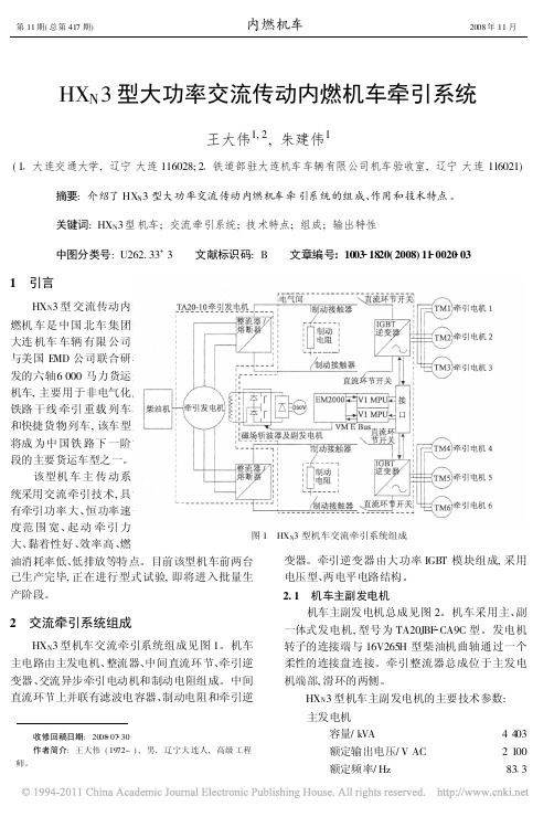
变器。牵引逆变器由大功率 IGBT 模块组成, 采用
已生产完毕, 正在进行型式试验, 即将进入批量生
电压型、两电平电路结构。
产阶段。
2 交流牵引系统组成
HXN3 型机车交流牵引系统组成见图 1。机车
2. 1 机车主副发电机 机车主副发电机总成见图 2。机车采用主、副
关键词: HXN3 型机车; 交流牵引系统; 技术特点; 组成; 输出特性
中图分类号: U262. 33+ 3 文献标识码: B 文章编号: 1003 1820( 2008) 11 0020 03
1 引言
HXN3 型 交流传动内
燃机 车是 中国 北车 集团
大连 机车 车辆 有限 公司
与美国 EMD 公司联合研
5 结论
有限元分析表明, 通过滚轮母线修形可以避免 机车柴油机供油凸轮副的边界应力集中, 大大降低 最大应力, 从而能够极大 地提高凸 轮副的疲 劳寿 命。本文对机车柴油机供油凸轮副的修形效果作 了理论分析, 以后将与有关企业进行合作, 进一步
对机车柴油机供油凸轮副进行优化设计, 并研究滚 轮修形的工艺问题。最终, 通过理论研究和工艺保 证, 提高对机车柴油机供油凸轮副的疲劳寿命。
额定功率/ kW
HART-710快速使用指南说明书
HART-710 Quick Start User Guide1. IntroductionThis manual introduces the HART-710’s basic setting and operation. The user can refer to the user manual in the ICP DAS companion CD-ROM (Path: “CD:\hart\gateway\hart-710\manual\hart-710 user manual.pdf”) for detail.The manual is intended to help users quickly understanding and easily using of HART-710. We use a HART-710 (as a HART master), one HART slave and one PC to make a simple application here, as shown in figure 1. The PC is prepared for setting and operating the HART-710.Figure 1: Application example2. Hardware configurationPin Assignment:Pin NameDescription1 HART+ Positive of HART2 HART- Negative of HART3 - N/A4 - N/A5 - N/A6 - N/A7 - N/A8 - N/A9 +VS V+ of Power Supply(+10 ~ +30 V DC ) 10 GND GND of Power Supply 11 TXD Transmit Data of RS-232 12 RXD Receive Data of RS-232 13 GND GND of RS-232 14 RX+ Receive Data+ of RS-422 15 RX- Receive Data- of RS-422 16 TX+ Transmit Data+ of RS-422 17 TX- Transmit Data- of RS-422 18 - N/A19 D+ Data+ of RS-485 20D-Data- of RS-485DIP Switch:The user can sets the DIP switch to the “Default” position for default settings.Jumper:When the pin 1&2 of JP4 is closed, 250 Ω(1/4 W) resistor will connect to HART network. By default, the pin1&2 of JP4 is closed.LED Indicator:LED Name Status Descriptionon Power supply is ok.PWRoff Power supply has failed.flash CommunicationerrorERRoff Noerrorflash Flash once about 1 s: It is at initial mode.Flash once about 500 ms: It had received the burst frame.RUNon It is at normal operationLED Name Status DescriptionoffFirmware has not loaded yetRS-232 connection:HART connection:3. Install UtilityInstall .NET Compact Frameworka. It needs the runtime environment with .NET Framework 2.0 or above to execute the utility in the PC. If there has .NET Framework 2.0 or above in the PC, this step can be omitted.b. Please setup .NET Compact Framework, the user can get the setup file from the following website.◆Microsoft .Net Framework Version 2.0:/downloads/details.aspx?FamilyID=0856eacb-4362-4b0d-8edd-aab15c5e04f5&DisplayLang=en◆Microsoft .Net Framework Version 3.5:/downloads/details.aspx?familyid=333325FD-AE52-4E35-B531-508D977D32A6&displaylang=enInstall HG_Tool.exea. Download the setup file of “HG_Tool” from the CD-ROM disk following thepath of “CD:\hart\gateway\utilities\hg_tool\” or the web site:“ftp:///pub/cd/fieldbus_cd/hart/gateway/utilities/hg_tool/”b. Execute the Setup.exe file to install the “HG_Tool” Utility.c. After finishing the installation of the HG_Tool, users can find the utility asshown in the following screen shot.4. Communication testStep 1: Connect PC, HART-710 and HART slave device according to figure1.Step 2: Turn the DIP Switch to default position.Step 3: Turn the power of the HART-710 on.Step 4: Wait the “RUN” led indicator changes into continued on. If the led isalways flash, please recheck the hardware connection. It means theHART-710 module can’t connect with HART slave device.Step 5: Open the utility (HG_Tool.exe).Step 6: Set the communication settings.When the DIP Switch is at default position, the HART-710 module will have the follow settings:a.Protocol: MB RTU ID: 1c.Baud Rate: 115200 bpsd.Data Bits: 8e.Stop Bits: 1f.Parity: NoneSo the utility must have the same settings with the HART-710 module, asshown in the below.Step 7: Click “Connect” button.Step 8: Wait the traffic light changes into “green”. If the traffic light is always “yellow”, it means the PC can’t connect to HART-710 module, pleaserecheck the RS-232 connection.Step 9: Click “Device Information”.Step 10: The user can select default command or user command and then click “Basic Operation” on the right-click menu to get the information of theHART command.Ex: The information of HART command 0 is shown in the below.。
M710e 用户指南和硬件维护手册说明书
第 3 章 计算机锁. . . . . . . . . . . . 9
锁住计算机外盖 . . . . . . . . . . . . . . 9 连接 Kensington 式钢缆锁 . . . . . . . . 10 连接钢缆锁 . . . . . . . . . . . . . . . 11
图 7. 连接钢缆锁
第 3 章 . 计 算 机 锁 11
12 M710e 用户指南和硬件维护手册
第 4 章 更换硬件
本章提供如何为您的计算机更换硬件的说明。
更换硬件之前
注意:打开计算机或尝试进行任何修理之前,请先阅读本节和《重要产品信息指南》。
更换硬件之前需要注意的事项 • 仅使用 Lenovo 提供的计算机组件。 • 安装或更换选件时,请使用本手册中列出的相应说明以及随选件附带的说明。 • 在全世界大部分地区,Lenovo 都要求退回有问题的 CRU。CRU 附带有关此事宜的信息,或将
2 M710e 用户指南和硬件维护手册
后视图
注:您的计算机型号可能与插图略有不同。
图 2. 后视图
1 音频输出接口 3 VGA 输出接口 5 USB 3.1 Gen 1 接口(2) 7 串口 9 线缆锁插槽 (2) 11 安全锁插槽 13 PCI-Express 卡区域
2 DisplayPort® 输出接口 4 USB 2.0 接口(2) 6 电源线接口 8 以太网接口 10 挂锁环 12 串口(选配)
图 1. 前视图
1 光盘驱动器弹出/关闭按钮 3 内置扬声器(选配) 5 读卡器插槽(选配) 7 电源按钮
2 光盘驱动器状态指示灯 4 存储驱动器状态指示灯 6 电源指示灯 8 麦克风接口
Rifton K710产品说明书
Support Station K710 Product ManualK710 Product Manual2© 2018 Rifton EquipmentContentsImportant information 2Safety messages 3Recommended use 4Item dimensions 5Check your order 6Installation 6Basic components7Accessories 8Operation 9Maintenance, cleaning and warranty 10Materials and user modifi cations11IMPORTANTPlease save this product manual for future reference. Additional copies areavailable at• Thoroughly read and understand the information in this product manual beforeattempting to use this product. If the procedures and instructions in this product manualare not followed, serious injury or death could occur.• A qualifi ed professional must assess the appropriateness and safety of all equipment foreach user.• This product is intended for use by clients of unreliable judgment. Adult supervision isrequired at all times.• To prevent falls and injuries:○Ensure the appropriate use of straps and supports at all times. Straps and supportsare provided for the safety of the user and must be carefully adjusted for comfort andsecurity.○Tighten all adjustment knobs before use and immediately after making anyadjustments.○Do not adjust the height of the trunk board while in use.○Do not use this product for clients outside the height and weight limits specifi ed inthis manual.○Do not use the pivot feature when the client is unable to move his or her feet.○Only use the pivot feature when the trunk board is horizontal.• To prevent structural failure, which may result in serious injury or death:○Inspect this product and accessories regularly for loose or missing screws, metalfatigue, cracks, broken welds, missing attachments, general instability or other signsof excessive wear.○Immediately remove this product from use when any condition develops that mightmake operation unsafe.○Do not use Rifton components or products for any purpose other than their intendeduse.34Figure 4a: The fi xed confi guration canbe used as a stand-alone unit with the kneeboard and padded trunk board. It enables a client to assist in sit-to-stand for clothing adjustment and hygiene care. The client may remain in the assisted upright position for a diaper change orkneeboard, the trunk board cannot pivot.Figure 4b: The pivot confi guration canbe used as a transfer aid to a stationary toilet. Without the kneeboard, the padded trunk board can pivot 180º. Installed near a standard toilet, a client can use the Support Station to assist in sit-to-stand from a wheelchair and rest their torso on the padded trunk board. Then, whilea position close to the toilet.Recommended useThe Rifton Support Station is a Class 1 medical device. It provides front-leaning support during toileting and hygiene care for children and adults with disabilities. When not in use, it folds neatly against the wall.Figure 4b5User and item dimensionsBasic dimensions: in use, and folded up with kneeboard.Height46-80 (117-203)Important: U ser height and weight must not exceed the maximum.Trunk board size24x24 (61x61)Maximum trunk board height 45 (114)Minimum trunk board height 26 (66)Max. working load lbs (kg)250 (113)Suggested layout for installation when used with pivot design.6Check your orderThe Rifton Support Station comes fully assembled. Do not dispose of packaging materials until you are completely satisfi ed that the product is installed properly and working.If your shipment is incomplete or in any way damaged on arrival, please call Customer Service,InstallationTo prevent falls and serious injury:• Make sure the bottom ends of thevertical extrusions rest weight-bearing on the fl oor.• A qualifi ed professional, such as a building contractor or maintenance person, must securely install thisproduct to the wall using the following procedure:1. Figure 6a: Remove one end cap from each horizontal crosspiece of the frame with a fl at-head screwdriver. Slide out the cover strips to access the bolt holes. Fasteners are not included. Use fasteners to suit the wall construction. Installation must be adequate to support a 250 lb.(113 kg) user.2. Fasten product securely to the wall with a minimum of two fasteners per horizontal crosspiece.3. Replace the cover strips and end caps.4. Frame must be level and perpendicular to the fl oor so that the height adjusters move and latch smoothly.5. If height adjusters do not operatesatisfactorily, contact Customer Service.Figure 6aTo prevent falls orinjury, do not adjust the height or angle of the trunk board with a client on it.The Rifton Support Station is equipped with two adjustment bars:• Figure 7a: The lower adjustment bar sets the height of the trunk board (A).• Figure 7a: The upper adjustment bar sets the angle of the trunk board (B).• Figure 7b: The adjustment bars canbe worked from either side. Grasp the handle (C) from one side only, lift the handle, and squeeze the trigger (D) while using your other hand to lift on the front edge of the trunk board as shown in fi gure 7a. The built-in safety stop will prevent you from squeezing the triggerwhile the trunk board is bearing weight.• Move the adjustment bar to the desired position and release the trigger, allowing the trigger to engage into the nearest position.• Figure 7b: The height of the trunk board from the fl oor is indicated on the inside of the frame (E), referenced from the top edge of the lower adjustment bar.• The trunk board may be folded against the wall while not in use. To do this, set the lower adjustment bar to less than 37", then raise the upper adjustment bar to its maximum. If the kneeboard is not attached, make sure the pivot latch is rotated to center before collapsing the trunk board.Figure 7aABFigure 7bCDEBasic item78Figure 8aFigure 8bPivot Confi gurationFigure 8a: The trunk board can rotate tofacilitate transfers to a stationary toilet. This feature does not function with the kneeboard attached. The trunk board must be horizontal before using the pivoting feature.Figure 8a: The rotation of the trunk boardcan be set in 15˚ increments using the pivot latch. Press down on the pivot latch handle (A) fi rmly while rotating the trunk board. Release the latch and allow it to engage into the nearest position. The trunk board can be rotated 180 degrees.Removal of kneeboardFigure 8b: To remove the kneeboard,pull out the four quick-release pins (B) underneath the trunk board. To install the kneeboard, line up the braces and insert the pins.AccessoriesHandholdsFigure 8c: The handholds can be securedin the slots of the trunk board for users who require a vertical hold. To attach the handhold, remove the nut from the bottom and assemble it again through the slot in the trunk board.Support strapTo avoid falls or injury, adult supervision isrequired at all times. The support strap is not a substitute for close caregiver supervision.Figures 8d and 8c: The support strap (C)can be secured around the user’s trunk to help maintain position on the trunk board. To attach the strap on the trunk board, fasten the short straps (D) around the edge of the trunk board and through the hand slot.BFigure 8cFigure 8dFigure 8eCD9Figure 9a. The user approaching the trunk boardand reaching out for the handholds.Figure 9b. The user in the raised position.Operation• Adjust the trunk board to theappropriate height and angle for the user. The recommended height is just below the hips of the user.• Figure 9a: Wheel the client to the Support Station facing the padded concave trunk board.• With the handholds or slots the user can assist, pulling up or forward, or can be helped up onto the trunk board to support the upper body.• Secure the support strap if needed (see Page 8).• The cutouts on the sides of the trunk board may be used for additional support for the elbows.• While the user is positioned securely on the trunk board, the caregiver can complete necessary care and clothing adjustments.Fixed confi gurationFigure 9b: When the user is securelypositioned with the upper body supported by the trunk board, the wheelchair can be removed and replaced by a portable toilet.Pivot confi gurationSecurely position client on the trunk board. Pivot the user and trunk board to enable access to the fi xed toilet. The client must have enough leg control to move their feet during pivot.MaintenanceThis product is designed and tested for an expected life of 5 years when used andmaintained in accordance with this manual. At all times, users must ensure that theproduct remains in a safe and useable condition, including regular maintenance andinspections as specifi ed in the manual.To prevent structural failure, which may result in serious injury or death:• Inspect this product and accessories regularly for loose or missing screws, metalfatigue, cracks, broken welds, missing attachments, general instability or other signs ofexcessive wear.• Immediately remove this product from use when any condition develops that mightmake operation unsafe.• Do not use Rifton components or products for any purpose other than their intendeduse.• Replace or repair components or products that are damaged or appear to be unstable.• Use only Rifton authorized replacement parts. Order information for replacement partsis provided on the back of this product manual.CleaningAs needed, clean with disinfectant wipes or a solution of up to 10% bleach. Do not useexcessive amounts of water. Do not use pine oil cleaners.Warranty StatementIf a Rifton product breaks or fails in service during the fi rst year, we will replace itfree of charge.10Materials• Steel hardware items (nuts, bolts, screws, etc) are typically zinc or nickel plated, orstainless steel.• Upholstery items (pads, support blocks, padded prompts, etc) are typically polyurethanefoam with a fi re-retardant cover made from expanded vinyl.• Frames are typically steel or aluminum tubing, welded together, and coated with abaked-on paint fi nish. Some frame components may also be stainless steel.• Straps are typically made of polypropylene or nylon webbing.• Plastic components are typically injection molded from a variety of industrial resins.All materials are latex, lead and phthalates free.User modifi cationsproducts or components, or use Rifton products or componentsin conjunction with products from other manufacturers. Rifton does not acceptresponsibility for any modifi cations or alterations made to our components or productsafter they leave our premises. Customers modifying or altering our components orproducts, or using them in conjunction with products from other manufacturers, do soat their own risk.11。
MEAN WELL NPB-1200系列超宽输出范围智能电池充电器产品说明书
All rights reserved by MEAN WELL 2021Ultra-Wide Output Range Intelligent Battery ChargerNPB-1200SeriesFrank Chen|Product Manger|Product Strategy Center******************WattPB/NPB Series RoadmapO l d G e n e r a t i o nN e w G e n e r a t i o n120 240 360 500750 1000 12001500 1700PB-120 / 230 / 300 / 360 / 600 / 1000NPB-120 / 240 / 360 / 450 / 750 / 1200/ 1700Stationary Type-Compact size programmable chargerNPBSeries Selection TableSeriesWattageAC Input VoltageDC Output VoltageBuilt-in DC FanOutput ConnectorDimension (mm)NPB-120120W 90~264Vac14.4Vdc 28.8Vdc57.6Vdc 96Vdc (450W)Terminal Block Anderson 4 pin XLR180*96*49NPB-240240W NPB-360360W NPB-450450W Terminal Block205*130*55NPB-750750W 230*158*67NPB-12001200W 250*158*67NPB-17001700W300*184*673 Key Features of NPBSeriesSmartFunctionAuto rangingRemote controlFast Charging&High Efficiency upto 93%Global certification3 years warrantySafe &DurableHighEfficiencyKey Features●Patented auto ranging with ultra-wide charging voltage(10.5~21V, 21~42V, 42~80V)●Built-in CANBus protocol for control, setting and monitoring●Programmable 2/3 stage and charging curve settings via SBP-001●Manual setting for 2/3 stage and 4 built-in charging curves via DIP switch ●Adjust charging current between 50~100% via VR on front panel●Over temperature automatic de-rating●Thermal controlled DC fan for noise reduction●Temperature compensation function to prolong battery life●Multiple protections: Short circuit / Over voltage / Over temperature /Battery under voltage / Battery reverse polarity (no damage)●Suitable for lead-acid (Pb) and li-ion batteries●Carry handle accessory available (Order No.: DS-Carry handle)●Safety: CB, UL, DEKRA, EAC, CE, UKCA(62368-1 + 60335-1/-2-29)●3-year warrantyNew Gen.Reduced Size(%)Series Dimension(LxWxH)NPB-1200250*158*67 mm-32%Old Gen.Series Dimension(LxWxH)PB-1000300*184*70 mmOld Gen. —PB SeriesNew Gen. —NPB SeriesSize MiniaturizationComparison TableOld Gen. -PB-1000SeriesOutput Power1000W1200WInput Voltage90~264Vac90~264VacCharging Voltage14.4V (stationary voltage)28.8V (stationary voltage)57.6V (stationary voltage)14.4V( 10.5~15.2V)28.8V( 21~30.4V)57.6V ( 42~60.8V)(Patent number.: CN111711254B )Patented AutoRangingAdjustable ChargingAdjust between 50~100% via VR on frontpanel or connect with computerCommunicationInterface(Built-in )Charging Stage2/3/8stage 2 or 3 stage selectable by DIP S.W or connect with PC Other Function Floating maintenance, NTC sensing , RC Floating maintenance, NTC sensing , RCEfficiency85~89% 92~94%Working Temp.-20~+60℃-30~+70℃Multi-intelligentProtectionsShort circuit / Over voltage / Over temp. /Battery reverse polarityShort circuit/ Over voltage/ Over temp./ Battery reversepolarity/ Battery static discharge protection Applicable Battery Lead-acid battery lead-acid or li-ion batteriesSafety Approvals62368-1or60335-2-29 (by series)62368-1+60335-2-29dual certificationNew Gen.-NPB-1200 SeriesAuto Ranging Charging with Multiple Functions21V 42V 80V 100V10.5V 21V 42V 54VUltra-wide charging voltage ,and can be used for a wide range of batteriesBuilt-in CANBus Protocol InterfaceWith CANBus protocol,control and monitoring function can be realized.It is helpful when users intend to modify the parameters ers can access the master and modify the parameters through CANBus,which include,ON/OFF,output voltage/current,temperature.More to that,users can even change the charging curve parameters,such as constant current level,boost voltage,float voltage and timeout function.Simple Operation InterfaceProgrammer SBP-001 is able to work with:ENC-120/240/360、HEP-1000C 、RCB/RPB-1600、DBU/DBR-3200、NPB-450/750/1200/1700 seriesSmart Programmer SBP-001Charger can be quickly connected with USB to the laptopConnectionFunction Settingcurveadjustable2 or 3-stageselectableChargingtimeout setting Programmer SBP-001 is able to work with:ENC-120/240/360、HEP-1000C、RCB/RPB-1600、DBU/DBR-3200、NPB-450/750/1200/1700 seriesLead-acid BatteriesLi-ion Batteries14.4V 、28.8V 、57.6V 、67.2V 、72V 、84V 、96V 、120V 13.8V 、27.6V 、55.2V•Wet cells •Gel cells •AGMFor A Variety of Batteries•Ternary lithium•Lithium-ion manganese oxide (LiMn 2O 4)•Lithium iron phosphate (LiFePo 4)•Electric crane •Forklift truck •Automated guided vehicle •DroneApplications•Electric drill •Electric weeder •Electric screwdriver/ Impact wrench •Electric blenderElectric Mobility•Electric motorcycle •E-Bikes •Golf cart •E-Scooters •Electric unicycleHand-held Power ToolsHandling EquipmentMobile Robotics Charging Stations•Hospital food delivery robot •Airport guide robot •Warehouse picking robot。
- 1、下载文档前请自行甄别文档内容的完整性,平台不提供额外的编辑、内容补充、找答案等附加服务。
- 2、"仅部分预览"的文档,不可在线预览部分如存在完整性等问题,可反馈申请退款(可完整预览的文档不适用该条件!)。
- 3、如文档侵犯您的权益,请联系客服反馈,我们会尽快为您处理(人工客服工作时间:9:00-18:30)。
downloaded from the PDF Library by steve@barringtondieselclub.co.za on 01-Mar-11
downloaded from the PDF Library by steve@barringtondieselclub.co.za on 01-Mar-11
downloaded from the PDF Library by steve@barringtondieselclub.co.za on 01-Mar-11
downloaded from the PDF Library by steve@barringtondieselclub.co.za on 01-Mar-11
downloaded from the PDF Library by steve@barringtondieselclub.co.za on 01-Mar-11
downloaded from the PDF Library by steve@barringtondieselclub.co.za on 01-Mar-11
downloaded from the PDF Library by steve@barringtondieselclub.co.za on 01-Mar-11
downloaded from the PDF Library by steve@barringtondieselclub.co.za on 01-Mar-11
downloaded from the PDF Library by steve@barringtondieselclub.co.za on 01-Mar-11
downloaded from the PDF Library by steve@barringtondieselclub.co.za on 01-Mar-11
downloaded from the PDF Library by steve@barringtondieselclub.co.za on 01-Mar-11
downloaded from the PDF Library by steve@barringtondieselclub.co.za on 01-Mar-11
downloaded from the PDF Library by steve@barringtondieselclub.co.za on 01-Mar-11
downloaded from the PDF Library by steve@barringtondieselclub.co.za on 01-Mar-11
downly steve@barringtondieselclub.co.za on 01-Mar-11
downloaded from the PDF Library by steve@barringtondieselclub.co.za on 01-Mar-11
downloaded from the PDF Library by steve@barringtondieselclub.co.za on 01-Mar-11
downloaded from the PDF Library by steve@barringtondieselclub.co.za on 01-Mar-11
downloaded from the PDF Library by steve@barringtondieselclub.co.za on 01-Mar-11
downloaded from the PDF Library by steve@barringtondieselclub.co.za on 01-Mar-11
downloaded from the PDF Library by steve@barringtondieselclub.co.za on 01-Mar-11
downloaded from the PDF Library by steve@barringtondieselclub.co.za on 01-Mar-11
downloaded from the PDF Library by steve@barringtondieselclub.co.za on 01-Mar-11
downloaded from the PDF Library by steve@barringtondieselclub.co.za on 01-Mar-11
downloaded from the PDF Library by steve@barringtondieselclub.co.za on 01-Mar-11
downloaded from the PDF Library by steve@barringtondieselclub.co.za on 01-Mar-11
downloaded from the PDF Library by steve@barringtondieselclub.co.za on 01-Mar-11
downloaded from the PDF Library by steve@barringtondieselclub.co.za on 01-Mar-11
downloaded from the PDF Library by steve@barringtondieselclub.co.za on 01-Mar-11
downloaded from the PDF Library by steve@barringtondieselclub.co.za on 01-Mar-11
downloaded from the PDF Library by steve@barringtondieselclub.co.za on 01-Mar-11
downloaded from the PDF Library by steve@barringtondieselclub.co.za on 01-Mar-11
downloaded from the PDF Library by steve@barringtondieselclub.co.za on 01-Mar-11
downloaded from the PDF Library by steve@barringtondieselclub.co.za on 01-Mar-11
downloaded from the PDF Library by steve@barringtondieselclub.co.za on 01-Mar-11
downloaded from the PDF Library by steve@barringtondieselclub.co.za on 01-Mar-11
downloaded from the PDF Library by steve@barringtondieselclub.co.za on 01-Mar-11
downloaded from the PDF Library by steve@barringtondieselclub.co.za on 01-Mar-11
downloaded from the PDF Library by steve@barringtondieselclub.co.za on 01-Mar-11
downloaded from the PDF Library by steve@barringtondieselclub.co.za on 01-Mar-11
downloaded from the PDF Library by steve@barringtondieselclub.co.za on 01-Mar-11
downloaded from the PDF Library by steve@barringtondieselclub.co.za on 01-Mar-11
downloaded from the PDF Library by steve@barringtondieselclub.co.za on 01-Mar-11
downloaded from the PDF Library by steve@barringtondieselclub.co.za on 01-Mar-11
downloaded from the PDF Library by steve@barringtondieselclub.co.za on 01-Mar-11
downloaded from the PDF Library by steve@barringtondieselclub.co.za on 01-Mar-11
downloaded from the PDF Library by steve@barringtondieselclub.co.za on 01-Mar-11
downloaded from the PDF Library by steve@barringtondieselclub.co.za on 01-Mar-11
downloaded from the PDF Library by steve@barringtondieselclub.co.za on 01-Mar-11
downloaded from the PDF Library by steve@barringtondieselclub.co.za on 01-Mar-11
downloaded from the PDF Library by steve@barringtondieselclub.co.za on 01-Mar-11
downloaded from the PDF Library by steve@barringtondieselclub.co.za on 01-Mar-11