Skelion使用手册_en_06_27_2012
红狮红外热成像系列产品说明书

RAM ® 6000 Cellular RTUsSixnet Networking SeriesPRODUCT HIGHLIGHTS>High-performance 4G LTE cellular connectivity >Natively supports Modbus and DNP3 protoocols >Multiple communication ports >Routing capabilities provide secure, reliable communicationRed Lion’s Sixnet series RAM 6000 industrial cellular RTUs with 4G LTE provide a rugged, reliable solution for monitoring and controlling remote assets and processes in extreme conditions.RAM 6000 RTUs seamlessly connect Modbus or DNP3 enabled SCADA equipment with master station or control center servers utilizing secure cellular 4G LTE or 3G wireless networks. A built-in I/O concentrator allows the RAM 6000 to collect local sensor data and optimize the cellular bandwidth by optionally reporting only on an exception. Ideal for deployment in industrial M2M networks such as oil and gas, water/wastewater, utility, transportation and mining applications, our industrial cellular RTUs provide a reliable network extension to remote locations. The end result helps customers save wiring time, space and cost by combining separate functions into one cellular device.APPLICATIONS >Oil & Gas >Water/Wastewater >Utility >Transportation >MiningCUSU LLISTEDcompliantFEATURES & BENEFITS >Multiple Communication Ports• O ne RS232 serial port, and up to five Ethernet ports provide seamless connectivity to remote devices >Rugged, High-Performance Design • Reliable operation in rugged environments • -40° to 75°C operating temperature* >Modbus and DNP3 Support• E asily communicates with SCADA equipment with native protocols>Out-Of Band Management (OOBM) • S ecure remote CLI access via RS232 port • P re-loaded with many console port configurations >Secure Ethernet Connectivity• R outing capabilities for reliable communication • S tateful firewall, SSL, GRE and VPN services and packet inspection reduce the risk of unwanted access >Easy Configuration Options• S treamlined web-browser interfaceWIRELESS INTERFACEAT&T LTE with fall back to HSPA+Bell Mobility LTE with fall back to HSPA+Generic LTE with fall back to HSPA+Manitoba LTE with fall back to HSPA+Rogers LTE with fall back to HSPA+Sprint EVDO Rev. A with fall back to 1xRTTTELUS LTE with fall back to HSPA+Verizon LTE with fall back to EVDODual-band CDMA2000 EVDO Rev. A(backward compatible with 1xRTT)GSM/HSPA+ (backward compatible with EDGE) PROGRAMMABLE PLATFORMSoftware Development Kit (SDK)C/C++/PerlPROTOCOL GATEWAYI/O controllerModbus RTU/TCP/ASCIIDNP3 – slaveSYSTEM PERFORMANCE32-bit ARM9 400 MHz CPU512 MB NAND128 MB RAMTUNNELINGIPsec, GRE, OpenVPNIPNAT, port forwarding, dynamic DNS, DHCPStateful inspection firewall, IP transparency ETHERNET INTERFACE (10/100 AUTO-SENSING) 1x or 5x RJ45WAN capability on 5th portSERIAL INTERFACE1x RS232 serial DB9 115200bpsUSB INTERFACE1x USB 2.0 device miniINPUTS & OUTPUTS1x digital/analog inputs1x digital output (open-collector)POWER INPUTRange: 8-30 VDC (12 or 24 VDC nominal)Standby: 1.4W - 3.3W (typical)Transmitting:6401: 2.0W – 5.0W6421: 3.4W – 6.4W660x: 2.0W – 2.9W6621: 3.6W – 4.5W680x: 2.6W – 5.0W6821: 4.2W – 6.6W670x: 2.6W – 6.9W6721: 4.3W – 8.7WHeat dissipation: 30 BTU/hour maxMECHANICALRAM-6x0xDimensions: 120 x 96 x 32 mm (4.7” x 3.77” x 1.25”)Weight: 453g (1 lb)RAM-6x21Dimensions:120 x 96 x 51 mm (4.7” x 3.77” x 2.0”)Weight: 500g (1.1 lbs)ENVIRONMENTALOperating temperature: -40° to +75°C*Shock: IEC60068-2-27Vibration: IEC60068-2-6Humidity: 5 to 95% non-condensingCERTIFICATIONEMI/EMC:Emissions: FCC, Part 15 and Industry Canada, ICES-003; Class A;EN55022, IEC61000-6-4Immunity: IEC61000-6-2 (EN61000-4-2,3,4,5,6,8)Hazardous locations: Class I, Div. 2, Groups A, B, C, D, ISA 12.12.01 Electrical safety: UL508/CSA22.2/14 (CUL); IEC61010-1Carrier specific approvalsRoHS compliantWARRANTY3 years on design and manufacturing defects* S ee Hardware Manual for thermal considerations.DIMENSIONSin inches (mm)ORDER GUIDE* See Band/Frequency table for compatability FREQUENCY SPECIFICATIONSConnect. Monitor. Control.。
VuLink CI In-Situ 设备用户指南说明书
Manual de usoÍndice de contenidosSímbolos (3)Información de seguridad (4)Componentes necesarios (5)Cable (5)Instrumento (5)Software (5)Pilas (5)Accesorios (6)Cómo funciona (7)Ajustes de Vulink (9)Retire la lengüeta de las pilas y presione el botón (9)Solución de problemas de conectividad de red (9)Añada otro instrumento y presione el botón (opcional). (10)Entender los LEDs (10)Registro con VuLink (12)Registros de VuLink (12)Registros de instrumentos (12)Uso de HydroVu (13)Uso de VuLink con VuSitu (14)Creación de alarmas (15)Uso de VuLink con un servidor FTP (16)Conexión de un instrumento de pulso a VuLink (18)Configuración de un instrumento de pulso con VuSitu (19)Añadir el instrumento a VuLink. (19)Configúrelo. (19)Entender las tarjetas SIM de VuLink (21)Actualización de VuLink (21)Controles (22)Especificaciones (23)Símbolos importantes en este manualSímbolos importantes en el productoEste símbolo indica información crítica de seguridad. Ignorar el texto que acompaña a este símbolo puedeprovocar lesiones o la muerte debido a una manipulación inadecuada.De acuerdo con la Directiva de Residuos de Aparatos Eléctricos y Electrónicos de la UE de 2005 y otras directivas posteriores, VuLink no debe desecharse junto con la basura doméstica convencional. Compruebe la normativa local sobre residuos electrónicos/eléctricos antes de deshacerse de un dispositivo VuLink.Directiva RAEE: Eliminación de VuLink al final de su vida útil PrecauciónUtilización correcta de VuLinkInstalación y sustitución de las pilasInstalación de la antena1 Cable2 Instrumento3 Software4 PilasCable robusto con sistema Twist-Lock Aqua TROLLVea los datos, gestione losinstrumentos, cree alarmas ymodifique la configuración deVuLink desde su navegador.Comuníquese con VuLink desde cualquierdispositivo móvil con Bluetooth y con laaplicación móvil VuSitu.Baro TROLLSoftware deHydroVuAplicación móvil VuSituNivel TROLL Rugged TROLLConecte VuLink con un instrumento Aqua TROLL, Baro TROLL,Level TROLL o Rugged TROLL.Con o sin ventilación.Antena de telefonía móvilDivisor de cables RuggedAdaptador universal decargaKit de montajeReferencia: 0043630Referencia: 0095500 (con ventilación)Referencia: 0085840 (sin ventilación)Referencia: 0101000Referencia: 0095570La antena de telefonía móvil permite una fuerte conectividad a la red móvil.Con el divisor de cable Rugged, puede conectar hasta 8 instrumentos con VuLink.Para acoplar instrumentos de medición de flujo y dispositivos que no disponene de un conector Twist-Lock, utilice el adaptador universal de carga.El kit de montaje permite fijar VuLink a un poste, una pared u otra estructura.123MosquetónDispositivo de telemetría VuLinkInstrumentoVuLink cuelga de la parte superior de un pozo con su mosquetón desmontable.VuLink aporta energía a los instrumentos de monitorización, transmite los datos a la nube y le notifica cuando es necesario realizar algún mantenimiento.Un instrumento de In-Situ mide la calidad y/o el nivel del agua.Coloque la antena y conecte un instrumento.Después de conectar la antena externa o de a bordo y elinstrumento, siga las instrucciones de las siguientes páginas deesta guía de inicio rápido.24telemetría.Visite la página y cree una cuenta.Haga clic en el enlace de la página de telemetría en el menú a la izquierda de la página. A continuación, haga clic en Añadir un VuLink .Abra su cámara web y escanee el código QR en su dispositivo, o escriba el código de registro en el campo disponible.o c l i cPulse en 2G para modificar la configuración de red deVuLink. Pulse enGuardar .VuLink debería ahora ser capaz de conectarse a una red y sincronizarse con HydroVu.Presione el botón Todos los ajustes en la parte inferior dela pantalla.Pulse en Red móvil en lapantalla de Ajustes.Retire la tapa de las pilas girándola en sentido antihorario y tirando hacia abajo.Asegúrese de que la antena está bien colocada antes de continuar.Presione el botón. Todos los LEDs se encienden. A continuación, cada LED cambia de color en función del estado del dispositivo.Retire la lengüeta amarilla para permitir que la corriente pase a través de las pilas. Vuelva a colocar la tapa.VuLink funciona con los instrumentos Aqua TROLL, Level TROLL, Baro TROLL y Rugged TROLL. Siga los siguientes pasos para comenzar a transmitir datos.5 Retire la lengüeta de las pilas y presione el botón.Solución de problemas de conectividad de redVuLink se conecta al nuevo instrumento y a la red de datos.Desconecte el instrumento de VuLink. Añada otro. Presione el botón.VuLink se conecta a HydroVu o a un servidor FTP .Todos los LEDs indican el estado actual del dispositivo. Consulte la sección siguientepara obtener más detalles.Entender los LEDsRojo fijo Verde fijoVerde intermitenteRojo intermitente La carga de la batería es de al menos el 75%.La carga de la batería entre el 25% y el 50%.La carga de la batería está entre el 50% y el 75%.La carga de la batería inferior al 25%.Estado de la batería7 Añada otro instrumento y presione el botón (opcional).Parpadeo rojo y verdeUn LED rojo y verde intermitente indica un problema con las pilas. No haga uso de VuLink en estas condiciones. Compruebe las pilas y vuelva a colocarlas si es necesario.Rojo fijoVerde fijoVerde intermitenteRojo intermitenteBuscando un instrumentoNuevo instrumento no encontradoConectado al instrumentoNo hay instrumentos conectados a VuLinkRojo fijoRojo intermitenteVerde fijoVerde intermitenteIntentando conectarse a la redConectado a la redNo se puede conectar a la redLa antena de VuLink está desconectada o VuLink no puede localizar una red móvil.Rojo fijoVerde fijoAzul fijoAzul intermitenteVerde intermitenteRojo intermitenteDispositivo no reclamadoCarga exitosaConectado por BluetoothListo para conectarConectando y cargando datos a HydroVuFallo en la conexión con Estado de la conexión del instrumentoEstado de la conexión a la redEstado de la conexión con la nubeEstado de la conexión BluetoothProgramar un reg-istro en VuLink conla aplicación móvil VuSitu.un registroen el instru-con VuSitu.archivos de registro con Registros de VuLinkRegistros de instrumentos112Ver sus datos en HydroVu.Crear y editar paneles de controlGestionar alarmasConfigurar notificacionesVer ubicacionesConfigurar dispositivos detelemetríaCargar datosEditar parámetros calculadosGestionar usuariosVer sus datosOpciones del menú de la barra lateral/Páginas de HydroVuPantalla del dispositivo de telemetría conectadoPulse en la opciónConfiguración del menú y luego elija Alarmas en tiempo real .Para crear una alarma, pulse en Añadir una alarma entiempo real.Seleccione el parámetro que debe activar la alarma y establezca los límites.Conéctese a VuLink con laaplicación móvil VuSitu.Introduzca sus credenciales FTP . A continuación, pulse en Probar y Guardar .VuLink prueba la conexión con el aplicación muestra los resultados de la prueba.Pulse en Todos los ajustes .Seleccione el Servicio de telemetría en la nube .a bdgPulse en el botón de radio junto a FTP .cefPuede configurar VuLink para cargar los datos en un servidor FTP a través de VuSitu. Tenga preparado el nombre del servidor FTP Recuperación de datosAcceda a la pantalla del Servicio de telemetría en la nube como se muestra arriba.Introduzca una fecha y hora de inicio, o un número de registro de inicio.Pulse en Inicio .Pulse en Cargar datos faltantes .Lea el mensaje emergente sobre los gastos de datos. Pulse en Enviar datos si desea continuar.Si la carga se produce con éxito, VuSitu muestra unaconfirmación.Componentes necesariosCableado con el adaptador universal de carga (LBUA)• Cable Rugged con bloqueo Twist-Lock con un extremo pelado y estañado • Adaptador universal de carga (LBUA)• Cable (del LBUA al instrumento de pulso)• Instrumento de pulso • VuLinkLeyenda del cable RuggedColor del cableSeñal Marrón Salida del pulsoNegro TierraRojo Alimentación (opcional)Azul Sin usar Verde Sin usarBlancoSin usarConecte el extremo con el Twist-Lock de un cable Rugged a VuLink.Conecte los hilos marrón y negro del otro extremo del cable Rugged al adaptador universal de carga.Corte los cuatro cables sin uso. Pase los cables desde el otroextremo del LBUA hasta elinstrumento de pulso.A VuLinkHasta el pulso instrumentoAñadir el instrumento a VuLink.Configúrelo.Inicie VuSitu y conéctese a VuLink.Conecte el instrumento a VuLink con un cable. Presione en el botón Añadirde VuSitu.VuSitu muestra un mensaje de confirmación. Pulse en OK paradescartarlo.Pulse en el menúdesplegablede InstrumentosConectados .Pulse en el menúdesplegablede Instrumentos Conectados .Pulse en Añadir nuevo .Seleccione el botón de radio del instrumento medidor de pulso .Pulse en el instrumento.Seleccione la frecuencia baja o alta.Frecuencia baja: Elija uno de los tres parámetros integrados o cree un parámetro personalizado.Añada pluviómetros y otros dispositivos de pulso a VuLink con la configuración de pulso de VuSitu.engranaje junto al campo dela unidad para seleccionar unaIntroduzca un valor mínimo ymáximo.Introduzca una frecuenciamínima y máxima en hercios.Pulse enGuardarparaconfirmar la configuracióndel instrumento medidor deIntroduzca el valor de un pulsoen las unidades seleccionadas.Pulse en Guardar. VuSitumuestra el mensaje de"Guardando".VuSitu muestra el mensaje de"Guardando".Alta frecuencia: SeleccioneAlta Frecuencia y elija unparámetro y una unidad.Tarjeta SIM externaSIM integradaVuLink trata de utilizar una tarjeta SIM externa para todas las comunicaciones si hay una. Si la comunicación a través de la SIM externa falla, VuLink utiliza en su lugar la tarjeta SIM integrada.Si no hay una tarjeta SIM externa, VuLink utiliza su SIM integrada para todas las comunicaciones.21Mosquetón 2Estado de la conexión Bluetooth 3Estado de la batería 4Estado de la conexión 5Estado de la conexión a la red 6Estado de la conexión con la nube 7Antena 8 Botón de encendido 3Pilas Compatible con 3 x celdas D (1,5V - 3,6V) alcalina/Li-SOCl2 [cloruro de litio y tionilo]/Li-MnO2 [dióxido de litio y manganeso]Tiempo de funcionamiento(informe de 24 horas,batería de Li-MnO2)Hasta 12 años*.Tiempo de funcionamiento(informe de 24 horas,batería alcalina)Hasta 3 años*Precisión del reloj Menos de 1 minuto de desviación al año con capacidad de sincronización con la horafacilitada por la red para una precisión de +/- 1 segundoTipo de red4G LTE Categoría M1 (LTE-M) / NB-IoT (Narrowband) con opción a 2GBandas de radio LTE Global - B1(2100), B2(1900), B3(1800), B4(AWS 1700), B5(850), B8(900), B12(700),B13(700), B18(800), B19(800), B20(800), B28(700)Protocolos HTTPS (HydroVu), SMS (alarmas)Proveedor de datos Itinerancia global gratuita** integrada (consulte el anexo de la lista de redes para obtener más detalles: /VuLinkNetworks), ranura adicional de 4FF para soporte de SIM de tercerosAntena Conector SMA-MGPS Precisión de hasta 3 m, antena incorporadaFormato de archivo (sinHydroVu)CSVConfiguración remota CompatibleLongitud total19.1”Diámetro 1.85”Peso2,2 libras/1,0 kg (con pilas alcalinas y mosquetón incluidos, sin incluir la antena)Materiales Ryton (carcasa), PVC (tapa de las pilas), titanio (conector Twistlock, cáncamo), acero inoxidable 316 (mosquetón), silicona (tapa del teclado), latón (conector de antena SMA), policarbonato (etiqueta), Viton (juntas tóricas)Temperatura dealmacenamiento-20°C a 60°CTemperatura defuncionamiento-20°C a 50°C (Li-SOCl2/Li-MnO2), 5°C - 40°C (Alcalina)Protección contra lapenetración Dispositivo: IP68 Sistema: Hasta IP68 según especificación de la antenaProtocolos Modbus sobre RS-485, SDI-12, Pulso de baja/alta frecuencia (máximo 40 khz)Conectores 1 "Twistlock" In-Situ (admite varios instrumentos a través de un divisor de cable Rugged,TROLL Net Hub o un adaptador universal de carga)Conexiones simultáneas Hasta 8 instrumentos (máximo total de 75mA dispuestos a los instrumentos conectados a16V)Ventilación Incorporada en todos los modelos, no requiere desecanteCompensaciónbarométrica Incorporada en todos los modelos para la compensación automática de las lecturas de nivel Precisión del barómetro+/- 1 hPaAlarmas Configurables en función de las lecturas de los instrumentos y de los parámetros deldispositivoBotón de encendido Máximo total de 75mA dispuestos entre los instrumentos conectados a 16V (destinadosnormalmente a alimentar un solo instrumento)Configuración inalámbrica Compatible con Bluetooth Low EnergyTasa de registro De 1 minuto a 7 díasTasa de transmisión De 5 minutos a 7 díasMemoria512 MB (soldados a la placa de circuito)Potencia máxima de salidadel transmisor Todas las bandas LTE FDD: +23 dBm +/- 1dB (conducido)GSM900: +32,5 dBm +/- 1dB GSM1800: +29,5 dBm +/- 1dB (conducido) EGPRS900: +27,0 dBm +/- 1dB EDGE1800: +26,0 dBm +/- 1dB (conducido) Bluetooth: +5,5 dBm +/- 0,35 dB (EIRP)。
亚特兰蒂斯·克彭高速紧固工具说明书

High-speed tightening – with low reaction toolsWhat is important in your tightening processes?Atlas Copco's low reaction tools close to eliminate the reaction force in assembly applications, delivering high-speed quality tightening while taking great care of the operator.Atlas Copco’s line-up of battery powered low reaction tools are designed to improve operator ergonomics. Not only will you increase productivity and optimize your factory up-time, you will also have less costs and time lost on operator injuries and fatigue.Choosing the right tool is the first – and most important – step towards a perfect operation. Regardless of which tool within our LRT range you choose, you will have a well balanced high quality tool. And choosing the right one will make the whole world of a difference.If you need a small and reliable workhorse that promises accuracy and speed, the pneumatic ErgoPulse PTI is an excellent solution.For maximum flexibility, high torque and the lowest vibration on the market – a cordless and powerful Atlas Copco TBP Pulse Tool is your choice.For reliable and accurate low reaction tightenings with lower torque, the cordless Tensor SRB offers an error-proof production.ErgoPulse PTI – your productive workhorseThe pneumatic, low weight ErgoPulse PTI is an excellent addition to the Atlas Copco LRT line-up. Increasing tool uptime with up to five times longer service intervals.With a durable and robust design the ErgoPulse PTI is faster and more accurate than ever and will improve the production quality and throughput. The ergonomic design of the tool takes care of your operators wellbeing, all while lowering the Total Cost of Ownership of your pulse tools. With fewer tool installations you can also enjoy lower set-up costs.The ErgoPulse PTI reduces the need formaintenance and is a proven and importantpart of this fleet. Our DuraPulse® technologymeans longer time between services with upto 5 x longer service intervals. With the rightstartup and maintenance you will have optimalperformance throughout the lifetime of the tool.With Torque Boost® the torque build-up is even faster, giving you reduced hoursper production unit. Quality is improved with a more robust and stable shut-offmechanism that increases accuracy and lowers the mean shift.Faster productionwith improved qualityQuality critical tightening and high productivity with the TBP-SThe all new cordless and slender TBP-S for one-handed operations, will ensure that your joint is tightened properly and trace the job done. Perfect for a reliable and quality critical tightening.With the same hardware as the TBP but with aslimmer software version suited for quality criticaltightenings, the TBP-S battery pulse tool is a robustyet slender solution for the middle segment. With amix of productivity, ergonomics and error-proofingthe TBP-S is proven to offer less maintenance andless down-time in production.Our DuraPulse® technology – also featured in theTBP – will ensure a robustness making the TBP-S areliable pulse tool that keeps on delivering.Low vibration and long service intervalsJust like the TBP, the TBP-S shows the lowestvibration levels in the market. This means operatorcomfort and safety, reducing work related costscaused by fatigue and injuries.The patented technology and design gives youlonger service intervals than with traditional pulsetools. With TorqueBoost®, the TBP-S has activecooling and advanced motor steering, so thetorque build up is fast and gives reduced hours perproduction unit.If you need morefunctionality in yourTBP-S you can easilyupgrade it to a fullyfunctional TBP withour upgrade kit.Future ProofSafety critical tightening and full traceability with the TBPSince launch, the TBP has been redefining what a low reaction pulse tool can do. Enjoy the benefits of a cordless tool for one-handed operations, enabling error-proof production.The Atlas Copco TBP is a reliable and powerful pulsetool, offering high torque tightening with very littlereaction. Giving you speed, accuracy, traceabilityand flexibility – with cordless freedom. With a TBPyou will have direct and accurate feedback of thejoint behavior.Anything is possible. Bring Error-Proofing to thenext level with our Barcode reader (EHMI) and alocation system like the ILT. Customize your toolwith accessories to fit your specific needs.Thanks to the patented technology and design,you will have longer service intervals than witha traditional pulse tools. Reduced oil leakage,separation of air and oil, and a cooler tool –meaning higher performance and uptime.Offering better protectionBV from injuries andincreasing the lifespan of your tools, results in hugesavings.Error-proof production with the cordless Tensor SRBThe Atlas Copco Tensor SRB delivers multipletightening technologies with accuracy, traceability, flexibility – and low reaction. It offers both traditional strategies like 2 steps and Quick Step, but also more advanced strategies such as TurboTight and TensorPulse. With a slim design it allows for easy access in cramped spaces.The Tensor SRB has low weight and great balance – with a slim design – ergonomically designed to prevent operator fatigue. New electronics and an improved motor will boost your productivity. Choose between 18v or 36v battery withoutcompromising the performance of speed or torque.Total Flexibility, Direct Drive, TurboTight™ and TensorPulseThe productive and cordless Tensor SRB will change the way you plan your assembly stations. Experience low reaction, one-handed operations with a strategy that fits your needs.DHD EEENTQSOORRLJJJKKKBBBBPFFCCAAGA B C D E F G H J K L NO PQ RSpacked with smart and innovative solutions. All to support our promise of delivering exactly the tool you need.A complete offerA flexible offer – Choose the functionality you needEach specific assembly has its own unique needs when it comes to functionalitylevel. With our flexible offer it is easy to find just the tool to get the job done, andfit it into your existing fleet. This, in combination with a common controller andvirtual stations, will lead to the best set up for your specific needs.Virtual stations: One controller – any toolIn a traditional assembly environment you willhave a vast range of reporting and non-reportingtools with different functionality, communicatingto a large number of controllers. Severalcontrollers, each controlling just the one tool.With Atlas Copco Virtual Stations you have onecontroller for multiple tools and reporting levels.Guided Rotaction socketsOur Rotaction concept promotes the increasing demands regarding operators safety and non-marking tools.The combination of free rotating sleeves and toolcovers for the connections "tool-to-socket" and socket covers for "extension-to-socket" improve operators safety significantly. This also eliminates user influence on the tightening.Thanks to extra stability from the elongated sleeve the socket delivers correct torque to the joint.Ergonomically this stability also protect operators from injury such as "white finger syndrome"Paired together we call it "Guided Rotaction".It protects your operators and maintains accuracy in your tightenings.Taking good care of your operators safety while maintaining joint accuracyBesides a wide range of standard products, customized solutions such as sockets, tool covers, multiples and much more can be realized with our team in Tierp, SwedenThe Rotaction range covers:¥Numerous sockets, bit sockets, bits and nut setters with freely rotating protection sleeves ¥Tool covers to bridge gaps between tool and socket ¥Socket covers to bridge gaps between extension and socket ¥Various extensions with rotating protection sleevesGuided socketWith Guided Rotaction the socket extends past the square drive A to give extra stability. The socket is held stable and eliminates wobbling thus maintaining force and improving operator comfort. This design is also found on our guided rotaction extensions.Rotaction covered socketsThe yellow sleeve B protects the user while the socket rotates on the inside. This provides a safer operation andminimized risk of scratches and marks on painted surfaces. It also eliminates any operator influence on the tightening. A tool cover C closes the gap between tool and socket protecting the operator from glove entanglement .BCAGuided Rotaction Sockets:¥Ergonomic¥Minimizes risk for injuries¥Eliminates user influence on the tightening ¥Gives extra stability ¥No scratching¥Delivers correct torque to the jointTake care of your investmentsEvery production line and industrial site is unique and has its own challenges. With that in mind, our service solutions are designed to help you get the most out of your industrial equipment. We combine analyses of production data with know-how and expertise in order to enhance your productivity and quality; while keeping you cost efficiency maintenance under control.Easystart – Right the First TimeNo two installations are the same. With Easystart it is easy to customize accordingto the customer needs per station. A trouble-free and efficient start of operationsfor your tightening system. Through a globally standardized and certified processfor every step, from programming to training, you will get it right the first time,saving time and money.ToolCover Maintenance Solutions help you optimize performance and gainefficiencies in your production while minimizing your tool costs and productionrisks. With a modular set of products, ToolCover is designed to meet your specificneeds and tool usage.Based on your needs, you can choose between Protect, Stability, Uptime.PreventiveMaintenanceOnce per tool and year Optimization based on historicproduction dataOptimization based on real-timeproduction dataKPI Monitoringand analysisYearly direct cost tracking Bi-annual direct and indirect costtracking per toolCustomized real-time monitoring andmonthly optimization analysis per tool Warranty Extended 3 month warranty aftermaintenanceFull contract lifetime warranty Full contract lifetime warrantyAtlas Copcoprofessional supportAnnual feedback meetings Bi-annual feedback andoptimization consultancyDedicated on-site Atlas Copco personnelRepairs Not included - but possible tocouple with RapidRepair contractYes - priority on workshop repairsand spare parts includedYes - included on-site supportRead more about our service offers at Take care of yourinvestmentsIncreasing valueIncreasing use ofproduction dataOptimize your tools –minimize your costsGuard your tools – maximizeyour productivityUptimeQualityCost eff.ModelBolt size mm Square drive in Torque range 1Free speed 2 r/min Weight Length mm CS dist mm Airconsumption under load Rec. hose size mm Air inlet thread in Ordering No.Nm ft lb kg lb l/s cfm High Pressure 3EP5PTI19 HR10-MT M63/88-196-1473000.9216823 6.51481/48431 0381 30 EP5PTI17 HR42-MT M61/4⁵7-175-1373000.9216823 6.51481/48431 0381 32EP6PTI32 HR10-MT M6-M83/816-3212-2390000.921682361381/48431 0381 40EP6PTI28 HR42-MT M6-M81/4⁵15-2811-2195000.921682361381/48431 0381 42EP7PTI55 HR10-MT M8-M103/830-5522-407000 1.2 2.517927919101/48431 0381 50EP8PTI70 HR10-MT M103/840-7029-517100 1.3 2.8179271021101/48431 0381 55EP9PTI80 HR13-MT M101/250-8037-595200 1.5 3.3191311328101/48431 0381 60EP11PTI100 HR13-MT M121/270-10052-744200 1.7 3.7201311430101/48431 0381 65EP13PTI150 HR13-MT M12-M141/285-15063-1105300 2.35201361532133/88431 0381 70Low pressure4EP5PTI15 HR10-MT-L M53/87-155-1169000.9216823 6.31381/48431 0382 30EP5PTI13 HR42-MT-L M4-M51/4⁵6-134-1069000.9216823 6.31381/48431 0382 32EP6PTI25 HR10-MT-L M63/813-259-1882000.921682361381/48431 0382 40EP6PTI25 HR42-MT-L M51/4⁵11-228-1682000.921682361381/48431 0382 42EP7PTI35 HR10-MT-L M63/823-3517-266200 1.2 2.517927615101/48431 0382 50EP8PTI45 HR10-MT-L M6-M83/833-4524-336300 1.3 2.817927817101/48431 0382 55EP9PTI65 HR13-MT-L M101/243-6532-484500 1.5 3.3191319.520101/48431 0382 60EP11PTI80 HR13-MT-L M10-M121/250-8037-593600 1.7 3.7201311328101/48431 0382 65EP13PTI110 HR13-MT-LM12-M141/263-11046-8140002.35201361634133/88431 0382 70Accessories Ordering No.Oil filling kit4250 3220 90Protective cover EP5/6PTI 4250 3209 00Protective cover EP7/8PTI 4250 3206 00Protective cover EP9PTI 4250 3216 00Protective cover EP11PTI 4250 3218 00Protective cover EP13PTI 4250 3214 00Quick Change Chuck4250 3218 00ErgoPulse PTIProtective cover is included for every tool1To be used as a guide only, final torque depends on type of joint, accessories used and air pressure.² In full speed mode³ Air pressure 6.3 bar / 91 psi ⁴ Air pressure 4 bar / 58 psi ⁵ Female Hexagon drive, Quick Change ChuckModelSquare Drive Guide Socket Torque range Nm ft lb ETP SRB31-25-103/8135-25 3.7-18.4ETP SRB31-25-I061/41135-25 3.7-18.4ETP SRB31-25-10-BD 3/8135-25 3.7-18.4ETP SRB31-25-I06-BD1/41135-25 3.7-18.4ETP SRB31-20-103/8125-20 3.7-14.75ETP SRB31-20-I061/41125-20 3.7-14.75ETP SRB31-20-10-BD 3/8125-20 3.7-14.75ETP SRB31-20-I06-BD 1/41125-20 3.7-14.75ETP TBP61-32-103/81312-358.9-25.8ETP TBP61-32-10-BD 3/81312-358.9-25.8ETP TBP61-32-421/411312-358.9-25.8ETP TBP61-32-42-BD 1/411312-358.9-25.8ETP TBP81-55-103/81320-5514.8-40.6ETP TBP81-55-10-BD 3/81320-5514.8-40.6ETP TBP91-80-131/21840-8029.5-59.0ETP TBP91-80-13-BD 1/21840-8029.5-59.0ETP TBP131-150-131/21855-15059-110ETP TBP131-150-13-BD 1/21855-15059-110ETP TBPS61-32-103/81312-359-26ETP TBPS61-32-421/411312-359-26ETP TBPS81-55-103/81320-5515-41ETP TBPS91-80-131/21830-8022-59ETP TBPS131-150-131/21855-15041-111ModelMax TorqueTensorPulse Nm ft lb Nm ETP SRB 31-20-102014.7516ETP SRB 31-25-102518.425Model Square Drive Input d mmLength mm Ordering No.Extension 1003/8251004027 1234 72Extension 1503/8251504027 1234 74Extension 2503/8252504027 1234 77Reference Code Square Drive Input d mmLength mm Ordering No.C223/8227.54027 1297 90C253/8257.54027 1297 91Model Length mm Square Drive Input d mmSocket Cover Ref.Ordering No.Socket 88503/822C224027 1292 08Socket 1010503/822C224027 1292 10Socket 1212503/822C224027 1292 12Socket 1313503/825C254027 1292 13Socket 1616503/825C254027 1292 16Socket 1717503/825C254027 1292 17ModelSquare Drive Guide socket Input d mm Length mmOrdering No.ETP TBP61-32-10ETP TBP61-32-10-BD ETP TBPS61-32-103/81322 & 259.54027 1297 30Batteries Ordering No.Ugrade kit TBP-S64211 5645 30Ugrade kit TBP-S84211 5645 31Ugrade kit TBP-S94211 5645 32Ugrade kit TBP-S134211 5645 33AccessoriesOrdering No.Protective cover TBP6 & TBP84250 3135 60Protective cover TBP94250 3135 62Protective cover TBP134250 3135 63SRB/TBP Tool Holder 4220 3584 86 Protective cover SRB 4220 2744 07 AccessoriesFoot protective cover Protective cover 18V Protective cover 36V STB Battery Charger Adapter4211 6083 87Tensor SRB Torque RangesLow Reaction Battery ToolsGuided Rotaction Extensions 13 Socket covers, Rotaction Guided Rotaction Sockets 13 Tool cover for Guided Rotaction Sockets TBP-S Upgrade kit Accessories 25 mm22 mmLdTool covers, Guided Rotaction sockets and others that aren't listed here can be special requested from our Competence Center Sockets & Bits1 0 9 0 123 3 8 9。
(完整版)isilon使用文档

EMC Isilon集群安装和使用文档EMC Isilon 集群安装和使用文档2012年4月11日目录1. Isilon 集群系统硬件安装方案 (5)1.1. Isilon 集群系统的硬件安装 (5)1.1.1.前面板和铰链的安装 (5)1.1.2.滑轨的安装 (7)1.2. Isilon 集群网络规划(4台X200存储节点) (9)1.3. Isilon 集群网络查看-预览每个节点IP (9)1.4.Isilon 文件共享规划 (10)2. Isilon集群的初始化安装 (12)2.1. Isilon 集群系统初始配置 (12)2.1.1. 创建一个Cluster (12)2.1.2. 查看和更改网络配置 (27)2.2. 软件license的安装与显示 (30)3. Isilon 集群管理 (32)3.1. 集群登陆 (32)3.2. 查看群集状态 (32)3.3. 保护级别的设置 (33)3.3.1. Disk pool保护级别 (33)3.3.2. 共享目录的保护级别 (34)3.4. DNS的设置 (35)3.4.1. Windows客户端 (37)3.4.2. Linux客户端 (38)3.5. 设置共享目录 (38)3.5.1. 新建共享目录 (38)3.5.2. SMB目录共享 (40)3.5.3. NFS目录共享 (41)3.6. 共享目录使用 (43)3.6.1. Windows用户使用范例 (43)3.6.2. Linux用户使用范例 (45)3.7. 添加新用户 (45)3.8. 添加新用户组 (49)3.9. 添加新节点 (49)4. 性能指标 (51)4.1. 客户连接的均衡性 (51)5. Isilon日常维护 (51)5.1. 更改Isilon的用户密码 (52)5.2. 查看集群和节点的状态 (52)5.3. 关闭存储设备 (52)5.3.1. 存储集群的关闭 (52)5.3.2. 存储节点的关闭 (53)5.4. 启动存储设备 (53)5.4.1. 存储集群开机 (53)5.4.2. 单个节点开机 (53)5.5. 磁盘的替换 (54)5.6. 替换电源 (57)5.7. 替换电池 (57)5.8. 长期断电电池电量不足的处理方法 (58)1. Isilon 集群系统硬件安装方案1.1. Isilon 集群系统的硬件安装1.1.1.前面板和铰链的安装安装左,右铰链支架到机器上将前面板和左右铰链支架用螺丝固定连接显示线缆和前面板的PC板安装硬盘1.1.2.滑轨的安装抽出滑轨最内侧的轨道将内侧滑轨安装到Isilon IQ节点上将导轨固定在机柜上安装Isilon IQ节点到滑轨上给Isilon IQ节点加电1.2. Isilon 集群网络规划(4台X200存储节点)1.3. Isilon 集群网络查看-预览每个节点IP系统网络配置完毕后,可通过WebUI来查看每个节点所拥有的IP地址。
Krones扩展式吹胶机器的拉伸纤维套管-BCK系列说明书
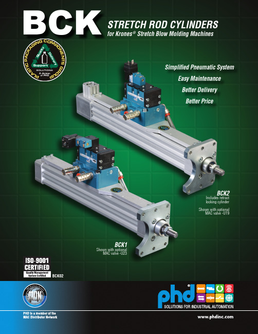
2) Standard stretch rod cylinder ordering number is as follows:
BCK1-5-50 x 390 - DR (-U19)
-U23 or -U19 options need to be specified for valve to be attached to unit.
deceleration • Cylinders easily field repairable to maximize investment • Internal shock pads standard on extend and retract • Food grade lubrication throughout
Options Pages 6 & 7
Parts List & Repair Kits Page 8
Shown with optional MAC valve -U19 installed
TO ORDER SPECIFY: Product Line, Series, Type, OEM Cylinder No., Design No., Bore Size, Metric Stroke, Mandatory Option, and Cylinder Options if required.
POSITION 2 FULL
EXTEND
CYLINDER (TOTAL STROKE)
POSITION 1 FULL
RETRACT
RETRACT END
RETRACT END
ROD EXTENSION
2 © Copyright 2014, by PHD, Inc. All Rights Reserved. Printed in the U.S.A.
克洛克 EK WF 120 ML 方块刺绳紧固机说明书

EK WF 120 ML – Optimum results thanks to square crimping SIMPLE AND SAFE CRIMPING USING INNOVATIVE TECHNOLOGYOPTIMUM RESULTS, WORKING IN SEQUENCEEK WF 120 ML – During crimping, high quality results are the be-all and end-all. We offer optimum solutions across the whole range of cables, combined with excellent ergonomics and simplified work sequences.The newly developed battery powered hydraulic crimpingtool EK WF 120 ML, will simplify your work and simul-taneously ensure optimum crimping quality. Using asquare-cam mechanism, the EK WF 120 ML crimpsboth DIN-compliant wire ferrules as well as insulatedwire ferrules, twin wire ferrules and insulated wireferrules for short-circuit protected lines. Here, the use ofinterchangeable crimping dies is completely unnecessarybecause the square mechanism adjusts flexibly to therespective cable end sleeve shape.HIGH QUALITY, WITH EASY MANUAL PROCESSING THANKS TO INNOVATIVE SQUARE CRIMPINGDIN-compliant insulated wire ferrules with Easy EntryInsulated twin wire ferrulesDIN-compliantwire ferrules, CuInsulated wire ferrules, forshort-circuit protected lines.6 - 120 mm²Precision-fi t crimping using comb-shaped molds ensures optimized distribution of forces and embeds the conductor in a corrugated shape. The result is that you get perfect working results over the entire range of wire ferrules shapes. All cross-sections from 6 to 120 mm² can be crimped using the EK WF 120 ML.Up to a wire ferrule length of 32 mm, only one crimping action is necessary, which means that you can crimp most wire ferrules in the cross-section range in just a single step.EK30IDMLEKWF120ML EK354MLEK50ML ES32MLWe have developed an optimum solution for over-coming the challenge of crimping the entire rangeof cables encountered in control cabinet construc-tion and mechanical engineering, while ensuringthe same uniform quality based on our new squarecrimping process. At the same time, this innovationis a key simplification, because it results in just onesystem and one geometry.In particular, the flexible type of crimping using thecomb-shaped die ensures optimum results evenwith old cables. This provides you with a uniformsolution for a wide range of conductors.SYSTEMATICALLY OPTIMIZED:FOR EVEN BETTER RESULTSKLAUKEEK WF 120 MLBATTERY POWERED HYDRAULIC CRIMPING TOOLFOR CABLE END SLEEVES 6 - 120 MM²SpecificationsThe new EK WF 120 ML is a perfect addition to the ML range from Klauke.Scope of supplyRechargeable battery 10.8 V / 1.5Ah, Li-ion (16.2 Wh)RAML1Charger for 10.8 V Li-ion recharge-able batteries, 230 VLGML1Plastic case KKMLCrimping range 6 - 120 mm²Stroke / opening width19 mmCrimping Force10 / 40 kNCrimping time1 to 5 s (dependent onthe crimping cross-sec-tion)Swiveling crimping head350°Battery charging time40 Min.Weight including battery 1.96 KgAmbient temp.-10 to +40 °Clights LEDArticle Art. no.Battery-powered hydrauliccrimping tool 6 - 120 mm²EKWF120MLKLAUKE OFFERS A TOOL PACKAGEControl cabinet construction normally involves the use of differ-ent cables, terminals and cable end sleeves. The three tools EK WF 120 ML, EK 30 ID ML and EK 50 ML from Klauke provide cablers/wirers with access to a package of solutions for the entire application range of cable types and cross-sections. Until now, efficiencies in control cabinet construction have been limited because the crimping of different cables has frequently called for the changing over of the required crimping dies, which costs time and money. Now, with the EK 30 ID ML and theEK WF 120 ML, Klauke is offering solutions that function without any changing over of crimping dies.FOR QUICK AND SAFE CRIMPING.Micro | Electromechanical crimping tool 0.14 - 50 mm² – EK 50 ML• T he Klauke micro with its intuitive PowerSense function combines theadvantages of manual press tools with the convenience of battery-poweredhydraulic press tools• Excellent crimping results with minimum energy use• One-button operating concept for controlling all tool functions• E lectronic control with locking function monitors full closing of the crimp-ing dies• Automatic return after completed work stepBattery powered hydraulic crimping tool for cable end sleeves 6 - 120 mm² – EK WF 120 ML•Innovative square crimping - the use of crimping dies is not necessary •Powerful 10.8 V Li-ion battery technology with charging level indicator •Closed head, swiveling •S imple and safe: one-button operating concept for controlling all tool functionsBattery powered hydraulic crimping tool 6 - 120 mm² – EK 30 ID ML•Indent crimping - changing of crimping dies is not necessary •Powerful 10.8 V Li-ion battery technology with charging level indicator •Closed head, hinged, swiveling •S imple and safe: one-button operating concept for controlling all tool functionsEFFICIENT WIRING WITH INNOVATIVE TECHNOLOGYTOGETHER Gustav Klauke GmbHTel.: +49 (0) 2191 / 907 - 0Auf dem Knapp 46***********************D-42855 Remscheid Get the latest information on products, services and promotionsby signing up to our newsletter:/NEWSLETTER © 2021 G u s t a v K l a u k e G m b H . A l l r i g h t s r e s e r v e d . T h e K l a u k e l o g o a n d t h e E m e r s o n l o g o a r e r e g i s t e r e d t r a d e m a r k s o f E m e r s o n E l e c t r i c C o . a n d i t s s u b s i d i a r i e s i n t h e U S A a n d i n o t h e r c o u n t r i e s . A l l o t h e r l o g o s a r e t h e p r o p e r t y o f t h e i r r e s p e c t i v e o w n e r s . S u b j e c t t o c h a n g e . B R E K W F 120M L 21G B 2.000 09/21 IFollow us!。
强威 4000磅调节式梁式吊车机所有者手册说明书
4000 lb. Adjustable Gantry CraneOwner’s ManualWARNING: Read carefully and understand all ASSEMBLY AND OPERATION INSTRUCTIONS before operating. Failure to follow the safety rules and other basic safety precautions may result in serious personal injury.Item #52523Thank you very much for choosing a Strongway™ product!For future reference, please complete the owner’s record below:Serial Number/Lot Date Code: ________________________________ Purchase Date: ____________________________________________ Save the receipt, warranty, and this manual. It is important that you read the entire manual to become familiar with this product before you begin using it.This Gantry Crane is designed for certain applications only. Northern Tool and Equipment is not responsible for issues arising from modification or improper use of this product such as an application for which it was not designed. We strongly recommend that this product not be modified and/or used for any application other than that for which it was designed.For technical questions, please call 1-800-222-5381.Intended Use (4)Technical Specifications (4)Important Safety Information (4)Safety Labels (6)Assembly Instructions (6)Operating Instructions (8)Maintenance (9)Parts Diagram (10)Parts List (11)Replacement Parts (11)Limited Warranty (12)The Gantry Crane is ideal for shops where heavy level lifting is essential.Capacity: 2 TonAdjustable Height: 7’ 11” - 11’ 9”Casters: 5”Assemble the crane loosely until the entire assembly is complete. Make certain that you have a large, clean, and uncluttered area for assembly. As the crane is large and heavy, you may have to lay out the different parts on their sides, and tighten and erect the entire assembly once complete.Step 1) Attach two Plates (#20) from two sides to the one end of the Crossbeam (#19). Secure with the four Bolts (#1), Washers (#2), Spring Washers (#3), and Nuts (#4). Repeat for theother end.Step 2) Attach each Inner Vertical Post Assembly to the Crossbeam (#19). Secure with the 8 Bolts (#1), Washers (#2), Spring Washers (#3), and Nuts (#4)Step 3) Attach the four Swivel Casters with Brake (#27) to the Base Assembly (#26). Apply grease to the zerk in each Caster.Step 4) Attach each Outer Vertical Post Assembly (#24) to each Base Assembly (#26), making certain that the slot at two sides of the Outer Vertical Post Assembly are facing theCasters’ direction. From the top, insert two (2) Bolts (#14) through the base of the OuterVertical Post Assembly, and into the Base Assembly (#26). Slip on the Washer (#2) andSpring Washer (#3) and secure by tightening the Nuts (#4).Step 5) Attach two Support Tubes (#22) to each Outer Vertical Post Assembly (#23). Insert the Bolt (#5) through the top of the Support Tube, and through the Eyelet. Slip on a Washer(#6) and Spring Washer (#7) and secure with the Nut (#8). Attach the other end of theSupport Tube to the Base Assembly with Bolts, Washers, Spring Washers, and Nuts.Repeat for all four Support Tubes.Step 6) Insert the Inner Vertical Post (#21) into the Outer Vertical Post (#23). Insert one (1) Pin of the Pins with Chain (part #18) through the slot and the Inner Vertical Post Hole so that itgoes all the way through to the other pin. Attach the Handle (#24) to the bracket on theside of Outer Vertical Post, insert the Bolt (#10) from the inside, slip on the Washer (#14)and Spring Washer (#15) and secure with the Nut (#11). Make sure the two (2) hooks ofthe Handle hold the two ends of the Pin (#18). Repeat for the other Post Assembly.Step 7) Tighten all the Bolts and Nuts securely and make certain that the entire assembly is tight and secure.Step 8) Test the crane according to manual and ANSI/ASME B30.17 standards.Step 1) Move the crane so that it is directly above the item to be lifted.Step 2) Securely fasten the item to the crane with the appropriate trolley or hoist.Step 3) Raising and lowering the Crossbeam requires two people. There is a Handle (#27) on each of the Outer Vertical Post Assemblies. To raise the Crossbeam, press the handle and theInner Vertical Post will be up by one hole, insert the other Pin into this hole to hold theposition. Pull out the original pin and hook the handle to the new positioned pin. Repeat toreach the height you need. The Inner Vertical Post Assembly has thirteen different stopping positions.# 52523 -2T∙For replacement parts and technical questions, please call Customer Service at 1-800-222-5381. ∙Not all product components are available for replacement. The illustrations provided are a convenient reference to the location and position of parts in the assembly sequence.∙When ordering parts, the following information will be required: item description, item model number, item serial number/item lot date code, and the replacement part reference number.∙The distributor reserves the rights to make design changes and or improvements to product lines and manuals without notice.Northern Tool and Equipment Company, Inc. ("We'' or '"Us'') warrants to the original purchaser only ("You'' or “Your”) that the Strongway product purchased will be free from material defects in both materials and workmanship, normal wear and tear excepted, for a period of one year from date of purchase. The foregoing warranty is valid only if the installation and use of the product is strictly in accordance with product instructions. There are no other warranties, express or implied, including the warranty of merchantability or fitness for a particular purpose. If the product does not comply with this limited warranty, Your sole and exclusive remedy is that We will, at our sole option and within a commercially reasonable time, either replace the product or product component without charge to You or refund the purchase price (less shipping). This limited warranty is not transferable.Limitations on the WarrantyThis limited warranty does not cover: (a) normal wear and tear; (b) damage through abuse, neglect, misuse, or as a result of any accident or in any other manner; (c) damage from misapplication, overloading, or improper installation; (d) improper maintenance and repair; and (e) product alteration in any manner by anyone other than Us, with the sole exception of alterations made pursuant to product instructions and in a workmanlike manner.Obligations of PurchaserYou must retain Your product purchase receipt to verify date of purchase and that You are the original purchaser. To make a warranty claim, contact Us at 1-800-222-5381, identify the product by make and model number, and follow the claim instructions that will be provided. The product and the purchase receipt must be provided to Us in order to process Your warranty claim. Any returned product that is replaced or refunded by Us becomes our property. You will be responsible for return shipping costs or costs related to Your return visit to a retail store.Remedy LimitsProduct replacement or a refund of the purchase price is Your sole remedy under this limited warranty or any other warranty related to the product. We shall not be liable for: service or labor charges or damage to Your property incurred in removing or replacing the product; any damages, including, without limitation, damages to tangible personal property or personal injury, related to Your improper use, installation, or maintenance of the product or product component; or any indirect, incidental or consequential damages of any kind for any reason.Assumption of RiskYou acknowledge and agree that any use of the product for any purpose other than the specifieduse(s) stated in the product instructions is at Your own risk.Governing LawThis limited warranty gives You specific legal rights, and You also may have other rights which vary from state to state. Some states do not allow limitations or exclusions on implied warranties or incidental or consequential damages, so the above limitations may not apply to You. This limited warranty is governed by the laws of the State of Minnesota, without regard to rules pertaining to conflicts of law. The state courts located in Dakota County, Minnesota shall have exclusive jurisdiction for any disputes relating to this warranty.Distributed by:Northern Tool & Equipment Company, Inc.Burnsville, Minnesota 55306Made in China。
讴科冷库使用手册说明书
关注未来,期待成为您的战略合作伙伴Focus On Future,We expect to be your strategic supplier讴科冷库使用手册冷冻/冷藏库使用说明及注意事项一、冷库安装前的准备工作•冷库设备安放在通风良好的干燥洁净环境中。
禁止在易燃、易爆、易腐蚀、有破坏绝缘的气体和导电尘埃的环境中使用本设备,禁止在不安全或有安全隐患的环境中使用本设备。
冷库安装之前,三相四线电源一定要到位。
•应有足够的空间进行冷库设备的安装,地面用混凝土抹面找平,一定要保证地面水平,以确保冷库拼装的整体效果。
地面耐力不小于3T/m2。
•冷库使用的电源为三相四线380V/50Hz(±10%),检查使用的电源是否与设备配套。
线载负荷是否符合要求而满足设备的的正常运行。
并配备冷库专用保护电闸。
•冷库设备一般配用风冷式冷凝器,不需要用水,特别适用于边远地区和缺水地区使用。
(有些情况下用户要求用水冷式冷凝器,此时用户要配置水池或水井)•冷库设备应有专人负责看管。
并了解用电常识和熟悉冷库的基本构造、性能。
二:冷库设备的安装先检查设备的外包装是否破损。
拆箱后对照装箱单检查所有随机文件和配件是否齐全。
检查机器的零部件是否因长途运输、搬运而松动、破损。
用户根据厂方提供的图纸和安装说明书进行安装调试。
当用户对冷库的常识不甚了解或对冷库安装毫无把握时,可与厂方达成协议,由厂方为您提供有偿服务。
三:冷库设备的使用常识和注意事项•冷库内放置的物品应留有一定空隙,利于冷气的流动。
库底板上要加木格保护层。
•冷库的制冷机组周围严禁堆放物体并远离发热源,以利于空气流动而充分散热,并定期用软毛刷清除制冷机组、散热器上的灰埃。
这些都是为了确保散热。
•冷库的库温设定应在规定的范围内,否则会增加冷库的工作负荷而损坏冷库元件。
储藏保鲜库库内温度设定在0~+5℃,冷冻库库内温度一般设定在0~-15℃,低温库库内温度一般设定在-10~-20℃。
红狮称重仪表说明书
CARD-CDC-50PROFIBUS-DP COMMUNICATIONS OPTION CARD1. DESCRIPTION (2)1.1. PNO Conformance and GSD File (3)2. SPECIFICATIONS (3)2.1. Fieldbus type (3)2.2. Bus interface (3)2.3. Network isolation (3)2.4. Power (3)2.5. Output power (3)2.6. Baud rates (3)2.7. Station address (3)2.8. Supported functions (3)2.9. Installation requirements (4)3. ORDERING INFORMATION (4)4. INSTALLING AN OPTION CARD (4)5. PRINCIPLE OF OPERATION (4)6. STATION ADDRESS (5)7. DIAGNOSTIC LEDs (5)7.1. Table 2 - LED Indication of PROFIBUS-DP Card Status (5)8. PARAMETERIZATION (6)8.1. Table 3 - User Parameter Data (6)9. CONFIGURATION (6)10. DATA EXCHANGE (6)10.1. Demand Write and Store Request Masks (6)10.2. Data Block Structure (7)10.3. Table 4 - Data Block Structure (7)11. PAX MANUAL MODE REGISTERS (7)11.1. CSR - Control Status Register (PAX Analog Only) (7)11.2. MMR - Auto/Manual Mode Register (PAXDP/PAXI/PAXCK) (8)11.3. SOR - Setpoint Output Register (PAXDP/PAXI/PAXCK) (8)11.4. (AOR) Analog Output Register (Not applicable to PAXCK) (9)11.5. Table 5 - Analog Output Signal Ranges (9)12. INSTALLATION AND CONNECTION (9)12.1. Installation Clearance Required - In Inches (mm) (9)12.2. PROFIBUS-DP Network Connection (9)Caution:cardscomponents.dischargeWarning:thetheaccessing the unit.Remove the main assembly from the rear of the case. Squeeze the finger holds on the rear cover, or use a small screwdriver to depress the side latches to release it from the case. It is not necessary to separate the rear cover from the main circuit card.Locate the option card connector for the serial communication card. Hold the unit by the rear cover, not the display board, when installing an option card.Install the option card by aligning the option card with the slot in the rear cover. Be sure the connector is fully engaged and the tab on the option card rests in the alignment slot on the display board.Slide the assembly back into the case. Be sure the rear cover latches fully into the case.PROFIBUS Network with access to an Input Data Block (data written to the PROFIBUS Network from the PAX) and an Output Data Block (data read from the PROFIBUS Using an internal high speed protocol, the card scans each PAX register in turn, continuously reading Input12.1.Installation Clearance Required - In Inches (mm)12.2.PROFIBUS-DP Network Connection PROFIBUS plug connectors such as Siemens6ES7 972-0BA10-0XA0 are recommended. Whenwiring the connector, be sure to observe the proper direction for data flows, indicated by the arrows onthe connector. When the PAX meter is the last。
基斯勒 2152b 型 nc 连接模块 cnc 连接系统 使用说明书
Page 1/4NC Joining Module NCFSfor Joining Operation with Small Center Distance2152B _000-763e -02.17NC Joining SystemThis information corresponds to the current state of knowledge. Kistler reserves the right to make technical changes. Liability for consequential damage resulting ©2007 ... 2017, Kistler Group, Eulachstrasse 22, 8408 Winterthur, Switzerland The joining module Type 2152B… with integral piezoelectric force sensor and two predefined measuring ranges of 25 and 15 kN is ideal for force-displacement monitored press-fit and joining processes in compact configurations.• Force signal• Integral charge amplifier• High measuring accuracy in two ranges • High speed • High rigidity • Precise guidance• High level of sensor overload protectionDescriptionThe NC joining module NCFS Type 2152B... consists of a ro-bust case with integral piezoelectric force sensor for measuring both compression and tension. Its motor has an absolute en-coder for exact positioning. The compression or tensile forces acting on the sensor's piezoelectric measuring element gen-erate a proportional electric charge converted by the integral charge amplifier into an analog voltage signal. The drive motor is an electronically commutated AC servo type handled by a matching controller to ensure constant rotational and hence translational speed. Standard functions such as block pressing, position pressing and force feedback controlled pressing as well as intermediate positioning are supported.The NC joining module NCFS can be operated with the In-draDrive servo amplifier in combination with maXYmos NC Type 5847... . The communication between IndraDrive and maXYmos NC takes place in real-time via SERCOS III. Several field bus slave interfaces are available onboard for customer controlling. PROFIBUS, PROFINET, EtherNet/IP or even Eth-erCAT can be used with the maXYmos NC at the customer's choosing. Quality data can be transmitted via the Ethernet interface through different protocols and a visualization via VNC ® or a data backup can be performed.Type 2152B...ApplicationThe NCFS joining module Type 2152B... is ideal for use in automated production systems. Its special design allows close workstation spacing. The previously practiced clocking of the stations is no longer performed, therefore reducing the throughput time The installation is possible vertically as well as horizontally. Fixation of the joining units at a machine frame is provided through flange mounting. Load-conforming dimen-sioned tapped holes for a tool receptacle are available at theplunger of the threaded spindle drive (Fig. 1).Page 2/42152B _000-763e -02.17This information corresponds to the current state of knowledge. Kistler reserves the right to make technical changes. Liability for consequential damage resulting ©2007 ... 2017, Kistler Group, Eulachstrasse 22, 8408 Winterthur, Switzerland Tel.+41522241111,Fax+41522241414,****************, Technical DataDimensions mm Fig. 1Assembly Flange assembly Weight kg 89Max. tool weight 1)kg 25Direction of measurement compression/ tension Measuring range kN 15, 25Length of stroke mm 350Practical repeatability mm 0,01Anti rotate tool fitting Fig. 1Max. speed mm/s 250Displacement sensor system Absolute encoder Resolution mm 0,001Force sensor piezoelectric Temperature range °C 10 ... 40Protection class IP54Linearity in all ranges%FSO ≤1Accuracy class force sensor % 0,5Service life of spindlecycles approx. 10 million(acc. to defined drive profile)Short strokemm ≤60Lubrication connection(exterior) number3Servo amplifier 2) Bosch-Rexroth Type 2180A...Standard interface SERCOS III (internal bus)Evaluation unit 3) maXYmos NC Type 5847...Standard interface PROFIBUS, PROFINET, EtherNet/IP , EtherCAT Power supplyVDC 24 ±5 %Flange Assembly/Tool FittingDimensionsThe radial forces (for example due to the weight of the tool) must be considered for the installation. An external guide may have to be provided for the plunger.Fig. 1:2) Servo amplifier see accessories data sheet 003-125 Type 2180A...3)Evaluation unit maXYmos NC Type 5847B... see data sheet 003-2721)Possible radial forces must be considered independent of the mounting.Permissible tool weight may have to be reduced for manual feed.A bending of the plunger depending on the tool weight must be considered for a horizontal installation.190Lubrication points Electrical connection points Warning high temperatures Attachment pointsPage 3/42152B _000-763e -02.17This information corresponds to the current state of knowledge. Kistler reservesthe right to make technical changes. Liability for consequential damage resulting ©2007 ... 2017, Kistler Group, Eulachstrasse 22, 8408 Winterthur, Switzerland Tel.+41522241111,Fax+41522241414,****************, Fig. 2: Functional principle of NC joining system with NC joining module NCFS Type 2152B... and maXYmos NC Type 5847...Included Accessories• NoneOptional Accessories Type/Art. No.• Evaluation unit maXYmos NC 4)(MEM) 5847...• Bearing rail adapter for 35 mm Cap rail including 2 fastening screws M3x10 5700A31• Display module (DIM) with pedestal 5877AZ000• Connection cable maXYmos MEM on DIM, length 5 m 1200A161A5• Servo amplifier 2)2180A...CableType/Art. No.• NCFS 25 motor cable, length 5 m RKL4302KSM341600-5• NCFS MSK Feedback cable, length 5 m RKG4200KSM303500-5• maXYmos Force transmitter cable, length 5 m KSM18028884-5• SERCOS III connection cable, length 5 m KSM18029160-5• Safety zone box cable, 2 cables required), length 1 m KSM18029161-1Other length on request.Functional Principle with maXYmos NC Type 5847...2) Servo amplifier see accessories data sheet 003-125 Type 2180A...4)Evaluation unit maXYmos NC Type 5847B... see data sheet 003-272IndraDrive MotoransteuerungKSM18029160-5Absolutwertgeber AC-Servomotor zonenmodul (Kabellänge max. 5 m)Sicherheitszonenbox piezoelektrischerSafety zone box Servo amplifiersafety zone box KSM18029161-1KSM18029160-5Motor Control Absoulte encoder1200A161A...(Cable length max. 5 m)Power section for NC joining module 152B 25... NCFS0025Ordering Key Servo Amplifier for NCFSPage 4/42152B _000-763e -02.17This information corresponds to the current state of knowledge. Kistler reserves the right to make technical changes. Liability for consequential damage resulting ©2007 ... 2017, Kistler Group, Eulachstrasse 22, 8408 Winterthur, Switzerland Tel.+41522241111,Fax+41522241414,****************, Ordering Example Type 2152B25350NC Joining Module NCFS Type 2152B..., nominal force, measuring range 1: 25 kN, measuring range 2: 15 kN 25 kN , stroke 350 mmPossible AssemblyFig. 3: Extremly narrow assembly space requirements from NC joining module NCFSOrdering Key。
- 1、下载文档前请自行甄别文档内容的完整性,平台不提供额外的编辑、内容补充、找答案等附加服务。
- 2、"仅部分预览"的文档,不可在线预览部分如存在完整性等问题,可反馈申请退款(可完整预览的文档不适用该条件!)。
- 3、如文档侵犯您的权益,请联系客服反馈,我们会尽快为您处理(人工客服工作时间:9:00-18:30)。
User's guideV5.0.7Skelion- 2 - ÍndiceÍndice_______________________________________________________________________2 1Installation______________________________________________________________4 1.1Update___________________________________________________________________5 1.2Uninstall__________________________________________________________________5 1.3Write rights_______________________________________________________________61.3.1Write rights in Windows OS________________________________________________________61.3.2Write rights in MAC OS___________________________________________________________7 1.4Pro version and Free version_________________________________________________8 2Units____________________________________________________________________9 3Geolocating model_________________________________________________________9 4Drawing the building_____________________________________________________11 5Skelion's toolbar_________________________________________________________135.1 Azimuth convention___________________________________________________145.2 Rotate north and Restore north_____________________________________155.3 Surface azimuth and tilt________________________________________________165.4 Insert solar components________________________________________________165.4.1Insert following an edge. ___________________________________________165.4.2Multiple faces __________________________________________185.4.3Non planar surface _________________________________________________195.5 Sunny area___________________________________________________________22 5.6 Minimal Shading criterion_____________________________________________22 5.7 Report______________________________________________________________23 5.8 Face report dialog____________________________________________________23 5.9ARRAY MODE______________________________________________________23 5.10 JRC PVGYS EUROPE y JRC PVGYS AFRICA_______________________23 5.11 PVWATS report______________________________________________________24Índice 5.12 Project face to mesh____________________________________________________245.13 Surface report________________________________________________________24 5.14 Change UTM model origin______________________________________________25 5.15 Drop________________________________________________________________26 5.16 Sun Path Chart_______________________________________________________26 5.17 Help_________________________________________________________________265.18 About_______________________________________________________________26 6Differences between pro and free version_____________________________________27 7Links:_________________________________________________________________28- 3 -Skelion- 4 -1 InstallationSkelion is a plug-in of Sketchup. To install it you need SketchUp (free or pro) running on your computer.The installation process is the same of any plug-in of Sketchup.Plug-ins installation on Sketchup:/sketchup/bin/answer.py?hl=en&answer=38583/thoughts/2012/01/installing-plugins-for-google-sketchup/ User must have “write rights ” in Plugins folde r to use Skelion.There are 2 forms of install a plugin on Sket c hUp, manually or usingSketchUP/Preferences/Extension/Install Extension.We recommend the manual way because is easy to install and uninstall, and you can control the filesyou copy.Steps:∙ Change the extension of the file from .rbz to .zip. ∙ Unzip the file:∙ Store unzipped files in Plugins folder of Sketchup: Windows OS:C:\Program Files (x86)\Google\Google SketchUp 8\PluginsMAC OSYour Hard disk name/Library/Application Support/Google SketchUp 8/SketchUp/PluginsNote that this path in MAC is under the root HD loc ation and not the user folder! It is also notinside the Sketc hUp applic ation pac kage. Both of these loc ations are something that OSX users often mistakenly pick first time they try to install a plugin.There is an error in MAC and some users can’t see the files of their hard disk. In this case they should fixthis error to will be able to install Skelion.Plugins folder with Sketchup default files plus Skelion files (MAC OS)Skelion- 5 -Plugins folder with skelion files (Windows OS)1.1 UpdateDelete old Skelion files and folders (View above image):∙ “2d_simplex_bool” folder ∙ “_skelion” folder∙ “2d_simplex_bool_ext.rb” ∙ “skelion_ext.rb”You must follow same pro c ess of installation. Remember if you have modified“dimension_modules.csv ”, manually or creating your solar panels from Skelion dialog, you must do a backup because this file will be overwritten.1.2 UninstallVersion 5.0.6 and lower:Go to Plugins folder and delete the 2 files and 2 folders of picture:Skelion- 6 -Version 5.0.7 or higher:Go to Plugins folder and delete “skelion” folder and “skelion.rb” file.1.3 Write rightsSkelion needs write rights in plugins folder to write in files like “dimension_modules.csv”. If you don’thave write rights you receive this message and Skelion won’t start.Message of error when Plugins don’t have write rights1.3.1Write rights in Windows OSSecurity tab of plugins folder.Go to “C:\Program Files (x86)\Sketc hUp” (Sketc hup 2013)" or “C:\Program Files (x86)\Google\GoogleSketchUp 8\” (SketchUP 8).Right click on the Plugins folder and selected "Properties".Selec t the sec urity tab, selec ted yourself as the "Group or user names:", and allow yourself “Fullcontrol”.Check in General tab that “read only” is unchecked for all files and folders inside Plugins.Skelion- 7 -General tab of Plugins folder.1.3.2 Write rights in MAC OSRight click over Plugins folder and select Get Info.Clic k the disc losure triangle next to Sharing & Permissions to display permissions for the selec tedfolder.Click the lock and authenticate with an administrator account.Use the menus next to users and groups to add Read & Write permissions to you.When you’re finished, close the Info window. Changes are effective immediately.Skelion1.4Pro version and Free versionSkelion runs 15 days in pro mode. After that, free version is activated.If you want to use Pro version, you must buy a license in and insert the serial in the web dialog you can watch pushing "About" button in Skelion toolbar.- 8 -Skelion- 9 -2 UnitsLength: You can change defualt length in SketchUp—model info – units. In SketchUp you can draw aline and set length like: 8 m, 8cm, 8mm, 8”, 8 (default unit is used in this case).Skelion dialogs works in same way of SketchUp.For other units different from length, used in Skelion dialogs, user must write only the number. Usedunit must be the unit specified in the left.You can write 220, but not 2.2kW.You can write 8cm or 8 m or 8”… any SketchUp valid unit.3 Geolocating modelFirst step in Sketchup is geolocate the model. Go to View - toolbars - Google.Google ToolbarPress this button . "Add Location", you have access to Google Earth and you can geolocate theplac e. You c an use "Google earth position" to c opy and paste latitude and longitude from Google Earth to Sketchup window./p/googleearth-autohotkey/ When you geolocate the model you achieve:∙ Satellite picture (Windows - Layers - Google Earth Snapshot) ∙ 3D mesh of surface. (Windows - Layers - Google Earth Terrain)∙ Real shadows of geographic position selected for any time of the year.(Window - Shadows)∙ You can measure distances using"tape measure" tool (View - toolbar - large tool set).Shadows windowGoogle Earth Terrain layerLayers widnowGoogle Earth Snapshot layerSkelion - 10 -4 Drawing the buildingIn Sketchup there are several forms to draw the building:∙ Downloading directly from Google Earth.∙ Drawing from satellite picture directly. Geo-modeling with SketchUP . /intl/en/training/videos/gsuge.html/sketchup/bin/answer.py?hl=en&answer=167458∙ Exporting 2d or 3d planes from other programs like AutoCAD.To download a building from Google Earth you must follow next steps:∙ Activate ·layer "3D Buildings" to find out if building is drawing in 3D.∙ Disable 3D imagery in Properties. Then legacy 3D building you can download will be showed onGoogle Earth. (3D imagery are 3d buildings from Google you can not download).∙ Clic k over building if you find. If building c an be exported to Sketc hup a window will be opened.∙ Click over building picture of window.∙If building is free to download, "3d warehouse" will be opened inside Google Earth and you willbe able to download the building in Sketchup format.Google Earth with layer "3d building" active.3d warehouse of Google5Skelion's toolbar To activate Skelion's toolbar go to View - toolbars - Skelion.Names of buttons:Surface azimuth and tiltInsert solar componentsSunnyareaMinimal Shading criterionRotatenorthRestorenorthToggle Array modeReportFace report dialogJRC PVGYS EUROPEJRC PVGYS AFRICAPVWATSreportProject face to meshSurfa c ereportChange UTM model originDropPVSYSTexporterSun Path ChartAzimuthc onventionHelpAboutAlso you can find them in commands toolbar, in Plugins/Skelion5.1 AzimuthconventionWeb dialog Azimuth conventionSelect the convention you want and close the web dialog.Any azimuth you use in Skelion from now will follow this convention. You can close Sketchup and next time convention will be the same.PVGYS and PVWATTS are external programs to Skelion, so when they are opened, azimuth is converted to the convention they use. PVWATTS use 360º convention and PVGYS use 180 conventions in north hemisphere but for the entire world.5.2 Rotate north and Restore northIn Sketchup true north can point in any direction. With Solar North toolbar you can change it.Solar North toolbarSkelion use Y+ axis default (green axis) like true north. So you must take into account Sketchup truenorth (orange axis) must have same direction of Y+axis (green). You can see Sketchup true north clicking .Skechup 8 M2 current version, import 3d mesh and satellite image slightly rotated when you geolocatea model. That is bec ause true north value c hanges to a value between 0º and 2º. In the pic ture you c an appreciate true north (orange axis) differ 1.74º from green axis.Button "Rotate north" let us rotate all model to give true north same direction of Y+. Then Skelion datawill be right."Restore north" button rotate model to original position, just in case you want to return.Midi d'ossau Latitude, Longitude: 42.84224 -0.4358915.3Surface azimuth and tiltPress the button and select faces to watch his azimuth and tilt in the opened window.5.4Insert solar componentsThis button give access to three different web dialogs, in function of the objects selected before pressthe button:∙ Selecting and edge and a face: INSERT FOLLOWING AN EDGE∙Selecting some faces MULTIPLEFACES∙ Selecting 3d mesh: NON PLANAR SURFACE5.4.1 Insert following an edge.To open the web dialog "Insert following an edge" user must select one edge and one face and pressthe button "insert solar components". Selected edge can be any edge of the face boundary or any edge in same plane of the face.Orientation:Components will follow edge. (You can reverse direction if you want to insert just in the opposite way ofdefault direction.)Component:Component selectionThere are three possibilities to insert a component:Choose one from the list.Load your own component.Draw your own component in Sketchup and click right button over it, and select “save as” componet. Before save, component must be oriented in an specific form, because Skelion needs to know how to insert it: ∙Z+ axis must be perpendicular to “capitation surface∙Origin will be the point of insertion over the face.∙If capitation surface is smaller than bounding box then you need to mark it with right button- Skelion- Mark capitation surface. Marking this, Skelion will be able to calculate right shadowdistances between rows. If capitation surface is equal to bounding box, then this step is notnecessary.Captation surface smaller than bounding box.You can learn more about components in:/intl/en/training/videos/new_to_gsu.html Create you own component adding length, width, depth.You can add more solar panels to default list writing in the file "dimension_modules.csv" or clicking thesave checkbox when you create one. This file is located in ".../Plugins/_skelion".Right axes situation in component.Right axes sitution in component.Components inserted by Skelion.Components inserted by Skelion.Other component parameters:Parameters to insert a component."Stack components" let us pile up components.With "Rows alignment" you can adjust all components to a grid or let rows to maximize the space.Pitch:Pitch.User can insert his own pitch or use any of the options proposed by Skelion.Pitch.Insert:You can insert all components at same time in the face with “Fill face” button or going row by row using “Fill in rows”. Using this last button, you can click in any point rear the last row inserted. Skelion will insert next row mataining the minimum pitch you selected, but if you click in a point with more pitch, then the next row will be inserted in that point.5.4.2 Multiple facesMultiple faces dialogYou can access to dialog "multiple faces" opening some faces and clicking the button "Insert solar components". (Skelion will use only faces. Other objects of selection will be discarded).Selection of some faces. "Multiple faces" r = 0 There are 3 options to insert solar components:∙and of component: Skelion will insert components in all selected faces. (In coplanar case, Skelion will try to follow the tilt of the roof.∙: Solar component will be inserted following roof tilt. If roof tilt is 0 then program will try to follow any edge of the roof.∙r: Solar component will be inserted following roof tilt If you want coplanar you must insert r = 0. If roof tilt is 0 then program will try to follow any edge of the roof.5.4.3 Non planar surface"Non planar surface" allows you to insert components in 3d mesh, like curved roofs or solar ground mount systems.To use "Non planar surface" you must follow next steps:Select mesh with main surface and inner surfaces in which no components will be inserted.Boundaries of each surface must be "NO SOFT" and the others must be "SOFT" to let Skelion detect surfaces of the mesh.Press button "Insert solar components"."Surface tool" will be activated. Pick with the mouse over a point in the mesh to insert first row. You must select other tool to deactivate "Surface tool".Then, when you click "Non planar surface" a dialog will be opened and we must insert azimuth, tilt, component and times to calculate the pitch. Pitch used between rows will be different and will be the worst of all the components for the times specified by the user. If you want only one hour you must insert the same time twice.If c omponent has "c onstruc tion points" you c an use "surfac e report" to make a report about position of construction points and and of selected edge. You can use any type of component, solar panel, solar ground structure...All inserted components will have same azimuth and same tilt and there aren't shadows between the times inserted in dialogIn c omplex surfac es sometimes you must exec ute twic e the program bec ause rows follow only one direction when are inserted.Components with 0ºe 30º (180ºconv).Components with 0ºe 30º (180ºconv).Rules to use "non planar surface":∙NO HOLES in mesh.Mesh with a hole.Right mesh.∙All faces must have right orientation. (Use reverse face to fix mesh)Mesh with reversed faces.Right mesh.∙Boundary of any surfaces must be "NO SOFT". Rest of edges must be "SOFT".Mesh with 3 surfaces and boundaries NO SOFT.∙Selec t all surfac es, the main surfac es and the others where solar c omponents won't be inserted..Mesh with all selected.∙Main surfaces can't share boundary with the others surfaces.Main surface share boundary with other surface. Right mesh.∙Check shadows. Sometimes last rows or components near the boundaries can be erroneous.area5.5 SunnySelecting a face you can find out the zone with no shadows at one time or between two times. (If you want only one time, repeat same time twice in dialog.)To improve speed of algorithm you can hide all elements not useful with normal methods of Sketchup: hide geometry, hide layers and cast shadows.Face before use "sunny area" Face after use "sunny area"5.6Minimal Shading criterionSelect a face and press the button to find out the area that accomplish this rule5.7 Report"Report" button returns the number of components inserted by Skelion, and their power. You cancopy the report to excel if you want.Data is arranged in 3 forms:∙ By face and solar component model.∙ By groups with same tilt and azimuthand solar component model. ∙ By arraysA new layers will be create with numbered faces.Layer TX:Face_names active.5.8 Face report dialogPress this button to open face report window. After this select any face. All the information of the facewill be showed in the window. Remember this information is static. If you delete components, you must update model clicking report analysis, PVGYS or PVWATTS.5.9ARRAY MODEClicking this button solar components turn to white. You can select each component and colour it with add material to mark the arrays.5.10JRC PVGYS EUROPE y JRC PVGYS AFRICAWith button "PVGYS" or "PVGYS" AFRICA you c an find out energy of solar c omponents.Skelion links with JRC web sending all the necessary data to the web. PVGYS web is valid only for one tilt and one azimuth, so Skelion repeat the process the number of times equal to the groups with same tilt and azimuth of the model.Skelion sends the following data:∙ Azimuth and tilt . Azimuth is transformed automatically to PVGYS convention. (180º northhemisphere convention for the entire world). ∙ Technology ∙ Group power. ∙ Location.You must follow an order closing windows and you can close white window. Location is added automatically but you must click search button.1. Click calculate2.Close main window.3.Repeat the process for each group.You can select and copy the result in Excel.5.11 PVWATS reportWith button "PVWATTS" you can find out the energy of Sketchup model in USA. Skelion links with NREL web, sending all necessary data. PVWATTS is valid for one azimuth and tilt, so Skelion repeat process a number of times equal to groups with same tilt and azimuth in the Sketchup model.Skelion sends the following data:∙Azimuth and tilt . Azimuth is transformed automatically to convention used by PVWATTS.360 convention.∙Group power.∙Location.You can copy and paste the report in excel.5.12Project face to meshWith button "project face to mesh", you can obtain the face more similar to the mesh below it. Select the face and press the button "project face to mesh". You can use it to make fast layouts of ground mount systems.Face ready to project. Result of face projected.5.13 Surface report"Surface report" gives information about position of solar components inserted.Component must have "Construc tion Points" inside. You c an insert "Construc tion Points" using the plugin "Projections" from Didier Bur. Download in:http://rhin.crai.archi.fr/rld/plugin_details.php?id=671You next to follow next steps to use "Surface report":∙Hide all elements over and below surface.∙Select one edge of component and press .The report generated inform about:∙Coordinates UTM of all "construction point" of each component.∙Coordinates UTM of projections of "constructions points" over surface, following direction of selected edge.∙Distance of each points to surface.∙Azimuth and tilt from selected edge in all components.5.14Change UTM model originSketchup origin point (0,0,0) in the real world is the same point that we use to geolocate the model:Window - model – geolocation .Knowing this correlation we can find out the coordinates of any point of the model in the real world.“Surface report” use this correlation to calculate the position of some points of the model in real world. If we are working over “Google Earth Terrain Layer” we must do nothing. But if we are working with amesh imported from AutoCad or a mesh from a topographer we must set the origin of Sketc hup in the right place.To achieve a good correlation between real world and model we must follow the next steps:1- Know the coordinates of one point of the model. (Latitud, longitude or UTM coordinates).2- Move all the model, setting this point in Sketchup origin (0,0,0)3- Geolocate the model with the real position of this point. In window-model-geolocation we must set latitude and longitude.If we know UTM coordinates instead of latitude and longitude we can use “Change UTM origin” to geolocate the model.Origin and reference point in different places. Equal origin and reference point5.15 DropThis tool let you to drop an instanc e vertic ally until find a fac e. It works selec ting a group of components inside, or selecting some components.You must hide all elements between the components you want to drop and the mesh. The components will drop until their origin touch the face.5.16 PVSYST EXPORTERUsing this feature you can save in your hard disk a file with Helios 3d format. In PVSYST you can go to Near Shadings – Consrtruction Perspective – File Import Helios 3d, and select the Helios3d file you saved with Skelion. (In current version of PVSYST shadows of objects imported in this way are not calculated)5.17 Sun Path ChartThis button let us plot sun path chart in cartesian or polar coordenades any day of the year. You can see very similar plots in:/AboutSunCharts.html5.18 HelpDialog to access this document.5.19 AboutClick to insert serial of pro version.6 Differences between pro and free versionFree versionSurface azimuth and tiltInsert in one faceInsert in multiple facesSun Path ChartAzimuth c onventionVersion ProSurface azimuth and tiltInsert in one face Insert in multiple facesInsert in non planar surfaces Fix north Sunny areaMinimal Shading criterion Toggle Arraymode Report Face report dialog JRC PVGYS EUROPEJRC PVGYS AFRICAPVWATS reportProject face to meshSurfa c e reportChange UTM model originDropPVSYST exporter Sun Path ChartAzimuth c onvention7Links: Learning Sketchup:/enSketchup video tutorials/learn/videos?playlist=58 Geo-modeling/en/article/167458 Google earth position:/p/googleearth-autohotkey/ Projections:http://rhin.crai.archi.fr/rld/plugin_details.php?id=671 3d warehouse:/products/3D-warehouse。