DZ267LE-32使用说明书
驱动器说明书
L297+L298步进电机驱动控制板说明书一、板子跳线器说明:所有跳线都在左边,则由单片机控制。
1、靠近光偶的短路冒打在CLK-555方向时有板上的555提供时钟给驱动器;打在CLK-CP U时右用户CPU提供时钟给驱动器。
2、JT5打在右边:297的HALF/FULL(全速/半速)脚接GND了默认为FULL模式了;JT5打在左边:297的HALF/FULL脚空了电机模式用户自己控制。
3、JT6打在右边:297的CW/CCW脚(方向)接GND了默认为顺时针转动模式了;JT6打在左边:297的CW/CCW脚空了电机正反转模式用户自己控制。
二、按键说明:板子使用全新的L297作为控制芯片 L298作为驱动芯片板载NE555时钟电路为L297提供CLK因此该版在不需要外部控制的情况下就可以工作板载3个控制按键EN - 使能CW - 反向旋转HF - 半速旋转通过按键就可以直接控制电机的正反转、全速/半速和使能。
三、基本功能描述:通过光藕隔离之后将CLK CW HF EN四个基本控制端引出单片机等可以非常方便的控制电路的工作这个板子改进的地方比较多也方便研究使用。
板子使用1N5822快速二极管作为续流器件其速度要远远快于整流桥的 L298和电机能够提供更完善的有效的保护。
模块供电+ 5V(L297和L298控制供电) +12V(根据电机最低4V最高16V)给电机供电。
电机输出接口包括: +12V 四相输出 GND(请根据您的电机连接)。
控制输入接口包括: GND CLK EN CW HF。
EN:高电平停止,低电平使能。
RET:高电平停止,低电平使能。
C/CW:高电平逆时针,低电平顺时针。
H/HD:高电平全速,低电平半速。
CLK:时钟脉冲。
需要特别说明的是:为了测试方便在板子上设置了NE555构成的一个低频时钟源(使用时跳线冒打在CLK-555处),当您使用外部的时钟信号控制电机的转速时必须跳线冒打在CLK -CPU处否则外部时钟是不会传到L297里面。
正泰集团3C安全认证证介绍模板一览表之欧阳美创编
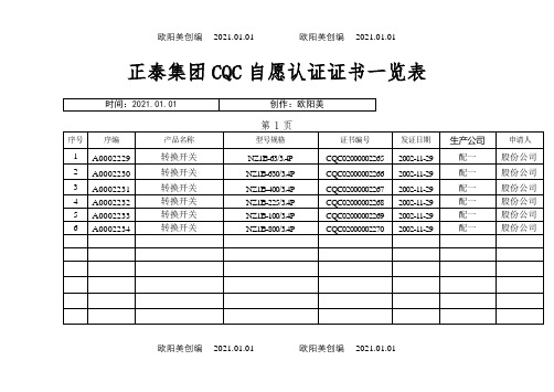
正泰集团CQC自愿认证证书一览表欧阳美创编 2021.01.01 欧阳美创编 2021.01.01正泰集团3C安全认证证书一览表欧阳美创编 2021.01.01 欧阳美创编 2021.01.01欧阳美创编 2021.01.01 欧阳美创编 2021.01.01正泰集团3C安全认证证书一览表欧阳美创编 2021.01.01 欧阳美创编 2021.01.01正泰集团3C安全认证证书一览表欧阳美创编 2021.01.01 欧阳美创编 2021.01.01欧阳美创编 2021.01.01 欧阳美创编 2021.01.01正泰集团3C安全认证证书一览表欧阳美创编 2021.01.01 欧阳美创编 2021.01.01正泰集团3C安全认证证书一览表欧阳美创编 2021.01.01 欧阳美创编 2021.01.01正泰集团3C安全认证证书一览表欧阳美创编 2021.01.01 欧阳美创编 2021.01.01正泰集团3C安全认证证书一览表欧阳美创编 2021.01.01 欧阳美创编 2021.01.01正泰集团3C安全认证证书一览表欧阳美创编 2021.01.01 欧阳美创编 2021.01.01正泰集团3C安全认证证书一览表欧阳美创编 2021.01.01 欧阳美创编 2021.01.01正泰集团3C安全认证证书一览表欧阳美创编 2021.01.01 欧阳美创编 2021.01.01正泰集团3C安全认证证书一览表欧阳美创编 2021.01.01 欧阳美创编 2021.01.01欧阳美创编 2021.01.01 欧阳美创编 2021.01.01正泰集团3C安全认证证书一览表欧阳美创编 2021.01.01 欧阳美创编 2021.01.01正泰集团3C安全认证证书一览表欧阳美创编 2021.01.01 欧阳美创编 2021.01.01正泰集团3C安全认证证书一览表欧阳美创编 2021.01.01 欧阳美创编 2021.01.01正泰集团3C安全认证证书一览表欧阳美创编 2021.01.01 欧阳美创编 2021.01.01正泰集团3C安全认证证书一览表欧阳美创编 2021.01.01 欧阳美创编 2021.01.01正泰集团3C安全认证证书一览表欧阳美创编 2021.01.01 欧阳美创编 2021.01.01正泰集团3C安全认证证书一览表欧阳美创编 2021.01.01 欧阳美创编 2021.01.01欧阳美创编 2021.01.01 欧阳美创编 2021.01.01正泰集团3C安全认证证书一览表欧阳美创编 2021.01.01 欧阳美创编 2021.01.01正泰集团3C安全认证证书一览表欧阳美创编 2021.01.01 欧阳美创编 2021.01.01正泰集团3C安全认证证书一览表欧阳美创编 2021.01.01 欧阳美创编 2021.01.01正泰集团3C安全认证证书一览表欧阳美创编 2021.01.01 欧阳美创编 2021.01.01正泰集团3C安全认证证书一览表第22页欧阳美创编 2021.01.01 欧阳美创编 2021.01.01欧阳美创编 2021.01.01 欧阳美创编 2021.01.01欧阳美创编 2021.01.01 欧阳美创编 2021.01.01。
sscom32使用说明

注意:把文件夹拷贝到硬盘后,取消其只读属性,再运行。
如上图设置好通讯的参数,波特率要和仪表一致。
发送的第2、3 字符30 31 为仪表地址。
当仪表地址Addr 设为2时,相应发送数据为30 32。
Addr为25时,发送的第2、3 字符为32 35。
特别注意:字符串输入框中的数据格式。
显示方式选HEX显示则以16进制显示仪表返回的数据。
不同的型号仪表发送的数据格式不同,要根据说明书的通讯协议格式。
如智能测控仪仪表和巡检仪表一般发送:04 30 31 52 30 30 05
PID调节仪读PV发送04 30 31 52 30 30 05
读HA发送04 30 31 52 30 31 05
写HA =1230发送04 30 31 57 30 31 2B 31 32 33 30 2E 03
流量积算仪表读测量值累计量发送04 30 31 52 05
注意:把文件夹拷贝到硬盘后,取消其只读属性,再运行。
SSC32舵机控制器用户手册

概述:USBSSC32路舵机控制是专为人形机器人、蜘蛛机器人、机械手等多舵机使用而量身定做的多路舵机控制器。
该控制器不但保留了原版的所有功能,还在原版的基础上作了升级,将原来的RS232串口改成了USB接口,方便电脑没有串口的用户使用。
控制器还增加蓝牙接口,可实现无线远程控制。
USBSSC32路舵机控制控制方式包括实时、定时、定速控制等,与lynxmotion的控制软件完全兼容.参数:1.输出通道:32路(脉冲调制输出或TTL电平输出);2.舵机供电:根据所接舵机额定电压供电,典型DC4.8V~6V;3.逻辑供电:DC6V~12V或USB供电(具有自恢复保险丝,调试时使用);4.驱动分辨率:1uS,0.09°;5.驱动速度分辨率:1uS/秒,0.09°/秒;6.通讯接口:USB/TTL串口接口;7.串口波特率:2400、9600、38.4k、115.2k可设置;接口描述:SSC32舵机控制板接口如下图所示:1.16-31号舵机信号控制引脚,其中G表示GND(黑色排针);V表示VCC(红色排针);S表示信号控制引脚(白色排针)。
使用时不要把线接反。
2.0-15号舵机信号控制引脚,其中G表示GND(黑色排针);V表示VCC(红色排针);S表示信号控制引脚(白色排针)。
使用时不要把线接反。
3.主控制芯片,采用DIP28脚的Atmega8L单片机,工作频率14.7456MHZ。
4.16-31号舵机控制电源输入,可以用来驱动一般的模拟或者是数字舵机。
工作电压4.8V -6V,可以使用5片镍氢电池组供电,其中VS2接电源正极,GND接电源负极。
5.0-15号舵机控制电源输入,可以用来驱动一般的模拟或者是数字舵机。
工作电压4.8V -6V,可以使用5片镍氢电池组供电,其中VS1接电源正极,GND接电源负极。
6.逻辑供电输入端,输入电压范围7.5-15V,通过内部的降压给电源提供稳定的5V电源,其中VIN接电源的正极,GND接电源的负极。
DM322E 2-Phase Digital Stepper Drive用户手册说明书

User ManualDM322E2-Phase Digital Stepper DriveRevision 1.0©2016 China Leadshine Technology Co., Ltd.Address: Floor 11, Block A3, Nanshan iPark, Xueyuan Avenue 1001, Shenzhen, Guangdong, 518055, China Tel: (86)755-26409254 Fax: (86)755-26402718Web: Sales: *******************Support: ******************NoticeRead this manual carefully before any assembling and using. Incorrect handling of products in this manual can result in injury and damage to persons and machinery. Strictly adhere to the technical information regarding installation requirements.This manual is not for use or disclosure outside of Leadshine except under permission. All rights are reserved. No part of this manual shall be reproduced, stored in retrieval form, or transmitted by any means, electronic, mechanical, photocopying, recording, or otherwise without approval from Leadshine. While every precaution has been taken in the preparation of the book, Leadshine assumes no responsibility for errors or omissions. Neither is any liability assumed for damages resulting from the use of the information contained herein.This document is proprietary information of Leadshine that is furnished for customer use ONLY. Information in this document is subject to change without notice and does not represent a commitment on the part of Leadshine. Therefore, information contained in this manual may be updated from time-to-time due to product improvements, etc., and may not conform in every respect to former issues.Record of RevisionsRevision Date Description of Release1.0 Dec, 2016 Initial ReleaseTable of Contents1. Introductions (1)1.1 Features (1)1.2 Applications (1)2. Specifications (1)2.1 Electrical Specifications (1)2.2 Environment (2)2.3 Mechanical Specifications (2)2.4 Elimination of Heat (2)3. Connection Pin Assignments and LED Indication (3)3.1 Connector P1 Configurations (3)3.2 Connector P2 Configurations (3)3.3 LED Light Indication (4)4. Control Signal Connector (P1) Interface (4)5. Motor Connection (5)5.1 Connections of 4-lead Motor (5)5.2 Connections of 6-lead Motor (5)5.2.1 Half Coil Configuration (5)5.2.2 Full Coil Configuration (5)5.3 Connections of 8-lead Motor (6)5.3.1 Series Connection (6)5.3.2 Parallel Connection (6)6. Power Supply Selection (6)6.1 Regulated or Unregulated Power Supply (7)6.2 Power Supply Sharing (7)6.3 Selecting Supply V oltage (7)7. DIP Switch Configurations (7)7.1 Microstep Resolution Configurations (7)7.2 Current Configurations (8)7.2.1 Dynamic Current Configurations (8)7.2.2 Standstill Current Configuration (8)7.3 Automatic Motor Matching & Self Configuration (8)8. Wiring Notes (9)9. Typical Connection (9)10. Sequence Chart of Control Signals (9)11. Protection Functions (10)12. Troubleshooting (11)13. Warranty (12)14. Contact Us (12)1. IntroductionsThe DM322E is a digital stepper drive with simple design and easy setup. By implementing Leadshine advanced stepper control technology, this stepper drive is able to power 2-phase and 4 phase stepper motors smoothly with optimal torque and low motor heating & noise. Its operating voltage is 18-30VDC and it can output up to 2.2A current. All the micro step and output current are done via DIP switches. Therefore, the DM322E are ideal choices for applications requiring simple step & direction control of NEMA11, 14, 16, 17 stepper motors.1.1 Features●Anti-Resonance for optimal torque, extra smooth motion, low motor heating and noise●Motor auto-identification and parameter auto-configuration for optimal torque from wide-range motors●Step & direction (PUL/DIR) control●Multi-Stepping for smooth motor movement●Optically isolated inputs●Input voltage 18-30VDC●8 selectable micro-step resolutions of 400-12800 via DIP switches●8 selectable output current settings of 0.3 – 2.2A via DIP switches●Soft-start with no “jump” when powered on●Pulse input frequency up to 70 KHz.●Automatic idle-current reduction●Protections for over-voltage and over-current1.2 ApplicationsThe DM322E stepper drive are designed to power 2 phase (1.8°) or 4-phase (0.9°) NEMA11, 14, 16, 17 hybrid stepper motors. It can be easily adopted in many industries (CNC, medical, automation, packaging…), such as X-Y tables, engraving machines, labeling machines, mills, plasma, laser cutters, pick and place devices, and so on. Its excellent performance, simple design, and easy setup make it ideal for many step & direction control type applications.2. Specifications2.1 Electrical Specifications2.2 Environment2.3 Mechanical Specifications (unit: mm [1inch=25.4mm])Figure 1: Mechanical specifications* Side mounting recommended for better heat dissipation2.4 Elimination of Heat● DM322E reliable working temperature should be < 60℃ (140°F)● It is recommended to mount the drive vertically to maximize heat sink area. Use forced cooling method to cool ifnecessary.3. Connection Pin Assignments and LED IndicationThe DM322E has two connector blocks P1&P2 (see above picture). P1 is for control signals connections, and P2 is for power and motor connections. The following tables are brief descriptions of the two connectors. More detailed descriptions of the pins and related issues are presented in section 4, 5, 9. 3.1 Connector P1 ConfigurationsNotes: (1) shielding control signal wires is suggested; (2) To avoid interference, don’t tie PUL/DIR controlsignal and motor wires together 3.2 Connector P2 ConfigurationsDon’t plug or unplug the P1 & P2 terminal block to avoid drive damage or injury when DM322Eis powered on.3.3 LED Light IndicationThere are two LED lights for DM322E. The GREEN one is the power indicator which will be always on generally. The RED one is a protection indicator which will flash 1-2 times in a 3-second period, when protection enabled for a DM322E. Different number of flashes indicates different protection type (read section 11 for detail).4. Control Signal Connector (P1) InterfaceThe DM322E can accept differential and single-ended inputs (including open-collector and PNP output). The DM322E has 3 optically isolated logic inputs which are located on connector P1 to accept line drive control signals. These inputs are isolated to minimize or eliminate electrical noises coupled with the drive control signals. Recommend using line Qdrive control signals to increase noise immunity for the drive in interference environments. In the following figures, connections to open-collector and PNP signals are illustrated.R must be connected to control signal terminal.Figure 2: Connections to open-collector signal (common-anode)Figure 3: Connections to difference control signal5. Motor ConnectionThe DM322E can drive 2-phase and 4-pahse bipolar hybrid stepper motors with 4, 6, or 8 wires.5.1 Connections of 4-lead MotorThe 4 lead motors are the least flexible and easy to connect. And the Speed – torque of motor depends on winding inductance. The output current from drive that is multiply the specified phase current by 1.4 to determine the peak output current.Figure 4: 4-lead Motor Connections5.2 Connections of 6-lead MotorLike 8 lead stepping motors, 6 lead motors have two configurations available for high speed or high torque operations. The higher speed configuration, or half coil, is described, because it uses one half of the motor’s inductor winding s. The higher torque configuration, or full coil, uses the full coil windings.5.2.1 Half Coil ConfigurationAs previously stated, the half coil configuration uses 50% of the motor phase windings. This gives lower inductance, hence, lower torque output. Like the parallel connection of 8 lead motor, the torque output will be more stable at higher speeds. This configuration is also referred to as half chopper. In setting the drive output current multiply the specified per phase (or unipolar) current rating by 1.4 to determine the peak output current.Figure 5: 6-lead motor half coil (higher speed) connections5.2.2 Full Coil ConfigurationThe full coil configuration on a six lead motor should be used in applications where higher torque at lower speed is desired. This configuration is also referred to as full copper. In full coil mode, the motors should be run at only 70% of their rated current to prevent overheating.Figure 6: 6-lead motor full coil (higher torque) connections5.3 Connections of 8-lead Motor8 lead motors offer a high degree of flexibility to the system designer in that they may be connected in series or parallel, thus satisfying a wide range of applications.5.3.1 Series ConnectionA series motor configuration would typically be used in applications where a higher torque at lower speed is required. Because this configuration has the most inductance, the performance will start to degrade at higher speed. In series mode, the motors should also be run at only 70% of their rated current to prevent overheating.Figure 7: 8-lead motor series connections5.3.2 Parallel ConnectionAn 8 lead motor in a parallel configuration offers a more stable, but lower torque at lower speeds. But because of the lower inductance, there will be higher torque at higher speeds. Multiply the phase (or unipolar) current rating by 1.96, or the bipolar current rating by 1.4, to determine the peak output current.Figure 8: 8-lead motor parallel connections6. Power Supply SelectionThe DM322E can power medium and small size stepping motors (frame size from NEMA11 to 17) made by Leadshine or other motor manufacturers. To get good driving performances, it is important to select supply voltage and outputcurrent properly. Generally speaking, supply voltage determines the high speed performance of the motor, while output current determines the output torque of the driven motor (particularly at lower speed). Higher supply voltage will allow higher motor speed to be achieved, at the price of more noise and heating. If the motion speed requirement is low, it’s better to use lower supply voltage to decrease noise, heating and improve reliability.6.1 Regulated or Unregulated Power SupplyBoth regulated and unregulated power supplies can be used to supply the drive. However, unregulated power supplies are preferred due to their ability to withstand current surge and fast response for current change. If you prefer to a regulated power supply, it is suggested to choose such a power supply specially designed for stepper/servo controls such as Leadshine RPS series (/producttypes.aspx?producttype=regulated-switching). Or, in the case when only normal switching power supplies are available, it is important to use “OVERSIZE” high current output rating power supplies (for example, using a 4A power supply for 3A stepper motor) to avoid problems such as current clamp. On the other hand, if unregulated supply is used, one may use a power supply of lower current rating than that of motor (typically 50%~70% of motor current). The reason is that the drive draws current from the power supply capacitor of the unregulated supply only during the ON duration of the PWM cycle, but not during the OFF duration. Therefore, the average current withdrawn from power supply is considerably less than motor current. For example, two 3A motors can be well supplied by one power supply of 4A rating.6.2 Power Supply SharingMultiple DM322E drives can share one power supply to reduce cost, if that power supply has enough power capacity. To avoid cross interference, connect each stepper drive directly to the shared power supply separately. To avoid cross interference, DO NOT daisy-chain connect the power supply input pins of the Drivers. Instead connect them to power supply separately.6.3 Selecting Supply VoltageThe DM322E is designed to operate within 18-30VDC voltage input. When selecting a power supply, besides voltage from the power supply power line voltage fluctuation and back EMF voltage generated during motor deceleration needs also to be taken into account. Ideally it is suggested to use a power supply with the output voltage of 24VDC, leaving room for power line voltage fluctuation and back-EMF.Higher supply voltage can increase motor torque at higher speeds, thus helpful for avoiding losing steps. However, higher voltage may cause bigger motor vibration at lower speed, and it may also cause over-voltage protection or even drive damage. Therefore, it is suggested to choose only sufficiently high supply voltage for intended applications.7. DIP Switch ConfigurationsThis drive uses an 6-bit DIP switch to set microstep resolution, and motor operating current, as shown below:Dynamic Current Microstep Resolution7.1 Microstep Resolution ConfigurationsMicrostep resolution is set by SW4, 5, 6 of the DIP switches as shown in the following table:7.2 Current ConfigurationsFor a given motor, higher drive current will make the motor to output more torque, but at the same time causes more heating in the motor and drive. Therefore, output current is generally set to be such that the motor will not overheat for long time operation. Since parallel and serial connections of motor coils will significantly change resulting inductance and resistance, it is therefore important to set drive output current depending on motor phase current, motor leads and connection methods. Phase current rating supplied by motor manufacturer is important in selecting drive current, however the selection also depends on leads and connections.The first three bits (SW1, 2, 3) of the DIP switch are used to set the dynamic current. Select a setting closest to your motor’s required current.7.2.1 Dynamic Current ConfigurationsNotes:Due to motor inductance, the actual current in the coil may be smaller than the dynamic current setting, particularly under high speed condition.7.2.2 Standstill Current ConfigurationThe standstill current is set to be 50% of the selected output current. It means standstill current automatically reduced to 50% of the selected dynamic current 0.4 second after the last pulse.7.3 Automatic Motor Matching & Self ConfigurationWhen powered on a DM322E will automatically configure itself with the best settings to match the driven stepper motor for optimal performance. No action is needed.8. Wiring Notes●In order to improve anti-interference performance of the drive, it is recommended to use twisted pair shield cable.●To prevent noise incurred in PUL/DIR signal, pulse/direction signal wires and motor wires should not be tied uptogether. It is better to separate them by at least 10 cm, otherwise the disturbing signals generated by motor will easily disturb pulse direction signals, causing motor position error, system instability and other failures.●If only one power supply serves multiple DM322E drives, separately connecting the drives to the power supply isrecommended instead of daisy-chaining.●It is prohibited to pull and plug connector P2 while the drive is powered ON, because there is high current flowingthrough motor coils (even when motor is at standstill). Pulling or plugging connector P2 with power on will cause extremely high back-EMF voltage surge, which may damage the drive.9. Typical ConnectionA complete stepping system should include stepping motor, stepping drive, power supply and controller (pulse generator). A typical connection is shown as figure 9.Figure 9: Typical connection10. Sequence Chart of Control SignalsIn order to avoid some fault operations and deviations, PUL, DIR and ENA should abide by some rules, shown as following diagram:Figure 10: Sequence chart of control signalsRemark:a)t1: ENA must be ahead of DIR by at least 5μs. Usually, ENA+ and ENA- are NC (not connected). See“Connector P1 Configurations” for more information.b)t2: DIR must be ahead of PUL effective edge by 5μs to ensure correct direction;c)t3: Pulse width not less than 7.5μs;d)t4: Low level width not less than 7.5μs.11. Protection FunctionsTo improve reliability, the drive incorporates some built-in protections features.When above protections are active, the motor shaft will be free or the red LED blinks. Reset the drive by repowering it to make it function properly after removing above problems.12. TroubleshootingIn the event that your drive doesn’t operate properly, the first step is to identify whether the problem is elec trical or mechanical in nature. The next step is to isolate the system component that is causing the problem. As part of this process you may have to disconnect the individual components that make up your system and verify that they operate independently. It is important to document each step in the troubleshooting process. You may need this documentation to refer back to at a later date, and these details will greatly assist our Technical Support staff in determining the problem should you need assistance.Many of the problems that affect motion control systems can be traced to electrical noise, controller software errors, or mistake in wiring.Problem Symptoms and Possible Causes13. WarrantyTwelve Month WarrantyLeadshine Technology Co., Ltd. warrants its products against defects in materials and workmanship for a period of 12 months from shipment out of factory. During the warranty period, Leadshine will either, at its option, repair or replace products which proved to be defective.ExclusionsThe above warranty does not extend to any product damaged by reasons of improper or inadequate handlings by customer, improper or inadequate customer wirings, unauthorized modification or misuse, or operation beyond the electrical specifications of the product and/or operation beyond environmental specifications for the product. Obtaining Warranty ServiceTo obtain warranty service, please contact your seller to obtain a returned material authorization number (RMA) before returning product for service.Shipping Failed ProductsIf your product fail during the warranty period, please contact your seller for how and where to ship the failed product for warranty or repair services first, you can also e-mail customer service at ****************** to obtain a returned material authorization number (RMA) before returning product for service. Please include a written description of the problem along with contact name and address.14. Contact UsChina HeadquarterAddress:Floor 11, Block A3, Nanshan iPark, Xueyuan Avenue 1001, Shenzhen, Guangdong, 518055, ChinaWeb:Sales Hot Line:Tel: 86-755-2643 4369 (for All)86-755-2641-7674 (for Asia, Australia, Africa areas)86-755-2640-9254 (for Europe, America areas)Fax: 86-755-2640-2718Email:*******************.Technical Support:Tel: 86 755-2641-8447 and 86-755-2647-1129Fax: 86-755-2640-2718Email:******************.Leadshine U.S.AAddress: 26050 Towne Centre Dr. Foothill Ranch, CA 926 USATel: 1-949-608-7270Fax: 1-949-608-7298Web: Email:********************** and ************************.。
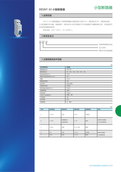
DZ267-32小型断路器
正泰-智慧能源解决方案提供商 l 028
小型断路器
DZ 267-32
壳架等级额定电流设计序号
塑料外壳式断路器
DZ267-32小型断路器(以下简称断路器)主要适用于交流50Hz ,额定电压230V ,额定电流至32A 的线路中作过载、短路保护,同时也可以在正常情况下作为线路的不频繁转换之用,尤其适用于住宅的照明配电系统。
符合标准:GB /T 10963.1、IEC 60898-1。
DZ267-32 小型断路器
终端电器
23.1 适用6mm 及以下铜导线连接(见表3),接线方法用螺钉拧紧接线,扭矩为1.5N·m。
3.2 脱扣特性曲线。
4.1 产品体积小,结构紧凑,18mm宽度内拥有1P+N两极,是DZ47两极产品体积的一半。
性价比优于同类产品。
4.2 产品壳体等塑料零件均采用高阻燃、耐高温、耐冲击塑料制成。
4.3 产品直接带零线安装,避免零线接线错误潜在的触电危险。
4.4 产品采用导轨安装,方便省时。
4.5 海拔高度:≤2000m 。
4.6 环境温度-5℃~+40℃,24h 内平均温度不超过35℃。
35
27
7.5
44±0.31
029 l 正泰-智慧能源解决方案提供商
小型断路器
6.1 产品型号和名称,如DZ267-32小型断路器。
6.2 瞬时脱扣型式和额定电流,如C20(照明保护型额定电流20A)。
6.3 订货数量,如500台。
6.4 订货举例:如DZ267-32小型断路器C20,500台。
正泰-智慧能源解决方案提供商 l 030。
SP5000 硬件手册说明书
SP5000系列 硬件手册SP5000-MM01-CS-PDF_K本文档中提供的信息包含有关此处所涉及产品之性能的一般说明和/或技术特性。
本文档并非用于 (也不代替) 确定这些产品对于特定用户应用场合的适用性或可靠性。
任何此类用户或设备集成商都有责任就相关特定应用场合或使用方面对产品执行适当且完整的风险分析、评估和测试。
Schneider Electric 或其任何附属机构或子公司 (以下简称Schneider Electric) 对于误用此处包含的信息而产生的后果概不负责。
如果您有关于改进或更正此出版物的任何建议、或者从中发现错误、请通知我们。
本手册可用于法律所界定的个人以及非商业用途。
在未获得施耐德电气书面授权的情况下,不得翻印传播本手册全部或部分相关内容、亦不可建立任何有关本手册或其内容的超文本链接。
施耐德电气不对个人和非商业机构进行非独占许可以外的授权或许可。
请遵照本手册或其内容原义并自负风险。
与此有关的所有其他权利均由施耐德电气保留。
在安装和使用本产品时、必须遵守国家、地区和当地的所有相关的安全法规。
出于安全方面的考虑和为了帮助确保符合归档的系统数据、只允许制造商对各个组件进行维修。
当设备用于具有技术安全要求的应用场合时、必须遵守有关的使用说明。
未能使用施耐德电气软件或认可的软件配合我们的硬件,则可能导致人身伤害、设备损坏或不正确的运行结果。
不遵守此信息可能导致人身伤害或设备损坏。
Copyright © 2019 Schneider Electric Japan Holdings Ltd。
保留所有权利。
2SP5000 系列 硬件手册目录安全信息. . . . . . . . . . . . . . . . . . . . . . . . . . . . . . . . . . . . . 7关于本书. . . . . . . . . . . . . . . . . . . . . . . . . . . . . . . . . . . . . 9第1章概述. . . . . . . . . . . . . . . . . . . . . . . . . . . . . . . . . . . . . . . . . 13型号配置 . . . . . . . . . . . . . . . . . . . . . . . . . . . . . . . . . . . . . . . . . . . . . . . 14型号. . . . . . . . . . . . . . . . . . . . . . . . . . . . . . . . . . . . . . . . . . . . . . . . . . . 15装箱物品 . . . . . . . . . . . . . . . . . . . . . . . . . . . . . . . . . . . . . . . . . . . . . . . 16认证与标准. . . . . . . . . . . . . . . . . . . . . . . . . . . . . . . . . . . . . . . . . . . . . . 18联邦通讯委员会射频干扰声明 - 适用于美国. . . . . . . . . . . . . . . . . . . . . 20危险位置安装 - 适用于美国和加拿大. . . . . . . . . . . . . . . . . . . . . . . . . . 21符合欧盟 (CE) 标准 . . . . . . . . . . . . . . . . . . . . . . . . . . . . . . . . . . . . . . . 23KC 标志. . . . . . . . . . . . . . . . . . . . . . . . . . . . . . . . . . . . . . . . . . . . . . . . 24无线 LAN 信息. . . . . . . . . . . . . . . . . . . . . . . . . . . . . . . . . . . . . . . . . . . 25第2章设备连接. . . . . . . . . . . . . . . . . . . . . . . . . . . . . . . . . . . . . 29系统设计 . . . . . . . . . . . . . . . . . . . . . . . . . . . . . . . . . . . . . . . . . . . . . . . 30附件. . . . . . . . . . . . . . . . . . . . . . . . . . . . . . . . . . . . . . . . . . . . . . . . . . . 32第3章部品标识及其功能. . . . . . . . . . . . . . . . . . . . . . . . . . . . . . 373.1主机模块 . . . . . . . . . . . . . . . . . . . . . . . . . . . . . . . . . . . . . . . . . . . . . . . 38标准主机模块. . . . . . . . . . . . . . . . . . . . . . . . . . . . . . . . . . . . . . . . . . . . 39增强型主机模块. . . . . . . . . . . . . . . . . . . . . . . . . . . . . . . . . . . . . . . . . . 41开放型主机模块. . . . . . . . . . . . . . . . . . . . . . . . . . . . . . . . . . . . . . . . . . 43LED 指示. . . . . . . . . . . . . . . . . . . . . . . . . . . . . . . . . . . . . . . . . . . . . . . 453.2显示模块 . . . . . . . . . . . . . . . . . . . . . . . . . . . . . . . . . . . . . . . . . . . . . . . 46精良显示 . . . . . . . . . . . . . . . . . . . . . . . . . . . . . . . . . . . . . . . . . . . . . . . 47高级显示模块. . . . . . . . . . . . . . . . . . . . . . . . . . . . . . . . . . . . . . . . . . . . 51LED 指示. . . . . . . . . . . . . . . . . . . . . . . . . . . . . . . . . . . . . . . . . . . . . . . 55第4章规格. . . . . . . . . . . . . . . . . . . . . . . . . . . . . . . . . . . . . . . . . 574.1一般规格 . . . . . . . . . . . . . . . . . . . . . . . . . . . . . . . . . . . . . . . . . . . . . . . 58规格电气 . . . . . . . . . . . . . . . . . . . . . . . . . . . . . . . . . . . . . . . . . . . . . . . 59规格环境 . . . . . . . . . . . . . . . . . . . . . . . . . . . . . . . . . . . . . . . . . . . . . . . 61结构规格 . . . . . . . . . . . . . . . . . . . . . . . . . . . . . . . . . . . . . . . . . . . . . . . 624.2功能规格 . . . . . . . . . . . . . . . . . . . . . . . . . . . . . . . . . . . . . . . . . . . . . . . 65显示规格 . . . . . . . . . . . . . . . . . . . . . . . . . . . . . . . . . . . . . . . . . . . . . . . 66存储器 . . . . . . . . . . . . . . . . . . . . . . . . . . . . . . . . . . . . . . . . . . . . . . . . . 67时钟. . . . . . . . . . . . . . . . . . . . . . . . . . . . . . . . . . . . . . . . . . . . . . . . . . . 68触摸屏 . . . . . . . . . . . . . . . . . . . . . . . . . . . . . . . . . . . . . . . . . . . . . . . . . 694.3接口规格 . . . . . . . . . . . . . . . . . . . . . . . . . . . . . . . . . . . . . . . . . . . . . . . 70接口规格 . . . . . . . . . . . . . . . . . . . . . . . . . . . . . . . . . . . . . . . . . . . . . . . 71接口连接 . . . . . . . . . . . . . . . . . . . . . . . . . . . . . . . . . . . . . . . . . . . . . . . 74用于 COM1/COM2 的串行接口 (RS-232C 和 RS-422/RS-485). . . . . . 77辅助输出/扬声器输出接口 (AUX). . . . . . . . . . . . . . . . . . . . . . . . . . . . . 80DVI-D 输出接口. . . . . . . . . . . . . . . . . . . . . . . . . . . . . . . . . . . . . . . . . . 813第5章尺寸 . . . . . . . . . . . . . . . . . . . . . . . . . . . . . . . . . . . . . . . . .835.1标准主机模块 . . . . . . . . . . . . . . . . . . . . . . . . . . . . . . . . . . . . . . . . . . . .84SP-5B00 . . . . . . . . . . . . . . . . . . . . . . . . . . . . . . . . . . . . . . . . . . . . . . .845.2增强型主机模块 . . . . . . . . . . . . . . . . . . . . . . . . . . . . . . . . . . . . . . . . . .85SP-5B10 . . . . . . . . . . . . . . . . . . . . . . . . . . . . . . . . . . . . . . . . . . . . . . .855.3开放型主机模块 . . . . . . . . . . . . . . . . . . . . . . . . . . . . . . . . . . . . . . . . . .86SP-5B40/SP-5B41. . . . . . . . . . . . . . . . . . . . . . . . . . . . . . . . . . . . . . . .865.4精良显示模块 . . . . . . . . . . . . . . . . . . . . . . . . . . . . . . . . . . . . . . . . . . . .87SP-5500TP. . . . . . . . . . . . . . . . . . . . . . . . . . . . . . . . . . . . . . . . . . . . . .88SP-5600TP/SP-5660TP. . . . . . . . . . . . . . . . . . . . . . . . . . . . . . . . . . . .89SP-5700TP. . . . . . . . . . . . . . . . . . . . . . . . . . . . . . . . . . . . . . . . . . . . . .90SP-5700WC. . . . . . . . . . . . . . . . . . . . . . . . . . . . . . . . . . . . . . . . . . . . .91SP-5800WC. . . . . . . . . . . . . . . . . . . . . . . . . . . . . . . . . . . . . . . . . . . . .925.5高级显示模块 . . . . . . . . . . . . . . . . . . . . . . . . . . . . . . . . . . . . . . . . . . . .93SP-5400WA. . . . . . . . . . . . . . . . . . . . . . . . . . . . . . . . . . . . . . . . . . . . .94SP-5500WA. . . . . . . . . . . . . . . . . . . . . . . . . . . . . . . . . . . . . . . . . . . . .95SP-5600WA. . . . . . . . . . . . . . . . . . . . . . . . . . . . . . . . . . . . . . . . . . . . .96SP-5600TA. . . . . . . . . . . . . . . . . . . . . . . . . . . . . . . . . . . . . . . . . . . . . .975.6主机模块和显示模块 - 组合尺寸. . . . . . . . . . . . . . . . . . . . . . . . . . . . . .98SP-5500TP 带主机模块 . . . . . . . . . . . . . . . . . . . . . . . . . . . . . . . . . . . .99SP-5600TP/SP-5660TP 带主机模块 . . . . . . . . . . . . . . . . . . . . . . . . . .101SP-5700TP 带主机模块 . . . . . . . . . . . . . . . . . . . . . . . . . . . . . . . . . . . .103SP-5700WC 带主机模块 . . . . . . . . . . . . . . . . . . . . . . . . . . . . . . . . . . .105SP-5800WC 带主机模块 . . . . . . . . . . . . . . . . . . . . . . . . . . . . . . . . . . .107SP-5400WA 带主机模块 . . . . . . . . . . . . . . . . . . . . . . . . . . . . . . . . . . .109SP-5500WA 带主机模块 . . . . . . . . . . . . . . . . . . . . . . . . . . . . . . . . . . .111SP-5600WA 带主机模块 . . . . . . . . . . . . . . . . . . . . . . . . . . . . . . . . . . .113SP-5600TA 带主机模块 . . . . . . . . . . . . . . . . . . . . . . . . . . . . . . . . . . . .115第6章安装和接线. . . . . . . . . . . . . . . . . . . . . . . . . . . . . . . . . . . .1176.1安装 . . . . . . . . . . . . . . . . . . . . . . . . . . . . . . . . . . . . . . . . . . . . . . . . . . .118安装步骤. . . . . . . . . . . . . . . . . . . . . . . . . . . . . . . . . . . . . . . . . . . . . . . .1186.2接线规则. . . . . . . . . . . . . . . . . . . . . . . . . . . . . . . . . . . . . . . . . . . . . . . .130连接 DC 电源线 . . . . . . . . . . . . . . . . . . . . . . . . . . . . . . . . . . . . . . . . . .131连接电源. . . . . . . . . . . . . . . . . . . . . . . . . . . . . . . . . . . . . . . . . . . . . . . .133接地 . . . . . . . . . . . . . . . . . . . . . . . . . . . . . . . . . . . . . . . . . . . . . . . . . . .1356.3USB 电缆紧固夹. . . . . . . . . . . . . . . . . . . . . . . . . . . . . . . . . . . . . . . . . .136A 型 USB 电缆夹 (1 个端口). . . . . . . . . . . . . . . . . . . . . . . . . . . . . . . . .137USB 电缆夹 mini-B (1 个端口) . . . . . . . . . . . . . . . . . . . . . . . . . . . . . . .1396.4AUX 接头 . . . . . . . . . . . . . . . . . . . . . . . . . . . . . . . . . . . . . . . . . . . . . . .141简介 . . . . . . . . . . . . . . . . . . . . . . . . . . . . . . . . . . . . . . . . . . . . . . . . . . .1416.5SD 卡插入/拔出 . . . . . . . . . . . . . . . . . . . . . . . . . . . . . . . . . . . . . . . . . .142简介 . . . . . . . . . . . . . . . . . . . . . . . . . . . . . . . . . . . . . . . . . . . . . . . . . . .143SD卡插入. . . . . . . . . . . . . . . . . . . . . . . . . . . . . . . . . . . . . . . . . . . . . . .144SD卡移除. . . . . . . . . . . . . . . . . . . . . . . . . . . . . . . . . . . . . . . . . . . . . . .145SD 卡备份 . . . . . . . . . . . . . . . . . . . . . . . . . . . . . . . . . . . . . . . . . . . . . .146 4SP5000 系列 硬件手册6.6CFast 卡 插入/移除 . . . . . . . . . . . . . . . . . . . . . . . . . . . . . . . . . . . . . . . 147简介. . . . . . . . . . . . . . . . . . . . . . . . . . . . . . . . . . . . . . . . . . . . . . . . . . . 148CFast卡插入 . . . . . . . . . . . . . . . . . . . . . . . . . . . . . . . . . . . . . . . . . . . . 149CFast卡移除 . . . . . . . . . . . . . . . . . . . . . . . . . . . . . . . . . . . . . . . . . . . . 150CFast 卡 数据备份. . . . . . . . . . . . . . . . . . . . . . . . . . . . . . . . . . . . . . . . 1516.7USB 前盖. . . . . . . . . . . . . . . . . . . . . . . . . . . . . . . . . . . . . . . . . . . . . . . 152打开 USB 前盖. . . . . . . . . . . . . . . . . . . . . . . . . . . . . . . . . . . . . . . . . . . 1526.8隔离设备和 USB/RS-422/485 转换适配器. . . . . . . . . . . . . . . . . . . . . . 154简介. . . . . . . . . . . . . . . . . . . . . . . . . . . . . . . . . . . . . . . . . . . . . . . . . . . 155安装到主机模块. . . . . . . . . . . . . . . . . . . . . . . . . . . . . . . . . . . . . . . . . . 156第7章维护. . . . . . . . . . . . . . . . . . . . . . . . . . . . . . . . . . . . . . . . . 159定期清洁 . . . . . . . . . . . . . . . . . . . . . . . . . . . . . . . . . . . . . . . . . . . . . . . 160定期检查事项. . . . . . . . . . . . . . . . . . . . . . . . . . . . . . . . . . . . . . . . . . . . 161更换防水橡皮垫圈 . . . . . . . . . . . . . . . . . . . . . . . . . . . . . . . . . . . . . . . . 162更换原电池. . . . . . . . . . . . . . . . . . . . . . . . . . . . . . . . . . . . . . . . . . . . . . 163更换系统卡 (SD 卡) . . . . . . . . . . . . . . . . . . . . . . . . . . . . . . . . . . . . . . . 166更换系统卡 (CFast 卡). . . . . . . . . . . . . . . . . . . . . . . . . . . . . . . . . . . . . 168更换背光灯. . . . . . . . . . . . . . . . . . . . . . . . . . . . . . . . . . . . . . . . . . . . . . 170售后服务 . . . . . . . . . . . . . . . . . . . . . . . . . . . . . . . . . . . . . . . . . . . . . . . 171567SP5000 系列 硬件手册安全信息重要信息声明在试图安装、操作、维修或维护设备之前,请仔细阅读下述说明并通过查看来熟悉设备。
DM432 低噪声数字式步进驱动器 说明书
深圳市雷赛机电技术开发有限公司地址:深圳市南山区登良路25号天安南油工业区二幢三楼邮编:518052电话:*************(20线)传真:*************Email:***************网址:上海办事处北京办事处地址:上海市淞江区九亭镇九新公路地址:北京市朝阳门广渠门外大街8号76号嘉和阳光大厦9楼优士阁B座308室电话:************/64853687电话:************传真:************传真:************美国雷赛科技公司香港雷赛科技公司Address: 630Parkland Dive 地址:沙田火炭山尾街 31-41号Rochester Hills, Mi48307 USA 华乐工业中心 E 座 9 字楼 3 室Tel:1-248-608-6388 电话:852-2952 9114852-2952 9395DM432低噪声数字式步进驱动器使用手册版权所有不得翻印【使用前请仔细阅读本手册,以免损坏驱动器】目录一、产品简介 (2)1. 概述 (2)2. 特点 (2)3. 应用领域 (2)二、电气、机械和环境指标 (2)1. 电气指标 (2)2. 使用环境及参数 (3)3. 机械安装图(单位:毫米) (3)4. 加强散热方式 (3)三、驱动器接口和接线介绍 (3)1. 接口描述 (3)2. 控制信号接口电路 (4)3. 控制信号时序图 (5)4. 控制信号模式设置 (5)5. 接线要求 (5)四、电流、细分拨码开关设定和参数自整定 (5)1.电流设定 (5)2. 细分设定 (6)3. 参数自整定功能 (6)五、供电电源选择 (6)六、电机选配 (6)1. 电机选配 (6)2. 电机接线 (7)七、典型接线案例 (7)八、保护功能 (8)九、常见问题 (8)1. 应用中常见问题和处理方法 (8)2. 驱动器常见问题答用户问 (9)雷赛产品保修条款 (9)DM432低噪声低发热数字式步进驱动器一、产品简介1. 概述DM432是雷赛公司新推出的数字式步进电机驱动器,采用最新32位DSP技术,用户可以设置256内的任意细分以及额定电流内的任意电流值,能够满足大多数场合的应用需要。
Z3032型 摇臂钻床使用说明书
摇臂钻床使用说明书
Z3032×10 Z3025×10A
摇臂钻床使用说明书..........................................................................................................................7 二 主要技术规格...............................................................................................................7 三 机床的搬运安装...........................................................................................................8
1 搬运.............................................................................................................................8 2 安装.............................................................................................................................8 四 机床的操纵.................................................................................................................12 1 主轴的起动...............................................................................................................12 2 主轴转速及进给量的变换.......................................................................................12 3 主轴的进给...............................................................................................................12 4 主轴箱和立柱的夹紧、松开...................................................................................12 5 摇臂夹紧、松开及升降...........................................................................................12 6 摇臂回转时应注意的问题.......................................................................................13 五 润滑.............................................................................................................................15 1 自动润滑...................................................................................................................15 2 人工润滑...................................................................................................................15 3 油箱的注油及排油...................................................................................................15 六 冷却.............................................................................................................................17 七 传动系统.....................................................................................................................17 八 电气.............................................................................................................................22 1 概述...........................................................................................................................22 2 电路说明...................................................................................................................22 3 照明的开闭...............................................................................................................23 4 机床的保护...............................................................................................................23 5 机床电源相序检查...................................................................................................24 6 电气设备的维护.......................................................................................................24 九 主要结构.....................................................................................................................29 1 主轴变速传动机构...................................................................................................29 2 主轴进给变速传动机构...........................................................................................30 3 主轴进给机构...........................................................................................................30 4 操纵机构...................................................................................................................31 5 主轴箱夹紧...............................................................................................................31 6 主轴及平衡...............................................................................................................31 7 立柱夹紧...................................................................................................................32 8 摇臂升降 ...................................................................................................................32 9 摇臂夹紧 ...................................................................................................................32 十 调整及维护.................................................................................................................32 1 机床的调整...............................................................................................................32 2 机床的维护...............................................................................................................34 十一 附件及易损件.........................................................................................................35 1 附件...........................................................................................................................35 2 易损件 .......................................................................................................................35
SYNTRON森创 DS20270H低压伺服驱动器使用手册说明书
DS20270H低压伺服驱动器使用手册版权声明安全有关的符号说明版权声明SYNTRON森创®是北京和利时电机公司(以下简称和利时电机)于2005年推出的产品品牌。
这个品牌浓缩了公司的核心技术和影响力,是公司始终注重自主创新,保持技术优势的体现。
说明书的内容参照了相关法律基准和行业基准。
如对本说明书提供的内容有疑问,请向销售人员咨询,致电客服热线,联系官网客服或致信本公司。
和利时电机保留在不事先通知的情况下,修改本手册中的产品和产品规格参数等权力。
手册请联系销售人员,或在和利时电机的官方网站下载相关手册。
和利时电机具有本产品及其软件的专利权、版权和其它知识产权。
未经授权,不得直接或者间接地复制、制造、加工、使用本产品及其相关部分。
和利时电机具有本使用说明书的著作权,未经许可,不得修改、复制使用说明书的全部或部分内容。
安全有关的符号说明本说明书中与安全有关的内容,使用了下述符号。
标注了安全符号的都为重要内容,请务必遵守。
安全注意事项注意事项⏹安全注意事项目录第一章产品概况与安装................................................................................ - 1 -1.1产品概况 .................................................................................................................. - 1 -1.2型号命名规则 .......................................................................................................... - 1 -1.3规格型号说明 .......................................................................................................... - 1 -1.4重量 .......................................................................................................................... - 1 -1.5安装尺寸 .................................................................................................................. - 2 -1.6性能参数 .................................................................................................................. - 3 -1.7产品组成 .................................................................................................................. - 3 -第二章配线 ................................................................................................. - 4 -2.1主回路端子的接线 .................................................................................................. - 4 -2.2编码器接口定义 ...................................................................................................... - 4 -2.3通讯接口定义 .......................................................................................................... - 5 -2.4CN3输入输出端子的管脚 ..................................................................................... - 5 -2.5驱动器外部接线图 .................................................................................................. - 6 -2.6脉冲指令输入接线图 .............................................................................................. - 7 -第三章试运行.............................................................................................. - 8 -3.1试运行基本流程 ...................................................................................................... - 8 -3.2内部速度模式空载试运行 ...................................................................................... - 9 -3.3位置模式空载试运行 .............................................................................................. - 9 -3.4驱动器调默认 .......................................................................................................... - 9 -3.5驱动器控制指示灯定义 .......................................................................................... - 9 -第四章参数与功能..................................................................................... - 10 -4.1Fn参数清单 .......................................................................................................... - 10 -4.1.1Fn参数位说明................................................................................................... - 10 -4.1.2Fn参数功能....................................................................................................... - 10 -4.2Dn参数清单 .......................................................................................................... - 15 -4.2.1Dn参数位说明 .................................................................................................. - 15 -4.2.2Dn参数功能 ...................................................................................................... - 15 -4.3Pn参数清单 .......................................................................................................... - 16 -4.3.1Pn参数位说明 .................................................................................................. - 16 -4.3.2Pn参数功能 ...................................................................................................... - 16 -第五章故障报警及处理.............................................................................. - 20 -5.1驱动器故障代码及解决方法 ................................................................................ - 20 -5.2电机故障现象及解决办法 .................................................................................... - 21 -产品概况与安装第一章产品概况与安装1.1 产品概况物流设备对体积的要求很严格,尤其对于两轮运行的场合,如何尽量缩小体积,同时实现两轮之间的精准运行及无差配合,DS系列二合一驱动器提供了最佳的解决方案。