Charge Transfer Induced Polarity Switching in Carbon Nanotube Transistors
碳纳米管-聚3,4-乙撑二氧噻吩修饰电极
南京 理 工大 学学报 ( 自然科 学版 ) Te Ju a oN mn n e i i c ad cnl y a r ! or lf a i U i rto S e e n n g v sy f c n ho g 【a 竺! o uJ
d a ruh essr c n igr ci t itr c ra ig - a e ab nn n t e ( WN s el o g hs u aea dbge t i ef eae.Snl w l dcro a o b s S T ) f a vy n a e l u
a e mo i e n t e s ra e o o d e e to e b h he c ls l— s e l t d.Th l cr d s r d f d o h u f c fg l lc r d y t e c mia e fa s mb y meho i e ee to e i
P l( , -tye e ix tip e e oy 3 4 eh l d0 yh0 h n ) n
C i n fi HE Ja — ,YE Xi — i e n xn,L U W e — n ,HE L i I nr g i e
( c ol f h m cl n ier g N S , aj g 0 4, hn ) S ho e ia E gnei , U T N ni 1 9 C ia oC n n 20
mV,t n l e rao tecci vh m t ( V) uv n rae ,a dteeet nf xo e h eco dae fh yl o a me y C creicess n l r u fh e s c r h co l t
单链DNA易位激发碳纳米管出现强电流
法 提升 千万倍 ,成 本 也将 大 大 降低 ,从 I 斫 实 现一对 一 的基 因测 序 ,为 完 善个 体 化 治 疗 以治愈 更多疾 病奠定 基础 。
米管 中 , 在 D A 分 子 携 带 的 负 电荷 的 N
・
译 自 Po.o SI o 95 r c f PEV l 7 } ,4 胡汉平 译 朱 海忱 校
单 链 D A 易 位 激 发 碳 纳 米 管 出现 强 电流 N
荚 科 学 家揭 乐 了单 链 D A 在 穿 越 N 碳 纳米 管 州发 生 的 “ 位 ” 过程 。这 一过 易 可 引发 电流 的不 规 则激 增 ,而 其 中 涉及
快 速测 序 的 关 键 在 于 对 D A 的 易 位 进 行 N 精确 控制 ,而碳 纳 米管 可 使对 纳 米 孔 特 性 的控制 变得更加 简易 、可 靠 。
林 赛 博士 强调 ,如果 能 进 一步 完 善 这
过程 ,D A测序 的速度 可 比使 用 现有 方 N
流被 导人 纳 米 管 时 ,由 6 0个 或 10个 核 2
的 电子 信号 特 性 ,或可 为 纳米 孔 技 术在 快 速 D A测序 中 的应 用 提供帮 助 。 N
美 国亚 利桑 那州 立 大 学生 物 设 计研 究
所 的斯 图尔 特 ・ 赛 博 士 及 同 事 在 《 林 科 学 》 杂 志上 发表 的此 项研 究 成果 借 助 了纳
米孔技 术 。纳米 孑 技术 是 近来 研 究 人员 在 L 微 制造 技术 上 的一 项 突破 ,可实 现 单个 分 子规格 内纳 米 孔 的构设 ,其 为单 分 子 的操 作 和研 究 提 供 了更 多 可 能 。科 学 家 表 示 ,
钴、氮共掺杂碳纳米复合材料的制备及其在锂硫电池中的应用
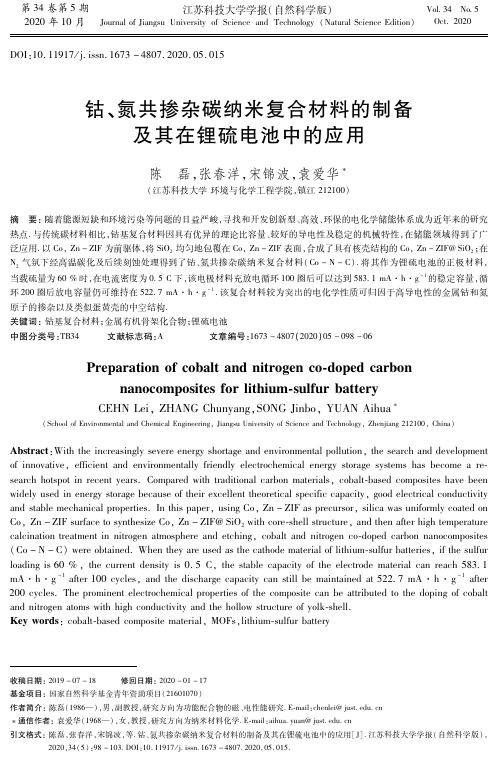
第34卷第5期2020年10月 江苏科技大学学报(自然科学版)JournalofJiangsuUniversityofScienceandTechnology(NaturalScienceEdition) Vol 34No 5Oct.2020 DOI:10.11917/j.issn.1673-4807.2020.05.015钴、氮共掺杂碳纳米复合材料的制备及其在锂硫电池中的应用陈 磊,张春洋,宋锦波,袁爱华(江苏科技大学环境与化学工程学院,镇江212100)摘 要:随着能源短缺和环境污染等问题的日益严峻,寻找和开发创新型、高效、环保的电化学储能体系成为近年来的研究热点.与传统碳材料相比,钴基复合材料因具有优异的理论比容量、较好的导电性及稳定的机械特性,在储能领域得到了广泛应用.以Co,Zn-ZIF为前驱体,将SiO2均匀地包覆在Co,Zn-ZIF表面,合成了具有核壳结构的Co,Zn-ZIF@SiO2;在N2气氛下经高温碳化及后续刻蚀处理得到了钴、氮共掺杂碳纳米复合材料(Co-N-C).将其作为锂硫电池的正极材料,当载硫量为60%时,在电流密度为0 5C下,该电极材料充放电循环100圈后可以达到583 1mA·h·g-1的稳定容量,循环200圈后放电容量仍可维持在522 7mA·h·g-1.该复合材料较为突出的电化学性质可归因于高导电性的金属钴和氮原子的掺杂以及类似蛋黄壳的中空结构.关键词:钴基复合材料;金属有机骨架化合物;锂硫电池中图分类号:TB34 文献标志码:A 文章编号:1673-4807(2020)05-098-06收稿日期:2019-07-18 修回日期:2020-01-17基金项目:国家自然科学基金青年资助项目(21601070)作者简介:陈磊(1986—),男,副教授,研究方向为功能配合物的磁、电性能研究.E mail:chenlei@just.edu.cn 通信作者:袁爱华(1968—),女,教授,研究方向为纳米材料化学.E mail:aihua.yuan@just.edu.cn引文格式:陈磊,张春洋,宋锦波,等.钴、氮共掺杂碳纳米复合材料的制备及其在锂硫电池中的应用[J].江苏科技大学学报(自然科学版),2020,34(5):98-103.DOI:10.11917/j.issn.1673-4807.2020.05.015.Preparationofcobaltandnitrogenco dopedcarbonnanocompositesforlithium sulfurbatteryCEHNLei,ZHANGChunyang,SONGJinbo,YUANAihua(SchoolofEnvironmentalandChemicalEngineering,JiangsuUniversityofScienceandTechnology,Zhenjiang212100,China)Abstract:Withtheincreasinglysevereenergyshortageandenvironmentalpollution,thesearchanddevelopmentofinnovative,efficientandenvironmentallyfriendlyelectrochemicalenergystoragesystemshasbecomearesearchhotspotinrecentyears.Comparedwithtraditionalcarbonmaterials,cobalt basedcompositeshavebeenwidelyusedinenergystoragebecauseoftheirexcellenttheoreticalspecificcapacity,goodelectricalconductivityandstablemechanicalproperties.Inthispaper,usingCo,Zn-ZIFasprecursor,silicawasuniformlycoatedonCo,Zn-ZIFsurfacetosynthesizeCo,Zn-ZIF@SiO2withcore shellstructure,andthenafterhightemperaturecalcinationtreatmentinnitrogenatmosphereandetching,cobaltandnitrogenco dopedcarbonnanocomposites(Co-N-C)wereobtained.Whentheyareusedasthecathodematerialoflithium sulfurbatteries,ifthesulfurloadingis60%,thecurrentdensityis0.5C,thestablecapacityoftheelectrodematerialcanreach583 1mA·h·g-1after100cycles,andthedischargecapacitycanstillbemaintainedat522 7mA·h·g-1after200cycles.Theprominentelectrochemicalpropertiesofthecompositecanbeattributedtothedopingofcobaltandnitrogenatomswithhighconductivityandthehollowstructureofyolk shell.Keywords:cobalt basedcompositematerial,MOFs,lithium sulfurbattery 为了满足日益增长的能源需求和大型储能设备市场的应用,人们对长寿命、高能量密度的可充电锂离子电池(LIBs)提出了更高的要求.在各类可充电电池系统中,锂硫电池因其高理论容量(1675mA·h·g-1)和能量密度(2600W·h·kg-1)而备受关注[1].在锂电池材料中,硫正极材料的含量丰富、成本低廉和环保型使LIBs在商业上具有更大的竞争力.但是,锂硫电池具有低实际容量、快速的容量衰减和低库仑效率等缺点.另外,硫及其放电产物的绝缘性会限制了硫的电化学利用,而且生成的中间多硫化物容易扩散到电解液中,导致绝缘性差以及较低的硫的利用率,从而在充放电过程中产生穿梭效应[2].为了解决上述问题,国内外研究者采取了各种方法来减少穿梭效应,包括开发正极材料、电解质和保护阳极的思路,以提高锂电池的整体性能.目前最有前景的方法是将硫与各种多孔碳基质高效结合,包括微/介孔碳、多孔空心碳纳米球、碳纳米纤维/纳米管和石墨烯等.具有高表面积的多孔碳可以提供大的孔体积来封装硫和作为电子传输的导电网络将多硫化物中间产物困与孔内.文献[3]使用ZIF-8衍生的微孔碳多面体作为载硫基质,其初始容量高达1500mA·h·g-1.文献[4]通过在氧化石墨烯上原位生长ZIF-8和ZIF-67,在高温处理后形成氮掺杂多孔碳/石墨烯(NPC/G)混合物.高导电石墨烯不仅提供了一个相互连接的导电框架,以促进快速的电子传输,而且作为一个建筑单元以支撑金属有机骨架材料(MOF)衍生的碳.由于多孔碳具有丰富的孔结构和氮掺杂特性,使其对多硫化物具有物理限制和化学吸附两种性质.将其作为锂硫电池正极材料,循环超过300次仍能维持良好的稳定性,比容量高达1372mA·h·g-1,说明MOF衍生碳材料和石墨烯复合结构的设计可以提高锂硫电池的电性能.最近有报道称,导电金属具有高效的聚硫介质,能够影响表面聚硫穿梭过程,从而增强氧化还原化活性.因此当导电金属被用于锂硫电池时具有较好的循环稳定性.文献[5]合成了一种含有钴和氮掺杂石墨碳的ZIF-67衍生硫宿主,作为高效基质来截存多硫化物,在大电流下500圈循环后仍具有良好的循环稳定性.文献[6]通过回流法制备了新型双金属Zn,Co-MOF-5,将其碳化转化为具有较大表面积的钴@石墨碳多孔复合材料(Co@GC-PC).Co@GC-PC具有较大的表面积和足够的介孔,使其能够吸附多硫化物,而电子传导则来源于分布良好的钴和石墨碳.密度泛函理论计算也进一步表明,钴单质促进了硫化物的分解.当其作为硫的载体时,在0 2C(1C=1675mA·h·g-1)的电流密度下,经过220圈循环后仍能维持高可逆容量(790mA·h·g-1).文中利用Co,Zn-ZIF前驱体和二氧化硅保护煅烧策略合成了钴、氮共掺杂碳纳米复合材料(Co-N-C).在合成的过程中(图1),先将Co,Zn-ZIF前驱体表面包覆二氧化硅后再进行高温热解,在氮气氛围下高温(900℃)碳化处理,单质锌将随之挥发.同时,其包覆MOF的方法可以有效防止高温条件下产物的聚集.最后,通过氢氟酸刻蚀表面的二氧化硅和裸露在外面未被保护的钴单质,进而制备Co-N-C并将该材料作为硫的载体.S/Co-N-C的复合物在应用为锂硫电池的正极材料时,显示出优异的电化学性能.图1 基于SiO2保护煅烧策略的Co-N-C合成示意Fig.1 SyntheticprocedureoftheCo-N-CbytheSiO2-protectedcalcinationstrategy1 实验1 1 试剂硝酸钴,硝酸锌,2-甲基咪唑,无水甲醇,十六烷基三甲基溴化铵,硅酸四乙酯(上海萨恩化学技术有限公司,分析纯);氢氧化钠,氢氟酸,无水乙醇(国药集团有限公司,分析纯);聚偏氟乙烯(PVDF);双三氟甲基磺酸亚酰胺锂(LiTFSI);去离子水.1 2 材料制备1 2 1 Co,Zn-ZIF的合成将16mmol的Co(NO3)2·6H2O和16mmol的Zn(NO3)2·6H2O溶解在200mL的无水甲醇中,将128mmol的2-甲基咪唑溶解于200mL的无水甲醇中,分别搅拌30min.然后将金属盐溶液缓慢添加到2-甲基咪唑溶液中,室温搅拌4h.通过离心收集产物并用无水甲醇清洗.1 2 2 Co,Zn-ZIF@SiO2的合成将所得样品(300mg)超声分散在120mL的H2O中,搅拌30min后加入75mg的十六烷基三甲基溴化铵和30mg的氢氧化钠.然后继续搅拌30min,将0 6mL的硅酸四乙酯逐滴加入上述溶液中,反应1h后迅速离心.产物用水和无水乙醇99第5期 陈磊,等:钴、氮共掺杂碳纳米复合材料的制备及其在锂硫电池中的应用分别清洗3次.1 2 3 Co-N-C的合成将干燥好的样品置于管式炉中,在氮气氛围下,以1℃/min的加热速率缓慢升至900℃并维持4h.将所得到的黑色产物Co-N-C@SiO2超声分散在氢氟酸(5%)的水溶液中刻蚀6h,用来去除二氧化硅以及表面未被保护的钴单质.用大量的水和无水乙醇润洗Co-N-C,抽滤至中性,烘干待用.1 2 4 S/Co-N-C的合成将Co-N-C与硫单质按质量比4∶6进行混合,在玛瑙研钵中充分研磨30min使其混合均匀,然后转移至密闭的小瓶中155℃加热12h,获得S/Co-N-C.1 3 材料表征采用X射线衍射仪(XRD,Cu靶(λ=1 5418),U=40kV,I=30mA)测定产物的物质结构,扫描角度为10~80°之间,扫率为5°/min.用场发射扫描电子显微镜(SEM)和透射电子显微镜(TEM)分别观察表面形貌和微观结构.X射线光电子能谱(XPS)用来分析样品组成和价态结构.使用热重分析仪器(TG)分析产物的热分解行为,测试温度为室温~600℃之间,升温速度10℃/min,在氮气氛围下进行.1 4 电化学性能测试将S/Co-N-C样品与科琴黑和PVDF在8∶1∶1的质量比混合均匀,与N-甲基吡咯烷酮(NMP)为分散剂,混合成粘度适当的浆料.随后把浆料均匀的涂在铝箔上,并在真空干燥箱中55℃下干燥.利用打孔机将铝箔裁成圆片电极( =12mm),组装成纽扣式半电池,该半电池组装在充满氩气的手套箱中,水和氧浓度均低于1×10⁻⁶.以金属锂作为对电极,Celgard2400薄膜作为隔膜,电解液由1 0mol/LLiTFSI的乙二醇二甲醚(DME)和1,3-二氧戊环(DOL)溶液组成(体积比为1∶1,其中含有0 2%的添加剂LiNO3).将组装完的电池静置16h后待测,在1 7~2 8V(相对于Li/Li+)的电压范围内,通过蓝电测试系统(LANDCT-2001A)进行恒流充放电测试.所有的容量都是根据正极材料的硫质量来计算.2 结果与讨论2 1 Co-N-C和S/Co-N-C的物相与结构分析 图2为Co,Zn-ZIF和Co,Zn-ZIF@SiO2的XRD图谱.Co,Zn-ZIF的特征峰比较尖锐,表明成功合成了高结晶度的MOF,与文献[7]报道的图谱相吻合.经过正硅酸四乙酯在碱性条件下的水解缩合,由图可以看出包覆完二氧化硅后的XRD图仍呈现的是Co,Zn-ZIF的衍射峰,这主要是由于二氧化硅是无定型材料.图3为单质硫、Co-N-C以及S/Co-N-C的XRD图谱.Co-N-C的衍射峰在2θ=26°和45°处有两个明显的宽峰,对应于石墨碳的(002)和(100)晶面[8].S/Co-N-C和单质硫具有相同的物相,复合物中所有的衍射峰与单质硫粉的衍射峰相匹配.图2 Co,Zn-ZIF与Co,Zn-ZIF@SiO2的XRD图谱Fig.2 XRDpatternsofCo,Zn-ZIFandCo,Zn-ZIF@SiO2图3 单质硫粉、Co-N-C以及S/Co-N-C的XRD图谱Fig.3 XRDpatternsofsulfur,Co-N-CandS/Co-N-C图4为所制备样品的扫描电镜和透射电镜图片以及元素分析.图4 样品的扫描电镜和透射电镜图片以及元素分析Fig.4 SEMandTEMimagesofthesamplesandtheelementalmappingdistributionofS/Co-N-C如图4(a)中,Co,Zn-ZIF显示出均匀的菱形多面体形貌和光滑的颗粒表面.从透射图片(图4(b))可以看出其平均尺寸约为100nm.通过二氧001江苏科技大学学报(自然科学版)2020年化硅的包覆之后,Co,Zn-ZIF@SiO2没有发生结构的变化,仍然维持着原有的颗粒感,显示出核壳结构且表面趋于球形形貌,外壳的厚度约为10nm(图4(c)、(d)和(f)).随后在惰性气体下高温碳化和刻蚀后将Co,Zn-ZIF@SiO2转化为Co-N-C,由图4(e)的扫描图片可以看出前驱体经过煅烧处理以及除去二氧化硅后保持着较好的分散性且大小均一.从图4(f)的透射电镜图像可以看出Co-N-C仍保持完整的Co,Zn-ZIF骨架结构.值得注意的是该材料转化为类似蛋黄壳结构,这种中空结构更有利于较大的体积进行载硫,其平均粒径约为100nm.图4(g)是S/Co-N-C的元素分布图,从图中可以看出该样品均匀分布着C、Co、N、S4种元素,进一步证实成功制备了该复合材料.利用X射线光电子能谱(XPS)分析了S/Co-N-C的表面化学组成.从全谱图中(图5(a))表明主要元素为钴、氧、氮、碳、硫.钴的特征峰并不是很清晰,这是由于大部分钴都处于碳基体的内部且含量较少.Co2p的精细谱中位于780 8eV和795 9eV处的两个特征峰归因于金属钴[9],如图5(b).图5(c)中N1s的精细谱可分成3个组分,包括吡啶氮(398 5eV)、吡咯氮(400 0eV)、石墨化氮(400 7eV),其中吡咯型氮和吡啶型氮主要的作用来束缚多硫化锂来减小穿梭效应,进而提高锂硫电池的性能[10].S2p通过分峰拟合可以分成3个峰(图5(d)),S2p3/2和S2p1/2的组分与S-S物种的存在有关,它们的结合能分别为163 8eV和165 0eV.168 6eV处出现的宽峰与硫酸盐物种有关[11-12].图5 S/Co-N-C的XPS图谱Fig.5 XPSspectraoftheS/Co-N-C图6为S/Co-N-C复合材料在氮气氛围下,以10℃/min的加热速率下所测试的热重曲线.从图可以看出在150~280℃之间有着明显的质量损失,这主要归因于大孔和表面硫的蒸发.在280~400℃之间也有较小的质量损失平台,这主要是由于内部或者较小孔内硫分子的蒸发.数据结果进一步表明其载硫量为60%[13].图6 S/Co-N-C复合材料的热重曲线Fig.6 TGAcurveofS/Co-N-Ccomposites2 2 电化学性能分析将S/Co-N-C复合材料作为锂硫电池的正极材料,平均载硫量为1 2mg·cm-2,组装成纽扣式半电池对其进行相应的电化学性能测试,如图7.图7 S/Co-N-C复合材料的电化学性能Fig.7 ElectrochemicalpropertiesofthecompositesofS/Co-N-C101第5期 陈磊,等:钴、氮共掺杂碳纳米复合材料的制备及其在锂硫电池中的应用图7(a)为电压区间在1 7~2 8V,电流密度为0 5C(1C=1675mA·h·g-1)时,电极材料的循环性能图.结果表明,S/Co-N-C展现了优异的循环稳定性,当其载硫量为60%时,该正极材料可提供高达803 9mA·h@g-1的初始可逆容量,100圈充放电循环之后仍能维持583 1mA·h·g-1的稳定容量,循环200圈后放电比容量可以达到522 7mA·h·g-1.该正极材料的每圈容量衰减在0 17%左右,可逆容量不可避免的衰减主要是由于穿梭效应.为了进一步评估该电极材料的电化学性能,也对其在不同电流密度下进行了倍率性能的测试(图7(b)).S/Co-N-C在0 1C的电流密度下可提供高达1265 7mA·h·g-1的放电比容量,第二圈略有下降至1072 5mA·h·g-1.在电流密度增加至0 2C、0 5C、1 0C、2 0C时,电极材料的可逆容量分别为804 2mA·h·g-1、693 5mA·h·g-1、601 5mA·h·g-1、525 5mA·h·g-1.当电流密度降至0 2C下,循环50圈后,其放电比容量可恢复至787 7mA·h·g-1.从结果可以发现该材料在不同电流密度下均表现出良好的电化学稳定性.图7(c)是电压窗口为1 7~2 8V,大电流密度为0 5C时,前三圈的充放电曲线图,用来分析该正极材料在充放电过程的电化学反应.首圈充放电时放电平台与后两圈的平台存在较大的差异,这是在第一次充放电过程中正极材料存在比较大的极化现象,之后的两圈充放电时极化反应减小,可以看到随后两圈的放电曲线也恢复至正常的平台.第二圈的放电曲线显示出典型的两个平台,分别处于2 3V和2 1V[14].在2 3V的电压平台与S8向可溶性长链多硫化物(Li2Sn,4≤n≤8)的转变有关,而在2 1V的电压平台则与可溶性长链Li2Sn进一步还原为不溶性短链多硫化物(Li2Sn,n<4)相对应[15-16].另外,第二圈充电曲线平台与上述相反的形式有关,代表着多硫化物向硫转变的过程[17].尽管在0 5C的大电流密度下,第二圈和第三圈的充放电曲线较好的重合且平台清晰可见,说明该材料的优异循环稳定性[18].锂硫电池中低的硫含量会展现出较高的放电比容量,然而极片的载硫量小于2mg/cm2会降低其实际能量密度[19].考虑到高面积容量对于锂硫电池实际应用的重要性,文中也探究了高载硫量电极的循环性能,如图8.将S/Co-N-C材料涂覆成厚膜电极(载硫量约2 4mg/cm2),在0 1C电流密度下循环100圈后其放电比容量为350 4mA·h·g-1,将电流密度增至0 2C再循环100圈后放电比容量仍能达到278 4mA·h·g-1.S/Co-N-C正极材料的优良电化学性能主要是由于其特殊的组分和结构.首先,嵌入的钴纳米粒子提供了吸附多硫化物的强相互作用,可大大提高多硫化物的氧化还原反应动力学.其次,类似蛋黄壳的中空结构对于硫的大装载率的包封和物理约束很有效.最后,氮掺杂碳具有高导电性,能够高效的束缚多硫化锂的溶出,减小穿梭效应,从而提高硫的利用率,进一步稳定锂硫电池的电化学循环性能和高比容量.图8 在0 1C和0 2C的电流密度下,载硫量为2 4mg/cm2的循环性能Fig.8 Cyclingperformanceof2 4mg/cm2sulfurloadingatcurrentdensitiesof0 1Cand0 2C3 结论以双金属Co,Zn-ZIF为前驱体,通过高温碳化和刻蚀工艺合成了类似蛋黄壳中空结构的Co-N-C复合材料.将其作为高性能锂硫电池载硫体,S/Co-N-C由于合理的纳米结构和组分,具有很高的可逆比容量,良好的倍率性能和超长的循环稳定性.值得注意的是,S/Co-N-C正极材料(高面积载硫量为2 4mg·cm-2)在200圈后仍显示出稳定的循环性能.在该工作中,金属源和氮掺杂的碳材料有利于提高复合材料的导电性,而中空的结构则有利于存储单质硫和缓冲体积的膨胀,为获得高性能锂硫电池提供了新的思路.参考文献(References)[1] LIZhen,ZHANGJintao,GUANBuyuan,etal.Asulfurhostbasedontitaniummonoxide@carbonhollowspheresforadvancedlithium sulfurbatteries[J].Na tureCommunications,2016(7):13065-13076.DOI:10.1038/ncomms13065.[2] BAOWZ,LIUL,WANGCY,etal.Facilesynthesisofcrumplednitrogen dopedmxenenanosheetsasanewsulfurhostforlithium sulfurbatteries[J].Ad201江苏科技大学学报(自然科学版)2020年vancedEnergyMaterials,2018,8(13):1702485.DOI:10.1002/aenm.201702485.[3] LIXX,ZHENGSS,JINL,etal.Metal organicframework derivedcarbonsforbatteryapplications[J].AdvancedEnergyMaterials,2018,8(23):1800716.DOI:10.1002/aenm.201800716.[4] CHENK,SUNZH,FANGRP,etal.Metal OrganicFrameworks(MOFs) derivednitrogen dopedporouscarbonanchoredongraphenewithmultifunctionaleffectsforlithium sulfurbatteries[J].AdvancedFunctionalMaterials,2018,28(38):1707592.DOI:10.1002/adfm.201707592.[5] LIYJ,FANJM,ZHENGMS,etal.Anovelsyner gisticcompositewithmulti functionaleffectsforhighperformanceLi-Sbatteries[J].Energy&EnvironmentalScience,2016,9(6):1998-2004.DOI:10.1039/C6EE00104A.[6] LUYQ,WUYJ,SHENGT,etal.NovelsulfurhostcomposedofcobaltandporousgraphiticcarbonderivedfromMOFsforthehigh performanceLi-Sbattery[J].ACSAppliedMaterials&Interfaces,2018,10(16):13499-13508.DOI:10.1021/acsami.8b00915.[7] SHANGL,YUHJ,HUANGX,etal.Well dispers edZIF derivedCo,N-Co-dopedcarbonnanoframesthroughmesoporous silica protectedcalcinationasefficientoxygenreductionelectrocatalysts[J].AdvancedMaterials,2016,28(8):1668-1674.DOI:10.1002/adma.201505045.[8] LIJ,CHENC,QINFR,etal.MesoporousCo-N-Ccompositeasasulfurhostforhigh capacityandlonglifelithium sulfurbatteries[J].JournalofMaterialsScience,2018,53(18):13143-13155.DOI:10.1007/s10853-018-2566-z.[9] BAIQ,SHENFC,LISL,etal.Cobalt@Nitrogen dopedporouscarbonfiberderivedfromtheelectrospunfiberofbimetal organicframeworkforhighlyactiveoxygenreduction[J].SmallMethods,2018,2(12):1800049.DOI:10.1002/smtd.201800049.[10] CHENGXL,LIDJ,LIUFF,etal.Bindingnanos izedcobaltchalcogenidesinB,N codopedgrapheneforenhancedsodiumstorage[J].SmallMethods,2018,3(4):1800170.DOI:10.1002/smtd.201800170.[11] ZHANGJH,HUANGM,XIBJ,etal.Systematicstudyofeffectonenhancingspecificcapacityandelectrochemicalbehaviorsoflithium sulfurbatteries[J].AdvancedEnergyMaterials,2018,8(2):1701330.DOI:10.1002/aenm.201701330.[12] CHENT,CHENGBR,ZHUGY,etal.Highlyeffi cientretentionofpolysulfidesin“seaurchin” likecarbonnanotube/nanopolyhedrasuperstructuresascathodematerialforultralong lifelithium sulfurbatteries[J].NanoLetters,2017,17(1):437-444.DOI:10.1021/acs.nanolett.6b04433.[13] YEC,ZHANGL,GUOCX,etal.A3Dhybridofchemicallycouplednickelsulfideandhollowcarbonspheresforhighperformancelithium sulfurbatteries[J].AdvancedFunctionalMaterials,2017,27(33):1702524.DOI:10.1002/adfm.201702524.[14] JIANGHQ,LIUXC,WUYS,etal.Metal OrganicFrameworksforhighcharge dischargeratesinlithiumsulfurbatteries[J].AngewandteChemieInternationalEdition,2018,57(15):3916-3921.DOI:10.1002/anie.201712872.[15] MANOJM,JASNAM,ANILKUMARKM,etal.Sulfur polyanilinecoatedmesoporouscarboncompositeincombinationwithcarbonnanotubesinterlayerasasuperiorcathodeassemblyforhighcapacitylithiumsulfurcells[J].AppliedSurfaceScience,2018,458:751-761.DOI:10.1016/j.apsusc.2018.07.113.[16] QUYH,ZHANGZA,WANGXW,etal.AsimpleSDS assistedself assemblymethodforthesynthesisofhollowcarbonnanospherestoencapsulatesulfurforadvancedlithium sulfurbatteries[J].JournalofMaterialsChemistryA,2013,1(45):14306-14310.DOI:10.1039/C3TA13306K.[17] ZHANGJT,LIZ,CHENY,etal.Nickel ironlay ereddoublehydroxidehollowpolyhedronsasasuperiorsulfurhostforlithium sulfurbatteries[J].AngewChemIntEdEngl,2018,57(34):10944-10948.DOI:10.1002/anie.201805972.[18] CHENT,ZHANGZW,CHENGBR,etal.Self templatedformationofinterlacedcarbonnanotubesthreadedhollowCo3S4nanoboxesforhigh rateandheat resistantlithium sulfurbatteries[J].JournaloftheAmericanChemicalSociety,2017,139(36):12710-12715.DOI:10.1021/jacs.7b06973.[19] HEJR,CHENYF,MANTHIRAMA.MOF derivedcobaltsulfidegrownon3Dgraphenefoamasanefficientsulfurhostforlong lifelithium sulfurbatteries[J].Science,2018,4:36-43.DOI:10.1016/j.isci.2018.05.005.(责任编辑:顾琳)301第5期 陈磊,等:钴、氮共掺杂碳纳米复合材料的制备及其在锂硫电池中的应用。
姜雪峰论文

低温制备碳纳米管的探索学院:理学院专业:物理学(师范类)学生姓名:姜雪峰学号:1011127027指导教师:孙艳中文摘要碳纳米管作为一维纳米材料,重量轻,六边形结构连接完美,具有许多异常的力学、电学和化学性能。
近些年随着碳纳米管及纳米材料研究的深入其广阔的应用前景也不断地展现出来。
碳纳米管,又名巴基管,是一种具有特殊结构(径向尺寸为纳米量级,轴向尺寸为微米量级,管子两端基本上都封口)的一维量子材料。
碳纳米管主要由呈六边形排列的碳原子构成数层到数十层的同轴圆管。
层与层之间保持固定的距离,约0.34nm,直径一般为2~20 nm。
并且根据碳六边形沿轴向的不同取向可以将其分成锯齿形、扶手椅型和螺旋型三种。
其中螺旋型的碳纳米管具有手性,而锯齿形和扶手椅型碳纳米管没有手性。
英文摘要目录第一章引言 (1)1.1碳纳米管的背景意义 (1)1.2碳纳米管的研究现状 (2)1.3.碳纳米管的分类............................................................................................ 1.4碳纳米管的结构特征....................................................................................第二章.碳纳米管的制备方法 ........................................................ 2.1催化裂解法.................................................................................................... 2.2石墨电弧放电法............................................................................................ 2.3化学气相沉积法............................................................................................ 2.4水热法............................................................................................................ 2.5凝聚相电解生成法........................................................................................ 2.6等离子体增强化学气相沉积法(PECVD法).........................................第三章如何利用PECVD探索低温制备碳纳米管123.1探索低温制备碳纳米管的实验条件............................................................ 3.2PECVD低温制备碳纳米管的方法步骤......................................................第一章引言1.1碳纳米管的背景意义1.碳纳米管1991年开始被发现,自那以后引起了世界大多数科学家的兴趣及关注。
有机场效应晶体管-2014

Current (I)voltage (V) characteristics, at VG
测定迁移率的公式: ID=(W/L) Ci µ (VG﹣VT)VD (linear) ID=(W/2L) Ci µ (VG﹣VT)2 (saturation)
载流子迁移率的测试方法:飞行时间法(TOF)
d
t
寡聚噻吩、硒吩衍生物
噻吩芳环寡聚衍生物
有机场效应晶体管:p型小分子材料
硫族杂稠环衍生物
有机场效应晶体管:p型小分子材料
四硫富瓦烯衍生物 含氮杂稠环衍生物
有机场效应晶体管:p型小分子材料
酞菁卟啉衍生物 其它p型小分子材料
有机场效应晶体管:n型小分子材料
含氟n型小分子材料 酸酐酰亚胺n型小分子材料
有机场效应晶体管
苏仕健 mssjsu@
华南理工大学 高分子光电材料与器件研究所
世界第一台计算机
生日:1946年2月14日 姓名:电子数值积分和计算机(Electronic Numerical Integrator And Computer,ENIAC) 父母:美国陆军军械部、美国宾夕法尼亚 大学莫尔学院 组成:17468个电子管、6万个电阻器、1万 个电容器和6千个开关,重30吨,占地160 平方米,耗电174千瓦,耗资45万美元。 运算能力:5千次加法或400次乘法运算/秒
-5
-30 V
-5
-80 V
-5
-20 V
-5
-5
-60 V
-5
-6
-10 V 0V
0.0 0 -20 -40 -60 -80
-40 V -20 V 0V
0.0 0 -10 -20 -30 Drain voltage (V) -40
The Physical Properties of Carbon Nanotubes

The Physical Properties of CarbonNanotubesCarbon nanotubes (CNTs) are one of the most fascinating materials developed in the past few decades. They are cylindrical nanostructures composed of carbon atoms arranged in a hexagonal pattern. CNTs have unique properties, including high strength and stiffness, small size, exceptional electrical conductivity, and thermal conductivity. These properties make them preferable for numerous applications in several fields, including electronics, materials science, aerospace, and biotechnology.Structure of carbon nanotubesCarbon nanotubes have two primary structural types: single-walled nanotubes (SWNTs) and multi-walled nanotubes (MWNTs). SWNTs consist of a single rolled sheet, while MWNTs contain multiple rolled sheets. The diameter of SWNTs ranges from 0.4to 2 nm, while MWNTs have diameters ranging from 2 to 100 nm. The length of CNTs is usually several micrometers, but they can be longer.Thanks to their small dimensions and tubular structure, CNTs have a high aspect ratio, which means that their length is much greater than their diameter. This aspect ratio gives CNTs their unique mechanical properties. They are exceptionally strong and stiff, with a Young's modulus three to four times higher than that of steel. Moreover, CNTs are quite resilient, and their deformation before failure is much more elevated than conventional materials, making them perfect for use in new structural materials.Electrical properties of carbon nanotubesOne of the most remarkable properties of CNTs is their electrical conductivity. They have excellent electrical properties, which means they can conduct electricity even better than copper. SWNTs are metallic or semiconducting depending on their chiral angle, while MWNTs are usually metallic.SWNTs have particular band structures, and their electrical properties depend heavily on their atomic structure. The electronic properties of CNTs make them ideal for use in electronic applications, such as field-effect transistors, diodes, and sensors. CNTs have the potential to improve the performance of transistors and other electronic devices significantly.Thermal properties of carbon nanotubesCNTs also have exceptional thermal conductivity, making them useful in thermal management materials. The thermal conductivity of CNTs is approximately seven times higher than that of copper. Moreover, CNTs are excellent heat conductors at the nanoscale, which gives them the potential to improve the efficiency of thermal management materials in electronic devices.Other physical properties of carbon nanotubesIn addition to their excellent mechanical, electrical, and thermal properties, CNTs also exhibit some other unique physical properties that make them advantageous for several applications. They are lightweight and can be dispersed in solvents, allowing them to be used in coatings, composites, and other materials.Furthermore, because of their nanoscale dimensions, CNTs have a high surface area-to-volume ratio, which makes them an effective adsorbent for gas and liquid molecules. This property makes CNTs promising candidates for gas storage and separation, as well as water purification.ConclusionCNTs are exceptional materials that have unique physical properties that lend themselves to several applications. They are lightweight, strong, stiff, and excellent electrical and thermal conductors, making them preferable for use in several fields, including electronics, materials science, and aerospace. Their physical properties make CNTs promising candidates for improving the performance of electronic devices, structural materials, and energy storage systems.。
微波场作用下碳纳米管量子点耦合器件的介观效应
电子 学 新 的一 页 , 起 了 各 个 不 同 科 研 领 域 的 广 泛 兴 趣 . 引
量子点也是近年来纳米 电子学研 究的热 门课题 , 有望成 为模拟和数字 电路方面应用 的主要纳 米 电子 器件 , 在认 并
识 相 干 输 运 性 质 与 电 子 间 强 关 联 行 为 方 面 取 得 了很 大 的
张亚 民 : 波 场作 用 下碳 纳米 管量 子点 耦合 器件 的介观 效应 微
极 与左 量 子 点 之 间 耦 合 哈 密 顿 量 为
= ( ^ d + Rn 1 d ) n () 3
11 4
其 中
Ap z(t o)= 2 )一 (∞ 一 B2 ( t r
生 长 实 现 , 导 线 分 别 搭 接 在 2个 量 子 点 ( D) ( 2根 Q 上 如
图 2所 示 ) .
其 中:=12 i ,,
= d 和 d 分 别是第 i , 个量 子点 中
电子的产生算符和消灭算符 ;d 代表第 i个量子点 中局域 li Z
电子的 占有数 ; 是第 i E 个量子点 中的能级 ; U 为第 i 个量 子点中库仑相互作用的强度 的大小. 双量 子点耦合 相互作
第3 1卷
第1 期
四 川 兵 工 学 报
21 0 0年 1月
【 基础研究】
占 微 波 场 作 用 下碳 纳 米 管 量 子 耦 合 器 件 的介 观效 应 带
,l 、
张 亚 民
( 京化工大学 北方学院 , 京 北 北 05 0 ) 6 2 1
摘要 : 利用非平衡格林 函数理论对微波场辐照下 的碳纳米 管双量子 点耦合 系统 的相 干输运性 质进行 研究 , 发现 单壁碳纳米管 比金属 电极提供更丰富 的遂穿通道. 微波场作用下 的光 子辅助 隧穿 ( A ) 以实现利 用外场控制 PT可
光电功能配合物OFETs(2012
Application of semiconducting organic and coordination metal complexes in Organic Field-Effect Transistors(OFETs)/Plastic Logic leads the way in developingand commercializing the disruptivetechnology of plastic electronics. We areworld renowned for our R&D capability,and operate the world's first commercial,high volume, organic electronics factoryproducing plastic displays.A stream of technical world firsts havepositioned us to exploit major opportunities A factory in DresdenHitachi Professor of Electron Device Physics andis based in the Optoelectronics Group in theCavendish Laboratory. He is co-founder andChief Scientist of Plastic Logic Ltd.,a technology start-up company commercializingprinted organic transistor technology.Professor Henning SirringhausOutlinePart 1. Introduction to OFETs Definition, characteristics, applications Part 2. Working principlePart 3. Recent researchPart 4. Reviews and questionsOrganic Field-Effect Transistors 源极漏极栅极Field effect transistor (FET): A kind of semiconductor devices utilize electric field effect to control electric current. In other words, FET also is a voltage control device.⏹1970s, concept⏹1986, polymer FET based on polythiophene (10-5 cm 2/V s, Appl Phys Lett 1986, 49, 1210)⏹1986,an efficient two-layer organic photovoltaic device (Appl Phys Lett 1986, 48, 183)Organic semiconductors⏹1987,small-molecular based organic light-emitting diodeAppl Phys Lett1987, 51, 913.⏹1989, an improved charge mobility based on hexathiophene(Solid State Commun1989, 72, 381. ca.10-3cm2V-1s-1)⏹1990, polymer light-emitting diode⏹1991, carbon nanotube(fullerene, graphene…)⏹1993, all printable polymer FETsProf. Francis Garniersmall molecular OFETs polymer OFETs solution-processed FETsFor practical purposes:•Mobility = 0.1-10 cm 2/(V·s)•On/off ratio = ca. 106•Threshold voltage = ca. 0 V •Champion: pentacene T. J. Marks et al., JACS , 2007, 129, anic Field-Effect Transistors 源极漏极栅极Pentaceneclose intermolecular π-stackingOrganic semiconductorsThe organic semiconducting materials can be divided into n-ty pe and p-type, with few to be ambipolar practically.n-type:At the current state of the art, an organic n-type material is one in which electrons are more easily injected than holes. This is therefore more a matter of HOMO and LUMO energy level rather than possibility of doping.In other words, an n-type organic semiconductor is characterized by high electron affinity. Thus, an n-typematerial prefers to conduct electrons.p -type:in contrast with n -type, p -type material is one in w hich holes are more easily injected than electrons. Thus, a p -type material prefers to conduct holesn-Type organic semiconductorsM = Cu, Zn, Fe, Co, F16MPcThe two organic semiconductors shown earlier tohave n-type effect may not be real n-type ones!!!M = Cu, Zn, Fe, Co, MPcp-Type organic semiconductorsPart 2.Working principleDevice structuresA common device requiresfollowing components:1. A thin semiconducting layer(polymers/small molecules)2. Source & drain electrodes(high work function metals: Au)3. Gate electrode(a metal or aconducting polymer, often highlydoped silicon serves as substrate)4. Dielectrics(inorganic/polymerinsulators, SiO2, PMMA, PVP)L =channel length;W =channel width; V d= drain voltage; V g= gate voltage; V Th= threshold voltage;I d= drain current.Gate: Turning on FETs by applying a voltage to the gate (V g = V g -V s ).Source/Drain: Drawing the carriers from Source electrode to Drain electrode by applying a voltage between the Drain and Source electrodes (V DS = V d -V s ). Insulator is used to induce carriers,thus forming a conducting channel in the semiconductor near the surface ofthe insulator.The source electrode isnormally grounded (V s =0).When a gate bias (V g) was applied to the gate,an electric field was formed between the two sides of the insulator, and the electric field would induce charges (carriers) from the bulk of the semiconductor to a very thin layer in thesemiconductor near the surface of the insulator.The source is the charge-injecting electrode. When Vg < 0, holes are injected; while Vg > 0, electrons are injected.WW p -OSC Source W L W p -OSCdepletion regionp-type material5 10-5 4 10 3 101) When no source-drain bias is applied, the charge ca rrier concentration in the transistor channel is unifor m. A linear gradient of charge density from the carrier injecting source to the extracting drain forms when a s mall source-drain voltage is applied.Mobility measurementThe field-effect mobility in the linear regime:C i is the capacitance per unit area of the gate dielectric.迁移率是指载流子(电子和空穴)在单位电场作用下的平均漂移速度(charge drift velocity)2) When the source-drain voltage is further increased, a point V ds = V g-V Th is reached, at which the channel is “pinched off”. Further increasing the source-drain voltage will not substantially increase the current but leads to an expansion of the depletion region and thus a slightshortening of the channel.In the saturation regime, the field-effect mobility:In the saturation regime, the field-effect mobility:SCLC: space charge limited currentCharge transport in OSCThe transport of chargecarriers occurs withinorganic molecules byhopping (or tunneling)from one localized state toanother.1) Hopping model (or tunneling)Inorganic crystal materials: conducting by band transportPart 3. Recent researchSolution-processed organic p -channel FETs (J Am Chem Soc 2005, 127, 4986)1234Solution-processed films◊2: uniform and amorphous◊3: uniform and crystalline 1 cm2/Vs◊4: needle-likeMobility vs. crystal phaseMobility is affected by molecular packing in single crystal, and by the molecular order on the substrate.Molecular arrangement on substrateMolecular pattern of pentacene on the substrateClose intermolecular π-stackingMobility is affected by substrate temperature, on which the thin film is deposited. A reasonable substrate temperature might keep the deposited molecules in a more organized manner.A lower substrate temperature is advantageous, provided that the molecules are organized in a good order. Thus a flexible organic substrate can be used.Meanwhile, mobility can also be affected when the measurement is done at high temperature after the film is deposited.Temperature effect。
2014-ACS Appl. Mater. Interfaces-酚变醌
■
mesoporous carbon,16 graphene,2 and carbon nanofiber (CNF),17 have been widely employed as the immobilization materials of enzymes in biosensors, which can be attributed to their large specific surface area, excellent conductivity, and satisfactory biocompatibility. Among these materials, CNF possesses much larger functionalized surface area compared to that of CNT and is more suitable for immobilization and stability of enzyme. It has been proven that CNF is an outstanding matrix for the development of biosensors, which is far superior to the carbon nanotube.17 Notably, the CNF possesses a history of more than a century; the carbon filaments discovered in 1889 may be the earliest CNF.18 After more than a century of development, various methods used for CNF preparation have been developed, such as arc-discharge,19 laser ablation,20 chemical vapor deposition (CVD) methods,21 and others. Electrospinning, known as a facile and convenient process technique, produces nanofibers or microfibers with different diameters using a variety of polymers. Carbonization of electrospun polyacrylonitrile nanofibers can be employed to fabricate CNF.22 In addition, to our best knowledge, CNF from CVD usually contains some impurities, e.g., metal catalyst and graphite particle, which requires a further complicated
拉曼与AFM联用 TERS
AFM-microRaman and nanoRaman TMIntroductionThe use of Raman microscopy has become animportant tool for the analysis of materials on themicron scale. The unique confocal and spatialresolution of the LabRAM series has enabled opticalfar field resolution to be pushed to its limits withoften sub-micron resolution achievable.The next step to material analysis on a smallerscale has been the combination of Ramanspectroscopic analysis with near field optics and anAtomic force microscope (AFM). The hybridRaman/AFM combination enables nanometrictopographical information to be coupled to chemical(spectroscopic) information. The unique designsdeveloped by HORIBA Jobin Yvon enable in-situRaman measurements to be made upon variousdifferent AFM units, and for the exploration of newand evolving techniques such as nanoRamanspectroscopy based on the TERS (tip enhancedRaman spectroscopy) effect.AFM image of nano-structures on a SiN sampleHORIBA Jobin Yvon offers both off-axis and on-axisAFM/Raman coupling to better match your sampleand analysis requirements.Off-axis and inverted on-axis configurations forAFM/Raman coupling showing the laser (blue) andRaman (pink) optical pathThe LabRAM-Nano Series is based on the provenLabRAM HR system providing unsurpassedperformance for classical Raman analysis. With theAFM coupling option, it becomes the platform ofchoice for AFM/Raman experiments. The off-axisgeometry offers large sample handling capabilitiesand is ideally suited for the analysis ofsemiconductor materials, wafers and more generallyopaque samples.For biological and life science applications, theLabRAM-Nano operates in inverted on-axisconfiguration with a confocal inverted Ramanmicroscope on top of which the AFM unit is directlymounted. This system is ideally suited for the studyof transparent biological samples such as singlecells, tissue samples and bio-polymers.In both systems, AFM and SNOM fluorescencemeasurements can be combined with Ramananalysis to provide a more completecharacterisation of sample chemistry andmorphology on the same area. Several AFMsystems from leading AFM manufacturers can beadapted on these two instruments. Please contactus to find out which one is best for you!AFM- microRaman dual analysisThe seamless integration of hardware and software of both systems onto the same platform enables fast and user-friendly operation of both systems at the same time. Furthermore, the AFM/Raman coupling does not compromise the individual capabilities of either system and the imaging modes of the AFM remain available (EFM, MFM, Tapping Mode, etc.)The operator has direct access to both the nanometric topography of a sample given by the AFM, and the chemical information from the micro-Raman measurement. An AFM image can berecorded as an initial survey map, in which regions of interest can be defined for further Raman analysis, using the same software.An example of such analysis is illustrated below by an AFM image of Carbon Nanotubes (CNTs) giving information on the CNTs’ length, diameters and aggregation state. A more detailed AFM image is then obtained in which Raman analysis can be performed.Carbon nanotubes AFM images with a gold-coated tip in contact mode. The diameter of the bundles of nanotubes is between 10 and 30 nm.NanoRaman for TERS experimentsSurface Enhance Raman Scattering (SERS) has long been used to enhance weak Raman signals by means of surface plasmon resonance using nanoparticle colloids or rough metallic substrates, allowing to detect chemical species at ppm levels.The TERS effect is based on the same principle, but uses a metal-coated AFM tip (instead of nanoparticles) as an antenna that enhances the Raman signal coming from the sample area which is in contact (near-field). Although not yet fully understood, the TERS effect has attracted a lot of interest, as it holds the promise of producing chemical images with nanometric resolution.The LabRAM-Nano offers an ideal platform,combining state-of-the-art AFMs with our Raman expertise to perform exploratory TERS experiments with confidence.Raman signal TERS enhancement on a Silicon sample with far field suppression thanks to adequate polarization configuration. Red : Far field + Near Field (tip in contact)– Blue : Far field only (tip withdrawn)Technical specificationsFlexure guided scanner is used to maintain zero background curvature below 2 nm out-of-planeFor non-TERS measurements, classical Raman measurements can be made on the same spot as AFM images by translating the sample with a high-accuracy positioning stage from the AFM setup to the Raman setup (and vice et versa). The AFM map can be used to define a region of interest for the Raman analysisusing a common software.LabRAM-Nano coupled with Veeco’s Dimension 3100 AFMThe on-axis coupling configuration enables both AFM-microRaman dual analysis and TERS measurementson transparent and biological samples. The AFM is directly coupled onto the inverted microscope and directlyinterfaced to the LabRAM HR microprobe. It can also be taken off the optical microscope to obtain AFMimages in a different location. Seamless software integration is realized to provide a common platform to bothsystems for both AFM and Raman analysis of the same area and TERS investigation.Bioscope II from VeecoLabRAM-Nano coupled with Park Systems(formerly PSIA) XE-120Off-axis coupling for AFM-microRaman and nanoRaman (TERS)For both dual AFM-microRaman dual analysis and TERS measurements, the off-axis coupling is ideally suited for opaque and large samples. For opaque samples, the inverted on-axis coupling is not possible as the sample will not transmit the laser beam. This can be solved by setting the microscope objective at some angle to avoid “shadowing” effects from the AFM cantilever. Here also, seamless software integration is realized to provide a common platform to both systems. The AFM can be controlled by the Raman software (LabSpec), and mapping areas can be defined on AFM images for further Raman analysis.France : HORIBA Jobin Yvon S.A.S., 231 rue de Lille, 59650 Villeneuve d’Ascq. Tel : +33 (0)3 20 59 18 00, Fax : +33 (0)3 20 59 18 08. Email : raman@jobinyvon.fr www.jobinyvon.frUSA : HORIBA Jobin Yvon Inc., 3880 Park Avenue, Edison, NJ 08820-3012. Tel : +1-732-494-8660, Fax : +1-732-549-2571. Email : raman@ Japan : HORIBA Ltd., JY Optical Sales Dept., 1-7-8 Higashi-kanda, Chiyoda-ku, Tokyo 101-0031. Tel: +81 (0)3 3861 8231, Fax: +81 (0)3 3861 8259. Email: raman@ LabRAM-Nano coupled with Park Systems (formerly PSIA) XE-100Combined polarized Raman and atomic force microscopy:In situ study of point defects and mechanical properties in individual ZnO nanobelts Marcel Lucas,1Zhong Lin Wang,2and Elisa Riedo1,a͒1School of Physics,Georgia Institute of Technology,Atlanta,Georgia30332-0430,USA2School of Materials Science and Engineering,Georgia Institute of Technology,Atlanta,Georgia30332-0245,USA͑Received8June2009;accepted23June2009;published online4August2009͒We present a method,polarized Raman͑PR͒spectroscopy combined with atomic force microscopy͑AFM͒,to characterize in situ and nondestructively the structure and the physical properties ofindividual nanostructures.PR-AFM applied to individual ZnO nanobelts reveals the interplaybetween growth direction,point defects,morphology,and mechanical properties of thesenanostructures.In particular,wefind that the presence of point defects can decrease the elasticmodulus of the nanobelts by one order of magnitude.More generally,PR-AFM can be extended todifferent types of nanostructures,which can be in as-fabricated devices.©2009American Instituteof Physics.͓DOI:10.1063/1.3177065͔Nanostructured materials,such as nanotubes,nanobelts ͑NBs͒,and thinfilms,have potential applications as elec-tronic components,catalysts,sensors,biomarkers,and en-ergy harvesters.1–5The growth direction of single-crystal nanostructures affects their mechanical,6–8optoelectronic,9 transport,4catalytic,5and tribological properties.10Recently, ZnO nanostructures have attracted a considerable interest for their unique piezoelectric,optoelectronic,andfield emission properties.1,2,11,12Numerous experimental and theoretical studies have been undertaken to understand the properties of ZnO nanowires and NBs,11,12but several questions remain open.For example,it is often assumed that oxygen vacancies are present in bulk ZnO,and that their presence reduces the mechanical performance of ZnO materials.13However,no direct observation has supported the idea that point defects affect the mechanical properties of individual nanostructures.Only a few combinations of experimental techniques en-able the investigation of the mechanical properties,morphol-ogy,crystallographic structure/orientation and presence of defects in the same individual nanostructure,and they are rarely implemented due to technical challenges.Transmis-sion electron microscopy͑TEM͒can determine the crystal-lographic structure and morphology of nanomaterials that are thin enough for electrons to transmit through,4,14–17but suf-fers from some limitations.For example,characterization of point defects is rather challenging.14–17Also,the in situ TEM characterization of the mechanical and electronic properties of nanostructures is very challenging or impossible.15–17 Alternatively,atomic force microscopy͑AFM͒is well suited for probing the morphology,mechanical,magnetic, and electronic properties of nanostructures from the micron scale down to the atomic scale.3,6,7,10In parallel, Raman spectroscopy is effective in the characterization of the structure,mechanical deformation,and thermal proper-ties of nanostructures,18,19as well as the identification of impurities.20Furthermore,polarized Raman͑PR͒spectros-copy was recently used to characterize the crystal structure and growth direction of individual single-crystal nanowires.21Here,an AFM is combined to a Raman microscope through an inverted optical microscope.The morphology and the mechanical properties of individual ZnO NBs are deter-mined by AFM,while polarized Raman spectroscopy is used to characterize in situ and nondestructively the growth direc-tion and randomly distributed defects in the same individual NBs.Wefind that the presence of point defects can decrease the elastic modulus of the NBs by almost one order of mag-nitude.The ZnO NBs were prepared by physical vapor deposi-tion͑PVD͒without catalysts14and deposited on a glass cover slip.For the PR studies,the cover slip was glued to the bottom of a Petri dish,in which a hole was drilled to allow the laser beam to go through it.The round Petri dish was then placed on a sample plate below the AFM scanner,where it can be rotated by an angle,or clamped͑see Fig.1͒.The morphology and mechanical properties of the ZnO NBs were characterized with an Agilent PicoPlus AFM.The AFM was placed on top of an Olympus IX71inverted optical micro-scope using a quickslide stage͑Agilent͒.A silicon AFM probe͑PointProbe NCHR from Nanoworld͒,with a normal cantilever spring constant of26N/m and a radius of about 60nm,was used to collect the AFM topography and modulated nanoindentation data.The elastic modulus of the NBs was measured using the modulated nanoindentation method22by applying normal displacement oscillations at the frequency of994.8Hz,at the amplitude of1.2Å,and by varying the normal load.PR spectra were recorded in the backscattering geometry using a laser spot small enough ͑diameter of1–2m͒to probe one single NB at a time.The incident polarization direction can be rotated continuouslywith a half-wave plate and the scattered light is analyzedalong one of two perpendicular directions by a polarizer atthe entrance of the spectrometer͑Fig.1͒.Series of PR spec-tra from the bulk ZnO crystals and the individual ZnO NBswere collected with varying sample orientation͑the NBs are parallel to the incident polarization at=0͒,in the co-͑parallel incident and scattered analyzed polarizations͒and cross-polarized͑perpendicular incident and scattered ana-lyzed polarizations͒configurations.For the ZnO NBs,addi-tional series of PR spectra were collected where the incidenta͒Electronic mail:elisa.riedo@.APPLIED PHYSICS LETTERS95,051904͑2009͒0003-6951/2009/95͑5͒/051904/3/$25.00©2009American Institute of Physics95,051904-1polarization is rotated and the ZnO NB axis remained paral-lel or perpendicular to the analyzed scattered polarization ͑see supplementary information 25͒.The exposure time for each Raman spectrum was 10s for the bulk crystals and 20min for NBs.After each rotation of the NBs,the laser spot is recentered on the same NB and at the same location along the NB.Prior to the PR characterization of ZnO NBs,PR data were collected on the c -plane and m -plane of bulk ZnO crystals ͓Fig.2͑a ͔͒.In ambient conditions,ZnO has a wurtzite structure ͑space group C 6v 4͒.Group theory predicts four Raman-active modes:one A 1,one E 1,and two E 2modes.11,20,23The polar A 1and E 1modes split into transverse ͑TO ͒and longitudinal optical branches.On the c -plane ͑0001͒-oriented sample,only the E 2modes,at 99͑not shown ͒and 438cm −1,are observed,and their intensity is independent of the sample orientation ͓Fig.2͑a ͔͒.On them -plane ͑101¯0͒-oriented sample,the E 2,E 1͑TO ͒,and A 1͑TO ͒modes are observed at 99,438,409,and 377cm −1,respectively ͓Fig.2͑a ͔͒,and their intensity depends on .Peaks at 203and 331cm −1in both crystals are assigned to multiple phonon scattering processes.The intensity,center,and width of the peaks at 438,409,and 377cm −1were obtained by fitting the experimental PR spectra with Lorent-zian lines ͑see supplementary information 25͒.The successful fits of the angular dependencies by using the group theory and crystal symmetry 23indicate that PR data can be used to characterize the growth direction of ZnO NBs.It is noted that the ZnO NBs studied here have dimensions over 300nm,so the determination of the growth direction is not ex-pected to be affected by any enhancement of the polarized Raman signal due to their high aspect ratio.24AFM images and PR data of three individual ZnO NBs are presented in Figs.2͑b ͒–2͑d ͒.These NBs,labeled NB1,NB2,and NB3,have different dimensions and properties assummarized in Table I .A comparison of the PR spectra in Figs.2͑a ͒–2͑d ͒reveals differences between bulk ZnO and individual NBs.First,the glass cover slip gives rise to a weak broadband centered around 350cm −1on the Raman spectra of the NBs ͓see bottom of Fig.2͑d ͔͒.Second,there are additional Raman bands around 224and 275cm −1for NB2and NB3.These bands are observed in doped or ion-implanted ZnO crystals.11,20Their appearance is explained by the disorder in the crystal lattice due to randomly distrib-uted point defects,such as oxygen vacancies or impurities.The defect peaks area increases in the order NB1ϽNB2ϽNB3.Since the laser spot diameter is larger than the width of all three NBs,but smaller than their length,L ,the NB volume probed by the laser beam is approximated by the product of the width,w ,with the thickness,t .ThevolumeFIG.1.͑Color online ͒Schematic of the experimental setup,showing the path of the laser beam.The ZnO NBs are deposited on a glass slide,which is placed inside a rotating Petridish.FIG.2.͑Color online ͒͑a ͒PR spectra from the c and m planes of a ZnO crystal,shown in blue and green,respectively.The wurtzite structure ͑Zn atoms are brown,O atoms red ͒is also shown,where a ء,b ء,and c ءare the reciprocal lattice vectors.͓͑b ͒–͑d ͔͒AFM images ͑3ϫ3m ͒of three NBs labeled NB1,NB2,and NB3and corresponding PR spectra.In ͑d ͒a PR spectrum of the glass substrate is shown at the bottom.All the PR spectra in ͑a ͒–͑d ͒are collected in the copolarized configuration for =0and 90°.The spectra are offset vertically for clarity.TABLE I.Summary of the PR-AFM results for NB1,NB2,and NB3.w ͑nm ͒t ͑nm ͒w /t L ͑m ͒͑°͒E ͑GPa ͒Defects NB11080875 1.24028Ϯ1562Ϯ5No NB21150710 1.64972Ϯ1538Ϯ5Yes NB315104553.35966Ϯ1517Ϯ5Yesprobed decreases in the order NB1͑wϫt=9.45ϫ103nm2͒ϾNB2͑8.17ϫ103nm2͒ϾNB3͑6.87ϫ103nm2͒.This indi-cates that the density of point defects is highest in NB3,and increases with the width to thickness ratio,w/t,in the order NB1ϽNB2ϽNB3.The PR intensity variations of the438cm−1peak as a function ofin the various polarization configurations were fitted by using group theory and crystal symmetry to deter-mine the anglebetween the NB long axis͑or growth di-rection͒and the c-axis͓͑0001͔axis͒of the constituting ZnO wurtzite structure21,23͑see supplementary information25͒.In-tensity variations of the377cm−1peak,when present,are used to confirm the obtained values of.The results are shown in Table I and indicate that growth directions other than the most commonly observed c-axis are possible,par-ticularly when point defects are present.Finally,the elastic properties of NB1,NB2,and NB3are characterized by AFM using the modulated nanoindentation method.6,7,22In a previous study,the elastic modulus of ZnO NBs was found to decrease with increasing w/t and this w/t dependence was attributed to the presence of planar defects in NBs with high w/t.6,7By using PR-AFM,we can study the role of randomly distributed defects,morphology,and growth direction on the elastic properties in the same indi-vidual ZnO NB.The measured elastic moduli,E,are62GPa for NB1,38GPa for NB2,and17GPa for NB3.These PR-AFM results confirm the w/t dependence of the elastic modulus in ZnO NBs,but more importantly they reveal that the elastic modulus of ZnO NBs can significantly decrease, down by almost one order of magnitude,with the presence of randomly distributed point defects.In summary,a new approach combining polarized Raman spectroscopy and AFM reveals the strong influence of point defects on the elastic properties of ZnO NBs and their morphology.Based on a scanning probe,PR-AFM pro-vides an in situ and nondestructive tool for the complete characterization of the crystal structure and the physical properties of individual nanostructures that can be in as-fabricated nanodevices.The authors acknowledge thefinancial support from the Department of Energy under Grant No.DE-FG02-06ER46293.1Y.Qin,X.Wang,and Z.L.Wang,Nature͑London͒451,809͑2008͒.2X.Wang,J.Song,J.Liu,and Z.L.Wang,Science316,102͑2007͒.3D.J.Müller and Y.F.Dufrêne,Nat.Nanotechnol.3,261͑2008͒.4H.Peng,C.Xie,D.T.Schoen,and Y.Cui,Nano Lett.8,1511͑2008͒. 5U.Diebold,Surf.Sci.Rep.48,53͑2003͒.6M.Lucas,W.J.Mai,R.Yang,Z.L.Wang,and E.Riedo,Nano Lett.7, 1314͑2007͒.7M.Lucas,W.J.Mai,R.Yang,Z.L.Wang,and E.Riedo,Philos.Mag.87, 2135͑2007͒.8M.D.Uchic,D.M.Dimiduk,J.N.Florando,and W.D.Nix,Science305, 986͑2004͒.9D.-S.Yang,o,and A.H.Zewail,Science321,1660͑2008͒.10M.Dienwiebel,G.S.Verhoeven,N.Pradeep,J.W.M.Frenken,J.A. Heimberg,and H.W.Zandbergen,Phys.Rev.Lett.92,126101͑2004͒. 11Ü.Özgür,Ya.I.Alivov,C.Liu,A.Teke,M.A.Reshchikov,S.Doğan,V. Avrutin,S.-J.Cho,and H.Morkoç,J.Appl.Phys.98,041301͑2005͒. 12Z.L.Wang,J.Phys.:Condens.Matter16,R829͑2004͒.13G.R.Li,T.Hu,G.L.Pan,T.Y.Yan,X.P.Gao,and H.Y.Zhu,J.Phys. Chem.C112,11859͑2008͒.14Z.W.Pan,Z.R.Dai,and Z.L.Wang,Science291,1947͑2001͒.15P.Poncharal,Z.L.Wang,D.Ugarte,and W.A.De Heer,Science283, 1513͑1999͒.16A.M.Minor,J.W.Morris,and E.A.Stach,Appl.Phys.Lett.79,1625͑2001͒.17B.Varghese,Y.Zhang,L.Dai,V.B.C.Tan,C.T.Lim,and C.-H.Sow, Nano Lett.8,3226͑2008͒.18M.Lucas and R.J.Young,Phys.Rev.B69,085405͑2004͒.19I.Calizo,A.A.Balandin,W.Bao,F.Miao,and u,Nano Lett.7, 2645͑2007͒.20H.Zhong,J.Wang,X.Chen,Z.Li,W.Xu,and W.Lu,J.Appl.Phys.99, 103905͑2006͒.21T.Livneh,J.Zhang,G.Cheng,and M.Moskovits,Phys.Rev.B74, 035320͑2006͒.22I.Palaci,S.Fedrigo,H.Brune,C.Klinke,M.Chen,and E.Riedo,Phys. Rev.Lett.94,175502͑2005͒.23C.A.Arguello,D.L.Rousseau,and S.P.S.Porto,Phys.Rev.181,1351͑1969͒.24H.M.Fan,X.F.Fan,Z.H.Ni,Z.X.Shen,Y.P.Feng,and B.S.Zou, J.Phys.Chem.C112,1865͑2008͒.25See EPAPS supplementary material at /10.1063/ 1.3177065for more information on the PR spectra.Growth direction and morphology of ZnO nanobelts revealed by combining in situ atomic forcemicroscopy and polarized Raman spectroscopyMarcel Lucas,1,*Zhong Lin Wang,2and Elisa Riedo1,†1School of Physics,Georgia Institute of Technology,Atlanta,Georgia30332-0430,USA 2School of Materials Science and Engineering,Georgia Institute of Technology,Atlanta,Georgia30332-0245,USA ͑Received26June2009;revised manuscript received28September2009;published14January2010͒Control over the morphology and structure of nanostructures is essential for their technological applications,since their physical properties depend significantly on their dimensions,crystallographic structure,and growthdirection.A combination of polarized Raman͑PR͒spectroscopy and atomic force microscopy͑AFM͒is usedto characterize the growth direction,the presence of point defects and the morphology of individual ZnOnanobelts.PR-AFM data reveal two growth modes during the synthesis of ZnO nanobelts by physical vapordeposition.In the thermodynamics-controlled growth mode,nanobelts grow along a direction close to͓0001͔,their morphology is growth-direction dependent,and they exhibit no point defects.In the kinetics-controlledgrowth mode,nanobelts grow along directions almost perpendicular to͓0001͔,and they exhibit point defects.DOI:10.1103/PhysRevB.81.045415PACS number͑s͒:61.46.Ϫw,61.72.Dd,78.30.Ly,81.10.ϪhI.INTRODUCTIONControl over the morphology and structure of nanostruc-tured materials is essential for the development of future de-vices,since their physical properties depend on their dimen-sions and crystallographic structure.1–15In particular,the growth direction of single-crystal nanostructures affects their piezoelectric,1,2transport,3catalytic,4mechanical,5–9 optoelectronic,10and tribological properties.11ZnO nano-structures with various morphologies͑wires,belts,helices, rings,tubes,…͒have been successfully synthesized in solu-tion and in the vapor phase,14–19but little is known about their growth mechanism,particularly in a process not involv-ing catalyst particles.17Understanding the growth mecha-nism and determining the decisive parameters directing the growth of nanostructures and tailoring their morphology is essential for the use of ZnO nanobelts as power generators or electromechanical systems.1,2,5,6From a theoretical stand-point,a shape-dependent thermodynamic model showed that the morphology of ZnO nanobelts grown in equilibrium con-ditions depends on their growth direction,but the role of defects was not considered.20Experimentally,it was shown that the growth direction of ZnO nanostructures can be di-rected by the synthesis conditions,such as the oxygen con-tent in the furnace.19A previous study combining scanning electron microscopy and x-ray diffraction suggested a growth-direction-dependent morphology.20An atomic force microscopy͑AFM͒combined with transmission electron mi-croscopy also suggested that the morphology of ZnO nano-belts is correlated with their growth direction and highlighted the potentially important role of planar defects.5 Growth modes out of thermodynamic equilibrium and the role of point defects5,17are particularly challenging to inves-tigate experimentally,21due to the lack of appropriate experi-mental techniques.Electron microscopy can determine the crystallographic structure and morphology of conductive nanomaterials,3,17,22–24but is not suitable for the character-ization of point defects,especially when their distribution is disordered.17,22–24Raman spectroscopy has been used for the characterization of the structure of carbon nanotubes,25,26the identification of impurities,27and the determination of the crystal structure28and growth direction of individual single-crystal nanowires.29Recently,polarized Raman͑PR͒spec-troscopy has been coupled to AFM to study in situ the inter-play between point defects and mechanical properties of ZnO nanobelts.30Here,PR-AFM is used to study the growth mechanism and the relationship between growth direction,point defects, and morphology of individual ZnO nanobelts.The morphol-ogy of an individual ZnO nanobelt is determined by AFM, while the growth direction and randomly distributed defects in the same individual nanobelt are characterized by polar-ized Raman spectroscopy.II.EXPERIMENTALThe ZnO nanobelts were prepared by physical vapor deposition͑PVD͒without catalysts following the method de-scribed in Ref.17.The ZnO nanobelts were deposited on a glass cover slip,which was glued to a Petri dish.The rotat-able Petri dish was then placed on a sample plate under an Agilent PicoPlus AFM equipped with a scanner of100ϫ100m2range.Topography images of the ZnO nanobelts were collected in the contact mode with CONTR probes͑NanoWorld AG,Neuchâtel,Switzerland͒of normal spring constant0.21N/m at a set point of2nN.The AFM was placed on top of an Olympus IX71inverted optical micro-scope that is coupled to a Horiba Jobin-Yvon LabRam HR800.PR spectra were recorded in the backscattering ge-ometry using a40ϫ͑0.6NA͒objective focusing a laser beam of wavelength785nm on the sample to a power den-sity of about105W/cm2and a spot size of about2m. The incident polarization direction can be rotated continu-ously with a half-wave plate.The scattered light was ana-lyzed along one of two perpendicular directions by a polar-izer at the entrance of the spectrometer.The intensity,center, and width of the Raman bands were obtained byfitting the spectra with Lorentzian lines.The polarization dependence of the quantum efficiency of the Raman spectrometer was tested by measuring the intensity variations of the377,409,PHYSICAL REVIEW B81,045415͑2010͒1098-0121/2010/81͑4͒/045415͑5͒©2010The American Physical Society045415-1and 438cm −1bands from two bulk ZnO crystals ͑c -plane and m -plane ZnO crystals,MTI Corporation ͒.The PR data from bulk crystals were successfully fitted using group theory and crystal symmetry 28without further calibration of the spectrometer or data correction.III.RESULTS AND DISCUSSIONAFM images and PR data of two individual ZnO nano-belts are presented in Fig.1.These nanobelts have different cross-sections,1320ϫ1080nm 2͑nanobelt labeled NB A͒FIG.1.͑Color online ͒PR-AFM results on individual ZnO nanobelts.͑a ͒AFM topography image,͑b ͒typical PR spectra for different sample orientations and polarization configurations,and ͑c ͒–͑f ͒polar plots of the angular dependence of the Raman intensities for the nanobelt NB A.͑g ͒AFM topography image,͑h ͒typical PR spectra,and ͑i ͒–͑l ͒polar plots of the angular dependence of the Raman intensities for the nanobelt NB B.The Raman spectra in ͑h ͒exhibit peaks centered at 224and 275cm −1͑triangles ͒that are characteristic of defects in the nanobelt NB B.The Raman spectra are offset vertically for clarity.In ͑c ͒,͑d ͒,͑i ͒,and ͑j ͒,the nanobelt axis is rotated in a fixed polarization configuration ͑solid squares:copolarized;open squares:cross polarized ͒and is parallel to the incident polarization for =0°.In ͑e ͒,͑f ͒,͑k ͒,and ͑l ͒,the incident polarization is rotated,while the analyzed polarization and the nanobelt axis are fixed.In ͑e ͒,͑f ͒,͑k ͒,and ͑l ͒,at the angle 0°,the nanobelt is perpendicular to the incident polarization and the incident and analyzed polarizations are parallel ͑solid squares ͒or perpendicular ͑open squares ͒.Typical Raman spectra of the glass cover slip in the copolarized and cross-polarized configurations are shown as a reference in ͑b ͒and ͑h ͒,respectively.LUCAS,WANG,AND RIEDO PHYSICAL REVIEW B 81,045415͑2010͒045415-2。
- 1、下载文档前请自行甄别文档内容的完整性,平台不提供额外的编辑、内容补充、找答案等附加服务。
- 2、"仅部分预览"的文档,不可在线预览部分如存在完整性等问题,可反馈申请退款(可完整预览的文档不适用该条件!)。
- 3、如文档侵犯您的权益,请联系客服反馈,我们会尽快为您处理(人工客服工作时间:9:00-18:30)。
a r X i v :c o n d -m a t /0603322v 1 [c o n d -m a t .m t r l -s c i ] 13 M a r 2006Charge Transfer Induced Polarity Switching in Carbon Nanotube TransistorsChristian Klinke,∗Jia Chen,Ali Afzali,and Phaedon AvourisIBM Research Division,T.J.Watson Research Center,PO Box 218,Yorktown Heights,New York 10598We probed the charge transfer interaction between the amine-containing molecules:hydrazine,polyaniline and aminobutyl phosphonic acid,and carbon nanotube field effect transistors (CNT-FETs).We successfully converted p-type CNTFETs to n-type and drastically improved the device performance in both the ON-and OFF-transistor states utilizing hydrazine as dopant.We effec-tively switched the transistor polarity between p-and n-type by accessing different oxidation states of polyaniline.We also demonstrated the flexibility of modulating the threshold voltage (V th )of a CNTFET by engineering various charge-accepting and -donating groups in the same molecule.Carbon nanotube (CNT)based transistors have seen significant advances recently in terms of both under-standing their interaction with the environment and their performance limits 1−3.Unlike conventional tran-sistors made from bulk materials,the single atomic layer thin channel of a carbon nanotube field effect transis-tor (CNTFET)leads to an extreme sensitivity to its environment 4−6.In particular,charge transfer interac-tion between adsorbed atoms or molecules and the CNT-FETs can modify their electronic characteristics 4−15.For example,electron donating effects to CNTs have been observed in amine-containing molecules like am-monia,butylamine,3-(aminopropyl)-triethoxysilane 5,polyethyleneimine (PEI)6,and proteins 7.These pre-vious studies focused on the effect of electron transfer from the amine-containing molecules to CNTs on the “ON”state of nanotube transistors with thick (unscaled)gate dielectrics,and attributed the device characteristic change to carrier density modification in the bulk of the CNTs.In this work,we study the effects of charge trans-fer from molecules to CNTFETs with scaled (thin)gate dielectrics on both the ON-and OFF-transistor states.The improvement in both the device drive current and the subthreshold behavior indicates a metal-CNT con-tact barrier reduction,not just charge transfer to the channel of the transistor.We also manipulate the charge transfer process by accessing different oxidation states of polyaniline and effectively switch the transistor polarity between p-and n-type.Furthermore,we demonstrate the flexibility of modulating the threshold voltage (V th )of a CNTFET by engineering various charge-accepting and -donating groups in the same molecule:inducing negative V th change with electron accepting species and positive V th change after incorporating the electron do-nating amine group.We have fabricated CNTFETs using laser ablation CNTs,titanium source and drain electrodes separated by 300nm on top of 10nm SiO 2,and a Si backgate.Fab-ricated samples were then immersed into a 3M solution of hydrazine (N 2H 4)in acetonitrile to form hydrazine-2of electron current,suppression of hole current therefore improved OFF state,and independence of V th to the drainfield,indicates a reduction of the electron injection SB between the CNT and the source/drain metal and an increase of the hole injection SB.The inset schematic band diagram of the device before and after doping in Fig.1a shows the improved SB for electron injection, an increased SB for hole injection and some band bend-ing due to transferred electrons from the dopants to the tube.The origin of the electron SB reduction could arise from interface dipole modification by the dopants at the metal-CNT contacts.After hydrazine donated electron to CNTs and forms N2H4+,it induces negative image charge on the source/drain electrodes,forming inward-pointing surface dipole.The surface dipole reduces the local metal workfunction,which favors electron injection, suppresses hole injection and improves the OFF state of the device.The presence of dopants impacts both the carrier injection properties at the contacts and the carrier density in the bulk of the tube.We learned from previ-ous work20that at a moderate doping density,modifica-tion on the contacts dominates;at high doping density, carrier density modification dominates.Most of previ-ous work on charge transfer between amine-containing molecules and CNTs utilized large diameter tubes whose doping is more efficient,and charge transfer to the bulk of CNTs dominates.In this work,we work in the low doping regime where the interaction between dopants and con-tacts are dominant.In addition to the amine-containing monomer,we investigated amine-rich aliphatic polymers such as polyethyleneimine(PEI)6as ing these,we were able to tune the device V th by varying the doping concentration,and obtained enhancement as well as depletion mode transistors20.We routinely stored the devices under nitrogen,and we observed reproducible doping results from them.We demonstrated above that the electron-donating amine-group is capable of transferring electrons to nano-tubes and convert p-type to n-type CNTFETs.This conversion,however,cannot be reversed.In the follow-ing,we demonstrate the ability to switch between the p-and n-polarities of a CNTFET by controlling the charge transfer ability of the nitrogen using the different oxida-tion states of polyaniline.We employ the redox-active polyaniline(PANI)to modulate oxidation states of the polymer and characterize its interaction with CNTFETs. PANI has three distinct oxidation states:1)the fully ox-idized pernigraniline(P)has all its nitrogens in the form of imine groups with sp2hybridization,and thus has the lowest reduction potential(i.e.,it is electron accepting);2)The highly reduced leucoemeraldine(L)has all nitro-gens in the form of a secondary amine with sp3hybridiza-tion,and has the lowest oxidation potential of the three states therefore a good reducing agent(i.e.it is electron donating);3)the partially oxidized and partially reduced emeraldine(E)has a mixture of amine and imine groups and partially delocalized nitrogen2p electrons(50%sp2 +50%sp3hybridization)(Fig.2a).In the followingwe FIG.2:a)Structure of the three oxidation states of polyani-line(PANI).b)Transfer characteristics of a CNTFET after PANI(L)-doping at VV ds=0.5V,which converted the CNT-FET from p-type to n-type and back to p-type after PANI(P) doping of the same nanotube transistor.The solid lines are meant as guides to the eyes.discuss transport measurements using these three statesof PANI.The CNTFETs were fabricated using again laser abla-tion CNTs,deposition of∼1nm Ti followed by25nm Pdto form the source and drain electrodes,a channel length of500nm,20nm SiO2as gate dielectric and a Si back-gate.The p-CNTFET transfer characteristic at V ds=−0.5V is shown by the black curve in Fig.2b.Then, we decorated the device using the fully reduced L with the more localized amine groups.In order to prepareL,we heated the as-purchased partially oxidized form E in N-methylpyrrolidinone(NMP)at160◦C for2h in N2 to fully reduce it22.The solution was then spin-coated onto the CNTFET devices and heated at160◦C in N2to drive out the solvent.The transfer characteristic of the CNTFET after L doping(red curve in Fig.2b)shows the successful conversion of the original p-type to an n-type CNTFET.This p to n conversion after doping is consis-tent with the hydrazine and PEI doping results where the electron lone pair in the amine group donates electrons to CNTFETs and,in addition,modifies the metal-tube interface band line-up20.To prevent device re-oxidation over time,we can spin-coat the sample with PMMA and3bake it for an hour under N 2.FIG.3:a)Transfer characteristics of a CNTFET after aminobutyl phosphonic acid (ABPA)doping at V ds =0.5V,which shifts V th in the n-type direction.b)Transfer char-acteristics of a CNTFET after hexadecyl phosphonic acid (HDPA)doping at V ds =−0.5V,which shifts V th in the p-type direction.The solid lines are meant as guides to the eyes.In order to reduce the charge transfer from PANI to the CNTFET,we fully oxidized PANI to the state P where the nitrogen in the imine group forms a double bond with the quinoid ring and has sp 2hybridization.The oxida-tion process was carried out by immersing the L covered device in a 1%solution of tetrachloro-1,4-benzoquinone (TCBQ)in 4:1acetonitrile/dimethylacetamide at 80◦C for 30min.The transfer characteristic after the oxida-tion process is shown by the blue curve in Fig.2b,where the CNTFET was successfully converted from n-back to p-type.The TCBQ molecules do not interact directly with the CNTFET because the devices were fully cov-ered by PANI which does not dissolve in the solvent (4:1acetonitrile/dimethylacetamide)where TCBQ was intro-duced.Unlike doping with hydrazine,the ON-and OFF-state currents of devices doped by the modified PANIs (P and L )are comparable to the undoped devices 23.Fur-ther optimization of device performance can be achieved by optimizing solvents (the NMP used in current work may have reduced the adhesion between the source/drain metal film and the CNT,therefore increasing the con-tact resistance),increasing doping density and reduc-ing the gate dielectric thickness.The highly oxidized P acts as an electron-accepting molecule that p-dopes the nanotube transistor,and the V th is shifted to more positive values compared to the pristine device.Since P is the most stable form of PANI under ambient con-ditions,these p-doped devices are stable in air without protection.Therefore,by modifying the oxidation state of PANI from highly reduced L to completely oxidized P ,we have demonstrated a polarity switching of a CNTFET from p-to n-then back to p-type.The correlation between the charge transfer ability and the oxidation potential is further supported by the com-parison of the transport properties of CNTFETs doped with the partially oxidized and partially reduced form of PANI (E )and pyridine.We found that CNTFETs (with 100nm gate oxide)treated with PANI (E )has a V th 10V more negative than the ones treated with pyridine.The difference in the V th shift correlates well with thedifferent electron donating (oxidation potential)abilities of the two dopants.In addition to utilizing different degrees of charge delocalization to modulate the charge transfer ability from dopants to CNTFETs,we also introduced electron-accepting groups to an n-doping molecule.For example,we combined the electron donating (amine)group and the electron accepting (phosphonic acid)group in one doping molecule (aminobuty-phosphonic acid (ABPA,H 2N(CH 2)4PO(OH)2))and studied its impact on CNT-FETs.In order to distinguish the effects of the two groups,we chose hexadecyl-phosphonic acid (HDPA,H 3C(CH 2)15PO(OH)2)as a control doping molecule where only the electron accepting phosphonic group is present.The pristine devices were fabricated as described above.They were then immersed in a 10mM solution of ABPA and HDPA in ethanol,respectively.Fig.3a shows the transfer characteristic before and after ABPA doping at V ds =−0.5V.We observe a shift of the V th of −1.5V,i.e.n-type doping.On the other hand,dop-ing with HDPA in Fig.3b shows that the device transfer characteristic shifted in the opposite direction and the device turned on at a more positive V th ,with a V th of +2.1V.The above results show that the amine group plays a more important role in the charge transfer to CNTFETs than does the phosphonic acid group,which alone results in p-type doping.The p-doping effect of solid organic acids is stable in air,but very sensitive to moisture.Thus,all the measurements had been per-formed in a nitrogen atmosphere.A detailed analysis of acid p-doping of CNTFETs will be discussed in a future publication 24.In conclusion,we demonstrated the use of the amine-containing monomers and polymers as dopants to con-vert p-type CNTFETs to n-type devices.We drastically improved device performance in both its ON-and OFF-states with hydrazine doping and attributed the improve-ment to metal-CNT contacts modification by the dop-ing molecules.We also manipulated the charge donat-ing ability by accessing different oxidation states of the amine-containing polymer polyaniline and demonstrated the importance of the oxidation state of amine-containing compounds to their charge donating ability.The readily oxidizable amine groups of PANI (L )are capable of trans-ferring electrons to CNTFETs and therefore converting pristine p-type FETs to n-type.The more oxidized imine groups in PANI (P )behave as electron acceptor and con-vert the doped n-FETs back to p-type.The authors thank B.Ek and the CSS stafffor expert technical assistance,N.Ruiz for assistance with e-beam lithography and M.Freitag and X.Qiu for insightful dis-cussions.C.Klinke acknowledge gratefully the Swiss Na-tional Science Foundation (SNF)for their financial sup-port.4References(1)Avouris,Ph.MRS Bulletin2004,29,403.(2)McEuen,P.L.;Fuhrer,M.S.;Park,H.IEEE Trans.Nanotech.2002,1,78.(3)Javey,A.;Guo,J.;Farmer,D.B.;Wang,Q.;Wang,D.;Gordon,R.G.;Lundstrom,M.;Dai,H.Nano Lett. 2004,4,447.(4)Derycke,V.;Martel,R.;Appenzeller,J.;Avouris, Ph.Appl.Phys.Lett.2002,80,2773.(5)Kong J.and Dai,H.,J.Chem.B2001,105,2890-2893(6)Shim,M.;Javey,A.;Kam,N.W.S.;Dai,H.J. Am.Chem.Soc.2001,123,11512.(7)Bradley,K.;Briman,M;Star,A.;and Gruner, G;Nano Lett.20044,253-256.(8)Star,A.;Han,T.R.;Gabriel,J.C.P.;Bradley, K.;Grner,G.Nano Lett.2003,3,1421.(9)Bradley,K.;Gabriel,J.C.P.;Briman,M.;Star,A.;Grner,G.Phys.Rev.Lett.2003,91,218301.(10)Radosavljevic,M.;Heinze,S.;Tersoff,J.;Avouris, Ph.Appl.Phys.Lett.2003,83,2435.(11)Collins,P.G.;Bradley,K.;Ishigami,M.;Zettl,A.Science2000,287,1801.(12)Cui,X.D.;Freitag,M.;Martel,R.;Brus,L.; Avouris,Ph.Nano Lett.2003,3,783.(13)Kong,J.;Chapline,M.G.;Dai,H.Adv.Mat. 2001,13,1384.(14)Kim,W.;Javey,A.;Vermesh,O.;Wang,Q.;Li, Y.;Dai,H.Nano Lett.2003,3,193.(15)Peng,S.;Cho,K.;Qi,P.;Dai,H.Chem.Phys. Lett.2004,387,271.(16)Heinze,S.;Tersoff,J.;Martel,R.;Derycke,V.; Appenzeller,J.;Avouris,Ph.Phys.Rev.Lett.2002, 89,106801.(17)Takenobu,T.;Takano,T.;Shiraishi,M.;Mu-rakami,Y.;Ata,M.;Kataura,H.;Achiba,Y.;Iwasa, Y.Nat.Mat.2003,2,683.(18)Nelsen,S.;Tran,H.;Ismagilov,R.;Ramm,M.; Chen,L.J.;Powell,.Chem.1998,63,2536.(19)Radosavljevic,M.;Appenzeller,J.;Avouris,Ph.; Knoch,J.Appl.Phys.Lett.2004,84,3693.(20)Chen,J.;Klinke,C.;Afzali,A.;Avouris,Ph. IEDM,2004.(21)Among the three oxidation states of PANI,only the protonated salt form of emeraldine is conductive, which is not used in this work.The other forms are insulating and will not form leakage path in-between the devices.(22)Afzali,A.;Buchwalter,S.L.;Buchwalter,L.P.; Hougham,G.Polymer1997,38,4439.(23)The OFF currents of all devices are around sub-pA range.(24)Klinke,C.;Chen,J.;Afzali,A.;Avouris,Ph.sub-mitted.。