HoneywellBC1000燃烧控制器说明书下载
美国Honeywell Bc2000燃烧控制器,点火控制器,佛山山明

产品名称:美国Honeywell Bc2000燃烧控制器/点火控制器 佛山山明特点BC2000控制器为功率大于580 kW (500,000 kcal/h )的燃油,燃气和油气两用燃烧器的火焰燃烧提供自动控制操作和安全保障。
控制器由质量可靠的部件组成,能确保燃烧设备在正确的程序下安全地运行。
* 采用插件式安装方法。
* 采用微处理器以提高性能。
* 程序的运行状态由状态指示LED 灯显示。
* 所有的型号的控制器都有4个燃烧负荷开关电路,燃烧负荷能够在燃烧时比例调节负荷,在预吹扫时,燃烧负荷调节电机可以被设定到低负荷或者高负荷位置。
* 在预吹扫过程之前和进行过程之中进行安全启动自检。
* 安全关机会在以下情况下发生:控制器故障;引导火燃烧器或者主燃烧器未点燃设备运行时火焰熄;设备运行时风压开关断开;待机或者预吹扫时检测到火焰信号;选型表火焰 型号检测类型 预吹扫 点火等待 点火确认 仅引导火 主火焰确认 主火焰稳定 后吹扫 火焰响应 BC2000U 紫外光传感器*BC2000UM 紫外光传感器 35 秒 8 秒 4.5 秒 8.5 秒 6.5 秒 8.5 秒 20 秒 Max. 1 秒BC2000R 火焰棒BC2000US紫外光传感器 35 秒8 秒 2 秒 8.5 秒 6.5 秒 8.5 秒 20 秒 Max. 1 秒 BC2000RS 火焰棒 BC2000U - 2 紫外光传感器35 秒 8 秒 4.5 秒 8.5 秒 6.5 秒 8.5 秒 20 秒Max. 2 秒电源供应和运行条件电源电压220VAC 85% ~ 110%, 50 / 60 Hz 环境温度-20 ~ 60℃ 环境适度 90%RH ( at 40℃)。
Honeywell 蜂鸟水热器控制器安装说明书

How to Install the Gas Water Heater Controller for theHoneywell gas valve in 3 Easy StepsDO NOT PLUG THE GWHC IN PRIOR TO INSTALLATIONInstallation Step 1Locate the “gas control valve” in the lower center of your gas hot water heater. Turn the “Gas Control Knob” l ocated on the face of your water heater gas control valve to the “VACATION” setting or “LOW” s etting. (Some valves do not have a vacation setting.)Typical Gas Control ValveTop Bracket Bottom Bracket“NOTCH” on the Face of the Controller“GAS CONTROL KNOB” (RED OR BLACK)With Typical TimerTemperature SettingsInstallation Step 2Swing the T OP BRACKET 90 degrees to the left of the Controller. Swing the B OTTOM BRACKET 90 degrees to the left of the Controller. Seat the Controller firmly onto the face of the gas control valve with the “Notch” on the face of the timer fitting over the “Gas Control Knob”. (See PHOTO 1)Installation Step 3Swing the T OP BRACKET 90 degrees to the right and tighten. (The top bracket fits ½ way over the top stud of the Gas Valve as shown in PHOTO 2.)Swing the B OTTOM BRACKET u nder the gas valve 90 degrees to the right and tighten.P HOTO 1 PHOTO 2Plug the long cord into the wall and the short cord into the Home Automation device of your choice.Follow the instructions supplied with your appliance module or timer of your choice and you’re done.Optional: U se a ny Home Automation Control of your choice or a 7 day timer. Make sure to use an Appliance Module when adapting to home automation.Temperature settings may vary depending on the age of the water heater and may require adjustments later.FYI:Our Controller i s set at approximately 130 degrees for optimum performance. The gas control valve has a 15 degree differential. This means the temperature in the tank drops 15 degrees before the main burner fires. A setting lower than 130 would allow the water temperature in the tank to drop below the comfort level to shower and efficiency level to do dishes. Over a period of time your gas control valve internal calibrations may change. You desire a temperature change. Temperature change instructions are included with your Controller, or contact American Pacific for instructions.Any Home Automation Control of your choice will work with our device. Make sure to use an Appliance Module.Temperature settings may vary depending on the age of the water heater and may require adjustments later. During prolonged power outages the unit will not function properly. It can be easily removed from the water heater for manual operation. After the power outage, reinstall the unit.Questions:If you have any questions or problems with installation, please contact us at:*****************************More Tips from American Pacific to Conserve Energy and Reduce EmissionsSave money! After you have installed your "Smart Device", think about these additional ways to reduce your gas and water consumption.1.Where possible, insulate all hot water supply lines from your water heater to each faucet throughoutyour home.2.Install a water heater blanket over your water heater.3.If your hot water takes more than 15 seconds to reach the furthest fixture in your home, considerinstalling a circulator to that fixture.4.Install low flow faucets and shower heads.5.Shorten shower times.6.Do laundry in cold water when possible.7.Repair any leaky faucets.8.Now j ust relax and enjoy the peace of mind that what you've done is smart for you, and smart for theplanet!。
FLAME SWITCH BC1000A B系列说明书
CAUTION
Electrical Shock Hazard or Equipment Damage. Disconnect power supply before beginning installation to avoid an electrical shock or equipment damage.
1
ENS7002R3_KO65_2011
3. SPECIFICATIONS
Table 1: Model Selection Guide
Model
BC1000A0110F BC1000A0110U BC1000A0220F BC1000A0220U BC1000B1000 BC1000B1018 BC1000B2001
Insulation resistance
More than 50MΩ at DC500V between terminals and ground
Life expectancy
Designed for 10 years of operation or 250.000 cycles under nominal conditions
DIN RAIL Mounting Plate
Front cover
Power LED Flame LED SSC LED
(hidden) Flame voltage measurement terminals
Honeywell 燃烧控制产品手册
整体解决方案家用燃烧控制产品手册2011年版目录控制器 (2)S4565, S4575, S4585 大气式燃烧控制器 (2)Esys 系列燃烧控制器 (4)maXsys 系列预混式燃烧控制器 (6)neXsys 系列预混式燃烧控制器 (7)Gelato 大气式燃烧控制器 (9)MMI用户操作面板 (11)ESYS系列控制器选型矩阵 (12)阀门 (14)VK41../VK81.. 系列燃气电磁阀 (14)pX42燃气电磁阀 (20)Gastep IV 燃气电磁阀 (22)VR46/VR86 系列燃气电磁阀 (26)VR400 系列燃气电磁阀 (33)NEVA非电动阀门 (40)文丘里管 (42)标准文丘里 (42)Mini文丘里 (44)VMU文丘里 (45)VMS文丘里 (46)PremiXengine TM (47)销售办公室 (48)控制器S4565, S4575, S4585 大气式燃烧控制器CVI系统是转为家用大气式燃烧设备设计研发的控制系统。
该控制器与VK41../VK81..系列燃气电磁阀配合使用,可提供完整的家用燃烧设备的解决方案,实现安全点火、火焰监测、引导点火阀或主阀的调节等功能。
应用可用于集中供热锅炉、壁挂炉、空气加热器及热水器等大气式燃气设备。
产品特点∙所有燃烧安全控制功能集成在一个可靠的、最优的系统中∙专业的设计提供最佳解决方案,采用引导点火/直接点火方式点燃主燃烧器∙采用时间验证概念来综合控制燃气阀与点火,增加系统的可靠性∙插入式安装方法,连接控制器和阀门的操作简单∙控制器可安装于阀门电器操作盘管上方90°内的任意方向基本参数工作电压:220~240Vac, 50/60HZ 电功率:4W 环境温度:-15 ~ 60℃储存温度:-30~70℃最大尺寸:116×113×60mm安装尺寸图订货信息S :家用市场代码4:线电压6:直接点火或可断引导式点火 带安全点火时间 7:热表面式点火 8:可断式点火 5:CVI 系统点火控制 7:CVI 系统点火控制 (客户定制) 无字母,2XXX = 1XXX + 高位保护 D1XXX :双火花 D2XXX :F1XXX :火焰继电器(用于引导点 火,含前吹扫安全锁定) M :CVI 调节订货号Esys 系列燃烧控制器ESYS系列锅炉控制器可以用于家用燃气设备,与VK41系列燃气阀(调节或非调节式)一起使用。
HoneywellBC1000燃烧控制器说明书下载
3. BC1000 在启动时检测是否有火焰或者虚拟火焰 状态存在。BC1000 应用于周期性启停的燃烧器 中,如果该燃烧器不是周期性启停的,那为保证 正常的运行务必进行周期性检查(每 24 小时至少 一次)。对于一次连续工作大于 24 小时的燃烧系 统,我们推荐使用带有 Honeywell 自检功能的燃 烧系统。
设计寿命 端子负载 火焰强度 尺寸 重量
250,000 次正常运行(所有外界条件符合的情况下)
③-②:250VA ③-④:250VA
火焰开启:小于等于 1V 火焰关闭:大于等于 0.2V
42.5(宽)* 90.0(高) * 95.5(长)mm (包括底 座)
约 334 克(包括底座)
BC1000 燃烧控制器 5) 按照相应标准条例,燃烧器(火焰主体)必须进
-1中国燃烧机网
详细规格
A.型号
型号
额定电压
消耗 功率
BC1000A0110F AC110V 50/60HZ 5W
BC1000A0110U AC110V 50/60HZ 8W
BC1000A0220F
AC220V-230V 50/60HZ
5W
BC1000A0220U
3. 请使用稳定且质量可靠的计时器,附加继电器和 其他附加功能的设备。并且注意连线正确。
4. 请严格按照相应手册说明进行安装及连线。 5. 务必确认负载没有超过端子的负荷量。 6. 紫外火焰探测器务必正确安装,不能使其受到其
他光源的紫外线,伽玛射线和 X 射线的影响,误 看高压点火火花的情况最为常见。其他的光源可 能会导致探测系统的启动,从而导致出现爆炸等 情况。 7. 当连接 C7027/C7035/C7044 紫外火焰探测器 时,白线与 G 端连接(端子 6),而蓝线连接 F 端(端子 5)。错误的连接可能会导致火焰探测 器的损坏。 8. 点火变压器的高压电缆必须与 BC1000 连线分 开,至少距离 10cm。 9. 点火变压器的地线应与燃烧器的金属壳体部分连 接。
honeywell温控器TC8010B1000使用说明书
honeywell温控器TC8010B1000使用说明书honeywell温控器TC8010B1000使用说明书产品简介一、honeywell温控器TC8010B1000设定范围1、设定值(SV):同等温度范围值2、加热侧比例带(P):1-量程或0.1-量程(温度输入)*13、制冷侧比例带(PC):加热侧比例带1-1000%4、积分时间(I):1-3600sec*25、微分时间(D):1-3600sec*36、限制积分动作生效范围(ARW):比例带的1-100%*47、加热侧比例周期1-100sec*58、制冷侧比例周期1-100sec*69、不感带-10°—10或-10.0 —+10oC[*F](温度输入),量程的-10—+10。
0%(电压/电流输入)*710、如果比例带设定为oC[﹡F]即成ON—OFF动作11、如果积分时间设定为0sec,即成PD动作12、如果微分时间设定为0sec,即成PI动作13、如果限制积分动作生效范围设定为0%,D动作则成OFF14、电流输出时不需设定周期15、电流输出时不需设定周期16、如果不感带设定为负,则成重叠二、honeywell温控器TC8010B1000控制动作PID控制(ON—OFF.P.PI.PD控制)自动演算功能(AT)1、自调方式:限制周期法2、AT周期3、自主校正设定改变时,自主校正即建立加热/制冷PID控制动作除外,控制输出4、继电器接点输出:250VAC 3A(带负荷)1a连接电气性:超过300000次,额定负荷b)电压脉冲输出:0—12VDC(负荷电阻:超过600Ω)5、·电流输出:4-20maDC(负荷电阻:超过600Ω)6、闸流控制管驱动用触发器输出:零测法中容量驱动7、闸流控制管输出:额定0.5A(环境温度低于40℃)温度报警三、honeywell温控器TC8010B1000报警点:双报警(分别设定)报警种类:偏差报警(上限,下限,上下限,范围内)过程值输入报警(上限,下限)设定值输入报警(上限,下限)可以选择待机机能(设定值报警除外)控制环断线报警(LBA)LBA设定时间:0.1—200.0min不能设定为0.0minLBA不感带:0—9999oC[﹡F](温度输入)0—量程(电压/电流输入)如果设定为0,LBA不动作。
工业测量与控制DC1000系列数字控制器产品手册说明书

Copyright, Notices, and TrademarksPrinted in Taiwan - © Copyright 2004 Honeywell International Inc.Issue 1 - March 2004Warranty / RemedyHoneywell warrants goods of its manufacture as being free to defective materials and faulty workmanship. Contact your local sales office for warranty information. If warranted goods are returned to Honeywell during the period of coverage, Honeywell will repair or replace without charge those items it finds defective. The foregoing is Buyer’s sole remedy and is in lieu of all other warranties, expressed or implied, including those of merchantability and fitness for a particular purpose. Specifications may change without notice. The information we supply is believed to be accurate and reliable as of this printing. However, we assume no responsibility for its use.While we provide application assistance personally, through our literature and the Honeywell web site, it is up to the customer to determine the suitability of the product in the application.© Copyright 2004 Honeywell International Inc.Sales and ServiceHoneywell serves its customers through a worldwide network of sales offices and distributors. For application assistance, current specifications, pricing, or name of the nearest Authorized Distributor, contact your local sales office. See back pageIndustrial Measurement and ControlHoneywell Korea191 HanGangRo 2ga, YongSanGuSeoul, KoreaContents1.Overview (1)1.1Introduction (1)2.Installation (2)2.1Model Number Interpretation (2)2.2Specification (3)2.3Mounting (4)2.4External Dimension (4)2.4.1DC1010 (4)2.4.2DC1020 (5)2.4.3DC1030 (5)2.4.4DC1040 (5)2.5Wiring Diagrams (6)2.5.1DC1010 (7)2.5.2DC1020 (8)2.5.3DC1030 (9)2.5.4DC1040 (10)3.Configuration (11)3.1Operator Interface (11)3.2MODE Access (12)3.3MODEs (13)3.3.1Operation (13)3.3.2Configuration 1 (14)3.3.3Configuration 2 (15)3.4Alarms (17)3.4.1Deviation Alarm (17)3.4.2Absolute Value Alarm (18)3.4.3Program Alarm (19)3.4.4System Alarm (19)3.5Function Lock (20)4.Input Codes (21)4.1Thermocouples (21)4.2RTDs (22)4.3Linear Inputs (22)5.Operation (23)5.1Type of Control (23)5.1.1Manual Operation (23)5.1.2ON/OFF Control (23)5.1.3PID Control (23)5.2Set Point (23)5.3Alarm Set Point (23)6.Error Message (24)1. Overview1.1 IntroductionFunction The DC1000 family of microprocessor based controllers combine ahigh degree of functionality and reliability in 4 different formats: 1/16DIN, 1/8 DIN, 3/16 DIN, and 1/4 DIN.With a typical accuracy of ± 0.5% of span, the DC1000 is an idealcontroller for regulating temperature and other process variables in avariety of applications including dryers, semiconductor packaging &testing, plastic processing, packaging machinery, painting & coating,and climatic chambers.Easy to Configure Two different configuration levels provide easy access to parameters.A 4-digit security code prevents unauthorized changes. Parameterscan also be hidden to the user to prevent improper configuration ofthe unit.Various Control Algorithms The DC1000 series of controllers provides several differentalgorithms:PID or ON/OFF ControlHear/Cool Algorithms with 2 different PID setsMotor Position Control without slidewire feedbackSingle Phase Control with/without zero crossover controlThree Phase Control with/without zero crossover controlMount Anywhere The DC1000 family is industrial control equipments that must bepanel mounted. The wiring terminals must be enclosed within thepanel. The DC1000 is environmentally hardened and, when suitablyenclosed, can be mounted virtually anywhere in plant or factory; onthe wall, in a panel, or even on the process machine. It withstandsambient temperature up to 50°C (122°F).CE Conformity (Europe) This product is in conformity with the protection requirements of thefollowing European Council Directive: 73/23/EEC, the Low VoltageDirective, and 89/336/EEC, the EMC Directive. Conformity of thisproduct with any other “CE Mark” Directive(s) is not guaranteed.Enclosure Rating: Panel-mounted equipment rating IP00. Thiscontroller must be panel mounted and all terminals must be enclosedwithin the panel. Front panel IP65 (IEC 529) option is available.2.4.1 DC10102.4.2 DC10202.4.3 DC10302.4.4 DC1040Upper Limit Deviation Alarm (Alarm Code 11, No alarm release in the first alarming situation)Lower Limit Deviation Alarm (Alarm Code 12, No alarm release in the first alarming situation) Dev. Band Breakaway Alarm(Alarm Code 03, Alarm release in the first alarming situation)Dev. Band Breakaway Alarm(Alarm Code 13, No alarm release in the first alarming situation) Deviation Band Alarm (Alarm Code 04, Alarm release in the first alarming situation) Deviation Band Alarm (Alarm Code 14, No alarm release in the first alarming situation)Absolute Upper Limit Alarm (Alarm Code 15, No alarm release in the first alarming situation)3.4.2.3 Absolute Lower Limit Alarm (Alarm Code 06, Alarm release in the first alarming situation)3.4.2.4 Absolute Lower Limit Alarm (Alarm Code 16, No alarm release in the first alarming situation)Alarm3.4.3 Program3.4.3.1 Segment End Alarm (Alarm Code 07)Once the selected segment is completed, the alarm becomes actuated- ALD1 – ALD3 Set the Alarm Code 07- AL1 – AL3 Enter Segment No. for alarms- ALT1 – ALT3 Define the alarm timing(0 Flickering, 99.59 Continuant, Others Time Delay)3.4.3.2 Program RUN Alarm (Alarm Code 17)While a program runs, the alarm becomes actuatedAlarm3.4.4 System3.4.4.1 System Error Alarm (Alarm Code 08)3.4.4.2 System Error Alarm (Alarm Code 18)3.4.4.3 Timer Alarm (Alarm Code 19)Once the PV reaches to the SP, the alarm becomes actuated after a certain time delay.(Range: 00 hour 00 min – 99 hour 59 min)5. Operation5.1 Type of ControlOperation5.1.1 ManualThe control output can be managed manually. When the ‘A/M’ key is pressed, the parameter of ‘OUTL’ will appear in the upper display, and a fixed control output is shown in lower display (% value). Once the value is changed, the control output is changed and fixed again.Control5.1.2 ON/OFFThe output type must be Relay Output (DC10X0XX-1XX-XXX-X). The ‘P’ value can be changed to 0 in ‘Configuration 1’ mode to produce an ON/OFF control output.When the PV (process variable) reaches the SP (set point), the control output is ON (100%), when it reaches the SP the control output becomes OFF (0%).* To prevent the control output from flickering too frequently the hysteresis (‘HYS1’ in ‘Operation’ mode) is to be set.Control5.1.3 PIDPID control is the default control type of this controller. If ‘AT’ in ‘Operation’ mode becomes ‘YES’, the auto tuning process will start. After the auto tuning is completed, the controller gets optimum PID values for the control system and starts the operation automatically. (PID values can be set manually in ‘Configuration 1’ mode without auto tuning procedure.)Point5.2 SetAfter all the wiring connection is completed and power is applied, the targeted SP (Set Point) is to be entered. When power is applied, the default display is the PV & SP display. The SP may now be entered. (Change the value targeted, and press ‘SET’ key for saving)SetPoint5.3 AlarmIf necessary, each alarm should be set properly.- Set the Alarm Code required in ‘ALd1’ (ALd2 / ALd3) in ‘Configuration 2’ mode(Alarm Code: 00 to 19)- Define the alarm timing required for ‘ALt1’ (ALt2 / ALt3) in ‘Configuration 2’ mode‘0000’ flickering alarm, ‘9959’ continuant alarm‘XXXX’ XX min XX sec (Time Delay)- Enter the deviation value or absolute value in ‘AL1’ (AL2 / AL3) in ‘Operation’ modedepending on the Alarm Code selected above.- Set the hysteresis of alarms in ‘HYSA’ in ‘Configuration 2’ mode. (If necessary)DC1010/1020/1030/1040 Product Manual25Sales and ServiceFor application assistance, current specifications, pricing, or name of the nearest Authorized Distributor, contact one of the offices below. Warranty/RemedyHoneywell warrants goods of its manufacture as being free of defective materials and faulty workmanship. Contact your local sales office for warranty information. If warranted goods are returned to Honeywell during the period of coverage, Honeywell will repair or replace without charge those items it finds defective. The foregoing is Buyer’s sole remedy and is in lieu of all other warranties, expressed or implied, including those of merchantability and fitness for a particular purpose. Specifications may change without notice. The information we supply is believed to be accurate and reliable as of printing. However, we assume no responsibility for its use. While we provide application assistance personally, through our literature and the Honeywell website, it is up to the customer to determine the suitability of the product in the application. © Copyright 2004. Honeywell International Inc. All rights reserved.ASIA PACIFICAustraliaHoneywell Limited Phone: +(61) 2-9370-4500 FAX: +(61) 2-9370-4525 BeijingHoneywell (Tianjin) Ltd Phone: +(86-10) 8458-3280 Fax: +(86-10) 8458-3103 ShanghaiHoneywell (Tianjin) Ltd Phone: (86-21) 6237-0237 Fax: (86-21) 6237-0775 Hong Kong S.A.R. Honeywell Ltd.Phone: +(852) 2953-6412 Fax: +(852) 2953-6767 ChengduHoneywell China Inc. Phone: +(86-28) 8678-6348 Fax: +(86-28) 8678-7061 GuangzhouHoneywell China Inc. Phone: +(86-20) 3879-1169 Fax: +(86-20) 3879-1269 ShenzhenHoneywell China Inc. Phone: +(86) 755-2518-1226Fax: +(86) 755-2518-1221 IndonesiaPT Honeywell Indonesia Phone: +(62) 21-535-8833 FAX: +(62) 21-536-71008 IndiaTATA Honeywell Ltd. Phone: +(91) 20 687 0445/0446Fax: +(91) 20 681 2243/ 687 5992JapanHoneywell IncPhone: +(81) 3 5440 1425 Fax: +(81) 3 5440 1368 South KoreaHoneywell Co., Ltd Phone: +(82) 2 799-6146 Fax: +(82) 2 792-9013 MalaysiaHoneywell Engineering Sdn BhdPhone: +(60-3) 7958-4988 Fax: +(60-3) 7958-8922New ZealandHoneywell LimitedPhone: +(64-9) 623-5050Fax: +(64-9) 623-5060PhilippinesHoneywell Systems(Philippines) Inc.Phone: +(63-2) 633-2830Fax: +(63-2) 638-4013SingaporeHoneywell Pte LtdPhone: +(65) 6355-2828Fax: +(65) 6445-3033ThailandHoneywell Systems(Thailand) Ltd.Phone: +(662) 693-3099FAX: +(662) 693-3085Taiwan R.O.C.Honeywell Taiwan Ltd.Phone: +(886-2) 2245-1000FAX: +(886-2) 2245-3242LATIN AMERICAArgentinaHoneywell S.A.I.C.Phone: +(54-11) 4383-3637FAX: +(54-11) 4325-6470BrazilHoneywell do Brasil & CiaPhone: +(55-11) 7266-1900FAX: +(55-11) 7266-1905ChileHoneywell Chile, S.A.Phone: +(56-2) 233-0688FAX: +(56-2) 231-6679Mexic oHoneywell S.A. de C.V.Phone: +(52) 55 5259-1966FAX: +(52) 55 5570-2985Puerto RicoHoneywell Inc.Phone: +(809) 792-7075FAX: +(809) 792-0053TrinidadHoneywell IncPhone: +(868) 624-3964FAX: +(868) 624-3969VenezuelaHoneywell CAPhone: +(58-2) 238-0211FAX: +(58-2) 238-3391NORTH AMERICACanadaHoneywell LTDPhone: 1-800-737-3360FAX: 1-800-565-4130USAHoneywellControl Products,International HeadquartersPhone: 1-800-537-69451-815-235-6847FAX: 1-815-235-6545E-mail:*********************EUROPEAustriaHoneywell AustriaGes.m.b.H.Phone: +43 (1) 727 80 – 0Fax: +43 (1) 727 80 – 8Balkan CountriesPlease contact theHoneywell Italian officeBelgiumHoneywell SA/NVPhone: +32(0)27282776FAX: +32(0)27282329BulgariaHoneywell EOODPhone: +359 29790017& ext /18 /23 /26FAX: +35-929 790024& +359 29713213Czech RepublicHoneywell spol. s.r.o.Phone: +420 242442205FAX: +420 242442131DenmarkHoneywell A/SPhone: +(45) 39 55 55 55FAX: +(45) 39 55 55 58FinlandHoneywell OYPhone: +358 (3) 2727625FAX: +358 (3) 2728600Franc eHoneywell SAPhone: +33 (0)1 60198075FAX: +33 (0)1 60198201GermanyHoneywell GmbHPhone: +49 (69)8064299FAX: +49 (69)8064931HungaryHoneywell Kft.Phone: +36-1-451 4335FAX: +36-1-451 4343ItalyHoneywell S.p.A.Phone: +39 02 9214 6347FAX: +39 029*******The NetherlandsHoneywell B.V.Phone: +31(0)205656200FAX: +31(0)205656210NorwayHoneywell A/SPhone: +47 66762000FAX: +47 66762090PolandHoneywell Sp. zo.oPhone: +48-22-6060900FAX: +48-22-6060901PortugalHoneywell Portugal S.A.Phone: +351 21 424 5000FAX: +351 21 424 50 99RomaniaHoneywell BucharestPhone: 0040212316437 &0040212316438FAX: 0040212316439Russia and (CIS)Z.A.O. Honeywell, MoscowPhone: +(7 095) 796 98 00/81FAX: +(7 095) 796 98 93/94Slovak RepublicHoneywell s.r.o.Phone: +421-2-58247 400FAX: +421-2-58247 415SpainHoneywell S.A.Phone: +34 (0)91313 61 00FAX: +34 (0)91313 62 78SwedenHoneywell ABPhone: +(46) 8 775 55 00FAX: +(46) 8 775 56 00SwitzerlandHoneywell AGPhone: +41 (1) 855 24 24FAX: +41 (1) 855 24 25TurkeyHoneywell Turkey A.S.Phone: +90 216 575 6600FAX: +90 216 575 6637United KingdomHoneywell Control SystemsL tdPhone: +(44) 1344 655251FAX: +(44) 1344 655554UkraineHoneywellPhone: 38-044 201 4474Fax: 38-044 201 4475AFRICASouth Africa (Republic of)Honeywell Southern AfricaHoneywell S.A. Pty. LtdPhone: +27 11 6958000FAX +27 118051504English Speaking AfricaPlease contact theHoneywell South Africanoffice.French Speaking AfricaPlease contact theHoneywell French office inEUROPEMIDDLE EASTAbu Dhabi U A EMiddle East HeadquartersHoneywell Middle East LtdPhone: +971 24432119FAX: +971 24432536Sultanate of OmanHoneywell & Co Oman LLCPhone: +968 701397FAX +968 787351EgyptHoneywell Egypt LtdPhone: +202 6905516& ext. /17 /18 /19FAX : +202 6905523Saudia ArabiaHoneywell Turki ArabiaLimitedPhone: +966-3-341-0140Fax: +966-3-341-0216KuwaitHoneywell Kuwait KSCPhone: +965 2421327Fax: +965 2428315QatarHoneywell Middle EastPhone: 974-4837768/9Fax: 974-4837765Industrial Measurement & Controls Honeywell Korea191 HanGangRo 2ga YongSanGuSeoul, Korea51-52-25-113 Issue 1 March 2004。
火耳燃料安全控制器安装说明书

Please fill in the shipping info below with the amounts of literature required (100 pc. limit) and FAX to:Customer Service Dept.Fireye Inc.3 Manchester Rd.Derry, NH 03038Fax: 603-432-1570Company: ___________________________________Contact: _____________________________________Address: ____________________________________Address: ____________________________________If Int’l. Tel No.: ________________________________Fireye no longer offers free shipping for literature orders. Please provide your carrier and account number below.FedEx / UPS No.: _____________________________Tel No.: _____________________________________QTY PUB NO. PRODUCT133-589, 5-19-15 Errata sheet – Hazardous Area Classification for UV1A6-EX & UV1A50-EX133-604, Rev. C Bulletin Supplement for UV1AL-CEX133-626. 3/29/17 Ground Wire Installation133-656 Rev. 4 Instruction Sheet for InSightCable Connector Kit 129-164, 129-164C, 129-164R,129-164RC133-675 Rev. 4 BurnerLogix InstallationInstructions for 129-178 Remote Display MountingKits133-676 Rev. 4 BurnerLogix InstallationInstructions for PigTail Wiring Base YModels133-677, Rev. 6 Installation instructions for BL Y Terminal block wiring base133-691, Rev. 3 Noise reduction notice for PPC4000133-692, 5/3/13 Adapter Kit Installation Instructions for 129-181-1/-2133-694, Rev. 3 Installation Instruction forPigtail wiring base forBurnerLogix FlameSafeguard ControlsQTY PUB NO. PRODUCT133-695, Rev. 4Installation Instructions forTerminal Block Wiring Basew/o Knockouts used withFlame Safeguard Controls133-699, Rev. 3Adapter Kit InstallationInstruction for 129-182-1/-2133-701, Rev. 3BurnerLogix InstallationInstructions forPigTail Wiring Base Z Models133-702, Rev. 4BurnerLogix InstallationInstructions for TerminalBlock Wiring Base Z Models133-706, 5/3/13 Bulletin for 60-2862133-707, Rev. 2BurnerLogix InstallationInstructions for TerminalBlock Wiring Base YZ300Interlock Annunciator133-709, 5/3/13 Bulletin for 59-535C-XXX &59-536C-XXX133-710, 5/6/13 Bulletin for 59-5356-C-XX-TB133-711, Rev. 2Installation Instruction for IRFilter & O-Ring Retainer foruse with InSight 95IRS2-2Flame Scanners133-716, Rev. 1Installation Instruction for 61-7075-1133-719, Rev. 5Installation Instruction for CEFlameswitch133-720, Rev. 2 InSight Errata sheet133-721, 5/6/13 Bulletin for 55UV5-1010133-730, 5/6/13 Conversion Errata sheet forInSight I to InSight II133-731, 5-27-09 Arabic translation of E110messages133-732, 3-3-14Installation Instructions forEP178/EP378 Programmerswith EDC1/EDC2 Amplifiersusing Phoenix & InSightscanners133-733, 9-2-20Installation instructions forMEP237 with Phoenix orInSight133-735, 5/6/13 Bulletin for 95WIHH-2133-739, Rev. 6Installation and removalinstructions for lockout devi ceon InSight II cables133-743, 5/6/13 Bulletin for 59-4650-10TB133-744, Rev.2 Errata sheet for 60-1199133-746, Rev. 1 Errata sheet for SC-103133-747, 5/6/13Installation Instruction forCES Servo Connector Kit133-748, Rev. 1 Errata sheet for 59-565133-749, 5/6/13 Instruction Sheet for Insight IICooling cover133-750, Rev. 3 Installation Instruction for 35-381-2133-754, 5/6/13Installation Instruction for129-193133-755, 5/6/13Installation Instruction for129-194133-758, 5-15-15 Replacement ElectronicsAssembly for InSight II 95DSS3-1CEXSS and95DSS3-1CEX-2133-760, 5/6/13 Installation Instruction for 61-7359133-761, 2/25/13 Installation instruction for PXMS Pressure Sensor133-763, 2/28/13 Installation Instruction for 129-190133-765, 9/1/15 Addendum for NXTSD104 and NXTSD413 touchscreen133-766, 11/10/17 Instruction sheet for 60-2944-1 BP wiring base133-768, 6/4/15 Errata sheet for 61-7379 133-769, 5-15-15 Cable chart & wiring diagram133-770, Rev. 2 Fiber Optic Adapter Installation Instruction for IS2133-771, Rev. 1 Installation instructions for Simplicity CEX scanner Electronics Assembly133-772, Rev. 1 Installation instructions for Phoenix CEX scanner Electronics Assembly133-774, Rev. 1 Addendum for 85UVF1-1CEX2 and 85IRF1-1CEX2133-779, Rev. 1 Installation instruction for129-197-1133-781, Rev. 1 SB510 Wiring Instructions133-782, 12/6/18 Errata sheet for addressing hazardous location of UV7R4 scanner133-784, 8/9/19 Bulletin for 60-2947 133-785, Rev. 2 QR Code Bulletin sheet133-786,1/11/21 Installation instruction for 60-2998 & 60-3000133-789, 7/31/20 Errata sheet for 60-3004 133-790, 10/26/20 Errata sheet for 60-3005 133-791, 10/26/20 Errata sheet for 60-3006133-795, 6/24/21 Installation instruction for 60-220560-1032, 5/13 9107 Controller, 9701A, 9707A Flame Scanner60-1080, 5/13 C9701 Ultraviolet60-1081, 5/13 C9707A Scanner60-1082, 5/13 C9508 Ultraviolet FLAMESCANNER62-1002-01, 9/87 Detector Scanner SelectionGuide65-8002, 10/82 C9501 & C9502 FlameSafeguard Sys.65-8003-01, 6/85 R9100, R9101, C9501, C9502,C9503 & C950465-8005-02, 10/85 Fiber Optic Flame ScannersC9503M65-8007, 9/88 R9005N, C9501N, C9502N &C9503M65-8021, 9/88 R9105N, C9501N, C9502N &C9503M65-8022, 4/86 R9103M, N & P 65-8024, 6/86 R9003 & C950665-8025-01, 5/13 Infrared Scanner AssemblyC9502N65-8027-02, 4-11-13 Connector Kit Instructions65-8037-01, 12/98 C9501N Ultraviolet FlameScanner65-8046, 5/6/13 R9107A, C9701A, C9707ABMS System65-8047, 7/88 C9506M UV Flame Scanner65-8048, 5/13 All Fuel Scanner C9507Instructions65-8050-01, 12/90C9501N, C9502N, C9503M& C9507 Flame ScannersR9105P Controller65-8053-01, 12/90C9501N, C9502N, C9503M& C9507 Flame ScannersR9005P Controller65-8057, 11/90 DE4643-001 Instructions65-8058, 4-11-13 C9701A UV Flame Scanner 65-8060, 5/13R9008, R9108, C9508Controller65-8065, 4-11-13 C9797 All Fuel ScannerAC-4000, 1/20/20 Actuator bulletinAC4000-CS1, 8/3/15 Actuator cut sheetBD-5001, 4/3/13BurnerLogix DisplayInstallation Instructions, May24, 2005BF-6001, 8/15/19 Bulletin for Bi-FlameBL-1001, 8-7-18BurnerLogix Y Modules &DisplaysBLBLZ-1, March 2013 BurnerLogix tri-fold CutSheet for “Y” and “Z” modelsBL-CS1, April 2013 BurnerLogix Cut Sheet twopageBL-CS2, April 2013 BurnerLogix Cut Sheet onepageBL-CS3, 8/05BurnerLogix Cut Sheet onepageBL-CS4, April 2013 BurnerLogix Cut SheetBL-CS5, April 2013BurnerLogix Cut Sheet ZVersionBL-CS6, April 2013BurnerLogix Z – YZ300comboBL-CS7, 5/21/14 YZ300 Interlock Annunciator BLZ-1001, 8/7/18 BurnerLogix ZB110 Bulletin BLZ-SET, September 5, 2006BurnerLogix ZProgramming/Set-Up GuideBLZPTS-1, 11-19-13 Pressure & Temp. Sensorsfor BurnerLogixBP-1001, 2/4/21 BurnerPRO bulletinBP-1002, 3/24/21BurnerPRO bulletin forUV/FR modelsBP-1002CN, 10/6/16BurnerPRO bulletin forUV/FR models – ChineseversionBP-1003, 2/5/21 BurnerPRO, bulletin forUV/FR Modbus and Modbus valve-provingBP-1003-Italian, 3/1/21 Italian BurnerPRO, bulletin for UV/FR Modbus and Modbus valve-provingBP-1003-F, 5/11/21 French BurnerPRO bulletin for UV/FR Modbus and Modbus valve-provingBP-2001, 6/10/16 BurnerPRO LFLReplacement InstructionsBP-PF, June 2015 BurnerPRO folder withinsertsBPT-1000, 2/10/20 BurnerPRO test unit bulletinBW-2, 4-12-13 BOILERWORX Color Cut SheetC-4000, 3-11-15 M Series II Descriptive ManualC-4000-D, 1/97 (German) M Series II ManualC-4000-E, 3-11-15 (European) M Series II ManualC-4000-F, 6/99 (French) M Series II ManualC-4001, 4/28/15 Programmer Modules for M Series IIC-4002, 4/28/15 UV Amplifier Modules, M Series IIC-90, 4-11-13 57AV7-1000 Universal Test UnitCC-100, 3/15 Fireye capabilities brochureCG14, 1/1/09 FIREYE PRICE BOOK PrintedCG14CD, 1/1/09 FIREYE PRICE BOOK CDCG-116, Jan. 20. 2016 (web download - electronic version only) Primeline Catalog – See WebsiteCG-116-CN April 2013 (Chinese web download – electronic only) Primeline Catalog – See WebsiteCG-1001, 11/23/20 MB485ETH-CG Communication Gateway Installation and OperationCM-1001, 3/23/21 Bulletin for NXCM-420CP-47, 6-8-21 57AV7-1000 Test Unit for MSeriesCU-1, April 2013 Racks & Power SuppliesColor BrochureCU-100, July 12, 2007 60-2685 Power SupplyCU-101, 12/3/15 InSight Installation InstructionsCU-102, 4-8-13 FS950 Software for InSightscannersCU-102-D, 10/04 FS950 Software (German) CU-103, 7/9/15 Scanner Insulating Jacket CU-104, 8/5/20 65UV5 Flame ScannerCU-104-D, 10/02 65UV5 Flame Scanner(German)CU-105-ES, March 29, 2007 (Spanish) 85UVF ScannerCU-105-FIN, May 26, 2006 (Finnish) 85UVF/ IRF ScannerCU-108, 1/29/18 Paragon Scanner CU-109, 6/18/14Bulletin Fireye ExplorerSoftwareCU-109QSD, 3/23/12Fireye Explorer Quick StartGuideCU-111, 11/25/13 Paragon Scanner, software CU-113, 6/15/20 InSight II ScannerCU-113C, 12/7/19 (Mandarin) InSight II Scanner CU-113P, 6/27/17(Portugese) InSight IIScannerCU-113R, 1-24-11 (Russian) InSight II Scanner CU-114, 2/8/17 Phoenix 85UVF/IRFCU-114P, 6/28/17(Portuguese) Phoenix85UVF/IRFCU-115, 4-11-13 Phoenix QD Fiber OpticInstallation InstructionsCU-116, 10-13-15 InSight II ScannerCU-117, 9/9/19Installation instruction forFiber Optics for IS2 FlameScannersCU-118, 4-5-13 Bulletin for 60-2685-25 & -50 CU-119, 5/25/21 Bulletin, Phoenix scanners CU-119C, 7/10/18(Mandarin) PhoenixScnanersCU-120, 12/21/20 Bulletin, InSight Series 4 CU-120C, 3/15/19(Mandarin ) InSight Series 4ScannersCU-121, 4/27/17 Bulletin, HEP IgniterCU-22, 3/28/13 45UV5-1000, 1001, 1002ScannerCU-22-D, 5/94(German) 45UV5-1000, 1001& 1002CU-22-F, 6/94(French) 45UV5-1000, 1001& 1002CU-22-FIN, May 30, 2006 (Finnish) 45UV5 Scanners CU-27, 4-8-13 25SU5, Model 5011, 5012 CU-31-D, 5/94 (German) 45RM4 Scanners CU-31-F, 4/94 (French) 45RM4 Scanners CU-31-FIN, May 22, 2006 (Finnish) 45RM4 Scanners CU-34, 7/8/2125SU3-2100 - 19" RackAmplifierCU-34-D, 3/94 (German) 25SU3-2100CU-34E, 7/8/21 (European) 25SU3-2000 CU-34-F, 2/94 (French) 25SU3-2100CU-34-FIN, June 26, 2006 (Finnish) 25SU3-2100CU-36, 4-11-1325SU3-2000 AdapterInstructionsCU-37, 4/15/13192SU3-2120 & 2220 - 19"AdapterCU-38, 4-11-13 45UV5 Power SupplyCU-42, 4-5-1360-2207-1, -2 & -3 AmplifierModulesCU-44, 5/2/1460-2530 Surface MountWiring RackCU-45, 4-11-13 19MPS-2000 Multi-Purpose.Power SupplyCU-50, 4-5-13 Scanner Connector KitCU-54, 9/6/17 25SU3-2150 Rack-Mtd AmplifierCU-54-D, 2/00 25SU3-2150 (German)CU-55-D, 2/00 German Type EC Scanner CablesCU-56, 4-11-13 FS700W Communication Software for Signature™ ß ScannersCU-95, 11/9/16 InSight Scanners Type 95IR/95UV/95DSCU-95-D, 10/02 InSight Scanners - German versionCU-95-F, 7/04 InSight Scanners-French CU-95-Fin, May 27, 2006 (Finnish) 95IR, 95UV/95DSCU-96, 5/29/15 InSight Scanner Cable with ConnectorCU-97, 4-8-13 InSight Scanner Wiring HarnessCU-IRFK. 6/12/19 Bulletin for F/O Glass bundle with 3’ or 5’ Fiber bundleCX-742-D, 2/01 (German) 25SU3-5166/5168 ControlCX-742E, 5-13-15 25SU3-5166/5168 Control SystemCX-742-F, 8/91 (French) 25SU3-5166/5168 ControlCX-742-FIN , August 10, 2005 (Finnish) 25SU3-5166/5168 ControlCX-743-D, 11/94 (German) 60-2060-17Modern. Adapter.CX-743-F, 8/91 (French) 60-2060-17 Moder n.Adapter.D-4041, 7/8/13 70D40, 41 - (Non-Programmable)D-4041D, 11/94 (German) 70D40, 41D-4041F, 4/93 (French) 70D40, 41D-72, January 17, 2006 D SeriesE300-SPEC, 4/16/13 E300 Expansion Module Spec. SheetE-1101, 10/30/15 E110 Flame MonitorE-3001, 4-8-13 E300 Expansion Module E-3201, 4/16/13 E320 Expansion ModuleE-8002, 3/27/15 Flame-Monitor system accessoriesE-8101, 4-8-13 Remote Mounting KitFor ED510 Display ModuleEAMP1, 4/3/13 EUV1, E1R1, E1R2, E1R3EC-4851, 2/6/17 EC485, RS232/RS485ConverterED-5101, 4/3/13 ED510 Display ModuleEP-1231, Aug. 13, 2007 EP100S, EP200S & EP300SEP-1601, 3/28/13 EP160, 161, 170ProgrammerEP-2601, 4/3/13 EP260, 265, 270ProgrammerEP-3801, 4/4/13 Bulletin for EP ProgrammersEP260-DATA, 4/94 EP260 2 Color Glossy Data SheetEP380-DATA, 3/99 EP380 2 Color Glossy Data SheetEUROPE-SS, 11/6/15 Literature Catalog for FireyeProductsF-101, Jan 2013 – Download fromwebsite, Primeline Training SchoolbrochureFM-10, April 2013FLAME MONITOR ColorBrochureFS-1010, 8/3/21FS-2 Flame Simulator User’sGuideFTM-3 – 4-6 Wks. Delivery - $33 neteach Primeline Training Manual FTM-4 – 4-6 Wks. Delivery - $33 neteach ASCD Training Manual FTM-5 – 4-6 Wks. Delivery - $33 neteach Nexus Training Manual FTM-6 – 4-6 Wks. Delivery-$33 neteach BurnerLogix Training Manual FXCESO2-1001, 1/8/19Bulletin for Type 2 OxygenProbesFXIATS-1, 2/24/14FXIATS-140 Ambient AirTemp TransmitterHVAC-SS, March 2013 HVAC Sell SheetINDPH-SS, 2/03 OUT OF STOCK Indust. Sell SheetINS-1, 4-11-13 InSight Cut SheetINS-2, Oct. 2014 InSight II Cut SheetINS-2HH, Oct. 2014InSight II Handheldcommissioning tool CutSheetINS-3, 4-17-13 InSight II SS CEX cut sheetINS-4, 4/27/17InSight II Type 95, Series 4cut sheetINT-1, April 2013 InTouch Cut SheetINT-1000, 4/12/17 InTouch Monitoring SystembulletinLIT-CD1 Fireye Electronic LiteratureCDM-4000, 4/16/13 M4RT1 bulletinM-4001, 11/7/19 M4RT24 BulletinMAMP-1, 4/3/13 MicroM AmplifiersMB-6001, 4-8-13 MB Series Control BulletinMB-6048, 4-11-13 MB Expansion BoardInstallation SheetMBCE-1001, 6/4/20 CE FlameSwitch Bulletin MBCE-1002, 2/3/17Bulletin for MBCE-110 /230UV Flame Sensor Modul e MBPF-1001, 4/4/13 MBPF-100S Sensor Module MC-3200, 4/16/13MicroM Flame SafeguardControlsMC-5000, 6/25/21MicroM Contr. - InstallationManualMOD-4001, 3/17/14Modbus Communicationbulletin for PPC4000MOD-6001, 2/5/20Modbus Communicationbulletin for NX6100/PPC6000 MOPT1, 4-8-13MicroM Plug-In OptionBoardsMP-5101, 4/3/13MicroM Series 100Programmer ModulesMP-5201, 4/3/13MicroM Series 200Programmer ModulesMP-5301, 4/4/13MicroM Series 300Programmer ModulesMP-5401, 4-11-13Bulletin for MEP437Programmer ModuleMP-5501, 4/3/13 MicroM Series 500 Programmer ModulesMP-5601, 4/16/13 MicroM Series MEC320TS, MEP696 & MEUV4MTS-1, April 2013 M Series II Troubleshooting GuideMTS-2, April 2013 MicroM Troubleshooting GuideNEX-1001, 6/27/13 NEXUS Integrated Burner Control SystemNEX-1002, 4/18/13 Nexus Expansion Interface NEX-1502, 4-11-13 ComFire 2 Combustion Analysis Tool NEX-3001, 4/22/20 Bulletin CES servos NEX-6101, 1/27/20 NX6100 Series Integrated Burner ControllerNEXBK-1000, 4-8-13 Nexus Bracket & Coupling NEX-SO, 4/17/13 Nexus and PPC500 Boiler SequencingNEX-SPEC, 4/17/13 Nexus Integrated Burner Product Guide NX6100-CS, April 2013 NX6100 cut sheetNXCBH-6001, 8/11/17 Bulletin for CANbus Hub for use with Nexus 6000 Series ControlsNXCESO2-1001, 11/20/19 Bulletin for CES O2 Probe NXCESAMP-1001, 5/23/17 Bulletin for NXCESUV, IR, DCNXCESVFD-1001, 5/30/18 Bulletin for VFD card for PPC4000NXD-4101, 10/25/13 Bulletin for NXD410 display NXD-6301, 10/15/19 Bulletin for Nexus NX6220 and NX6330 12-key Keypad DisplayNXD-4201, 7/24/20 Bulletin for NXD410TS NXESI-6101, 6/19/15 Bulletin for NXESI120 NXEXP-6001, 11/22/16 NXEXP300 bulletin NXF-4001, 11/20/19 Bulletin for NXF4000NXF-PF, 6/2/17 NXF4000/PPC4000 Folder with cut sheetsNXM2G-1001, 3-26-14 NXM2G Installation and Operating ManualNXM2G-1002, 10/18/16 NXM2G Installation and Operating Manual for -2 CE versionNXM2G-CS, 4-16-14 NXM2G cut sheet NXMBIV2, 6/6/13 Bulletin for NXMBI-V2 modbus interfaceNXOG-6001, 4-8-13 PPC6000 Operator’s Guide NXOGTSD-6101, 4-8-13Operator’s guide to NX6100 with 10.4” color touchscreen NX-PF, April 2013 OUT OF STOCK, replace with PPC-PF Nexus cut sheet folder NXPG-6001, 4-8-13 PPC6000 Programming GuideNXPK2244, 5/4/20 Bulletin Type 2 Oxygen probe system for Nexus NX6100 and PPC6000NXTSD4-CS, 6/26/13NXTSD407 & NXTSD413 touch screen cut sheetNXTSD104-CG, 4-5-13 Nexus touch screen connectivity guideNXTSD-4001, 1/19/15 Installation Manual for CES Touch Screen Displays NXTSD-4002, 2/4/15 Operator’s Guide for CES Touch Screen Displays Paragon-CS2, April 2013 Paragon cut Sheet PCHEM-SS, March 2013 Petrochem Sell Sheet PFM-12, 2/22/2160-2991 BurnerPro wiring harness to replace HW RM7800PGEN-SS, March 2013, OUT OF STOCKPower Gen. Sell Sheet Phoenix-CS2, 4/18/13 Phoenix cut sheet PMSTR-4001, 3/8/21 Bulletin for PMSTR-4000 PMSTR-6001, 5/21/19 Bulletin for Plant Master Touch ScreenPPC4YB110SPEC1, 4-5-13 Specification for PPC4000 with BurnerLogix Burner MgmtPPC4000-WD, Rev. 2.5 PPC4000 system wiring diagramPPC6YB110SPEC1, 1/18/16 Specification for PPC6000 with BurnerLogix Burner MgmtPPC-4001, 11/21/19 PPC4000 Bulletin PPC4000-CS1, April 2013 PPC4000 Cut Sheet PPC-5000 CS, April 2013 PPC 5000 Color Cut Sheet PPC-5000, 4/18/13 PPC5000 Controller PPC-6000CS, April 2013 PPC6000 cut sheet PPC-6001, 5/6/20 PPC6000 ControllerPPC-PF, April 2013 Product folder for PPC4000 including 4 cutsheets SB-57, 1/20/20 Bulletin for 57SB4-1000 SB-2301, 9-17-13 SB Series Flame Safeguard ControlsSB-2501, 6-14-21 Bulletin for SB Series ControlsSB-5101, 1/20/20 SB series wiring and installation instructions SC-101, 9/11/14 45UV5 Self-Checking UV ScannersSC-101-D, 10/94 (German) 45UV5 Scanners SC-101-F, 11/94 (French) 45UV5 Scanners SC-102, 5-30-18 UV1A3, UV1A6 and UV8A SC-102-D, 10/94 (German) UV1A3, UV1A6 and UV8ASC-102-F, 11/94 (French) UV1A3, UV1A6 and UV8ASC-103, 6/7/1848PT1, 48PT2 Infrared ScannersSC-103-D, Oktober 7, 2005 (German) 48PT1, 48PT2 Infrared Scan.SC-103-F, Octobre 7, 2005 (French) 48PT1, 48PT2 Infrared ScannersSC-106, 9-3-13 55UV5-1007, -1009 UV ScannersSC-107, 1/7/21 MB Series Scanners SC-108, 4-6-20 UV1AL, UV90L, UV5-1SC-109, 4/17/15Bulletin for UV7A4-1-CEXQTY PUB NO. PRODUCTSDC-1001, 4/19/13 Bulletin for PPC4000 demo caseSF-1, 4/19/13 SureFire High Energy Spark IgniterSF-100, 4/19/13 SureFire Gas IgniterSF-100-SPEC, April 2013 SureFire Gas Igniter cut sheetSF-200, 5/15/19 SureFire Gas Igniter instruction manual type SP-32-xx-FDSF-300, 5/15/19 SureFire Gas Igniter instruction manual type SP-32-xx-NDSF-400, 5/15/19 SureFire Gas Igniter instruction manual type HTSSSF-500, 5/15/19 SureFire II Natural Draught Gas Pilot Type SP-48-xx-ND Instruction ManualSF-600, 5/15/19 SureFire II Pilot ForcedDraught Gas Pilot Type SP-48-NG/PG-FD-S/M/LInstruction ManualSF-700, 5/15/19 SureFire II Electrical Heavy Duty High Energy Igniter Instruction ManualSF-2001, 8/8/17 Surefire II Bulletin SIMP-2, 1/12 Simplicity Cut Sheet SMDK-1, 4-11-13 Serviceman’s Display KitSN-100, 4/30/13 Grounding Methods for M Series IITSD-4001, 9/10/20 Bulletin for NXTSD507HD & 512HDUC-4851, 4-8-13 UC485 Optically Isolated USB to RS422/RS485 ConverterUM-1, May 2013 Introduction to MicroM SeriesUM-2, May 2013 MicroM Color 1 page BrochureWV-01, September 8, 2006 Service Manual for Flame Safeguard & Combustion ControlsWV-96, April, 1998 Controls in Multi-BurnerEnvironmentsYBT-1000, 4-11-13 Test Unit BurnerLogix Y ControlsYP-1001, 1-26-17 BurnerLogix YP ProgrammersYZEM-3001, 6/2/17 BurnerLogix YZ300 Interlock Annunciator。
- 1、下载文档前请自行甄别文档内容的完整性,平台不提供额外的编辑、内容补充、找答案等附加服务。
- 2、"仅部分预览"的文档,不可在线预览部分如存在完整性等问题,可反馈申请退款(可完整预览的文档不适用该条件!)。
- 3、如文档侵犯您的权益,请联系客服反馈,我们会尽快为您处理(人工客服工作时间:9:00-18:30)。
端子
蓝色
端子
白色
端子
端子
接地
UV 紫外光传感器连线:NEC 1 级导线 推荐导线:18 AWG 铜导线,600V 绝缘,防潮电线。
图 6 火焰传感器接线
运行和时序
1. 带持续引导火的手动点火系统(如图 5-①)
LED 显示
电源 火焰 SSC 安全启动检测
待机 ● 电源 ○ ○
安全启动 ● 电源 ○ ● SSC
有火焰
安全警告
警告 火灾或爆炸危险。 会导致人生伤害,死亡或财产损失。
注意 电击危险或设备损坏危险 会导致人生伤害,死亡或财产损失。
安装前请仔细阅读该说明书,必须遵守以下有关安全的步骤。否则 会引起产品损坏或引发危险。
警告
1. 为了避免瞬间电击导致设备的损坏,在安装前务 必断开主电源。可能需要断开的连接不止一处。 否则,安装人员可能受到电击。
5. 火焰的强度可通过前面的端子测量,或持续 测量监测。
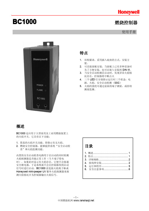
概述
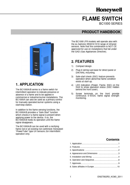
BC1000 是应用于大型商用及工业用燃烧装置上 的火焰开关。它具有以下功能:
1. 简易的火焰开关功能,即指示有无火焰。 2. 燃烧安全控制器,能够提供系统“安全启动检
查”和火焰监测功能。
内置的安全启动检查电路用于在启动的同时检测 火焰探测器是否能正常工作(当 1 端子得电 时)。如果此时显示有火焰存在,它便不会接通 安全继电器,于是系统就不会在控制器得到启动 信号时进行启动。BC1000 需连接火焰离子棒或 Honeywell mini-peeper UV 紫外火焰探测器来探 测火焰情况并为控制器输出火焰信号。
BC1000
BC1000 燃烧控制器
燃烧控制器
使用手册
特点
1. 结构紧凑,采用插入底座的方式,安装方 便。
2. 可直接面板安装,当面板上已有多种设备时 为了方便安装,也可以嵌入安装到 DIN 槽。
3. 当安全启动检测在启动时,发现异常火焰情 况存在,控制器将中断点火
4. 三个 LED 灯分别指示运行时三个状态:电 源,火焰,安全启动检测(SSC)
DIN 槽固定板
BC1000 燃烧控制器 DIN 槽
图 4 尺寸(DIN 槽安装)
C.底座的连线 1) 图 2 是一个典型的接线图示例。端子参照图 5。
①手动点火(持续引导火)
②火焰监测
主阀
点火 变压器
引导 火阀
火焰输出
点火 开关
启动
限位控制
自锁控制 (燃气/风压力开关)
安全启动 检查回路 火焰放大
③ 运行中如果火焰信号消失,则停止运行(燃气阀失电关闭)。
④ 引导火建立时间(PFEP): 应该满足标准要求。
-5-
2. 火焰检测系统(通常运行)
LED 显示 火焰建立
电源
火焰
SSC
(安全启动检 测)
待机 ● 电源 ○ ○
安全启动 ● 电源 ○ ● SSC
● 电源 ○ ● SSC
火焰监测
● 电源
● 电源
1. 易接触特殊化学品及腐蚀性气体(氨水,硫 磺,氯气,乙烯,酸性气体等)的地方。
2. 水中或过度潮湿的地方。 3. 温度过高及震动过于频繁的地方。 2) 为了避免瞬间电击导致设备的损坏,在安装前务 必断开主电源。在完成所有的接线及相应的检测 后,再将 BC1000 进行通电。 3) 不能超过端子的额定负荷功率。 4) 连接电源的电线同点火变压器的高压电线以及连 接火焰探测器的电线不能一起走线。紫外火焰探 测器的电线必须走单独导线管或屏蔽导线,和其 它电线分开,尤其是点火变压器的高压电源线必 须和 BC1000 分开至少 10cm 距离。
D.如何安装火焰探测器
判断火焰探测器安装位置是否正确,需要测量火焰电 压。通过将(+)和(-)端分别接到前面端子 9 和 10 上来测量火焰电压。推荐火焰电压大于 2Vdc。同 时,火焰探测电压不能高于 5.5V。
在火焰探测器安装好后,运行燃烧器,将火焰探测器 调节到最合适的位置。 如安装 Honeywell mini-peeper 紫外火焰探测器,请 参照 C7027/C7035/C7044 说明手册。
10. 紫外火焰探测器的 F 和 G 端导线必须和其它电线 分开,单独走导线管或屏蔽导线。特别注意不能 与点火变压器的高压电缆在一起走线。
11. 供电电压和频率必须符合 BC1000 不同型号的要 求。
12. 在接线和安装工作没有完成前务必断开所有电 源。错误的接线可能导致端子设备的损坏,甚至 出现触电现象。
点火开关
PFEP④ ● 电源 ● 火焰 ● SSC
点火开关
运行 ● 电源 ● 火焰 ● SSC
待机 ● 电源 ○ ○
引导火
持续点火③
主阀
主阀②③
限位 / 自锁
限位/ 自锁闭合
火焰信号
安全启动自 检①
火焰验证
① 如果在安全检查完成前,就检测到火焰,则停止运行,直到火焰信号消失再继续。
② 火焰输出信号被检测到,而且点火开关被释放。
4. BC1000 没有燃烧器点火必备的前吹扫功能。因 此,在设计时务必确认相应条列是否需要前吹扫 定时。
5. 所有的连线必须按照相关电气技术规范,条例 等。同时按照该产品说明进行正确的连线。当连 接燃料阀时,不能连接它到 L(相线)。这会引 起燃料阀非正常开启,导致燃料泄漏。是因为漏 电现象可能导致燃料阀通电启动。因此务必确认 燃料阀是连接到 N(中线)上的。
电源指示 LED 火焰指示 LED 安全启动检查 LED
1. 启动 2. 火焰输出 3. 公共端 4. SSC 输出(安全
启动检查)
5. F 6. G 7. L(相线) 8. N(中线) 9. + (火焰电压) 10. -(火焰电压)
底座
前面板拆下
图 2 底座端子和前面端子
图 3 尺寸
-3中国燃烧机网
AC220V—230V 50/60HZ
8W
火焰响 应时间 2±1秒
2±1秒
2±1秒
2±1秒
火焰 传感器 整流火焰 离子棒
C7035A C7027A 整流火焰 离子棒
C7035A C7027A
B.电气及环境要求
项目
规格
额定电压
AC110V50/60Hz,AC220V-230V,50/60Hz
电压波动范围
2. 禁止触摸 BC1000 的任何一个端子,这可能导致 您受到电击伤害。
3. BC1000 在启动时检测是否有火焰或者虚拟火焰 状态存在。BC1000 应用于周期性启停的燃烧器 中,如果该燃烧器不是周期性启停的,那为保证 正常的运行务必进行周期性检查(每 24 小时至少 一次)。对于一次连续工作大于 24 小时的燃烧系 统,我们推荐使用带有 Honeywell 自检功能的燃 烧系统。
额定电压的-15%到+10%
环境温度
单机安装:-20 到+60°C 两套以上设备组合安装:-20 到+45°C
环境湿度
低于 90%RH(不能使用在结露的环境下)
防震性能
x,y,z 各方向上耐震 0.5G 频率 10-150Hz
绝缘等级
当直流 500V 时端子对地的电阻高于 50MΩ
绝缘体强度
当交流 1800V 时 1 秒或交流 1500V 时 1 分钟端子对地 漏电量均低于 10mA(火焰探测器端子除外)
目录
1. 概述....................................................... 1 2. 特点....................................................... 1 3.详细规格............................................... 2 4. 接线和安装.......................................... 2 5. 运行和程序.......................................... 5 6. 安全注意事项.......................................6
行接地(如装在锅炉上,需接到锅炉炉体上)。 6) 点火变压器高压电缆务必连接紧固以防止连接故
障。同时点火变压器应直接安装在燃烧器上,或 安装在能与燃烧器相连的金属部件上。
DIN 槽安装板
前面板
电源指示 LED 火焰指示 LED 火焰电压 测量表端子
主体
接线与安装
A.注意 1) 该产品不能安装在以下地方:
设计寿命 端子负载 火焰强度 尺寸 重量
250,000 次正常运行(所有外界条件符合的情况下)
③-②:250VA ③-④:250VA
火焰开启:小于等于 1V 火焰关闭:大于等于 0.2V
42.5(宽)* 90.0(高) * 95.5(长)mm (包括底 座)
约 334 克(包括底座)
BC1000 燃烧控制器 5) 按照相应标准条例,燃烧器(火焰主体)必须进
6. 按实际设备,厂房的标准要求条例进行设置引导 火安全建立时间以及主火安全建立时间。如果点 火时间设置过长时,可能会出现残余燃料或爆炸 性气体在炉膛内混合引起爆炸。
-6-
7. 设备的火焰故障相应时间是 2 秒(误差±1 秒)。 必须严格按照工厂,设备,厂房相应标准 对 BC1000 进行安装和运行操作。(对欧洲标准来 说,应该满足 EN746-2)。
DIN 槽固定 图 1 外观
-2中国燃烧机网
底座
BC1000 燃烧控制器
B.控制器及底座的安装与拆卸 1) 如图 1 取下表面外壳,拧开固定的螺丝(大约逆时针拧 8 圈)。 2) 紧握控制器主体和底座,将主体部分用力从底座上拔出。此时,注意过分用力会导致设备损坏。 3) 用适合的螺丝固定将底座固定位置。 *如果底座安装在 DIN 槽上,请参考图 4.