电气工程及其自动化专业逆变器大学毕业论文英文文献翻译及原文
电气工程及其自动化专业_外文文献_英文文献_外文翻译_plc方面.
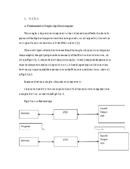
1、外文原文A: Fundamentals of Single-chip MicrocomputerTh e si ng le -c hi p m ic ro co mp ut er i s t he c ul mi na ti on of both t h e de ve lo pm en t of the dig it al com pu te r an d th e in te gr at ed c i rc ui t arg ua bl y t h e tow m os t s ig ni f ic an t i nv en ti on s o f t he 20th c e nt ur y [1].Th es e tow type s of arch it ec tu re are foun d in sin g le -ch i p m i cr oc om pu te r. Som e empl oy the spli t prog ra m/da ta me mo ry of the H a rv ar d ar ch it ect u re , sh ow n in Fig.3-5A -1, oth ers fo ll ow the p h il os op hy , wi del y ada pt ed for gen er al -p ur po se com pu te rs and m i cr op ro ce ss o r s, o f ma ki ng no log i ca l di st in ct ion be tw ee n p r og ra m and dat a me mo ry as in the Pr in ce to n arch ite c tu re , show n i n Fig.3-5A-2.In gen er al ter ms a sin gl e -chi p mic ro co mp ut er i sc h ar ac te ri zed b y t he i nc or po ra ti on of a ll t he un it s of a co mp uter i n to a sin gl e d ev i ce , as sho wn inFi g3-5A -3.Fig.3-5A-1 A Harvard typeFig.3-5A-2. A conventional Princeton computerFig3-5A-3. Principal features of a microcomputerRead only memory (ROM.R OM is usua ll y for the pe rm an ent,n o n-vo la ti le stor a ge of an app lic a ti on s pr og ra m .M an ym i cr oc om pu te rs and m are inte nd e d for high -v ol um e ap pl ic at ions a n d he nc e t h e eco n om ic al man uf act u re of th e de vic e s re qu ir es t h at t he cont en t s o f t he prog ra m me m or y be co mm it t ed perm a ne ntly d u ri ng the man ufa c tu re of ch ip s .Cl ea rl y, thi s im pl ie s a r i go ro us app ro ach to ROM cod e deve l op me nt sin ce cha ng es can not b e mad e afte r manu f a c tu re .Th is dev e lo pm en t proc ess may invo lv e e m ul at io n us in g aso ph is ti ca te d de ve lo pm en t sy ste m wit h a h a rd wa re emu la tio n cap ab il it y as w el l as the use o f po we rf ul s o ft wa re too ls.So me man uf act u re rs pro vi de add it io na l RO M opt i on s by i n cl ud in g in their ra n ge dev ic es wit h (or int en de d fo r use wit h u s er pro gr am ma ble me mo ry. Th e sim p le st of th es e is usu al ly d e vi ce whi ch can op er at e in a micro p ro ce ssor mod e by usi ng som e o f the inp ut /outp u t li ne s as an ad dr es s an d da ta b us fora c ce ss in g ex te rna l mem or y. Thi s t y pe of de vi ce can beh av ef u nc ti on al ly as th e sing le chip mi cr oc om pu te r from whi ch it is d e ri ve d al be it wit h re st ri ct ed I/O and a mod if ied ex te rn al c i rc ui t. The use of thes e d ev ic es is com mo n eve n in prod uc ti on c i rc ui ts wher e t he vo lu me does no tj us ti f y t h e d ev el o pm en t c osts o f c us to m o n -ch i p R OM [2];t he re c a n s ti ll bea s ignif i ca nt saving i n I /O and o th er c h ip s com pa re d to a conv en ti on al mi c ro pr oc es sor b a se d ci rc ui t. Mor e ex ac t re pl ace m en t fo r RO M dev i ce s ca n be o b ta in ed in th e fo rm of va ri an ts w it h 'p ig gy -b ack 'E P RO M(Er as ab le pro gr am ma bl e ROM s oc ke ts or dev ic e s with EPROM i n st ea d o f RO M 。
电气工程及其自动化专业_外文文献_英文文献_外文翻译_plc方面
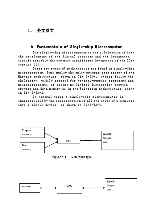
1、外文原文A: Fundamentals of Single-chip MicrocomputerTh e si ng le-c hi p m ic ro co mp ut er i s t he c ul mi na ti on of b oth t h e de ve lo pm en t o f t he d ig it al co m pu te r an d th e i n te gr at edc i rc ui t a rg ua bl y t h e to w m os t s ig ni f ic an t i nv en ti on s o f t he20th c e nt ur y [1].Th es e t ow ty pe s of ar ch it ec tu re a re fo un d i n s in g le-c hip m i cr oc om pu te r. So m e em pl oy t he spl i t pr og ra m/da ta m e mo ry o f th e H a rv ar d ar ch it ect u re, sh ow n in Fi g.3-5A-1, o th ers fo ll ow t he p h il os op hy, wi del y a da pt ed f or ge n er al-p ur po se co m pu te rs a nd m i cr op ro ce ss o r s, o f ma ki ng n o log i ca l di st in ct ion be tw ee np r og ra m an d d at a m e mo ry a s i n t he P r in ce to n ar ch ite c tu re, sh ow n i n F ig.3-5A-2.In g en er al te r ms a s in gl e-chi p m ic ro co mp ut er i sc h ar ac te ri zed b y t he i nc or po ra ti on of a ll t he un it s of a co mp ut er i n to a s in gl e d ev i ce, as s ho wn in Fi g3-5A-3.Fig.3-5A-1 A Harvard typeFig.3-5A-2. A conventional Princeton computerFig3-5A-3. Principal features of a microcomputerRead only memory (ROM).R OM i s us ua ll y f or th e p e rm an en t,n o n-vo la ti le s tor a ge o f an a pp lic a ti on s pr og ra m .M an ym i cr oc om pu te rs an d m ar e in te nd e d f or hi gh-v ol um e a p pl ic at io ns a n d he nc e t h e eco n om ic al m an uf act u re o f th e de vic e s re qu ir es t h at t he co nt en t s o f t he pr og ra m me m or y b e co mm it t ed pe rm a ne nt ly d u ri ng t he m an ufa c tu re o f ch ip s .Cl ea rl y, t hi s i m pl ie s ar i go ro us a pp ro ach to R OM c od e de ve l op me nt s in ce ch a ng es c an no t b e m ad e af te r m anu f a c tu re .Th is d ev e lo pm en t pr oc ess ma y in vo lv e e m ul at io n us in g a so ph is ti ca te d d e ve lo pm en t sy ste m w it h ah a rd wa re e mu la tio n c ap ab il it y as w el l as t he u se o f po we rf ul s o ft wa re t oo ls.So me m an uf act u re rs p ro vi de ad d it io na l RO M opt i on s byi n cl ud in g i n th eir r a n ge d ev ic es wi t h (or i nt en de d f o r u se w it h) u s er p ro gr am ma ble me mo ry. Th e sim p le st o f th es e i s u su al lyd e vi ce w hi ch c an o p er at e in a mi cro p ro ce ss or m od e b y u si ng s om e o f t he i np ut/o utp u t li ne s as a n a d dr es s an d da ta b us f ora c ce ss in g ex te rna l m em or y. T hi s t y pe o f de vi ce ca nb eh av ef u nc ti on al ly a s t h e si ng le ch ip mi cr oc om pu te r fro m w hi ch it is d e ri ve d al be it wi t h re st ri ct ed I/O a nd a m od if ied ex te rn alc i rc ui t. Th e u se o f th es ed ev ic es i s c om mo ne ve n i n pr od uc ti on c i rc ui ts wh er e t he vo lu me do es no t j us tif y t h e d ev el o pm en t c os ts o f c us to m o n-ch i p R OM[2];t he re c a n s ti ll be a s ig nif i ca nt sa vi ng i n I/O an d o th er c h ip s c om pa re d t o a co nv en ti on al mi c ro pr oc es so r b a se d ci rc ui t. Mo r e ex ac t re pl ace m en t fo r RO M dev i ce s ca n be o b ta in ed i n th e f o rm o f va ri an ts w it h 'p ig gy-b ack'E P RO M(Er as ab le pr o gr am ma bl e RO M )s oc ke ts o r d ev ic e s wi th EP RO M i n st ea d o f RO M 。
(完整版)电气与信息学院自动化专业毕业设计(论文)外文翻译-电子

电气与信息学院自动化专业毕业设计(论文)外文翻译Electonic power steering system Research andDesign电子动力转向系统的研究与设计注:本毕业设计(论文)外文翻译文档前半部分为英文部分,后半部分为中文部分。
本外文翻译由专业人员翻译,内容详细数据全面,得到导师的一致好评。
值得大家借鉴参考。
本文档下载后为WORD版本,可按需直接编辑。
Electronic power steering systemWhat it isElectrically powered steering uses an electric motor to drive either the power steering is therefore independent of engine speed, resulting in significant energy savings.How it works :Conventional power steering systems use an engine accessory belt to drive the pump, providing pressurized fluid that operates a piston in the power steering gear or actuator to assist the driver.In electro- by an electric motor. Pump speed is regulated by an electric controller to vary pump pressure and flow, providing steering efforts tailored for different driving situations. The pump can be run at low speed or shut off to provide energy savings during straight ahead driving (which is most of the time in most world markets).Direct electric steering uses an electric motor attached to the steering rack via a gear mechanism (no pump or fluid). A variety of motor types and gear drives is possible. A microprocessor controls steering dynamics and driver effort. Inputs include vehicle speed and steering, wheel torque, angular position and turning rate.Working In Detail:A "steering sensor" is located on the input shaft where it enters the gearbox one: a "torque sensor" that converts steering torque input and its direction into voltage signals, and a "rotation sensor" that converts the rotation speed and direction into voltage signals. An "interface" circuit that shares the same sensor into signals the control electronics can process.Inputs from the steering sensor are digested by a microprocessor control unit that also monitors input from the vehicle's speed sensor. The sensor inputs are then compared to determine the control unit's memory. The control unit then sends out the appropriate command to the "power unit" which then supplies the electric motor with current. The motor pushes the rack to the right or left depending on which way the voltage flows (reversing the current reverses the direction the motor spins). Increasing the current to the motor increases the amount of power assist.The system which left or right power assist is provided in response to input from the steering torque and rotation sensor's inputs; a "return" control mode which is used to assist steering return after completing a turn; and a "damper" control mode that changes with vehicle speed to improve road feel and dampen kickback.If the steering wheel is turned and the full-lock position and steering assist reaches a maximum, the control unit reduces current to the electric motor to prevent an overload situation that might damage the motor. Thecontrol unit is also designed to protect the motor against voltage surges from a faulty alternator or charging problem.The electronic steering control unit is capable of self-diagnosing faults by monitoring the system's inputs and outputs, and the driving current of the electric motor. If a problem occurs, the control unit turns the system off by actuating a fail-safe relay in the power unit. This eliminates all power assist, causing the system to revert back to manual steering. A dash EPS warning light is also illuminated to alert the driver. To diagnose the problem, a technician jumps the terminals on the service check connector and reads out the trouble codes.click , fuel savings and package flexibility, at no cost penalty.Europe's a short time, electric steering will make it to the U.S., too. "It's just just a matter of time," says Aly Badawy, director of research and development for Delphi Saginaw Steering Systems in Saginaw, Mich. "The issue was cost and that's behind us now. By 2002 the U.S. the cost of electric power steering will absolutely be a wash over for electric steering. But by 2010, a TRW Inc. internal study estimates that one out of every three cars produced in the world will be equipped with some form ofelectrically-assisted steering. The Cleveland-based supplier claims its new steering systems could improve fuel economy by up to 2 mpg, while enhancing be run off a laptop computer. "They can take that computer and plug it in, attach it to the controller and change all the the fly," Badawy says. "It used to take months." Delphi in '99.Electric steering units are normally placed in one of three positions: column-drive, pinion-drive and rack-drive. Which system will become the norm is still unclear. Short term, OEMs will choose the steering system that is easiest to integrate into an existing platform. Obviously, greater potential comes from designing the system into an all-new platform. "We ," says Dr. Herman Strecker, group vice president of steering systems division at ZF in Schwaebisch Gmuend, Germany. "It's up to the market and OEMs which version finally will be used and manufactured." "The large manufacturers Sterling Heights, Mich. His company offers a portfolio of electric steering systems (-, and column-drive). TRW originally concentrated on what it still believes is the purest engineering solution for electric steering--the rack-drive system. The system is sometimes refer to as direct drive or ballnut drive. Still, this winter TRW in exchange for its electric column-drive steering technology and as sets. Initial production of the column and pinion drive electric steering systems is expected to begin in Birmingham, England, in 2000."What we lack is the credibility in the steering market," says Brendan Conner, managing director, TRWLucasVarity Electric Steering Ltd. "The combination with TRW provides us with a good opportunity for us to bridge that gap." LucasVarity currently 11 different vehicle types,mostly European. TRW is currently supplying its EAS systems for Ford and Chrysler EVs in North America and for GM's new Opel Astra.In 1995, according to Delphi, traditional 7596 of all vehicles sold globally. That 37-million vehicle pool consumes about 10 million gallons in relates to an electrically powered drive mechamsm for providing powered assistance to a vehicle steering mechanism. According to one aspect of the present invention, there is provided an electrically powered driven mechanism for providing powered assistance to a vehicle steering mechanism electrically powered drive motor drivingly connected to the rotatable member and a controller which is arranged to control the speed and direction of rotation of the drive motor in response to signals received from the torque sensor, the torque sensor including a sensor shaft adapted for connection to the rotatable member to form an extension thereof so that torque is transmitted through said sensor shaft when the rotatable member is manually rotated and a strain gauge mounted on the sensor shaft for producing a signal indicative of the amount of torque being transmitted through said shaft. Preferably the sensor shaft is non-rotatably mounted at one axial end in a first coupling member and is non-rotatably mounted at its opposite axial end in a second coupling member, the first and second coupling members being inter-engaged to permit limited rotation there between so that torque under a predetermined limit is transmitted by the sensor shaft only and so that torque above said predetermined limit is transmitted through the first and second coupling members. The first and second coupling members are preferably arranged to act as a bridge for drivingly connecting first and second portions of the rotating member toone another. Preferably the sensor shaft is of generally rectangular cross-section throughout the majority of its length. Preferably the strain gauge includes one or more SAW resonators secured to the sensor shaft. Preferably the motor is drivingly connected to the rotatable member via a clutch .Preferably the motor includes a gear box and is concentrically arranged relative to the rotatable member. Various aspects of the present invention will which :Figure 1 is a diagrammatic view of a vehicle steering mechanism including an electrically powered drive mechanism according to the present invention, Figure 2 is a flow diagram illustrating interaction between various components of the drive mechanism shown in Figure 1 ,Figure 3 is an axial section through the drive mechanism shown in Figure 1, Figure 4 is a sectional view taken along lines IV-IV in Figure 3,Figure 5 is a more detailed exploded view of the input drives coupling shown in Figure 3, and Figure 6 is a more detailed exploded view of the clutch showing in Figure 3. Referring initially to Figure 1 , there is shown a vehicle steering mechanism 10 drivingly connected to a pair of steerable road wheels The steering mechanism 10 shown includes a rack and pinion assembly 14 connected to the road wheels 12 via joints 15. The pinion(not shown) of assembly 14 is rotatably driven by a manually rotatable member in the form of a steering column 18 which is manually rotated by a steering wheel 19.The steering column 18 includes an electric powered drive mechanism 30 which includes an electric drive motor (not shown in Figure 1) for driving the pinion in response to torque loadings in the steering column 18 in order to provide power assistance for the operative when rotating the steering wheel 19.As schematically illustratedin Figure 2, the electric powered drive mechanism includes a torque sensor20 which measures the torque applied by the steering column 18 when driving the pinion and supplies a signal to a controller 40. The controller 40 is connected to a drive motor 50 and controls the electric current supplied to the motor 50 to control the amount of torque generated by the motor 50 and the direction of its rotation. The motor 50 is drivingly connected to the steering column 18 preferably via a gear box 60, preferably an epicyclic gear box, and a clutch 70. The clutch 70 is preferably permanently engaged during normal operation and is operative under certain conditions to isolate drive from the motor 50 to enable the pinion to be driven manually through the drive mechanism 30. This is a safety feature to enable the mechanism to function in the event of the motor 50 attempting to drive the steering column too fast andor in the wrong direction or in the case where themotor andor gear box assembly including a short sensor shaft on which is mounted a strain gauge capable of accurately measuring strain in the sensor shaft brought about by the application of torque within a predetermined range. Preferably the predetermined range of torque which is measured is 0-lONm; more preferably is about l-5Nm.Preferably the range of measured torque corresponds to about 0-1000 microstrain and the construction of the sensor shaft is chosen such that a torque of 5Nm will result in a twist of less than 2°in the shaft, more preferably less than 1 °.Preferably the strain gauge is a SAW resonator, a suitable SAW resonator being of axis and at 90° to one another. Preferably the resonators operate with a resonance controller 40 of 1 MHz ±500 KHz dependingupon the direction of rotation of the sensor shaft. Thus, when the sensor shaft is not being twisted due to the absence of torque, it produces a 1 MHz signal. When the sensor shaft is twisted in one direction it produces a signal between 1.0 to 1.5 MHz. When the sensor shaft is twisted in the opposite direction it produces a signal between 1.0 to 0.5 MHz. Thus the same sensor is able to produce a signal indicative of the degree of torque and also the direction of rotation of the sensor shaft. Preferably the amount of torque generated by the motor in response to a measured torque of between 0-10Nm is 0-40Nm and for a measured torque of between l-5Nm is 0-25Nm.Preferably a feed back circuit is provided whereby the electric current being used by the motor is measured and compared by the controller 40 to ensure that the motor is running in the correct direction and providing the desired amount of power assistance. Preferably the controller acts to reduce the measured torque to zero and so controls the motor to increase its torque output to reduce the measured torque. A vehicle speed sensor (not shown) is preferably provided which sends a signal indicative of vehicle speed to the controller. The controller uses this signal to modify the degree of power assistance provided in response to the measured torque. Thus at low vehicle speeds maximum power assistance will be provided and a software and so is able to function more reliably in a car vehicle environment. It is envisaged that a logic sequence not be as . Automobile traffic in the actual process, at the time to about 5 percent of the time travelling, the HPS system, engine running, the pumps will always be in working condition, the oil pipeline in circulation, so that vehicle fuelconsumption rate by 4 % To 6%, while EPS only when needed for energy, vehicle fuel consumption rates only increased by 0.5 percent.3) "Road sense of" good. Because EPS internal use of rigid, system of the lag can be controlled by software, and can be used in accordance with the operation of the driver to adjust.4) back to being good. EPS simple structure of small internal resistance, is a good back, get back to being the best characteristics, improve vehicle . HPS the not be recovered, the environmental pollution are to a certain extent, while EPS almost no pollution to the environment.6) can be independent of the engines work. EPS for battery powered devices, as long as sufficient battery power, no matter what the condition for the engine, can produce power role.7) should using electric power steering gear, the car of the economy, power and mobility the car is a new power steering system device, developed rapidly in recent years both at the same time there are also potential safety problems. In the analysis This unique product on the basis of the author of the characteristics of electronic control devices, security clearance just that the factors that deal with security measures, and discussed a number of concerns the safety of specific issues. The results show that : Existing standards can not meet the electric power steering device security needs and made the electric power steering device safety evaluation of the idea. Research work on the electric power steering device development and evaluation of reference value.电子动力转向系统图1电子动力转向系统的工作原理:电子动力转向系统是通过一个电动机来驱动动力方向盘液压泵或直接驱动转向联动装置。
电气工程及其自动化专业英语作文范文

电气工程及其自动化专业英语作文范文Electrical Engineering and Automation: An Integral Part of Modern SocietyIntroductionElectrical Engineering and Automation, a discipline that has evolved significantly over the past few decades, has become an integral part of modern society. Its widespread applications in industry, agriculture, national defense, and various other fields have propelled it to a pivotal position in the global economy.Historical PerspectiveThe field of Electrical Engineering and Automation was first established approximately forty years ago. As a relatively new discipline, it has quickly grown to encompass a wide range of subfields and applications. From the design of switches for aerospace aircraft to the development of complex automated systems, its influence is pervasive.Core ComponentsThe core of Electrical Engineering and Automation lies in its ability to integrate electricity, machines, and intelligent systems to automate various tasks. This integration enables efficiency, precision, and safety in a wide range of applications.•Electricity and Machines: Electricity provides the power that drives machines and systems. Understanding the behavior ofelectrical circuits, voltage sources, current sources, andvarious network elements is crucial for the effective designand operation of automated systems.•Automation: Automation refers to the use of technology to control and monitor processes and machines with minimal humanintervention. It relies on sensors, actuators, and intelligentcontrollers to achieve desired outcomes.Challenges and OpportunitiesWhile Electrical Engineering and Automation offers immense opportunities for growth and development, it also poses significantchallenges. The complexity of modern systems requires a high level of technical knowledge and expertise. Additionally, the rapid pace of technological advancement requires constant updating of skills and knowledge.However, these challenges also present opportunities for innovation and growth. As new technologies emerge, there is a need for engineers and technicians who can understand and apply them effectively. This creates opportunities for those with a passion for learning and a willingness to adapt to new challenges.ConclusionIn conclusion, Electrical Engineering and Automation is a dynamic and exciting field that offers immense opportunities for growth and development. Its applications are pervasive, and its influence on society is profound. As we continue to push the boundaries of technology, Electrical Engineering and Automation will play an increasingly important role in shaping our future.。
(自动化专业)毕业论文文献翻译中英文对照
(自动化专业)毕业论文文献翻译中英文对照毕业设计外文资料翻译题目可编程控制器技术讨论与未来发展专业电气工程及其自动化PLC technique discussion and future developmentK. Begain, M. ErmelChair for Telecommunications, Dresden University of Technology,01062 Dresden, GermanyAbstract: Programmable Logic Controllers (PLC), a computing device invented by Richard E.Morley in 1968, have been widely used in industry including manufacturing systems, transportation systems, chemical process facilities, and many others. At that time, the PLC placed the hardwired logic with soft-wired logic or so-called relay ladder logic(RLL), a programming language visually resembling the hardwired logic, and reduced thereby the configuration time from 6 months down to 6 days [Moody and Morley,1999].Although PC based control has started to come into place, PLC based control will remain the technique to which the majority of industrial applications will adhere due to its higher performance, lower price, and superior reliability in harsh environments. Moreover, according to a study on the PLC market of Frost and Sullivan [1995], an increase of the annual sales volume to 15 million PLCs per year with the hardware value of more than 8 billion US dollars has been predicted, though the prices of computing hardware is steadily dropping. The inventor of the PLC, Richard E Morley, fairly considers the PLC market as a 5-billion industry at the present time.Key Words:PLC ,performance ,market1 IntroductionAlong with the development of the ages, the technique that is nowadays is also gradually perfect, the competition plays more more strong; the operation that list depends the artificial has already can't satisfied with the current manufacturing industry foreground, also can't guarantee the request of the higher quantity and high new the image of the technique business enterprise.The people see in produce practice, automate brought the tremendous convenience and the product quantities for people up of assurance, also eased the personnel's labor strength, reduce the establishment on the personnel. The target control of the hard realization in many complicated production lines, whole and excellent turn, the best decision etc., well-trained operation work, technical personnel or expert, governor but can judge and operate easily, can acquire the satisfied result. The research target of the artificial intelligence makes use of the calculator exactly to carry out, imitate these intelligences behavior, moderating the work through person's brain and calculators, with the mode that person's machine combine, for resolve the very complicated problem to look for the best pathWe come in sight of the control that links after the electric appliances in various situation, that is already the that time generation past, now of after use in the mold a perhaps simple equipments of grass-roots control that the electric appliances can do for the low level only;And the PLC emergence also became the epoch-making topic, adding the vivid software control through a very and stable hardware, making the automation head for the new high tide.2 PLC characteristics and containment2.1 The PLC biggest characteristicsThe PLC biggest characteristics lie in: The electrical engineering teacher already no longer electric hardware up too many calculationses of cost, as long as order the importation that the button switch or the importation of the sensors order to link the PLC up can solve problem, pass to output to order the conjunction contact machine or control the start equipments of the big power after the electric appliances, but the exportation equipments direct conjunction of the small power can.Figure 1. Open frame PLC2.2 PLC internal containmentPLC internal containment have CPU, and take to have an I/ O for expand of exterior to connect a people's address and saving machine three big pieces to constitute, CPU core is from an or many is tired to add the machine to constitute, mathematics that they have the logic operation ability, and can read the procedure save the contents of the machine to drive the homologous saving machine and I/ Os to connect after pass the calculation; The I/ O add inner part is tired the input and output system of the machine and exterior link, and deposit the related data into the procedure saving machine or data saving machine; The saving machine can deposit the data that the I/ O input in the saving machine, and in work adjusting to become tired to add the machine and I/ Os to connect, saving machine separately saving machine RAM of the procedure saving machine ROM and datas, the ROM can can do deposit of the data permanence in the saving machine, but RAM only for the CPU computes the temporary calculation usage of hour of buffer space.Figure 2. PLC input and output circuits2.3 PLC advantageThe PLC anti- interference is very and excellent, our root need not concern its service life and the work situation bad, these all problems have already no longer become the topic that we fail, but stay to our is a concern to come to internal resources of make use of the PLC to strengthen the control ability of the equipments for us, make our equipments more gentle.PLC language is not we imagine of edit collected materials the language or language of Cs to carry on weaving the distance, but the trapezoid diagram that the adoption is original after the electric appliances to control, make the electrical engineering teacher while weaving to write the procedure very easy comprehended the PLC language, and a lot of non- electricity professional also very quickly know and go deep into to the PLC.3 HMIIs PLC one of the advantage above and only, this is also one part that the people comprehend more and easily, in a lot of equipmentses, the people have already no longer hoped to see too many control buttons, they damage not only and easily and produce the artificial error easiest, small is not a main error perhaps you can still accept; But lead even is a fatal error greatly is what we can't is tolerant of. New technique always for bringing more safe and convenient operation for us, make we a lot of problems for face on sweep but light, do you understand the HMI? Says the HMI here you basically not clear what it is, also have no interest understanding, change one inside text explains it into the touch to hold or man-machine interface you knew, it combines with the PLC to our larger space.HMI the control not only only is reduced the control press button, increase the vivid of the control, more main of it is can sequence of, and at can the change data input to output the feedback with data, control in the temperature curve of imitate but also can keep the manifestation of view to come out. And can write the function help procedure through a plait to provide the help of various what lies in one's power, the one who make operate reduces the otiose error. Currently the HMI factory is also more and more, the function is also more and more strong, the price is also more and more low, the noodles of the usage are wide more and more. The HMI foreground can say that think ° to be good very.4 PLC correspondence and data transmissionAt a lot of situations, the list is is a smooth movement that can't guarantee theequipments by the control of the single machine, but pass the information exchanges of the equipments and equipments to attain the result that we want. For example fore pack and the examination of the empress work preface, we will arrive wrapping information feedback to examine the place, and examine the information of the place to also want the feedback to packing. Pass the information share thus to make both the chain connect, becoming a total body, the match of your that thus make is more close, at each other attain to reflect the result that mutually flick.The PLC correspondence has already come more more body now its value, at the PLC and correspondence between PLCs, can pass the communication of the information and the share of the datas to guarantee that of the equipments moderates mutually, the result that arrive already to repair with each other. Data conversion the adoption RS232 between PLC connect to come to the transmission data, but the RS232 pick up a people and can guarantee 10 meters only of deliver the distance, if in the distance of 1000 meters we can pass the RS485 to carry on the correspondence, the longer distance can pass the MODEL only to carry on deliver.The PLC data transmission is just to be called a form to it in a piece of and continuous address that the data of the inner part delivers the other party, we, the PLC of the other party passes to read data in the watch to carry on the operation. If the data that data in the watch is a to establish generally, that is just the general data transmission, for example today of oil price rise, I want to deliver the price of the oil price to lose the oil ally on board, that is the share of the data; But take data in the watch for an instruction procedure that controls the PLC, that had the difficulty very much, for example you have to control one pedestal robot to press the action work that you imagine, you will draw up for it the form that a procedure combine with the data sends out to pass by.Figure 3. PLC connection with experiments board.4.1 Form of information transmission4.1.1 Simplex and DuplexThe form that information transport contain Simplex, the Half duplex and the Full duplex.The meaning of the Simplex also is to say both, a can send out only, but a can receive only, for example a spy he can receive the designation of the superior only, but can't give the superior reply; Half duplex is also 2 and can can send out similar to accept the data, but can't send out and accept at the same time, for example when you make a phone call is to can't answer the phone, the other party also; But the Half duplex is both can send out and accept the data, and can send out and accept at the same time. Be like the Internet is a typical example.4.1.2 Synchronous and AsynchronousThe process that information transport also has synchronous and asynchronous: The data line and the clock lines are synchronous when synchronous meaning lie in sending out the data, is also the data signal and the clock signals to be carry on by the CPU to send out at the same time, this needs to all want the specialized clock signal each other to carry on the transmission and connect to send, and is constrained, the characteristics of this kind of method lies in its speed very quick, but correspond work time of take up the CPU and also want to be long oppositely, at the same time the technique difficulty also very big. Itsrequest lies in can'ting have an error margins in a datas deliver, otherwise the whole pieceaccording to compare the occurrence mistake, this on the hardware is a bigger difficulty. Applied more and more extensive in some appropriative equipmentses, be like the appropriative medical treatment equipments, the numerical signal equipments...etc., in compare the one data deliver, its result is very good.And asynchronous is an application the most extensive, this receive benefit in it of technique difficulty is opposite and want to be small, at the same time not need to prepare the specialized clock signal, its characteristics to lie in, its data is partition, the long-lost send out and accept, be the CPU is too busy of time can grind to a stop sex to work, also reduced the difficulty on the hardware, the data throw to lose at the same time opposite want to be little, we can pass the examination of the data to observe whether the data that we send out has the mistake or not, be like strange accidentally the method, tired addition and eight efficacies method etc., can use to helps whether the data that we examine to send out have or not the mistake occurrence, pass the feedback to carry on the discriminator.4.1.3 Parallel and SerialA line of transmission of the information contain a string of and combine the cent of: The usual PLC is 8 machines, certainly also having 16 machines. We can be an at the time of sending out the data a send out to the other party, also can be 88 send out the data to the other party, an and 8 differentiationses are also the as that we say to send out the data and combine sends out the data. A speed is more and slowly, but as long as 2 or three lines can solve problem, and can use the telephone line to carry on the long range control. But combine the oscular transmission speed is very quick of, it is a string of oscular of 25600%, occupy the advantage in the short distance, the in view of the fact TTL electricity is even, being limited by the scope of one meter generally, it combine unwell used for the data transmission of the long pull, thus the cost is too expensive.Under a lot of circumstances we are total to like to adopt the string to combine the conversion chip to carry on deliver, under this kind of circumstance not need us to carry on to depositted the machine to establish too and complicatedly, but carry on the data exchanges through the data transmission instruction directly, but is not a very viable way in the correspondence, because the PLC of the other party must has been wait for your data exportation at the time of sending out the data, it can't do other works.4.2 InterruptWhen you are reading the book, you hear someone knock on door, you stop to start up of affair, open the door and combine to continue with the one who knock on door a dialogue, the telephone of this time rang, you signal hint to connect a telephone, afterconnecting the telephone through, return overdo come together knock on door to have a conversation, after dialogue complete, you continue again to see your book, this kind of circumstance we are called the interruption to it, it has the authority, also having sex of have the initiative, the PLC had such function .Its characteristics lie in us and may meet the urgently abrupt affairs in the operation process of the equipments, we want to stop to start immediately up of work, the whereabouts manages the more important affair, this kind of circumstance is we usually meet of, PLC while carry out urgent mission, total will keep the current appearance first, for example the address of the procedure, CPU of tired add the machine data etc., be like to to stick down which the book that we see is when we open the door the page or simply make a mark, because we treat and would still need to continue immediately after book of see the behind. The CPU always does the affair that should do according to our will, but your mistake of give it an affair, it also would be same to do, this we must notice.The interruption is not only a, sometimes existing jointly with the hour several inside break, break off to have the preferred Class, they will carry out the interruption of the higher Class according to person's request. This kind of breaks off the medium interruption to also became to break off the set. The Class that certainly break off is relevant according to various resources of CPU with internal PLC, also following a heap of capacity size of also relevant fasten.The contents that break off has a lot of kinds, for example the exterior break off, correspondence in of send out and accept the interruption and settle and the clock that count break off, still have the WDT to reset the interruption etc., they enriched the CPU to respond to the category while handle various business. Speak thus perhaps you can't comprehend the internal structure and operation orders of the interruption completely also, we do a very small example to explain.4.3 Emergency stop buttonEach equipments always will not forget a button, it also is at we meet the urgent circumstance use of, that is nasty to stop the button. When we meet the Human body trouble and surprised circumstances we as long as press it, the machine stops all operations immediately, and wait for processing the over surprised empress recover the operation again.Nasty stop the internal I/ O of the internal CPU of the button conjunction PLC to connect up, be to press button an exterior to trigger signal for CPU, the CPU carries on to the I/ O to examine again, being to confirm to have the exterior to trigger the signal, CPU protection the spot breaks off procedure counts the machine turn the homologous exteriorI/ O automatically in the procedure to go to also, be exterior interruption procedure processing complete, the procedure counts the machine to return the main procedure to continue to work.Have 1:00 can what to explain is we generally would nasty stop the button of exterior break off to rise to the tallest Class, thus guarantee the safety.4.4 PLC Counting functionWhen we are work a work piece, giving the PLC a signal, counting PLC inner part the machine add 1 to compute us for a day of workload, a count the machine and can solve problem in brief, certainly they also can keep the data under the condition of dropping the electricity, urging the data not to throw to lose, this is also what we hope earnestly.The PLC still has the function that the high class counts the machine, being us while accept some datas of high speed, the high speed that here say is the data of the in all aspects tiny second class, for example the bar code scanner is scanning the data continuously, calculating high-speed signal of the data processor DSP etc., we will adopt the high class to count the machine to help we carry on count. It at the PLC carries out the procedure once discover that the high class counts the machine to should of interruption, will let go of the work on the hand immediately. The trapezoid diagram procedure that passes by to weave the distance again explains the high class for us to carry out procedure to count machine would automatic performance to should of work, thus rise the Class that the high class counts the machine to high one Class.You heard too many this phrases perhaps:" crash", the meaning that is mostly is a workload of CPU to lead greatly, the internal resources shortage etc. the circumstance can't result in procedure circulate. The PLC also has the similar circumstance, there is a watchdog WDT in the inner part of PLC, we can establish time that a procedure of WDT circulate, being to appear the procedure to jump to turn the mistake in the procedure movement process or the procedure is busy, movement time of the procedure exceeds WDT constitution time, the CPU turn but the WDT reset the appearance. The procedure restarts the movement, but will not carry on the breakage to the interruption.Figure 4. Overall board design.5 PLC development in the futureThe PLC development has already entered for network ages of correspondence from the mode of the one, and together other works control the net plank and I/ O card planks to carry on the share easily. A state software can pass all se hardwares link, more animation picture of keep the view to carries on the control, and cans pass the Internet to carry on the control in the foreign land, the blast-off that is like the absolute being boat No.5 is to adopt this kind of way to make airship go up the sky.The development of the higher layer needs our continuous effort to obtain.The PLC emergence has already affected a few persons fully, we also obtained more knowledge and precepts from the top one experience of the generation, coming to the continuous development PLC technique, push it toward higher wave tide.References[1] R. Alur, C. Courcoubetis, and D. Dill. Model-Checking for Real-Time Systems.In Fifth Annual IEEE Symp. on Logic in Computer Science, pages 414{425.IEEE Press, 1990. [2] R. Alur and D.L. Dill. A theory of timed automata. Theoret. Comput. Sci.,126:183{235, 1994.[3] R. Alur, T. Henzinger, and E. Sontag, editors. Hybrid Systems III, volume 1066 of Lecture Notes in Computer Science. Springer-Verlag, 1996.[4] J. Bengtsson, K.G. Larsen, F. Larsson, P. Pettersson, and Wang Yi. Uppaal {a ToolSuite for Automatic Verification of Real-Time Systems. In Alur et al.[3]. 232{243.[5] D. Bosscher, I. Polak, and F. Vaandrager. Verification of an Audio Control Protocol. InH. Langmaack, W.-P. de Roever, and J. Vytopil, editors, Formal Techniques in Real-Time and Fault-Tolerant Systems, volume 863 of Lecture Notes in Computer Science, pages 170{192. Springer-Verlag, 1994.PLC technique discussion and future development, 2010, 130(9): 2436-2443.可编程控制器技术讨论与未来发展K.培根, M. 厄米尔通信教授, 德累斯顿科技大学,01062德累斯顿,德国摘要可编程逻辑控制器(PLC)是Richard E.Morley在1968年发明的一种具备运算功能的设备,现已被广泛的应用到工业中,包括制造系统、交通系统、化工过程设备等。
电气工程及其自动化专业 外文文献 英文文献 外文翻译 plc方面

1、外文原文(复印件)A: Fundamentals of Single-chip MicrocomputerTh e si ng le-ch i p mi cr oc om pu ter is t he c ul mi nat i on o f bo th t h e d ev el op me nt o f th e d ig it al com p ut er an d t he int e gr at ed ci rc ui ta r gu ab ly th e t ow m os t s i gn if ic ant i nv en ti on s o f t h e 20t h c en tu ry[1].Th es e to w typ e s of a rc hi te ctu r e ar e fo un d i n s in gl e-ch ip m i cr oc om pu te r. So m e em pl oy t he sp l it p ro gr am/d ata me mo ry o f th e H a rv ar d ar ch it ect u re, sh ow n i n -5A, ot he rs fo ll ow th e ph i lo so ph y, w i de ly a da pt ed fo r g en er al-p ur pos e c om pu te rs an d m i cr op ro ce ss or s, o f m a ki ng no lo gi c al di st in ct io n b e tw ee n p ro gr am a n d da t a m em ory a s i n th e Pr in cet o n ar ch it ec tu re,sh ow n in-5A.In g en er al te r ms a s in gl e-chi p m ic ro co mp ut er i sc h ar ac te ri zed b y the i nc or po ra tio n of al l t he uni t s o f a co mp ut er i n to a s in gl e dev i ce, as s ho wn in Fi g3-5A-3.-5A-1 A Harvard type-5A. A conventional Princeton computerFig3-5A-3. Principal features of a microcomputerRead only memory (ROM).R OM i s u su al ly f or th e p er ma ne nt, n o n-vo la ti le s tor a ge o f an a pp lic a ti on s pr og ra m .M an ym i cr oc om pu te rs an d mi cr oc on tr ol le r s a re in t en de d fo r h ig h-v ol ume a p pl ic at io ns a nd h en ce t he e co nom i ca l ma nu fa ct ure of t he d ev ic es r e qu ir es t ha t the co nt en ts o f the pr og ra m me mo ry b e co mm it te dp e rm an en tl y d ur in g th e m an uf ac tu re o f c hi ps . Cl ear l y, th is im pl ie sa ri g or ou s a pp roa c h t o R OM co de d e ve lo pm en t s in ce c ha ng es ca nn otb e m ad e af te r man u fa ct ur e .T hi s d e ve lo pm en t pr oce s s ma y in vo lv e e m ul at io n us in g a s op hi st ic at ed deve lo pm en t sy st em w i th a ha rd wa re e m ul at io n ca pa bil i ty a s we ll a s th e u se of po we rf ul so ft wa re t oo ls.So me m an uf act u re rs p ro vi de ad d it io na l RO M opt i on s byi n cl ud in g i n th ei r ra ng e de vi ce s wi th (or i nt en de d fo r us e wi th) u s er pr og ra mm ab le m em or y. Th e s im p le st of th es e i s us ua ll y d ev ice w h ic h ca n op er ate in a m ic ro pr oce s so r mo de b y usi n g so me o f th e i n pu t/ou tp ut li ne s as a n ad dr es s an d da ta b us f or acc e ss in g e xt er na l m e mo ry. T hi s t ype o f d ev ic e c an b e ha ve fu nc ti on al l y a s t he si ng le c h ip mi cr oc om pu te r fr om wh ic h i t i s de ri ve d a lb eit w it h r es tr ic ted I/O an d a mo di fie d e xt er na l ci rcu i t. T he u se o f t h es e RO Ml es sd e vi ce s is c om mo n e ve n in p ro du ct io n c ir cu it s wh er e t he v ol um e do es n o t ju st if y th e d e ve lo pm en t co sts of c us to m on-ch i p RO M[2];t he re c a n st il l b e a si g ni fi ca nt s a vi ng in I/O a nd ot he r c hi ps co mp ar ed t o a c on ve nt io nal mi cr op ro ce ss or b as ed c ir cu it. M o re e xa ctr e pl ac em en t fo r RO M d ev ic es c an b e o bt ai ne d in t he f o rm o f va ri an ts w i th 'pi gg y-ba ck'EP RO M(Er as ab le p ro gr am ma bl e ROM)s oc ke ts o rd e vi ce s w it h EP ROM i ns te ad o f R OM 。
电气自动化专业毕业论文英文翻译
电厂蒸汽动力的基础和使用1.1 为何需要了解蒸汽对于目前为止最大的发电工业部门来说, 蒸汽动力是最为基础性的。
若没有蒸汽动力, 社会的样子将会变得和现在大为不同。
我们将不得已的去依靠水力发电厂、风车、电池、太阳能蓄电池和燃料电池,这些方法只能为我们平日用电提供很小的一部分。
蒸汽是很重要的,产生和使用蒸汽的安全与效率取决于怎样控制和应用仪表,在术语中通常被简写成C& 1(控制和仪表。
此书旨在在发电厂的工程规程和电子学、仪器仪表以及控制工程之间架设一座桥梁。
作为开篇,我将在本章大体描述由水到蒸汽的形态变化,然后将叙述蒸汽产生和使用的基本原则的概述。
这看似简单的课题实际上却极为复杂。
这里, 我们有必要做一个概述:这本书不是内容详尽的论文,有的时候甚至会掩盖一些细节, 而这些细节将会使热力学家和燃烧物理学家都为之一震。
但我们应该了解,这本书的目的是为了使控制仪表工程师充分理解这一课题,从而可以安全的处理实用控制系统设计、运作、维护等方面的问题。
1.2沸腾:水到蒸汽的状态变化当水被加热时,其温度变化能通过某种途径被察觉(例如用温度计。
通过这种方式得到的热量因为在某时水开始沸腾时其效果可被察觉,因而被称为感热。
然而,我们还需要更深的了解。
“沸腾”究竟是什么含义?在深入了解之前,我们必须考虑到物质的三种状态:固态,液态,气态。
(当气体中的原子被电离时所产生的等离子气体经常被认为是物质的第四种状态, 但在实际应用中, 只需考虑以上三种状态固态,物质由分子通过分子间的吸引力紧紧地靠在一起。
当物质吸收热量,分子的能量升级并且使得分子之间的间隙增大。
当越来越多的能量被吸收,这种效果就会加剧,粒子之间相互脱离。
这种由固态到液态的状态变化通常被称之为熔化。
当液体吸收了更多的热量时,一些分子获得了足够多的能量而从表面脱离,这个过程被称为蒸发(凭此洒在地面的水会逐渐的消失在蒸发的过程中,一些分子是在相当低的温度下脱离的,然而随着温度的上升,分子更加迅速的脱离,并且在某一温度上液体内部变得非常剧烈,大量的气泡向液体表面升起。
(完整版)电气专业英文文献
An Expert System for Transformer Fault Diagnosis Using Dissolved Gas Analysis1. INTRODUCTIONThe power transformer is a major apparatus in a power system, and its correct functioning its vital to minimize system outages, many devices have evolved to monitor the serviceability of power transformers. These devices, such as, Buchholz relays or differential relays, respond only to a severe power failure requiring immediate removal of the transformer from service, in which case, outages are inevitable. Thus, preventive techniques for early detection faults to avoid outages would be valuable. In this way, analysis of the mixture of the faulty gases dissolved in insulation oil of power transformer has received worldwide recognition as an effective method for the detection of oncipient faults. Many researchers and electrical utilities have reported on their experience and developed interpretative criteria on the basis of DGA. However, criteria tend to vary from utility to utility. Therefore, transformer diagnosis is still in the heuristic stage. For this reason, knowledge-based programming is a suitable approach to implement in such a diagnostic problem.Based on the interpretation of DGA, a prototype of an expert system for diagnosis of suspected transformer faults and their maintenance procedures is proposed. The significant source in this knowledge base is the gas ratio method. Some limitations of this approach are overcome by incorporating the diagnostic procedure and the synthetic expertise method. Furthermore, data bases adopted from TPC'S gas records of transformers are incorporated into the expert system to increase the practical performance. Uncertainty of diagnosis is managed by using fuzzy set concepts. This expert system is constructed with rule based knowledge representation, since it can be expressed by experts. The expert system building tool,knowledge Engineering System(KES), is used in the development of the knowledge system because, it has excellent man-machine interface that provides suggestions. Moreover,its inference strategy is similar to the MYCIN. A famous rule-based expert system used for medical diagnosis. The uncertainty of human qualitative diagnostic expertise, e.g., key gasanalysis, and another quantitative imprecision, such as, norms threshold and gas ratio boundaries etc., are smoothed by appropriate fuzzy models. With the results of such implementation, different certainty factors will be assigned to the corresponding expertise variables. Both event-driven(forward chaining) and goal-driven (backward chaining) inferences are used in the inference engine to improve the inference efficiency. To demonstrate the feasibility of the proposed expert system, around hundreds of TPC historical gas records have been tested. It is found that more appropriate faulty types and maintenance suggestions can support the maintenance personals to increase the performance of transformer diagnosis.2. DEVELOPMENT OF DIAGNOSIS AND INTERPRETATIONLike many diagnostic problems, diagnosis of oil-immersed power transformer is a skilled task. A transformer may function well externally with monitors, while some incipient deterioration may occur internally to cause a fatal problem in the latter development. According to a Japanese experience, nearly 80% of all faults result from incipient deteriorations. Therefore, faults should be identified and avoided at the earliest possible stage by some predictive maintenance technique. DGA is one of the most popular techniques for this problem. Fault gases in transformers are generally produced by oil degradation and other insulating material, e.g., cellulose and paper. Theoretically, if an incipient or active fault is present, the individual dissolved gas concentration, gassing rate, total combustible gas(TCG) and cellulose degradation are all significantly increased. By using gas chromatography to analyse the gas dissolved in a transformer's insulating oil, it becomes feasible to judge the incipient fault types. This study is concerned with the following representative combustible gases; hydrogen(H2), methane(C2H2), ethane(C2H6), ethylene(C2H2) and carbon monoxide(C0).Many interpretative methods based on DGA to the nature of incipient deterioration have been reported. Even under normal transformer operational conditions, some of these gases may be formed inside. Thus, it is necessary to build concentration norms from a sufficiently large sampling to assess the statistics. TPC investigated gas data from power transformers to construct its criteria. The developedknowledge base in this paper is partially based on these data. On the hand, Dornerburg developed a method to judge different faults by rating pairs of concentrations of gases, e.g., CH/H, GH/C3H4, with approximately equal solubility and fusion coefficients. Rogers established mare comprehensive ratio codes to interpret the thermal fault types with theoretical thermodynamic assessments. This gas ratio method was promising because it eliminated the effect of oil volume and simplified the choice of units. Moreover, it systematically classified the diagnosis expertise in a table form. Table 1 displays the ratio method as proposed by Rogers. The dissolved gas may vary with the nature and severity of different faults. By analyzing the energy density of faults, it's possible to distinguish three basic fault processes:overheating(pyrolysis), corona(partial dischatge) and arcing discharge. Corona and arcing arise from electrical faults, while overheating is a thermal fault. Both types of faults my lead to deterioration, while damage from overheating is typically less than that from electrical stress. Infect, different gas trends lead to different faulty types, the key gas method is identified. For example, large amounts of CH and H are produced with minor arcing fault 4 quantities of CH 2aid C2H2 may bea symptom of an arcing fault.3.THE PROPOSED DIAGNOSTIC EXPERT SYSTEMThis study is aimed at developing a rule-based expert system to perform transformer diagnosis similar to a human expert. The details of system processing are described below.3.1 The Proposed Diagnostic MethodDiagnosis is a task that requires experience. It is unwise to determine an approach from only a few investigations. Therefore, this study uses the synthetic expertise method with the experienced procedure to assist the popular gas ratio method and complete practical performance.3.1.1 Experienced Diagnostic ProcedureThe overall procedure of routine maintenance for transformers is listed. The core of this procedure is based on the implementation of the DGA technique. The gas ratio method is the significant knowledge source. Some operational limitations of the gasratio method exist. The ratio table is unable to cover all possible cases. Minimum levels of gases must be present. The solid insulation involving CO and CO are handled separately and the gas ratio codes have been developed mainly from a free-breathing transformer. Other diagnostic expertise should be used to assist this method. Norms, synthetic expertise method and data base records have been incorporated to complete these limitations. The first step of this diagnostic procedure begins by asking DGA for an oil sample to be tested. More important relevant information about the transformer's condition, such as the voltage level, the preservative type, the on-line-tap-changer(OLTC) state, the operating period and degassed time must be known for further inference. Norms(criteria) Set up by TPC power transformers' gas characteristic data are then used to judge the transformers' condition. For the abnormal cases, the gas ratio method is used to diagnose transformer fault type. If different or unknown diagnosis results are found from these ratio methods, a further synthetic expertise method is adopted. After these procedures, different severity degrees are assigned to allow appropriate corresponding maintenance suggestions.3.1.2 Synthetic Expertise MethodThe ratio trend, norms threshold, key gas analysis and some expertise are considered as different evidences to confirm some special fault types. In other words, more significant evidences have been collected for some special fault type, better assessment of the transformer status is obtained.The ratio trend can be seen as a modification of the conventional gas ratio and key gas method.Obviously, the above gas trends should be incorporated with other evidences under the experienced procedure for practical use. Norms threshold, the gassing rate, the quantity of total combustible gas(TCG), the TPC maintenance expertise and the fuzzy set assignment are all important evidences considered in the synthetic diagnosis.Other expertise based on a transformer historical data base is also used to analyse the characteristics of a case transformer. Section 3.4 gives some details of these rules.3.2 Expert System StructureThe proposed diagnostic expert system is composed of components, working memory, a knowledge base, an inference engine and a man-machine interface. Working memory (global data base) contains the current data relevant to solve the present problem. In this study, most of the diagnostic variables stored in the data base are current gas concentration, some are from the user, others are retrieved from the transformer's historical data base. Note that the fuzzy set concept is incorporated to create fuzzy variables on the request of system reasoning. A knowledge relationship, which uses these facts, as the basis for decision making. The production rule used in this system is expressed in IF-THEN forms. A successful expert system depends on a high quality knowledge base. For this transformer diagnostic system, the knowledge base incorporates some popular interpretative methods of DGA, synthetic expertise method and heuristic maintenance rules. Section 3.4 will describe this knowledge base. Another special consideration in the expert system is its inference engine. The inference engine controls the strategies of reasoning and searching for appropriate knowledge. The reasoning strategy employs both forward chaining(data-driven) and backward chaining(goal-driven). Fuzzy rules, norms rules, gas ratio rules, synthetic expertise rules and some of the maintenance rules and some maintenance rules, use forward chaining.As for the searching strategy in KES, the depth first searching and short-circuit evaluation are adopted. The former can improve the search efficiency by properly arranging the location of significant rules in the inference procedures. The latter strategy only searches the key conditional statements in the antecedent that are responsible for establishing whether the entire rule is true or false. Taking the advantages of these two approaches in the building and structuring of a knowledge base improves inference efficiency significantly.As for man-machine interface. KES has an effective interface which is better than typical knowledge programming languages, such as, PROLOG or LISP. With the help of this interface, the capability of tracing, explaining and training in an expert system is greatly simplified.4.IMPLEMENTATION OF THE PROPOSED EXPERT SYSTEMAn expert system is developed based on the proposed interpretative rules and diagnostic procedures of the overall system. To demonstrate the feasibility of this expert system in diagnosis, the gas data supported by MTL of TPC have been tested. In Taiwan, the MTL of TPC performs the DGA and sends the results to all acting divisions relating to power transformers. In return, these acting divisions are requested to collect and supply their transformer oil samples periodically.After analysing oil samples, more than ten years' worthy gas records are collected and classified into three voltage level, 69KV, 16KV and 345KV. Thus, gas records for one transformer are composed of several groups of data. In the process of DGA interpretation, all of these data may be considered, but only the recent data which have significant effects on diagnosis are listed in the later demonstration. In MTL, all gas concentrations are expressed by pm in volume concentration. 100 pm is equal to 0.01 ml(gas)/100ml(oil).From the expertise of diagnosis, the normal state can be confirmed only by inspection of the transformer's norms level. In practice, most of the transformer oil samples are normal, and this can be inferred successfully on the early execution of this expert system. However, the Success of an expert system is mainly dependent on the capability of diagnosis for the transformers in question. In the implementation, many gas records which are in abnormal condition are chosen to test the Justification of this diagnostic system. A total of 101 transformer records have been executed and the results are summarized in Table 5. Among those implemented, three are listed and demonstrated.Shown in Table 5 are the results of 101 units of transformers in three types of remedy: normal, thermal fault and arc fault. After comparing them with the actual state and expert judgement, a summary of results was obtained. As previously stated, one unit of transformer may include many groups of gas data. In evaluation, we depicted some key groups in one unit to justify because some transformers may have different incipient faults during different operational stages. Some mistakes implemented from testing are caused by the remaining oil in the oil sampling container, unstable gas characteristics of the new degassing sample and some obscuregas types. If more information or new techniques support other uncertain membership functions, they can be added into the knowledge has to enlarge the the performance of this prototype expert system. Furthermore, the parameters described in table 2,3 and 4 are suitable for TPC power transformer. Different regions may be modified the maintenance personnel find more suitable system parameters.5.CONCLUSIONSA prototype expert system is developed on a personal computer using KES. It can diagnose the incipient faults of the suspected transformers and suggest proper maintenance actions. Fuzzy set concept is used to handle uncertain norms thresholds, gas ratio boundaries and key gas analysis. The synthetic method and diagnostic procedure are proposed to assist the situation which can not be handled properly by the gas ratio methods. Results from the implementation of the expert system shows that the expert system is a useful tool to assist human expert and maintenance engineers.The knowledge base of this expert system is incorporated within the popular interpretative method of DGA, synthetic expertise and heuristic maintenance rules. The data base supported by TPC MTL for about 10 year collection of transformer inspection data is also used to improve the interpretation of diagnosis. Through the development of the proposed expert system, the expertise of TPC MTL can be reserved. In addition, this work can be continued to expand the knowledge base by adding any new experience, measurement and analysis techniques.。
电气工程及其自动化本科毕业设计(论文)中英文对照翻译-电力系统
本科毕业设计(论文)中英文对照翻译院(系部)电气工程与自动化学院专业名称电气工程及其自动化年级班级03级2班学生姓名指导老师电力系统1 电力的技术特点电力具有独特的技术特点,这使得电力工业具有独特的行业特点。
1.无形性。
用户不能用人体感官直接察觉千瓦时的用电量。
2.质量。
供电质量可由供电连续性或供电可靠性、在标准电压等级下的电压均等性、交流电压频率的正确不变性来度量。
3.电力的贮存。
与大多数行业不同,电力部门必须随时根据用电的需求生产出电力来,因为电能无法贮存。
4.对供电负责。
电由电力部门输送到用户,因此必须对安全、可靠供电负责。
5.对公众的安全。
电力部门须对公众及其技术人员提供稳妥的保护。
2 电力系统的规划预期到电力部门的供电负荷将持续增长,电力系统的容量也持续增大。
远期规划主要是保证这种扩建在技术上是适宜的,在造价上是合理的,与增长模式是相符的。
远期规划者碰到的困难包括:不同地域和不同时间负荷增长的不确定性、新发明新技术发展的可能性。
优异的系统规划要努力做到全系统设计的最优化,而不能为了系统某部分造价的最小化而不顾其它部分的影响。
近年来,已经强调了规划和运行的经济性。
现在则越来越强调可靠性和环境方面的因素。
在作出规划前,须要仔细考虑许多因素:(1)设备的决策具有远期效应,这需要15—25年的预期和研究。
(2)有许多发电途径可选择:核电、基荷火电、中等规模燃气轮机发电或水电,以及大型、中型、小型电厂和各种形式的蓄能。
(3)有多种送电途径可选择,例如由交流或直流,架空线或地下电缆送电并有各种电压等级。
(4)规划决策受负荷管理技术和负荷模式的影响。
(5)有关因素存在不确定性。
如将来燃料价格货币的利率资金的来源设备的强迫停运率新技术环境的要求。
3 电力分配3.1 最初的分配系统发电厂和最后的各支路之间的分配线路叫做最初的分配系统。
在这两个电力系统之间传输有多种方法. 其中最常见的两种方法是辐射式和环绕式。
电气工程及其自动化 外文翻译 外文文献 英文文献 电力系统的简介
Brief Introduction to The Electric Power SystemPart 1 Minimum electric power systemA minimum electric power system is shown in Fig.1-1, the system consists of an energy source, a prime mover, a generator, and a load.The energy source may be coal, gas, or oil burned in a furnace to heat water and generate steam in a boiler; it may be fissionable material which, in a nuclear reactor, will heat water to produce steam; it may be water in a pond at an elevation above the generating station; or it may be oil or gas burned in an internal combustion engine.The prime mover may be a steam-driven turbine, a hydraulic turbine or water wheel, or an internal combustion engine. Each one of these prime movers has the ability to convert energy in the form of heat, falling water, or fuel into rotation of a shaft, which in turn will drive the generator.The electrical load on the generator may be lights, motors, heaters, or other devices, alone or in combination. Probably the load will vary from minute to minute as different demands occur.The control system functions (are)to keep the speed of the machines substantially constant and the voltage within prescribed limits, even though the load may change. To meet these load conditions, it is necessary for fuel input to change, for the prime mover input to vary, and for torque on the shaft from the prime mover to change in order that the generator may be kept at constant speed. In addition, the field current to the generator must be adjusted to maintain constant output voltage. Thecontrol system may include a man stationed in the power plant who watches a set of meters on the generator output terminals and makes the necessary adjustments manually. In a modern station, the control system is a servomechanism that senses generator-output conditions and automatically makes the necessary changes in energy input and field current to hold the electrical output within certain specifications..Part 2 More Complicated SystemsIn most situations the load is not directly connected to the generator terminals. More commonly the load is some distance from the generator, requiring a power line connecting them. It is desirable to keep the electric power supply at the load within specifications. However, the controls are near the generator, which may be in another building, perhaps several miles away.If the distance from the generator to the load is considerable, it may be desirable to install transformers at the generator and at the load end, and to transmit the power over a high-voltage line (Fig.1-2). For the same power, the higher-voltage line carries less current, has lower losses for the same wire size, and provides more stable voltage.In some cases an overhead line may be unacceptable. Instead it may be advantageous to use an underground cable. With the power systems talked above, the power supply to the load must be interrupted if, for any reason, any component of the system must be moved from service for maintenance or repair. Additional system load may require more power than the generator can supply. Another generator with its associated transformers and high-voltage line might be added.It can be shown that there are some advantages in making ties between the generators (1) and at the end of the high-voltage lines (2 and 3), as shown in Fig.1-3. This system will operate satisfactorily as long as no trouble develops or no equipmentneeds to be taken out of service.The above system may be vastly improved by the introduction of circuit breakers, which may be opened and closed as needed. Circuit breakers added to the system, Fig.1-4, permit selected piece of equipment to switch out of service without disturbing the remainder of system. With this arrangement any element of the system may be deenergized for maintenance or repair by operation of circuit breakers.Of course, if any piece of equipment is taken out of service, then the total load must be carried by the remaining equipment. Attention must be given to avoid overloads during such circumstances. If possible, outages of equipment are scheduled at times when load requirements are below normal.Fig.1-5 shows a system in which three generators and three loads are tied together by three transmission lines. No circuit breakers are shown in this diagram, although many would be required in such a system.Part 3 Typical System LayoutThe generators, lines, and other equipment which form an electric system are arranged depending on the manner in which load grows in the area and may be rearranged from time to time.However, there are certain plans into which a particular system design may be classified. Three types are illustrated: the radial system, the loop system, and the network system. All of these are shown without the necessary circuit breakers. In each of these systems, a single generator serves four loads.The radial system is shown in Fig.1-6. Here the lines form a “tree” spreading out from the generator. Opening any line results in interruption of power to one or more of the loads.The loop system is illustrated in Fig.1-7. With this arrangement all loads may be served even though one line section is removed from service. In some instances during normal operation, the loop may be open at some point, such as A. In case a line section is to be taken out, the loop is first closed at A and then the line section removed. In this manner no service interruptions occur.Fig.1-8 shows the same loads being served by a network. With this arrangement each load has two or more circuits over which it is fed.Distribution circuits are commonly designed so that they may be classified as radial or loop circuits. The high-voltage transmission lines of most power systems are arranged as network. The interconnection of major power system results in networks made up by many line sections.Part 4 Auxiliary EquipmentCircuit breakers are necessary to deenergize equipment either for normal operation or on the occurrence of short circuits. Circuit breakers must be designed to carry normal-load currents continuously, to withstand the extremely high currents that occur during faults, and to separate contacts and clear a circuit in the presence of fault. Circuit breakers are rated in terms of these duties.When a circuit breaker opens to deenergize a piece of equipment, one side of the circuit breaker usually remains energized, as it is connected to operating equipment. Since it is sometimes necessary to work on the circuit breaker itself, it is also necessary to have means by which the circuit breaker may be completely disconnected from other energized equipment. For this purpose disconnect switches are placed in series with the circuit breakers. By opening these disconnectors, thecircuit breaker may be completely deenergized, permitting work to be carried on in safety.Various instruments are necessary to monitor the operation of the electric power system. Usually each generator, each transformer bank, and each line has its own set of instruments, frequently consisting of voltmeters, ammeters, wattmeters, and varmeters.When a fault occurs on a system, conditions on the system undergo a sudden change. V oltages usually drop and currents increase. These changes are most noticeable in the immediate vicinity of fault. On-line analog computers, commonly called relays, monitor these changes of conditions, make a determination of which breaker should be opened to clear the fault, and energize the trip circuits of those appropriate breakers. With modern equipment, the relay action and breaker opening causes removal of fault within three or four cycles after its initiation.The instruments that show circuit conditions and the relays that protect the circuits are not mounted directly on the power lines but are placed on switchboards in a control house. Instrument transformers are installed on the high-voltage equipment, by means of which it is possible to pass on to the meters and relays representative samples of the conditions on the operating equipment. The primary of a potential transformer is connected directly to the high-voltage equipment. The secondary provides for the instruments and relays a voltage which is a constant fraction of voltage on the operating equipment and is in phase with it;similarly, a current transformer is connected with its primary in the high-current circuit. The secondary winding provides a current that is a known fraction of the power-equipment current and is in phase with it.Bushing potential devices and capacitor potential devices serve the same purpose as potential transformers but usually with less accuracy in regard to ratio and phase angle.中文翻译:电力系统的简介第一部分:最小电力系统一个最小电力系统如图1-1所示,系统包含动力源,原动机,发电机和负载。
- 1、下载文档前请自行甄别文档内容的完整性,平台不提供额外的编辑、内容补充、找答案等附加服务。
- 2、"仅部分预览"的文档,不可在线预览部分如存在完整性等问题,可反馈申请退款(可完整预览的文档不适用该条件!)。
- 3、如文档侵犯您的权益,请联系客服反馈,我们会尽快为您处理(人工客服工作时间:9:00-18:30)。
毕 业 设 计(论文)
外 文 文 献 翻 译
文献、资料中文题目:逆变器-基于DSP的单相恒压逆变器
设计
文献、资料英文题目:
文献、资料来源:
文献、资料发表(出版)日期:
院 (部):
专 业: 电气工程及其自动化
班 级:
姓 名:
学 号:
指导教师:
翻译日期: 2017.02.14
毕 业 设 计(论文)
外 文 文 献 翻 译
题 目:基于DSP的单相恒压逆
变器设计
教 学 院: 电气与电子信息工程学院
专业名称: 电气工程及其自动化
逆变器
SHI TingNa, WANG Jian
1引言
逆变器是一种电动装置,转换成直流电(DC),交流电流转换的AC(交流)
可以在任何所需的电压和频率使用适当的变压器,开关,控制circuits.Solid状态逆
变器有没有移动部件,用于广泛的应用范围从小型计算机开关电源,高压大型电力
公司电力,运输散装直接电流应用。逆变器通常用于提供交流电源,直流电源,如
太阳能电池板或电池。
逆变器的主要有两种类型。修改后的正弦波逆变器的输出是类似方波输出,输
出变为零伏前一段时间切换积极或消极的除外。它是简单,成本低,是大多数电子
设备兼容,除敏感或专用设备,例如某些激光打印机。一个纯正弦波逆变器产生一
个近乎完美的正弦波输出(<3%的总谐波失真),本质上是相同的公用事业提供电
网。因此,它是与所有的交流电的电子设备兼容。这是在电网领带逆变器使用的类
型。它的设计更复杂,成本5或10倍以上每单位功率电逆变器是一个高功率的电
子振荡器。它这样命名,因为早期的机械AC到DC转换器工作在反向,因而被“倒”,
将直流电转换AC.The变频器执行的整流器对面功能。
2应用
2.1直流电源利用率
逆变器从交流电力来源,如电池,太阳能电池板,燃料电池的直流电转换成。
电力,可以在任何所需的电压,特别是它可以操作交流电源操作而设计的设备,或
纠正,以产生任何所需的voltage Grid领带逆变器的直流送入分销网络的能量,因
为它们产生电流交替使用相同的波形和频率分配制度提供。他们还可以关掉一个
blackout.Micro逆变器的情况下自动转换成交流电电网的电流直接从当前个别太阳
能电池板。默认情况下,他们是格领带设计。
2.2不间断电源
不间断电源(UPS),电池和逆变器,交流电源,主电源不可用时使用。当主
电源恢复正常时,整流提供直流电源给电池充电。
2.3感应加热
逆变器的低频交流主电源转换到更高频率的感应加热使用。要做到这一点,首
先纠正交流电源提供直流电源。逆变器,然后改变高频率的交流电源,直流电源。
2.4高压直流输电
随着高压直流输电,交流电源经过整流和高压直流电源传输到另一个位置。在
接收的位置,在静态逆变器厂逆变器转换回交流电源。
2.5变频驱动器
一个变频驱动控制向电动机提供电源的频率和电压控制交流电机的运行速度。
逆变器提供控制电源。在大多数情况下,变频驱动,包括整流器,使逆变器的直流
电源,可从交流主电源提供。由于逆变器是关键部件,变频驱动,有时被称为逆变
器驱动器,或只是逆变器。
2.6电动汽车驱动器
目前使用的权力,在一些电动和柴油 - 电动轨道车辆以及一些电池的电动汽
车和混合动力电动公路车辆,如丰田Prius和菲斯克噶牵引电机调速电机控制逆变
器。变频技术的各种改进正在开发专门用于电动汽车的应用。[2]在再生制动的车辆,
逆变器也需要从电机(作为发电机)的权力,并储存在电池中。
2.7一般情况下
一个变压器,使交流电源转换为任何所需的电压,但在相同的频率。直流逆
变器,加上整流器,可以被用来转换从任何电压,交流或直流,任何其他的电压,
也交流或直流,在任何所需的频率。输出功率不能超过输入功率,但效率高的余热
消耗的功率小的比例。
3电路描述
3.1基本设计
在一个简单的逆变电路,直流电源连接到变压器初级绕组中心抽头通过。一个
正在迅速来回切换开关允许电??流流回直流电源后,两个备用路径,然后通过初级
绕组的一端其他。在变压器的初级绕组中的电流方向交替产生交流电(AC)在二
次回路。
机电开关设备的版本包括两个固定触点和支持动触头弹簧。春天拥有对固定触
点之一的可移动的接触和电磁铁拉动产接触到相对固定的联系。在电磁铁的电流被
中断的开关,使开关不断来回切换迅速的行动。这种机电逆变器开关的类型,称为
一个振动器或蜂鸣器,曾一度被用于真空管汽车收音机。类似的机制已被用于门铃,
蜂鸣器和纹身枪。当他们成为具有足够的额定功率,晶体管和其他各种类型的半导
体开关逆变电路设计已纳入。
3.2输出波形
如上所述,在简单的逆变器开关时不耦合到输出变压器,产生一个方形的电压
波形作为反对的是平常的交流电源波形的正弦的波形,由于其简单的关闭和对自然
的。使用傅立叶分析,周期性波形表示作为正弦波无穷级数的总和。原始波形正弦
波具有相同的频率被称为基本组成部分。其他正弦波,称为谐波,该系列包括有频
率是基本频率的整数倍。
需要从变频器的输出波形的质量取决于所连接的负载的特点。一些负载需要一
个近乎完美的正弦波电源电压才能正常工作。方波电压与其他负载可能工作得非常
好。
3.3三阶段逆变器
用于三相逆变器变频驱动应用和高功率应用,如高压直流输电。一个基本的三
个单相逆变器的三相逆变器组成,每个交换机连接到三个负载端子。三层交换机的
运作最基本的控制计划,协调,使一台交换机工作在60度的基本输出波形的每个
点。这将创建一个线到线输出波形有六个步骤。六步波形方波是3的倍数的谐波消
除如上所述的正面和负面的部分之间的零电压的一步。当舰载PWM技术应用于六步
波形,基本整体造型,或信封的波形,保留3次谐波及其倍数,使被消除。
4历史
4.1早期的逆变器
从十九世纪末到二十世纪中叶,直流 - 交流功率转换完成使用旋转器或马达
发电机组(爵套)。在二十世纪初,真空管和充满气体管开始被用于逆变器电路中
的开关。最广泛使用的管型晶闸管。
机电逆变器的起源解释源长期变频器。早期的AC至DC转换器采用感应或同步
交流电机直接连接到一台发电机(发电机),使发电机的整流子扭转在正确的时刻
其连接生产直流。后来的发展是同步的转换器,电机和发电机绕组结合成一个电枢,
一端与滑环和整流子在其他只有一个领域的框架。结果要么是交流,直流。与MG
组,直流,可考虑将分别从AC生成,同步器,它在一定意义上可以认为是“机械
纠正交流”。由于正确的辅助设备和控制设备,MG集或旋转转换,可以“倒着跑”,
将直流转换为交流电。因此,逆变器是一个倒置的转换。
4.2可控整流逆变器
自从1957年初年初以来,晶体管不能提供足够的电压和额定电流最逆变器应
用,它是1957年的晶闸管或可控硅(SCR)的介绍,开始过渡到固态逆变电路。
可控硅的换相的条件是在可控硅电路设计的关键考虑因素。不要关闭可控硅整
流自动门控制信号被切断时。他们只关闭当正向电流降至低于最低维持电流,每一
种可控硅变化,通过一些外部进程。对于连接到交流电源的可控硅,整流发生自然
每次源??电压极性反转。可控硅直流电源连接到通常需要强迫换,强制要求减刑时
电流为零的一种手段。最复杂的可控硅电路采用自然,而不是被迫换减刑。此外被
迫换电路,可控硅已被用于在以上所述的逆变器电路的类型。
在逆变器传输到AC电源由直流电源供电的应用程序,它可以使用交流 - 直流
可控整流电路的反演模式经营。在反演模式,可控整流电路整流逆变器行。这种类
型的操作,可用于高压直流输电系统和再生制动电机控制系统的操作。
另一种类型的可控硅逆变电路是电流源输入(CSI)逆变器。一个CSI逆变器
是一个六步的电压源逆变器的双。用一个电流源逆变器,直流电源作为电流源而非
电压源配置。变频器可控硅开关在六步序列直接阶梯电流波形作为一个三相交流负
载的电流。沪深逆变器换方法包括整流负载和并联电容器减刑。这两种方法,输入