AB 1734总线配置流程(精编文档).doc
ABB变频器总线通讯
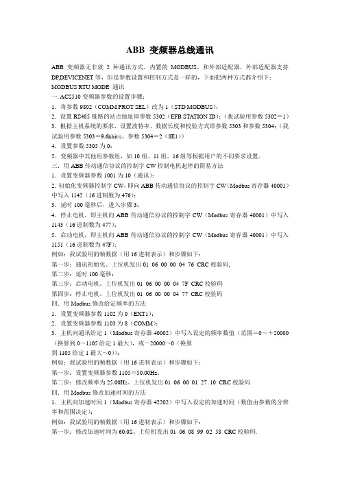
ABB 变频器总线通讯ABB变频器无非就2种通讯方式,内置的MODBUS,和外部适配器,外部适配器支持DP,DEVICENET等,但是参数设置和控制方式是一样的,下面把两种方式都介绍下:MODBUS RTU MODE 通讯一. ACS510变频器参数的设置步骤:1.将参数9802(COMM PROT SEL)改为1(STD MODBUS);2.设置RS485链路的站点地址即参数5302(EFB STATION ID);(我试验用参数5302=1)3.根据主机系统的要求,设置波特率、数据长度和校验方式即参数5303和参数5304;(我试验用参数5303=9.6kbit/s,参数5304=2(8E1))4.设置参数5305为0;5.变频器中其他组参数组,如10组、11组、16组等根据用户的不同要求设置。
三.用ABB传动通信协议的控制字CW控制电机起停的简易方法1.设置变频器参数1001为10(通讯);2.初始化变频器控制字CW,即向ABB传动通信协议的控制字CW(Modbus寄存器40001)中写入1142(16进制数为476);3.延时100毫秒后,进入步骤3;4.停止电机,即主机向ABB传动通信协议的控制字CW(Modbus寄存器40001)中写入1143(16进制数为477);5.启动电机,即主机向ABB传动通信协议的控制字CW(Modbus寄存器40001)中写入1151(16进制数为47F);例如:我试验用的帧数据(用16进制表示)和步骤如下:第一步:通讯初始化。
上位机发出01 06 00 00 04 76 CRC校验码,第二步:延时100毫秒;第三步:启动电机。
上位机发出01 06 00 00 04 7F CRC校验码第四步:停止电机。
上位机发出01 06 00 00 04 77 CRC校验码四.用Modbus修改给定频率的方法1.设置变频器参数1102为0(EXT1);2.设置变频器参数1103为8(COMM);3.主机向通讯给定1(Modbus寄存器40002)中写入设定的频率数值(范围=0~+20000(换算到0~1105给定1最大),或-20000~0(换算到1105给定1最大~0));例如:我试验用的帧数据(用16进制表示)和步骤如下:第一步:设置变频器参数1105=50.00Hz;第二步:修改频率为25.00Hz。
AB PLC通讯连接

104单元AB PLC用笔记本通讯联机过程
目的:
1、对AB PLC进行编程;
2、对AB PLC进行组态文件备份。
作业准备:
1、1747-PCI卡件及专用连接电缆
2、专用笔记本电脑
3、电源板
作业过程:
1、连接1747-PCI卡件到专用笔记本;
2、连接1747-PCI卡件到PLC通讯端口RS232;
3、打开笔记本上的RSLINE程序;
4、点击“communications”,弹出下拉菜单,选择“configurations driver”进入1747-PCI 卡驱动配;
5、选择可用的驱动类型“available driver type”,在其下拉菜单中选择“RS232 DF1 device”;
6、点击“configuration”进入详细配置:
6.1、com端口根据笔记本的端口属性选择;
6.2、波特率“baud rate”选择“9600”;
6.3、或者直接选择“Auto configuration”
6.4、点击“OK”完成设置。
7、打开“RSLogics 500 Pro”编程软件;
8、在“通讯c”的下拉菜单中选择“上载”从PLC中读取组态文件。
作业人员:陈文旭史承梅
2010年4月15日星期四吴志龙整理。
(仅供参考)AB 模块网络设置及连接

AB 模块网络设置及连接目录1 PLC (3)1.1 PLC的结构 (3)1.1.1 电源模块 (4)1.1.2 CPU (4)1.1.3 DeviceNet扫描器 (5)1.1.4 输入、输出模块 (5)1.1.2 PLC与设备间的联系 (6)2 网关 (8)2.1 网关的配置 (8)2.2 网关挂网 (9)3安全模块 (16)3.1 安全模块配置 (17)3.2 安全模块挂网 (17)4 变频器 (22)4.1 变频器结构 (22)4.2 变频器参数设定 (24)4.2.1 ATV312变频器参数设定 (24)4.2.2 ATV71变频器参数设定 (25)4.3 变频器挂网 (27)5 交换机 (30)5.1 交换机的设置 (30)6 读写头 (33)6.1 RFID配置 (33)6.2 实物连接图 (34)7 扫码枪 (35)7.1 CBX800控制盒 (35)7.1.1 CBX800内部布置图 (35)7.1.2 CBX800外部接线图 (36)7.1.3 CBX800的设置 (37)7.2 DS6400自动扫码器 (41)7.3 POWERSCAN扫描器 (46)1 PLC1.1 PLC的结构北汽总装车间PLC为AB的1756-L72系列,采用分布式控制架构,10插槽机箱。
从下面图1-1可以看出,PLC由8部分组成,第一个是电源模块,红色的是安全模块,第二个和第三个模块为CPU,第四个、第五个和第六个模块是DeviceNet扫描器(主站),第七个蓝色的是输入模块,第八个青色的是输出模块,它们与程序里是对应的(见图1-2)。
图1-1图1-21.1.1 电源模块电源模块是为PLC供电所用,上面有个旋钮,分别为测试模式、运行模式、Program模式,一般现场为运行模式。
若是模块上选择测试模式或者Program模式,那么程序里不能更改,如图1-3所示。
图1-31.1.2 CPUCPU是PLC的核心组件,这个模块可设置PLC地址,同时也可以与外部通讯。
1734-ACNR

Publication 1734-IN582B-EN-P - February 2005Installation InstructionsPOINT I/O ControlNet AdapterCatalog Number 1734-ACNRThe POINT I/O ControlNet Adapter is a communications adapter for POINT I/O modules. The adapter provides an interface forcontrolling and communicating with POINT I/O modules from a ControlNet network.4324743247A2Important User InformationBecause of the variety of uses for the products described in this publication, those responsible for the application and use of these products must satisfy themselves that all necessary steps have been taken to assure that each application and use meets all performance and safety requirements, including any applicable laws, regulations, codes and standards. In no event will Rockwell Automation be responsible or liable for indirect or consequential damage resulting from the use or application of these products.Any illustrations, charts, sample programs, and layout examples shown in this publication are intended solely for purposes of example. Since there are many variables and requirements associated with any particular installation, Rockwell Automation does not assume responsibility or liability (to include intellectual property liability) for actual use based upon the examples shown in this publication.Allen-Bradley publication SGI-1.1, Safety Guidelines for the Application, Installation and Maintenance of Solid-State Control (available from your local Rockwell Automation office), describes some important differences between solid-state equipment and electromechanical devices that should be taken into consideration when applying products such as those described in this publication. Reproduction of the contents of this copyrighted publication, in whole or part, without written permission of Rockwell Automation, is prohibited.Throughout this publication, notes may be used to make you aware of safety considerations. The following annotations and their accompanying statements help you to identify a potential hazard, avoid a potential hazard, and recognize the consequences of a potential hazard:Publication 1734-IN582B-EN-P - February 20053Publication 1734-IN582B-EN-P - February 2005Identifies information about practices or circumstances that can cause an explosion in a hazardous environment, which may lead to personal injury or death, property damage, oreconomic loss.Identifies information about practices orcircumstances that can lead to personal injury ordeath, property damage, or economic loss.Identifies information that is critical forsuccessful application and understanding of theproduct.SHOCK HAZARDLabels may be located on or inside the equipment(e.g., drive or motor) to alert people thatdangerous voltage may be present.4Environment and EnclosureThis equipment is intended for use in a PollutionDegree 2 industrial environment, in overvoltageCategory II applications (as defined in IECpublication 60664-1), at altitudes up to 2000meters without derating.This equipment is considered Group 1, Class Aindustrial equipment according to IEC/CISPRPublication 11. Without appropriate precautions,there may be potential difficulties ensuringelectromagnetic compatibility in otherenvironments due to conducted as well asradiated disturbance.This equipment is supplied as "open type"equipment. It must be mounted within anenclosure that is suitably designed for thosespecific environmental conditions that will bepresent and appropriately designed to preventpersonal injury resulting from accessibility to liveparts. The interior of the enclosure must beaccessible only by the use of a tool. Subsequentsections of this publication may contain additionalinformation regarding specific enclosure typeratings that are required to comply with certainproduct safety certifications.See NEMA Standards publication 250 and IECpublication 60529, as applicable, for explanationsof the degrees of protection provided by differenttypes of enclosure. Also, see the appropriatesections in this publication, as well as theAllen-Bradley publication 1770-4.1 ("IndustrialAutomation Wiring and Grounding Guidelines"),for additional installation requirements pertainingto this equipment.Publication 1734-IN582B-EN-P - February 20055Preventing Electrostatic DischargeThis equipment is sensitive to electrostatic discharge, which can cause internal damage and affect normal operation. Follow these guidelines when you handle this equipment:•Touch a grounded object to dischargepotential static.•Wear an approved grounding wriststrap.•Do not touch connectors or pins oncomponent boards.•Do not touch circuit components inside theequipment.•If available, use a static-safe workstation.•When not in use, store the equipment inappropriate static-safe packaging.POINT I/O is grounded through the DIN rail to chassis ground. Use zinc-plated, yellow-chromated steel DIN rail to assure proper grounding. Using other DIN rail materials (e.g., aluminum, plastic, etc.) which can corrode, oxidize or are poor conductors, can result in improper or intermittent platform grounding.When you connect or disconnect the Removable Terminal Block (RTB) with field side power applied, an electrical arc can occur. This could cause an explosion in hazardous location installations.Be sure that power is removed or the area is nonhazardous before proceeding.Publication 1734-IN582B-EN-P - February 20056Before You BeginTo effectively use your adapter, note the following considerations.Understand MessagingClass 3 (Explicit Message) requests through the 1734-ACNR adapter to a specific POINT I/O module may not always receive a response from the I/O module. In the case where the I/O module does not reply to the request, the adapter responds with an error code indicating a time-out.Establish I/O ConnectionsWhen you power up a POINT I/O system and establish I/O connections, the outputs transition to the Idle state, applying Idle state data before going to RUN mode. This occurs even when the controller making the connection is already in RUN mode. Configure AutobaudThe adapter cannot reconfigure an I/O module that you previously configured to operate at a fixed baud rate. When you reuse a POINT I/O module from another POINT I/O system, configure the module to autobaud before using it with the 1734-ACNR adapter.For More InformationThe following related publications are available online at URL .Publication Publication NumberPOINT I/O ControlNet Adapter User Manual1734-UM008POINT I/O ControlNet Adapter Release Notes 1734-RN004 Publication 1734-IN582B-EN-P - February 20057 Install the ControlNet AdapterYou must use Series C Point I/O modules with the1734-ACNR. Series A and B Point I/O modules willnot work with the 1734-ACNR.To install the adapter on the DIN rail prior to installing other base units, proceed as follows.1.Position the adapter vertically above the DIN rail.2.Press down firmly to install the adapter on the DIN rail. Thelocking mechanism will lock the adapter to the DIN rail.3.Set the node address on the node address thumbwheel.If you connect or disconnect the ControlNetcable with power applied to this module or anydevice on the network, an electrical arc canoccur. This could cause an explosion inhazardous location installations.Be sure that power is removed or the area isnonhazardous before proceeding.4.Remove the safety end cap by sliding it up. This exposes thebackplane and power interconnections.Do not discard the end cap. Use this end cap tocover the exposed interconnections on the lastmounting base on the DIN rail. Failure to do socould result in equipment damage or injury fromelectric shock.Publication 1734-IN582B-EN-P - February 20058Publication 1734-IN582B-EN-P - February 2005Set the Node AddressSet the node address using the 2-position thumbwheel switch. Valid settings range from 01 to 99. Press the + or - buttons to change theWARNING When you insert or remove the module whilebackplane power is on, an electrical arc can occur.This could cause an explosion in hazardouslocation installations.Be sure that power is removed or the area isnonhazardous before proceeding. Repeatedelectrical arcing causes excessive wear to contactson both the module and its mating connector.Worn contacts may create electrical resistance thatcan affect module operation.91.Remove the existing adapter from the DIN rail as follows:a.Disconnect the ControlNet connector from the adapter.b.Pull up on the RTB removal handle to remove the terminalblock.c.Remove the adjacent module from its base.e a small bladed screwdriver to rotate the DIN raillocking screw to a vertical position. This releases thelocking mechanism.e.Lift straight up to remove2.Remove the safety end cap on the replacement adapter bysliding it up. This exposes the backplane and powerconnections.3.Position the replacement adapter vertically above the DIN rail.(Make certain the DIN rail lock is in the horizontal position.) Slide the adapter down, allowing the interlocking side pieces to engage the adjacent module.4.Press firmly to seat the adapter on the DIN rail. The adapterlocking mechanism will snap into place.5.Set the node address on the node address thumbwheel.6.Insert the end opposite the handle into the base unit. This endhas a curved section that engages with the wiring base.7.Rotate the terminal block into the wiring base until it locksitself into place.8.Replace the adjacent module in its base.9.Connect the ControlNet cable to the adapter. Use a tap toconnect the adapter to the ControlNet cable. Do not directly connect the adapter to the coax cable.Publication 1734-IN582B-EN-P - February 200510Wire the ControlNet AdapterIf you connect or disconnect the communicationscable with power applied to this module or anydevice on the network, an electrical arc can occur.This could cause an explosion in hazardouslocation installations.If you connect or disconnect wiring while thefield-side power is on, an electrical arc can occur.This could cause an explosion in hazardouslocation installations. Be sure that power isremoved or the area is nonhazardous beforeproceeding.Publication 1734-IN582B-EN-P - February 200543264NC = No ConnectionCoaxialCoaxialNetwork30880NC = No ConnectionC =NC NCC VVC V dcCHAS CHAS 357124612/24VDo not connect 120/240V acThis dc supply will be connected toOff No power applied to device Alternating Red/Green LED powerup test (module self-test) Flashing Red Recoverable fault has occurred:Firmware (NVS) updateMAC ID changedCPU load exceededSolid Red Unrecoverable fault has occurred:self test failure (checksum failure at powerup, ramtest failure atpowerup)firmware fatal errorFlashing Green Waiting for connection or ControlNet cable breakSolid Green Module is operating correctly (normal mode)ControlNet A/B StatusViewed TogetherBoth Steady Off Reset, no power or entire network interface deactivated Alternating Red/Green Self test modeAlternating Red/Off Bad/invalid node configuration (such as duplicate MAC ID) Both Steady Red Failed link interfaceViewed IndividuallySteady Off Channel disabled or channel not supportedFlashing Red/Green Invalid link configurationFlashing Red/Off Severe Link error - link fault or no MAC frames received Flashing Green/Off Temporary channel error or listen-onlySteady Green Normal operation - MAC frames are being received withoutdetected errorsPointBus StatusOff Device not powered - check module status indicator Alternating Red/Green LED powerup testFlashing Red Recoverable fault has occurred:•at power up the number of expected modules does notequal the number of modules present• a module is missing•node fault (I/O connection timeout)Red Unrecoverable fault has occurred:•The adapter is bus off•The adapter has failed its duplicate MAC ID check Flashing Green Adapter on-line with no connections established•adapter chassis size has not been configured•controller in program/idle mode•ControlNet cable breakGreen Adapter on-line with connections established (normaloperation, in run mode)ControlNet A/B StatusViewed TogetherBoth Steady Off Reset, no power or entire network interface deactivated Alternating Red/Green Self test modeAlternating Red/Off Bad/invalid node configuration (such as duplicate MAC ID) Both Steady Red Failed link interfaceNorth American Hazardous Location ApprovalThe following information applies when operating this equipment in hazardous locations:Informations sur l’utilisation de cet équipement en environnements dangereux :Products marked “CL I, DIV 2, GP A, B, C, D” are suitable for use in Class I Division 2 Groups A, B, C, D, Hazardous Locations and nonhazardous locations only. Each product is supplied with markings on the rating nameplate indicating the hazardous location temperature code. When combining products within a system, the most adverse temperature code (lowest “T” number) may be used to help determine the overall temperature code of the system. Combinations of equipment in your system are subject to investigation by the local Authority Having Jurisdiction at the time of installation.Les produits marqués "CL I, DIV 2, GP A, B, C, D" ne conviennent qu’à une utilisation en environnements de Classe I Division 2 Groupes A, B, C, D dangereux et non dangereux. Chaque produit est livré avec des marquages sur sa plaque d’identification qui indiquent le code detempérature pour les environnements dangereux. Lorsque plusieurs produits sont combinés dans un système, le code de température le plus défavorable (code de température le plus faible) peut être utilisé pour déterminer le code de température global du système. Les combinaisonsd’équipements dans le système sont sujettes à inspection par les autorités locales qualifiées au moment del’installation.EXPLOSION HAZARD•Do not disconnectequipment unless powerhas been removed or thearea is known to benonhazardous.•Do not disconnectconnections to thisequipment unless powerhas been removed or thearea is known to benonhazardous. Secure anyexternal connections thatmate to this equipment byusing screws, slidinglatches, threadedconnectors, or other meansprovided with this product.•Substitution of components may impair suitability forClass I, Division 2.•If this product containsbatteries, they must only bechanged in an area knownto be nonhazardous.RISQUE D’EXPLOSION •Couper le courant ous’assurer quel’environnement est classénon dangereux avant dedébrancher l'équipement.•Couper le courant ous'assurer quel’environnement est classénon dangereux avant dedébrancher lesconnecteurs. Fixer tous lesconnecteurs externesreliés à cet équipement àl'aide de vis, loquetscoulissants, connecteursfiletés ou autres moyensfournis avec ce produit.•La substitution decomposants peut rendrecet équipement inadapté àune utilisation enenvironnement de ClasseI, Division 2.•S’assurer quel’environnement est classénon dangereux avant dechanger les piles.European Hazardous Location ApprovalEuropean Zone 2 Certification (The following applies when the product bears the EEx Marking)This equipment is intended for use in potentially explosive atmospheres as defined by European Union Directive 94/9/EC.DEMKO certifies that this equipment has been found to comply with the Essential Health and Safety Requirements relating to the design and construction of Category 3 equipment intended for use in potentially explosive atmospheres, given in Annex II to this Directive. The examination and test results are recorded in confidential report No 03NK30347. Compliance with the Essential Health and Safety Requirements has been assured by compliance with EN 50021.Observe the following additional Zone 2 certification requirements.•This equipment is not resistant to sunlight or other sources ofUV radiation.•The secondary of a current transformer shall not beopen-circuited when applied in Class I, Zone 2 environments.•Equipment of lesser Enclosure Type Rating must be installed inan enclosure providing at least IP54 protection when appliedin Class I, Zone 2 environments.•This equipment shall be used within its specified ratingsdefined by Allen-Bradley.•Provision shall be made to prevent the rated voltage frombeing exceeded by transient disturbances of more than 40%when applied in Class I, Zone 2 environments.SpecificationsSpecifications - 1734-ACNR ControlNet AdapterExpansion I/O Capacity Maximum of 63 modulesMaximum of 5 Rack Optimized connections (for digitalmodules only)Maximum of 25 Direct connections1734-ACNR backplane current output = 1.0A maximum.See list following for backplane current consumption foreach Point I/O catalog number and current consumption foreach of the Point modules connected to the 1734-ACNR.Verify it is below 1.0A.Backplane current can be extended beyond 1.0A with a1734-EP24DC Backplane Extension Power Supply. The1734-EP24DC can supply up to an additional 1.3A ofbackplane current.Multiple 1734-EP24DC modules can be used to reach themaximum of 63 modules.Specifications - 1734-ACNR ControlNet Adapter (continued)Expansion I/O Capacity Cat. No.PointBus Current Requirements1734-IB275mA1734-IB475mA1734-IB875mA1734-IV275mA1734-IV475mA1734-OB275mA1734-OB475mA1734-OB875mA1734-OB2E75mA1734-OB2EP75mA1734-OB4E75mA1734-OB8E75mA1734-OV2E75mA1734-OV4E75mA1734-OW280mA1734-OX2100mA1734-IE2C75mA1734-OE2C75mA1734-IE2V75mA1734-OE2V75mA1734-IA275mA1734-IM275mA1734-OA275mA1734-IJ2160mA1734-IK2160mA1734-IR2220mA1734-IT2I175mA1734-SSI110mA1734-232ASC75mA1734-VHSC5180mA1734-VHSC24180mAControlNet Communication Rate5Mbits/s (fixed value)Module Location Starter module - left side of the 1734 systemPower Supply SpecificationsInput Voltage Rating24V dc nominal 10-28.8V dc rangeField Side Power Requirements24V dc (+20% = 28.8V dc maximum) @ 425mA maximum Inrush Current6A maximum for 10msInterruption Output voltage will stay within specifications when inputdrops out for 10ms at 10V with maximum load.General SpecificationsIndicators 4 red/green status indicatorsAdapter statusPointBus statusControlNet A statusControlNet B status2 green power supply status indicators:System Power (PointBus 5V powerField Power (24V from field supply)Power Consumption10.2W maximum @ 28.8V dcPower Dissipation 5.0W maximum @ 28.8VPointBus Output Current1A maximum @ 5V dc ±5% (4.75 - 5.25)Input Overvoltage Protection Reverse polarity protectedThermal Dissipation16.9 BTU/hr maximum @ 28.8V dcIsolation Voltage Tested to withstand 750Vac for 60sField Power BusNominal Voltage Supply Voltage Range Supply Current 24V dc10-28.8V dc range, 10A maximumDimensions Inches (Millimeters)3.0H x 2.16W x 5.25L (76.2H x 54.9W x 133.4L)ESD Immunity IEC 61000-4-2: 6kV contact discharges 8kV air discharges Radiated RF Immunity IEC 61000-4-3:10V/m with 1kHz sine-wave 80%AM from 30MHz to2000MHz10V/m with 200Hz 50% pulse 100%AM from 900MHz EFT/B Immunity IEC 61000-4-4:+4kV at 5.0kHz on power ports+2kV at 5.0kHz on communications portsSurge Transient Immunity IEC 61000-4-5:+1kV line-line(DM) and +2kV line-earth(CM) on power ports+2kV line-earth(CM) on communications ports Conducted RF Immunity IEC 61000-4-6:10Vrms with 1kHz sine-wave 80%AM from 150kHz to80MHzEmissions CISPR 11 Group 1, Class AEnclosure Type Rating None (open-style)Power Conductors Wire SizeControlNet ConductorsWiring Category1,214 AWG (2.5mm2) - 22 AWG (0.25mm2) solid or stranded copper wire rated at 75o C or higher 3/64 inch (1.2mm) insulation maximumSee Publication CNET-IN002A1 - on power ports2 - on communications portsTerminal Base Screw Torque7 pound-inches (0.6Nm) Mass9.0 oz/255 grams Publications - User Manual1734-UM00821Environmental ConditionsOperational Temperature IEC 60068-2-1 (Test Ad, Operating Cold),IEC 60068-2-2 (Test Bd, Operating Dry Heat),IEC 60068-2-14 (Test Nb, Operating Thermal Shock):-20 to 55°C (-4 to 131°F)Storage Temperature IEC 60068-2-1 (Test Ab, Unpackaged Nonoperating Cold),IEC 60068-2-2 (Test Bb, Unpackaged Nonoperating DryHeat),IEC 60068-2-14 (Test Na, Unpackaged NonoperatingThermal Shock): -40 to 85°C (-40 to 185°F) Relative Humidity IEC 60068-2-30 (Test Db, Unpackaged Nonoperating DampHeat): 5 to 95% noncondensingShock IEC 60068-2-27 (Test Ea, Unpackaged Shock)Operating30gNonoperating50gVibration IEC 60068-2-6 (Test Fc, Operating) 5g @ 10-500HzPublication 1734-IN582B-EN-P - February 200522Publication 1734-IN582B-EN-P - February 2005Certifications 3 (when product is marked)c-UL-us UL Listed for Class I, Division 2 Group A,B,C,D Hazardous Locations, certified for U.S. and Canada EE X European Union 94/9/EC ATEX Directive,compliant with:EN 50021; Potentially Explosive Atmospheres,Protection “n” (Zone 2)CE European Union 89/336/EEC EMC Directive,compliant with:EN 61000-6-4; Industrial EmissionsEN 50082-2; Industrial ImmunityEN 61326; Meas./Control/Lab., IndustrialRequirementsEN 61000-6-2; Industrial ImmunityC-Tick Australian Radiocommunications Act, compliant with:AS/NZS CISPR11; Industrial EmissionsCIControlNet Int’l conformance tested to ControlNet specifications 1Use this Conductor Category information for planning conductor routing. Refer to ‘IndustrialAutomation Wiring and Grounding Guidelines”, publication 1770-4.1.2 Use this Conductor Category information for planning conductor routing as described int heappropriate System Level Installatin manual.3See the Product Certification link at for Declarations of Conformity, Certificates, andother certification details.POINT I/O is a trademark of Rockwell Automation.ControlNet is a trademark of ControlNet International.23 Notes:Publication 1734-IN582B-EN-P - February 2005öPublication 1734-IN582B-EN-P - February 2005PN 957726-64Supersedes Publication 1734-IN582A-EN-P - December 2002Copyright © 2005 Rockwell Automation, Inc. All rights reserved. Printed in the U.S.A.Rockwell Automation SupportRockwell Automation provides technical information on the web to assist you in using its products. At , you can find technical manuals, a knowledge base of FAQs, technical and application notes, sample code and links to software service packs, and a MySupport feature that you can customize to make the best use of these tools.For an additional level of technical phone support for installation,configuration and troubleshooting, we offer TechConnect Support programs. For more information, contact your local distributor or Rockwell Automation representative, or visit .Installation AssistanceIf you experience a problem with a hardware module within the first 24 hours of installation, please review the information that's contained in this manual. You can also contact a special Customer Support number for initial help in getting your module up and running:New Product Satisfaction ReturnRockwell tests all of its products to ensure that they are fully operational when shipped from the manufacturing facility. However, if your product is not functioning and needs to be returned:United States1.440.646.3223 Monday – Friday, 8am – 5pm EST Outside United States Please contact your local Rockwell Automation representative for any technical support issues.United States Contact your distributor. You must provide a Customer Support case number (see phone number above to obtain one) to your distributor in order to complete the return process.Outside United StatesPlease contact your local Rockwell Automation representative for return procedure.。
AB变频器使用说明书
AB变频器使用说明书
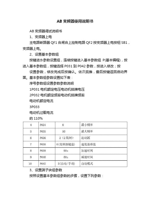
AB变频器调试说明书
1、变频器上电
主电路断路器QF1合闸合上控制电路QF2 按变频器上电按钮SB1,变频器上电。
2、设置基本参数组
按键进水参数设置组,连续按键进入基本参数组P(基本编程),按进入基本参数组,按键选择P031到P042参数,按进入修改;按设置参数,修改完成后按确认。
依次类推,最后按键返回启动界面。
基本参数组参数设置如下表:
序号参数组设置参数参数说明
1P031电机额定电压电动机铭牌电压
2P032电机额定频率电动机铭牌频率
电动机额定电流
3P033
电动机过载电流
的110%
3、设置端子块组参数
按照设置基本参数组参数的步骤,设置下列参数:
4、启动变频器
a
、当变频器控制柜“本地/远程”旋钮打到“本地”时,变频器通过柜门的“启
动”、“停止”按钮启动和停止变频器。
变频器通过面板
改变变频器的给定频率。
b、当变频器控制柜“本地/远程”旋钮打到“远程”时,变频器通过柜门的“启动”、“停止”按钮启动和停止变频器。
变频器通过触摸屏和上位机给定频率。
说明:本说明书中的参数设置是根据本公司设计的控制电路设置的,如果电路发生更改需要重新设置参数。
AB-PLC操作步骤

初次使用AB-PLC的操作步骤一·设置PLC的IP1. 用USB线(普通的打印机线)连接PLC,电脑会自动安装驱动。
2. 打开RSLinx Classic软件,界面如下:左边的浏览器里会自动生成一个USB项。
3. 点开USB项,会看到正在连接的PLC,右击PLC,选择属性,跳出画面如下:设置相应的IP地址,点击应用,最后确认OK,如下图显示。
也可以用网线在BOOTP/DHCP Server软件中进行修改IP,另外此软件还可以查看任意一款带以太网口的MAC地址。
这个软件在你装完AB软件之后,自动生成的。
二·怎么用网线更新下载PLC固件和程序1. 在刚刚打开的RSLinx Classic软件里,点击配置驱动,画面如下:选择EtherNet/IP Driver,点击Add New2. 点击完Add New按钮后,弹出一个对话框如下:选择相应的网口IP地址项,点击应用和OK。
3. 接下来将会在RSLinx Classic软件的右边浏览器里会看到正在连接的PLC,如下:4. 打开PLC程序,点击Communications,画面如下:5. 选中蓝色区域的PLC,再点Download按钮,会跳出更新固件的画面,如下图:6. 点击更新固件,此时跳出画面,让你选择相应的版本,直接点击Update,更新开始。
7. 在更新固件期间,禁止断电或拔掉网线。
8. 更新完成后,会自动跳出如下的下载画面,点击下载。
三·怎么在线修改PLC程序1. 下载完成后,选择运行模式,此时程序处于在线运行监控模式,最左边会看到绿色的能量流,画面如下:2. 先点击需要修改的程序行,点击上图中的红色区的键,此时蓝色区域里的绿色能量流变成了虚线,见下图:此时可以对此行进行修改,添加一个I1.1的常开,再点击向右的一个绿色箭头,修改程序将会下载到PLC里,同时虚线变成绿实线。
在线修改完成。
四·HMI程序的建立连接和下载1. 打开HMI程序,点击通信设置,跳出设置画面:按照红色字体的步骤1,2,3,4,5,6操作,完成通信设置。
AB品牌PLC操作说明
AB品牌PLC操作说明目录一、AB PLC模块选型 (2)二、软件安装................................................................................................... (4)RSLogix5000软件安装 (4)RSLinx2.55软件安装 (6)FactoryTalk View软件安装 (8)三、软件应用 (12)RSLogix5000的操作方法 (12)FactoryTalk View软件应用 (23)我公司最近使用了两套AB 品牌的1769L31的PLC ,现对其组态、编程、测试等需要注意的事项介绍如下:一、AB PLC 模块选型:AB PLC 根据不同用途大体可分为大型机(1756系列)、中型机(1769、1789系列)、小型机(1794系列)。
共有特点 1756 ControlLogix ™ 1769 CompactLogix ™ 1789 SoftLogix5800 ™ 1794 FlexLogix ™控制器任务 连续性 周期性 事件 • 32 (1 ) •• 1769-L35E 8 • 1769-L35CR 8 • 1769-L32E 6 • 1769-L32C 6 • 1769-L31 4 • 1• 32 ( 1 ) • Windows• 8 ( 1 ) •用户内存 1756-L55M12 750Kbytes1769-L31 512K1789-L10 2 Mbytes 3 1794-L33 64 Kbytes 1756-L55M13 1.5 Mbytes1769-L32E 750K无运动控制 1794-L34 512 Kbytes 1756-L55M14 3. 5 Mbytes1769-L35E 1.5M 1789-L30 64 Mbytes 5 1756-L55M16 7. 5 Mbytes1769-L32C 750K 1789-L60 64 Mbytes 16 1756-L55M22 750 Kbytes1769-L32CR 1.5M 1756-L55M23 1. 5 Mbytes1756-L55M24 3. 5Mbytes 1756- L61 2 Mbytes 1756- L62 4 Mbytes1756- L63 8 Mbytes非易失性内存 1756- L55M12 1769-L31CompactFlash1794-L331756- L55M13 1769-L32ECompactFlash 1794-L34 * 1756- L55M14 1769-L35ECompactFlash 1756- L55M16 1769-L32CCompactFlash1756- L55M221769-L35CR CompactFlash1756- L55M231756- L55M24 1756-L61CompactFlash 1756-L62CompactFlash1756-L63CompactFlash内置通讯口 1 RS-232 (DF1 ASCII)1769-L31 2 RS-232 (Chan1: DF1; Chan2: DF1 ASCII) 1769-L32E,-L35E 1 EtherNet/IP 1 RS-232(DF1,ASCII)1769-L32C, L35CR 1 ConrtolNet 1 RS-232(DF1,ASCII)取决于个人计算机 • 1 RS-232 (DF1 ASCII) • 2 1788表1选择控制器时,可根据用户要求或设备的需求来选择CPU 和I/O 模块。
ABPLC_冗余配置
ABPLC_冗余配置
冗余配置
1.前提,完成ENBT以太网模块的IP地址设置,固件升级,完成CPU模块CNBR控制网模
块的固件升级,完成冗余模块的固件升级。
2.修改程序将冗余功能打开,将程序下载到备用PLC,点击运行,正常后断电。
3.将同一程序下载到主PLC。
4.将备用PLC的同轴通讯网线连接,以太网网线连接,主备PLC 的冗余网线连接。
5.备用PLC送电,观察备用PLC的控制网模块状态灯显示,观察以太网模块指示灯显示,
观察以太网模块IP地址,正常为主PLC以太网模块IP地址+1。
比如主机以太网地址是100,备用以太网地址就是101。
如果地址没有自动+1。
那么冗余是不成功的,需要检查原因,直到地址能自动配置才表示冗余配置成功。
6.主从端PLC冗余配置成功后,到车控室重新扫网。
扫网步骤,1)将主从端PLC及IBP
盘PLC设置到编程工作状态。
2)扫描上层网。
3)扫描设备层。
7.扫网完成后,将PLC设置到工作状态,程序内的冗余提示灯显示为绿色表示冗余成功。
冗余灯显示为红色时,可将备用PLC断电后重新上电。
8.冗余测试,将主PLC控制网拆下,备用PLC自动切换为主PLC 则冗余成功。
主PLC冗余
模块显示prim,备PLC冗余模块显示sync后,方可进行第二次切换测试。
AB下位机配置过程
BOOTP-DHCP Server软件新的以太网通讯模块是没有IP地址的,该软件用于设置以太网通讯模块的IP地址,设置完IP地址以后存在以太网模块的IP地址是动态(掉电或重启会丢失)的,所以还需要在RSlinx中为其设置为静态IP。
双击为其设置ip设置完成后点击OKRSlinx软件用BOOTP-DHCP Server为网络通讯模块设置完IP地址后就可以用RSlinx来对PLC系统进行连接了。
1、打开RSlinx,新建一个连接点击configure drivers,弹出以下窗口为新建的连接命名:点击ok后设置IP地址:新建的连接会自动扫描出当前网络的所有硬件:设置静态IP地址:此处显示所有的drivers,通过以太网可以选择Ethernet devices,选择后点击add newrslogix5000软件1、打开rslogix5000软件,新建一个工程在以太网模块上点击右键选择moduleconfiguration将IP地址设置为静态,应用,确定2、配置IO设置CPU型号选择版本是否冗余CPU所在机架型号CPU的槽位配置完成后:3、配置控制器数据标签根据模块实际型号和所在机架的槽位配置IO,在backplane上点击右键添加模块双击进入,配置数据标签标签名数据类型选择数据类型定义数组Dim 0 1维Dim 1 2维Dim 2 3维建立以下两个标签数组4、添加程序段,编写程序新添加一段程序主程序编程环境给指令添加数据标签程序编写完成编程语言选择,默认梯形图即可程序编写区域,先选编写程序的行再点击想要输入的指令编程指令区,各指令含义参见PDF文档指令集介绍5、进行程序编译:编译当前打开程序段完全编译若程序编写完成后没有进行程序完全编译,在程序下载之前系统会自动进行编译,一般在程序编写完成后进行程序编译进行差错修改。
6、进行程序下载:通过通讯链路找CPU7、在线监测程序:在线程序上载程序下载升级固件选中CPU。
AB品牌PLC操作说明
AB品牌PLC操作说明AB品牌PLC操作说明1.介绍本文档是关于AB品牌PLC(Programmable Logic Controller,可编程逻辑控制器)的操作说明。
AB品牌PLC被广泛应用于工业自动化领域,用于控制和监视生产过程中的各种设备和机器。
本文档将详细介绍AB品牌PLC的使用方法和注意事项,以帮助用户更好地了解和操作设备。
2.硬件配置2.1 CPU模块2.1.1 选取适当的CPU模块2.1.2 安装和连接CPU模块2.2 输入输出模块2.2.1 选取适当的输入输出模块2.2.2 安装和连接输入输出模块2.3 通信模块2.3.1 选取适当的通信模块2.3.2 安装和连接通信模块3.软件配置3.1 安装PLC编程软件3.2 创建新项目3.3 导入硬件配置3.4 编写逻辑程序3.5 程序到PLC3.6 调试和监控程序4.PLC操作4.1 启动和停止PLC4.2 程序的调用和运行4.3 监视和调试程序4.4 异常处理5.注意事项5.1 安全操作5.2 防止电气干扰5.3 温度和湿度要求5.4 维护和保养6.附件本文档附带以下附件:附件1:AB品牌PLC硬件配置手册附件2:AB品牌PLC编程软件安装指南附件3:AB品牌PLC使用示例7.法律名词及注释7.1 可编程逻辑控制器(PLC):一种用于自动化控制的电子设备,它能够根据预设的逻辑程序对输入和输出进行控制。
7.2 CPU模块:可编程逻辑控制器中的核心处理单元,负责执行逻辑程序并管理其他模块的交互。
7.3 输入输出模块:用于接收和发送外部信号的模块,将输入信号转换为逻辑控制器可识别的形式,并将输出信号传输到外部设备。
7.4 通信模块:用于与其他设备进行通信的模块,可以通过各种通信协议和接口与其他设备进行数据交换。
- 1、下载文档前请自行甄别文档内容的完整性,平台不提供额外的编辑、内容补充、找答案等附加服务。
- 2、"仅部分预览"的文档,不可在线预览部分如存在完整性等问题,可反馈申请退款(可完整预览的文档不适用该条件!)。
- 3、如文档侵犯您的权益,请联系客服反馈,我们会尽快为您处理(人工客服工作时间:9:00-18:30)。
【最新整理,下载后即可编辑】
【最新整理,下载后即可编辑】
AB 1734总线配置流程
问题描述:
总线配置是建立控制网络的基础,也是前期必须完成的工
作,在AB控制系统里,现场都使用了很多1734模块,及其下挂
的输入输出模块,所以学会1734的网络配置是很有必要的,在
今后自己添加模块是十分有用的。
网络配置都是通过软件RSNetWorx for DeviceNet,线对整体
网络进行扫描,将所有的网络节点都扫描上来,然后一个一个地
对其进行配置。
下面就介绍一下1734总线的配置流程:
以下是宝骏总装内饰线DeviceNet1下节点号为24的一个1734
模块的配置流程。
一、 通过软件RSNetWorx for DeviceNet扫描DNB模块下挂的
1734总线站点NODE 24,此层网络为主网络1756DNB。
二、 双击扫描到的总线站点NODE 24,点击Parameters选项,
将属性1---5项属性分别设置如下:(如果主网是DNB模块,
该项不必设置,该项设置主要用于波特率调整。)
【最新整理,下载后即可编辑】
三、 在不关闭软件RSNetWorx for DeviceNet的情况下,另外打
开软件RSNetWorx for DeviceNet。选择对应的1734总线站点
NODE 24,然后扫描1734总线站点NODE 24的子网络。如
下图,其中node00为子网的ADN,node01--02为子网输入模
块,node03为子网输出模块。
四、在子网画面里,双击子网的ADN-即node00。在ADN 里,对
模块node01—03进行配置,过程如下:
1、将node01—03添加到Scanlist里面。
【最新整理,下载后即可编辑】
2、将输入模块node01--02映射到Input里面。由于输出模块node03
也包含有状态信息,故在映射到Input的时候,需要将node03的
输入信息取消映射。同时记录下映射后的输入字节数,如下为4
个字节。
3、将输出模块node03映射到Output里面。同时记录下映射后
的输出字节数,如下为3个字节。
2个状态字;2个实际字(所
以后面在1756DNB模块里
配置该1734模块参数时,
input里就是“4”
【最新整理,下载后即可编辑】
设置完成后,将配置“Download”到现场模块里(下载下
去后DNB模块会报警,因为该配置与DNB里配置不一样,属
于正常报警。)下载完成后,将配置另存为
五、切换到主网络里面,对主网络1756DNB进行配置。
1、双击主网络1756DNB,即NODE00。在Scanlist里面将子网
1734ADN ,即站点node24添加到Scanlist里面。并手动填写字
节数,即把刚才记录下来的输入输出字节数填写到里面。
2、映射对应的Input。
2个状态字;1个实际字
(所以后面在1756DNB
模块里配置该1734模块
参数时,output里就是“3”
Input为4
Output为3
【最新整理,下载后即可编辑】
3、映射对应的Output。
地址的分配是根据实际情况进行划分,该1734分配的地址
为Data[63]。输入输出的起始地址一样,但是由于字节数不一样,
所以所占的字节长度也不一样。
配置完后点击“确定”保存就可以了。
六、将主网络及子网络全部配置成功后,作一下检查及测试
1、查看DNB模块报警状态,看看上述是否配置错误。例如
是否报故障77---字节数不匹配等。
地址Data63,从0
位开始
地址Data63,从0
位开始
【最新整理,下载后即可编辑】
2、打开PLC程序,在程序里查找对应的点,随机选择几个
点进行测试,验证是否正确。
七、如果以上步骤均已完成,并正确无误,说明1734总线配置
OK
地址Data63,对应的就是之
前配置的地址,里面的点就
是已经配置好的。