F4 AF手册-空中加油-by merlin翻译
飞控手册(英文原版)

飞控⼿册(英⽂原版)en/FlightCtrlManualThis page as PDF-File ? Just click on the right icon and wait some seconds (10-20 sec)...siehe auch: BL-Ctrl_Anleitung1.Flight-Ctrl V1.0: Schematic, Parts Soldering and Getting Started1.Tasks2.Other Features: 2.Micro Controller1.Gyro Sensors2.Acceleration Sensor3.Atmospheric pressure sensor4.Interfaces5.PPM input6.I2C Bus7.Serial Interface (asynchronous) 8.ISP Interface (synchronous) /doc/8f9ec01b10a6f524ccbf857d.html pass connection 3.General security notes1.Conditions of use 4.Setting up the board1.Step 1: Connection and Control of the supply voltage2.Step 2: Gyro Amplifier Calibration3.Step 3: Programming with the MikroKopter Tool (avrdude)4.Step 4: Hardware Test1.Test of sensor values2.Test of gyro and acceleration sensor data3.Test of the Rx signal4.Test of the voltage measurement5.Step 5: Installation into the MikroKopter1.Synopsis of the connection of other components2.Short form:3.Connections:6.Step 6: Control of the MikroKopter (short form)1.Switching on2.Calibration of the sensors and choice of setting3.Switching off the motors4.Behaviour when loosing Tx or Rx signal 7.Parts soldering 8.Tools & supplies 9.Soldering5.Placement plan with color support6.SchematicTasksThis board is the MikroKopter ’s control board . It fulfils the following tasks:l measuring the angular velocity of the three axes l measuring the acceleration data of the three axeslmeasuring the atmospheric pressure for altitude controlSeite in deutschl evaluation of a digital compass signall measuring the battery voltagel evaluation of the R/C signall processing of sensor data and computing the actual angular positionl driving four Brushless ESCs (electronic speed controllers)Other Features:l Dimensions 50 * 50mml Two LEDs (e.g. Okay & Error)l Two transistor outputs for external lights (or other functions)l Undervoltage detectionl A receiver can be powered by 5V****************************************************************************************** processor.The criteria for the choice of the micro controller were:l satisfactory performancel good availabilityl low costl easy to solderl availability of free development software SensorsThe flight attitude of a quadrocopter must be controlled electronically. We need different sensors for this.Gyro SensorsThey measure the angular velocity (rotational speed) of each axis. We need three sensors to stabilize all three axes. These sensors are the most elementary components (-> GyroScope )Acceleration SensorThe main function of the acceleration sensor is to measure the actual tilt of the MikroKopter and to support the altitude adjustment.Here we use a three axis sensor.Theoretically we could omit this sensor if the quadrocopter should work in the so called Heading-Hold-Mode. ( --> Acceleration Sensor ) Atmospheric pressure sensorIt serves to stabilize the flight altitude. This sensor is optional. The large pressure openings should be closed with adhesive tape where we make a tiny hole with a needle. This protects from false readings due to wind and light. (--> en/heightsensor ) Airpressure sensor at high altitude: If the Mikrokopter is going to be flown at very high altitudes (eg 2500 meters), then it is possible that the airpressure sensor will not operate correctly. The resistors have been calculated for airpressures of 850 to 1100 hpa. At 2500 metes the airpressure will be about 750 hpa. to correct this, solder a 1.5 (to 4.7) kOhm resistor (value dependent upon altitude) parallel to R21. InterfacesThe controller board communicates with the outside world through different interfaces.PPM inputHere we connect the receiver. Two wires for the supply voltage and one for the receiver’s R/C sum signal. Compared to a normal servo PPM signal the sum signal contains all the channels sent by the R/C transmitter before they are decoded by the receiver. This signal is available in every receiver but there are only a few where this signal is directly accessible from outside (e.g. the RX3 Multi by ACT). ( --> RC receiver )I2C BusWe connect the BL-ESCs to this bus, which carries the command sequences. The Flight-Ctrl needs our special brushless ESC, to ensure fast communication via the I2C Bus. Standard ESCs cannot be used as they are to slow. The I2C Bus has a clock (SCL) and data (SDA) line. The bus connects all SCL and SDA lines together.Serial Interface (asynchronous)Here we connect a PC for testing and calibration. The signal is TTL and not V24. For this reason we need to connect an interface converter if we want to communicate with the standard serial interface of the PC. Later on this interface can also be used for the communication (asynchronous) with other controllers.ISP Interface (synchronous)The ATMEL controller will be programmed via an ISP interface. This interface can be also be used for a fast communication (synchronous serial) with other controllers.Compass connectionA digital compass can be connected to the PC4 input of the universal connector.We do not guarantee an error free behaviour of the electronics or the software. Despite thoroughful design and verification we will not be held responsable (directly or indirectly) for the flawlessness of the software, the hardware or the informations included. You use the electronics at your own risk (this is also applicable for the PC software delivered). Further on we deny any responsability for colateral damages of goods or people which could arise from the use of this application. It is your own responsability to make a complete system test.The MikroKopter is not a children’s toy. It is too expensive and too dangerous for this. Do not fly over people!In any case you should contract a special model airplane insurance before the first flight because most ordinary liability insurances will not cover damages caused by model airplanes.Conditions of useThe use of the whole or parts of the MikroKopter project (hardware, software and documentation) is only allowed for private (non-commercial) use. If you intend a direct or indirect commercial use please contact us for conditions.Step 1: Connection and Control of the supply voltageBefore powering up you should once again check the correct position of the voltage regulator IC4 (µA7805) and the diodeD1. The supply voltage is connected to the pad J1 (marked …+“ at the switch) and to the pad J2 (marked …-“ close to theswitch). It is strongly advised to use a current limited power supply until you know that everything is working correctly. The supply current for the Flight-Ctrl board plus the four BL ESCs is about 200 mA.5,0V Test of the digital supply. Check at TP1 to GND. Voltage should be between 4,9 and 5,1 V.3,0V Test of the analog supply. Check at TP2 to GND. Voltage should be between 2,9 and 3,1 V.Step 2: Gyro Amplifier CalibrationThe outputs of the gyro amp (Pins 8, 7 and 1 of IC2) should show a voltage of about 1,2-1,8V (ideal value would be 1,5V) in idle state (board/copter not moving). The factory adjusted output signal of the gyros may vary slightly, we must therefore sometimes correct the signal.We need to add the resistors R9 (for TP4), R13 (for TP5) and R17 (for TP3) to increase the value of the signal (the lower the value of the resistor, the higher the output signal). Or we need to add the resistors R29 (for TP4), R20 (for TP5) und R15 (for TP3) to lower the signal (the lower the value of the resistor, the lower the output signal).Default values for the calibration resistors:Increasing the amplifier signal: signal value < 0,8V : 150kOhm < 1,0V : 220kOhm < 1,2V : 470kOhmLowering the amplifier signal: signal value > 2,2V : 150kOhm > 2,0V : 220kOhm > 1,8V : 470kOhmAfter a severe crash or irregular movements of the MikroKopter (e.g. pitch is smoother in one direction than the other) the signal should be checked and recalibrated if needed.Step 3: Programming with the MikroKopter Tool (avrdude)The software transfer (In System Programming) is easiest with our serial converter (SerCon), which contains already an ISP circuit. The PC must have a “real“ serial interface for programming. USB to serial/parallel converters or similar adaptors are definitively not working! The serial converter is connected to the 6 pin header with a ribbon cable. The LED on the converter board will be in an indifferent state (on or off). The Flight-Ctrl board must be connected to the supply voltage for programming. As an alternative the software can be programmed via USB with an AVR ISP mkII. The description is available under USB-AVRISPmkII. Another possibility for a later data communication via USB is the USB-TTL-232 adaptor.A boot loader is now available for the Flight-Ctrl. Instructions for programming can be found under MikroKopterTool...Step 4: Hardware TestTest of sensor valuesWhen the controller has been successfully programmed, you can check the sensor values with the MikroKopter tool. For this procedure you connect the serial converter with the large ribbon cable. The ISP cable must be disconnected for debugging or the jumper must be removed from the converter board.Test of gyro and acceleration sensor dataThe board must be put in a horizontal position and switched on (or reset), then start the scope option in the MikroKopter tool (if the scope was already running you should stop it for a moment to reset the zoom range). We observe here only the first five analog values. The other analog values can be switched off via the tab …Scope“ in the MikroKopter tool if the display becomes to difficult to read.Now you tilt the board as smoothly as possible to about 45 degrees in direction of the pitch axis. On the scope you check the signal values. The signal of the pitch integral and the pitch acceleration sensor (here red and yellow) should show a significant value.It is important that the overlaid graphs are identical as far as possible.The same check has to be made on the roll axis (here blue and green):Then we check the yaw gyro. For this purpose we turn the board around the yaw axis and observe the signal of the gyro. As long as we turn the board there will be a value > 0 which will come back to zero when we stop moving the board.We check the offset values of the gyros in the virtual display (the values in parenthesis):For this purpose we click through the buttons in the corresponding menu. The offset values should be around 500 (+-100). In this example the yaw gyro has a problem (178). It must be recalibrated or changed.Test of the Rx signalIn the virtual display we can read the R/C values:With the R/C control we can adjust the values in the range of ca. -120 to +120.Test of the voltage measurementIn this menu you can check the value of the voltage measurement:In this example we have 11,3V.The Rx level is 0 because no receiver was connected.Step 5: Installation into the MikroKopterMore information on our homepageSynopsis of the connection of other componentsShort form:l The arrow on the mounted Flight-Ctrl board points in flight directionl Addressing the motors : 1=front 2=back 3=right 4=leftl The direction of rotation of the motors: the left and right motor (roll axis) turn counter clockwise (seen from above) and the front and back motor (pitch axis) turn clockwise.Connections:l the multi signal from the receiver with a 3 wire servo cablel a LiPo battery (11,1V ca. 1,5-2,5Ah dischargeable with 15-20C) with two wires of 0.75mm2 minimum (positive=red; negative=black)l four BL-ESCs with two supply wires of 0.75mm2 minimum (positive=red; negative=black)l I2C Bus for the communication with the Brushless-ESCsDetails of the whole construction see ElektronikVerkabelung....Step 6: Control of the MikroKopter (short form)Switching onThe MikroKopter must sit level on a rigid support. The green LED of the Flight-Ctrl is on, the red is off and the beeper is silent. The green LEDs of the BL-ESCs are on, the reds are off. If the beeper beeps the reception is jammed or the voltage of the battery is too low.Calibration of the sensors and choice of settingRemark: this description is applicable for throttle not inverted: throttle minimal = pointed TO the pilot 'For the calibration of the sensors push the throttle/yaw lever to the upper left corner until the beeper beeps and the green LED goes off. This way the controller regards the current gyro values as "levelled". The beeper will tell you which "setting" is currently active. There are 5 possible settings. During the calibration as just described you can choose the appropriatesetting with thepitch/roll lever like this:2 3 41 x 5- - -Meaning: Pitch-Roll lever left middle = Setting1 ; left upper = Setting2 and so on.l To start push the throttle/yaw lever to the lower right corner until the motors startl The levelling control starts working from a certain throttle value only.Switching off the motorsPush the throttle/yaw lever to the lower left corner until the motors stop.Here you will find a video demo of how to start the motors, calibrate (1 beep confirms setting1), and stop the motors. Behaviour when loosing Tx or Rx signalIf the Rx signal gets lost during the flight the motors will continue to turn for a few seconds while the MikroKopter tries to get in a horizontal position. This should (more or less) allow for a controlled descent of the quadrocopter.Parts solderingThe parts should be soldered in the same order as shown in the listing. This simplifies the task. Parts in italics are placed on the solder side (bottom) 'Gyros, acceleration & pressure sensors are available in the ShopQty Reichelt Order# Remark Part Name 1 ATMEGA 644-20 AUCheck origin AVR-RISC-Controller IC1 1 TS 914 I SMD Check originRail to Rail Op-Amp IC25 NPO-G0805 22P Capacitor C1, C2, C28, C29,C30 5X7R-G0805 22NCapacitor C9, C15, C17, C27, C3117 X7R-G0805 100N CapacitorC5, C6, C8, C12, C13, C16, C18, C19, C20, C21, C11, C22, C14, C23, C24, C25, C265 SMD-0805 1,00K SMD-Chip-resistor R2, R5, R6, R7, R4 5 SMD-0805 100 SMD-Chip-resistor R24, R27, R28, R32, R33 5 SMD-0805 10,0K SMD-Chip-resistor R8, R12, R16, R1, R3 4 SMD-0805 100K SMD-Chip-resistor R10,R11, R14, R18 1 SMD-0805 220K SMD-Chip-resistor R26 1 SMD-0805 2,20K SMD-Chip-resistor R25 1 SMD-0805 6,80K SMD-Chip-resistor R213 SMD-0805 18,0K SMD-Chip-resistor R22, R30, R31 1 SMD-0805 680SMD-Chip-resistor R19 1 SMD-LED 0805 GN Arrow on bottom CHIP-LED green LED1 1 SMD-LED 0805 RT Arrow on bottom CHIP-LED red LED2 2 BC 817-25 SMD Check directionCHIP-Transistor T1, T2 1 LQH3C 100µ SMD-Inductor L1 1 -- Short with wire omitted C3 1 1N 4001Check marking DiodeD1 1 20,0000-HC49U-S Quartz 20,0MHz Q1 1 LP 2950 ACZ3,0 Check marking Voltage regulator +3,0VIC5 1 µA 7805 Check marking Voltage regulator IC4 2 RAD 330/16 Check polarity Electrolytic cap C7, C101 MS 500F Solder to the rim Switch, 2-pole SW1 use wire if necessary 1 SL 2X10G 2,54 Divide in 2*3 and 2*5 Header two rows SV1, SV5 1SUMMER TDB 05Polarity: (+) to the rim of the board BeeperSP1Sensors1 LIS3L02AS4 Acceleration sensor IC32 ENC-03JA Check direction Gyros Pitch and Roll GY_N, GY_R 1ENC-03JACheck direction Gyro Yaw GY_GOption for altitude adjustm. 1 MPX 4115A Metal plane to the board Motorola pressure sensorV111uF SMD1206Not available @Reichelt /alternative:Z5U-5 1,0µ(with wires)C4Resistors to adjust the gyrosignals 3 SMD-0805 470K See instructions SMD-Chip-resistor 3 SMD-0805 150K See instructions SMD-Chip-resistor 3 SMD-0805 220KSee instructionsSMD-Chip-resistorTools & suppliesl Edsyn FL 22 SMD-Fluxl Solder wick 1,5mml Solder AG 0,507 0,5mml Temperature controlled soldering station with fine tipl MultimeterSolderingThe yaw gyro must be soldered like shown: (JPN marking to the board)The pins on top must be extended with pieces of wire.The gyro should also be glued to the board to increase mechanical rigidness. Under no circumstances should glue penetrate into the gyros(equally coloured parts are identical)(click for high resolution) 'Translation by french-copter 2007-07-21. Please bear with me, I’m not a native speaker of English, if you find weird phrases or simply balderdash tell me…KategorieAnleitung, KategorieEnglishMikroKopter: en/FlightCtrlManual (zuletzt ge?ndert am 10.03.2009 17:27 durch JiPsi)。
飞行术语(中英对照)

飞行术语(中英对照)飞行术语1、the airframe 机身,结构2、The front (fore) part 前部3、The rear (aft) part 后部4、port 左旋(舵)5、starboard 右旋(舵)6、the inboard engine or inboards 内侧发动机7、the outboard engine or outboards 外侧发动机 8、the nose 机头9、the belly 腹部10、the skin 蒙皮11、the windscreen or windshield 风挡12、the wing 机翼13、the trailing edge 机翼后缘14、the leading edge 机翼前缘15、the wing tip 翼尖16、the control surface 操纵面17、ailerons 副翼18、flaps (inboard flap,outboard flap,leading edge flaps)襟翼(内侧襟翼,外侧襟翼,前缘缝翼)19、spoilers (inboard\outboard spoiler)(spoiler down\up)阻力板,扰流板(内、外侧扰流板)(扰流板放下、打开)20、slats 缝翼21、elevators (elevator control tab) 升降舵(升降舵操纵片)22、rudder (rudder control tab) 方向舵(方向舵操纵片)23、flap angle 襟翼角24、flap setting 襟翼调整25、the full flap position 全襟翼位置26、a flapless landing 无襟翼着陆27、the landing gear 起落架28、stabilizer 安定面29、the nose wheel 前轮30、gear locked 起落架锁定31、the wheel well 起落架舱32、the wheel door 起落架舱门33、a tyre 轮胎34、to burst 爆破35、a deflated tyre 放了气的轮胎36、a flat tyre 走了气的轮胎37、a puncture 轮胎被扎破38、to extend the flaps (to retract the flaps) 放下襟翼(收上襟翼)39、gear extention (gear retraction) 起落架放下(起落架收上)40、The gear is jammed. 起落架被卡死。
☆F16飞行员培训手册3-2(英文原版)

BY ORDER OF THE SECRETARY OF THE AIR FORCE AIR FORCE INSTRUCTION 11-2F-16VOLUME 220 JUNE 2006Flying OperationsF-16--AIRCREW EVALUATION CRITERIACOMPLIANCE WITH THIS PUBLICATION IS MANDATORY ACCESSIBILITY: Publications and forms are available on the e-Publishing website at for downloading or ordering.RELEASABILITY: There are no releasability restrictions on this publication.OPR:HQ ACC/A3TV Certified by:HQ USAF/ A3O(Brig Gen Robert C. Kane) Supersedes AFI 11-2F-16, V olume 2,15 March 2001Pages:64This volume implements AFPD 11-2, Aircraft Rules and Procedures; AFPD 11-4, Aviation Service; and AFI 11-202V2, Aircrew Standardization/Evaluation Program. It applies to all F-16 units. This instruction does apply to Air National Guard (ANG) and Air Force Reserve Command (AFRC). MAJCOMs/DRUs/ FOAs are to forward proposed MAJCOM/DRU/FOA-level supplements to this volume to HQ USAF/ A3OT, through HQ ACC/A3TV, for approval prior to publication in accordance with (IAW) AFPD 11-2, paragraph 4.2. Copies of MAJCOM/DRU/FOA-level supplements, after approved and published, will be provided by the issuing MAJCOM/DRU/FOA to HQ USAF/A3OT, HQ ACC/A3TV, and the user MAJ-COM/DRU/FOA and National Guard Bureau offices of primary responsibility. Field units below MAJ-COM/DRU/FOA level will forward copies of their supplements to this publication to their parent MAJCOM/DRU/FOA office of primary responsibility for post publication review. NOTE: The terms Direct Reporting Unit (DRU) and Field Operating Agency (FOA) as used in this paragraph refer only to those DRUs/FOAs that report directly to HQ USAF. Keep supplements current by complying with AFI 33-360V1, Air Force Content Management Program—Publications. See paragraph 1.2. of this volume for guidance on submitting comments and suggesting improvements to this publication.This publication requires the collection and or maintenance of information protected by the Privacy Act (PA) of 1974. The authorities to collect and or maintain the records prescribed in this publication are Title 10, United States Code, Chapter 857 and Executive Order 9397, Numbering System for Federal Accounts Relating to Individual Persons, November 22, 1943. Forms affected by the PA have an appropriate PA statement. System of records notice F011 AF XO A, Aviation Resource Management System (ARMS) (December 26, 2002, 67 FR 78777) applies. Paperwork Reduction Act of 1974 as amended in 1996 affects this instruction. Ensure that all records created as a result of processes prescribed in this publica-tion are maintained in accordance with AFMAN 37-123 (will convert to 33-363), Management of Records and disposed of in accordance with the Air Force Records Disposition Schedule (RDS) located at https:// .Recommendations for improvements to this volume will be submitted on AF IMT 847, Recommenda-tion for Change of Publication, through channels, to the parent MAJCOM Stan/Eval. Parent MAJCOM Stan/Eval will forward approved recommendations to lead command OPR (HQ ACC/A3TV, 204 Dodd Blvd, Suite 133, Langley AFB VA 23665-2789). HQ USAF/A3 is the approval authority for interim changes to this instruction.SUMMARY OF CHANGESThe opening paragraph to this instruction has been reworded for clarity and updated. AF Form 8 has been changed to AF IMT 8, Certificate of Aircrew Qualification throughout the document Para 1.2.: Recom-mendation for Change of Publication moved to opening paragraph. Para 1.3.1.: added reference to new Chapter 4 for emergency procedure evaluations. Para 1.3.2.: added “video tape recorder” and Air Com-bat Maneuvering Instrumentation“, deleted corresponding abbreviation (all abbreviations of terms which show up just one time have been deleted in the document). Para 1.3.5.: deleted (merged into para 2.1.2.), following paragraph renumbered. Para 1.4.2.: added term “angle of attack”. Table 1.1.: new layout, added grading criteria. Para 1.5.: reworded for clarity. Para 1.5.1.1. to 1.5.1.4.(and sub-paragraphs): rearranged, reworded for clarity. Added explanation for “XX”. Added requirement for Engine Failure/Airstart and Out Of Control Recovery CAPs for all EPEs. Para 1.5.2. and 1.5.2.1.: reworded for clarity. Para 1.5.2.3.: deleted; “Recovery Procedures” now incorporated in para 1.5.1.1.3. Para 1.5.3.: reworded. 1.5.3.3.: added “threat reaction”. Para 1.5.3.5.: added term “terrain following radar”. Para 1.5.4.: reworded for clarity. Para 1.5.5.: added paragraph on combined MSN/INSTM/QUAL EPEs. Para 1.5.6.: renumbered. Para 1.6.: renumbered; paragraph on publications moved to 2.1.3.. Para 1.6.1.: reworded, added MAJCOM Ready Aircrew Program tasking message events as reference. Para 1.6.2.: added term “Forward Air Con-troller”. Para 1.6.3.: added sentence about shot validity. Table 1.2.: updated to match corresponding text and actual requirements. Para 1.6.4.: text added for clarification. Para 1.8.: deleted text on record disposi-tion. Para. 2.1.1.: deleted sentence on applicability (already covered in foreword). Para 2.1.2. to 2.1.2.3.: text reworded and added to reflect more differentiated evaluation requirements. Para 2.1.3.: former para-graph 1.6. Deleted explanation for “XX”; added procedures for ANG. Para 2.1.3.1.: added. Para 2.1.3.5.: added. Para 2.1.4.: text amended – aspects of Cockpit/Crew Resource Management are now embedded in other grading criteria. NOTE deleted. Para 2.1.5.: added paragraph on combined MSN/INSTM/QUAL evaluations. Para 2.2.: text added, deleted requirement for approval to administer an INSTM/QUAL eval-uation on a compatible training mission. Para 2.2.1. to 2.2.1.4.: renumbered, “Instrument Refresher Course” deleted. Para 2.3.: deleted requirement for written mission evaluation profiles; paragraph reworded for clarity; evaluations during exercises or exercise deployments are encouraged now. NOTE on BMC-aircrew added. Para 2.3.2.: reworded. Para 2.3.2.1.: deleted. Para 2.3.2.2.: deleted. Para 2.3.3.: added AFTTP 3-1 as reference. Para 2.3.3.3.: reworded for clarity. Para 2.3.5.: added “(A)”. 2.3.6.: text on FTU Instructor Pilots relocated in para 2.5.: following paragraphs renumbered. Para 2.3.6.: Reworded to make RESCORT mandatory. Para 2.3.7. (old): deleted. Para 2.4.: added reference Chapter 4 Para 2.5. and following sub-paragraphs: reworded for clarity; text supplemented to better describe Instructor eval-uation requirements. Para 2.6.1.2.: reworded. Para 2.6.2.: deleted term “Emergency Procedure Evalua-tion”. Table 2.1.: newly formatted, completely revised. Deleted SEAD as mission evaluation profile. Several grading areas have been reevaluated as mandatory items on specific mission profiles. NOTE 1.: amended and reworded for clarity. NOTE 3.: added “Simulated Flame Out”; amended to give more pre-cise guidance on SFO requirements. Added PACAF to the exception. NOTE 4.: reworded. NOTE 7.: added. NOTE 8.: added. Table 2.2.: added criteria for EPE. Para 3.2.1.1.1. to 3.2.1.1.3.: text added to bet-ter reflect all relevant aspects of mission planning and crew coordination. Para 3.2.1.2. and sub-para-graphs: criteria for publications added. Para 3.2.2.1.1. to 3.2.2.1.3.: text added. Para 3.2.2.2.1. to 3.2.2.2.3.: text added and amended. Para 3.2.2.3.1. to 3.2.2.3.3.: text added and amended. Para 3.2.2.4.1. and 3.2.2.4.2.: reworded. Para 3.2.4.2.and 3.2.4.3.: reworded. Para 3.2.5.1.3.: reworded. Para 3.2.6.1.: added term “Visual Flight Rules”. Para 3.2.6.2. and sub-paragraphs: replaced “rendezvous” with “rejoin”. Para 3.2.8.1.: deleted examples for “assigned airspace”. Para 3.2.9.1.1. to 3.2.9.1.3.: text added. Para 3.2.9.2.1. to 3.2.9.2.3.: text amended/added. Para 3.2.10.3.: text added for clarification. Para 3.2.11.1.: reworded. Para 3.2.11.3.: text added. Para 3.2.12. and para 3.2.12.1.: deleted “SIF”. Para 3.2.13.: deleted (publication check is now in para 3.2.1.2.). Para 3.2.14.: deleted terms “Advanced Handling/Tactical Maneuvering”. Para 3.2.16.: added term “Built In Test”. Para 3.2.17.1.1.: added term “Emission Control”. Para 3.2.17.2.2.: deleted last sentence. Para 3.2.17.2.3.: reworded. Para 3.2.20.: deleted “trail”. Para 3.2.20.1. to 3.2.20.3.: replaced “approach” with “recovery”. Para 3.2.22.1.: reworded. Para 3.2.22.2.1. and 3.2.22.2.2.: deleted, text included in para 3.2.22.2. Para 3.2.25.: text added to emphasis applicability of the listed criteria for VFR-approaches. Para 3.2.27.1. to 3.2.27.3.: text added to allow for aspects of Cock-pit/Crew Resource Management. Para 3.2.28.1. to 3.2.28.3.: text added to allow for aspects of Cockpit/ Crew Resource Management. Para 3.2.29.2.1.to 3.2.29.2.3.: deleted term “Critical Action Procedure”. Para 3.2.30.: added “Situational Awareness”. Para 3.2.30.1. to 3.2.30.2.: text added to reflect aspects of situational awareness. Para 3.2.31.2.: added “aircraft flight path”. Para 3.2.32.1. and 3.2.32.2.: reworded. Para 3.2.33.: text added to match para 2.5.3. Para 3.2.33.1.1. to 3.2.33.1.3.: text added to allow for aspects of Cockpit/Crew Resource Management. Para 3.2.33.2. text on chase requirements deleted 2.5.3. Para 3.2.34. and sub-paragraphs: deleted “Cockpit/Crew Resource Management”. Para 3.2.35.: corrected typo-graphical error. Para 3.2.35.1.: text added to describe “Q” criteria. Para 3.2.36. and sub-paragraphs: added item “Task Prioritization” and corresponding criteria. Para 3.3.1.1. to 3.3.1.2.: added “leg timing” as parameter. Para 3.3.2.. to 3.3.2.3.: added “enroute descent”. Para 3.3.4.1.: added terms ”Minimum Descent Altitude”, “Visual Descent Point”, “Missed Approach Point”. Para 3.3.5.: split criteria for PAR and ILS-approaches into 2 areas. Para 3.3.5. and sub-paragraphs: PAR only. Para 3.3.6. and sub-para-graphs: added text on ILS-approaches. Para 3.4.1.1.1.: reworded. Para 3.4.1.2.2.: changed “poor” to “low”. Para 3.4.1.3.: reworded, deleted “GCI” and “AWACS”. Para 3.4.1.5. and sub-paragraphs: changed “Radar lookout” to “Radar Mechanization” or “Radar search”. Para 3.4.1.6.1. and 3.4.1.6.3.: text added. Para 3.4.1.7.2.: High altitude and Medium Altitude grading criteria merged. Para 3.4.1.7.3. and sub-para-graphs: renumbered, reworded. Para 3.4.1.8.1. to 3.4.1.8.3.: added term “evasive maneuvers”. Para 3.4.1.11.: text added. Para 3.4.1.11.2.1.: added PET shot parameter. Para 3.4.1.12.: added term “Rules of Engagement”. Para 3.4.1.14.: deleted term “Terrain Following Radar”. Para 3.4.1.15.: added “not applica-ble for FTU”. Para 3.4.1.16. and sub-paragraphs: reworded for clarity. Para 3.4.1.18.and sub-paragraphs: added area “Sensor management”. Para 3.4.1.19.: added. Para 3.4.2.1.: changed “Radar Search” to “Radar Mechanization”. Para 3.4.2.3.: added “Combat Air” and “(CAP)”. 3.4.2.3.1. to 3.4.2.3.3.: reworded for clarity. Para 3.4.2.5.1.: reworded/text added to better cover all aspects of offensive maneuvering. Para 3.4.2.5.2.: reworded. Para 3.4.2.6.1.: text added. Para 3.4.2.7.1. to 3.4.2.7.3.: reworded for clarity. Para 3.4.2.8. and sub-paragraphs: added area “Air-to-Air Systems Employment”. Para 3.4.2.9.: added area “Command and Control Integration”. Para 3.4.3.1.1. and 3.4.3.1.2.: added “with radar and/or TGT IR and/ or visual acquisition”. Para 3.4.3.2., NOTE 3 and NOTE 4.: text added. Para 3.4.3.2.2.1. to 3.4.3.2.2.3.: examples for single event weapon scores deleted. Para 3.4.3.2.3.1. to 3.4.3.2.3.3.: tables newly formatted. Para 3.4.3.4.: and sub-paragraphs: text added. Para 3.4.3.5. and sub-paragraphs: criteria for Precision Guided Munitions Delivery Procedures added. Para 3.4.3.7. and sub-paragraphs: criteria for System Weapons Delivery Procedures (GPS Aided Weapons) added. Para 3.4.3.8. and sub-paragraphs: criteria for System Weapons Delivery Procedures (General Purpose Munitions) added. Para 3.4.3.9. and sub-para-graphs: criteria for Close Air Support/Time Sensitive Targeting added. Para 3.4.3.10.: added. Para 3.4.4.:added term “Destruction of Enemy Air Defenses”. NOTE added. Para 3.4.4.1.1.: reworded for clarity. Para 3.4.4.1.2.: deleted text. Para 3.4.4.1.3.: reworded. Para 3.4.5.2. and sub-paragraphs: changed “Photo Quality” to “Imagery Quality”; combined former areas 112 “Photo Quality” and 113 “EEI” into one area. Para 3.4.5.3.: deleted area “EEI”, added administrative text. Para 3.4.5.4.: deleted. Para 3.4.6.3.1.: changed “fighters” to read “strikers”. Para 3.4.6.4.1. to 3.4.6.4.3.: changed “fighters” to “strikers”. Para 3.4.6.5.: added text “(Type 1 control only)”. Para 3.4.6.5.1. to 3.4.6.5.3.: reworded for clarity. Para 3.4.6.6.1.: changed “fighters” to “strikers”. Para 3.4.6.6.2.: changed “fighters” to “strikers”, added text. Para 3.4.6.7.1.: changed “fighters” to “strikers”. Chapter 4 added to specify grading criteria for Emer-gency Procedures Evaluations. Para 4.3. and 4.4.: added to comply with administrative requirements. Attachment 1 references, abbreviations and acronyms updated to match corresponding text of the instruction.A bar ( | ) indicates revisions from the previous edition.Chapter 1— GENERAL INFORMATION 61.1.General (6)1.2.Waivers (6)1.3.Procedures (6)1.4.Grading Instructions (6)Table 1.1.General Criteria. (7)1.5.Emergency Procedures Evaluation (7)1.6.Documentation of Weapons Employment Results (9)Table 1.2.Weapons Employment Scores. (10)Chapter 2— EVALUATION REQUIREMENTS 112.1.General (11)2.2.Instrument/Qualification Evaluation (12)2.3.Mission Evaluation (12)2.4.Formal Course Evaluation (13)2.5.Instructor Evaluation (13)2.6.Instructor Pilot Rear Cockpit Landing Evaluations (14)Table 2.1.FLIGHT Evaluations. (15)Table 2.2.Emergency Procedure Evaluations (21)Chapter 3— FLIGHT EVALUATION CRITERIA 263.1.General Grading Standards (26)3.2.General (26)3.3.Instrument (39)3.4.Tactical Employment (42)Chapter 4— EMERGENCY PROCEDURES EVALUATION CRITERIA 574.1.General Grading Standards: (57)4.2.General: (57)4.3.Forms Prescribed (60)4.4.Forms Adopted (60)Attachment 1— GLOSSARY OF REFERENCES AND SUPPORTING INFORMATION 61Chapter 1GENERAL INFORMATION1.1. General.All evaluations will be conducted IAW the provisions of AFI 11-202V2 and this volume.1.2. Waivers.Waiver authority for this publication is the MAJCOM DO/A3. Waivers will be requested from the parent MAJCOM Stan/Eval through appropriate channels.1.3. Procedures.1.3.1. Flight examiners (FEs) will use the evaluation criteria contained in Chapter 3for conductingflight evaluations and Chapter 4 for emergency procedure evaluations (EPE). To ensure standard and objective evaluations, flight examiners will be thoroughly familiar with the prescribed evaluation cri-teria.1.3.2. Recording devices (video tape recorders (VTR), air combat maneuvering instrumentation, etc.)should be used, when available, to reconstruct/evaluate the mission.1.3.3. Unless specified, the examinee or FE may fly in any flight position/seat (to include chase)which will best enable the FE to conduct a thorough evaluation.1.3.4. The FE will brief the examinee on the purpose of the evaluation and how it will be conductedprior to flight. The examinee will accomplish required flight planning in accordance with the flight position during the evaluation. Higher Headquarters FEs (and unit FEs as determined locally) may assist in mission planning/briefing as tasked and will be furnished a copy of necessary mission data, mission materials, and data transfer cartridge loads.1.3.5. The FE will thoroughly debrief all aspects of the evaluation. This debrief will include theexaminee's overall rating, specific deviations, area grades assigned (if other than qualified) and any required additional training.1.4. Grading Instructions.Standards and performance parameters are contained in AFI 11-202V2 and this instruction.1.4.1. The FE will base tolerances for in-flight parameters on conditions of smooth air and a stableaircraft. Do not consider momentary deviations from tolerances, provided the examinee applies prompt corrective action and such deviations do not jeopardize flying safety. The FE will consider cumulative deviations when determining the overall grade.1.4.2. When grading criteria specify that airspeed/angle of attack (AOA) be evaluated and the flightmanual lists only a minimum/maximum/recommended airspeed/AOA for that area, the examinee will brief the desired airspeed/AOA.1.4.3. The FE will compare examinee performance for each area accomplished during the evaluationwith the standards provided in this volume and assign an appropriate grade for the area. Derive theoverall flight evaluation grade from the area grades based on a composite for the observed events and tasks IAW this instruction.1.4.3.1. FEs will use the grading criteria in this volume to determine individual area grades. FE judgment must be exercised when the wording of areas is subjective and when specific situations are not covered.1.4.3.2. If the examinee receives an unqualified area grade in any of the critical areas identified by this volume, an overall qualification level of "Q-3" will be assigned.1.4.3.3. FE judgment will be the determining factor in arriving at the overall grade.1.4.3.4. The following general criteria apply during all phases of flight except as noted for spe-cific events and instrument final approaches:Table 1.1. General Criteria.1.5. Emergency Procedures Evaluation.In order of preference, the EPE will be conducted in a flight simulator/unit training device (UTD), cockpit procedure trainer (CPT), or verbally. Only conduct a verbal EPE if a flight simulator/UTD or CPT is not available or not configured appropriately for the evaluation. Grading criteria for each required item are listed in Chapter 4. This evaluation will include areas commensurate with examinee's Ready Aircrew Program (RAP) training level and event qualifications.1.5.1. The following items are required on all emergency procedure evaluations:1.5.1.1. Emergency Procedures. All Critical Action Procedures (CAP) should be evaluated.1.5.1.1.1. Evaluate a minimum of two emergency procedures, one of which is a CAP, from the Ground Emergencies Section of Chapter 3 of the T.O. 1F-16XX-1 (XX denotes model - A/C/CG/CJ). Q Altitude +/- 200 feet Airspeed +/- 5% Course+/- 5 degrees/3 NM (whichever is greater) TACAN Arc+/- 2 NM Fix-to-Fix+/- 2 NM Landing150’ to 1000’ Q- Altitude+/- 300 feet Airspeed +/- 10%Course+/- 10 degrees/5 NM (whichever is greater) TACAN Arc+/- 3 NM Fix-to-Fix+/- 3 NM Landing0-149’; 1001’ to 1500’ U Exceeded Q- limits1.5.1.1.2. Evaluate a minimum of two emergency procedures, one of which is a CAP, from theTakeoff Emergencies Section of Chapter 3 of the T.O. 1F-16XX-1.1.5.1.1.3. Evaluate both the Engine Failure/Airstart and Out Of Control Recovery CAPs andan additional emergency procedure from the In-Flight Emergencies Section of Chapter 3 of the T.O. 1F-16XX-1.1.5.1.1.4. Evaluate a minimum of two emergency procedures from Landing Emergencies Sec-tion of Chapter 3 of the T.O. 1F-16XX-1.1.5.1.1.5. All CAPs will be evaluated by completion of a written CAPs sheet at the beginningof the EPE. This will complete the CAPs requisite for the evaluation. Any incorrectly com-pleted CAP will result in a “U” for the CAPs requisite. The EPE will not be started until suc-cessful completion of the CAPs requisite.1.5.1.2. Aircraft General Knowledge.1.5.1.3. Cockpit/Crew Resource Management (CRM).1.5.1.4. Unusual Attitude Recoveries. This also fulfills the Area 15 (Unusual Attitude Recoveries)requirement for Instrument/Qualification (INSTM/QUAL) evaluations.1.5.2. All INSTM/QUAL EPEs will include the following additional items:1.5.2.1. AFMAN 11-217, Instrument Flight Procedures. Evaluate a minimum of one heads-updisplay (HUD) -out approach and use of standby/emergency instruments. Emphasis should be on whether the approach would permit a safe landing.1.5.2.2. Alternate/divert airfields. Evaluate a minimum of one approach at other than home base.1.5.3. All Mission (MSN) EPEs will include the following items (tailor MSN evaluation scenarios to unit tasking/mission).1.5.3.1. Weapons system operation.1.5.3.2. Electronic attack (EA)/Electronic Protection (EP)/All Aspect Missile Defense (AAMD).1.5.3.3. Evasive action/Threat Reaction.1.5.3.4. Weapons employment and switchology.1.5.3.5. Terrain Following Radar (TFR) procedures (if applicable).1.5.4. Examinees receiving an overall unqualified grade will be placed in supervised status until rec-ommended additional training is completed and/or a reevaluation is successfully accomplished. Examinees receiving an overall unqualified grade because of an unsatisfactory CAP accomplishment will not be permitted to fly until a successful reevaluation is accomplished. For EPEs in which the examinee is qualified, but requires additional training, the FE will indicate whether the additional training will be accomplished before the next flight. Additional training and reevaluations will be accomplished IAW AFI 11-202V2.1.5.5. Normally, an EPE will be conducted separately for the pilot INSTM/QUAL and MSN evalua-tions. In situations where INSTM/QUAL and MSN evaluation eligibility zones coincide, a single EPE may be administered to fulfill the requisites for the combined MSN/INSTM/QUAL evaluations. The combined EPE must be of sufficient scope and length to ensure all required areas for each evaluation are accomplished.1.5.6. The following grading criteria will be used to grade individual items on EPEs:1.5.6.1. Q. Performance is correct. Quickly recognizes and corrects errors.1.5.6.2. Q-. Performance is safe, but indicates limited proficiency. Makes errors of omission orcommission.1.5.6.3. U. Performance is unsafe or indicates lack of knowledge or ability.1.6. Documentation of Weapons Employment Results.Weapons employment results will be documented in the Mission Description Section of the AF IMT 8 for MSN evaluations. Include entries for each type of actual and simulated ordnance that was employed.1.6.1. Air-to-Surface. Results will be recorded as Hit or Miss for each air-to-surface record delivery.Flight examiners may use either AFI 11-2F-16V1, F-16--Aircrew Training, individual weapons events or current MAJCOM Block XX RAP tasking message events (e.g. combined events, etc.) when deter-mining grading or assigning additional training. For air scored events and/or for VTR assessed deliv-eries, FEs will determine weapons employment results. Air scored and/or VTR assessed deliveries will be annotated with an asterisk (or asterisks as required). Document results as in Table 1.2. or as by PEX format.1.6.2. Forward Air Controller (FAC) Target Marks. For the purpose of FAC target mark, marks willbe scored as a Hit or a Miss by the FE in either FAC or fighter aircraft. Marks will be scored as a "Hit"if they are considered usable for marking the designated target, delivered in a timely manner and delivery used is tactically sound. They will be scored as a "Miss" if they are unusable for target mark-ing, untimely or the deliveries are tactically unsound (i.e., excessive altitude loss, unnecessary expo-sure to the threat, excessive tracking time, etc.).1.6.3. Air-to-Air. Record the number of simulated missile/gun firing attempts and the number thatwere valid as in Table 1.2.Shot validity will be evaluated at pickle with all parameters IAW AFTTP 3-1.1.1.6.4. FE Judgment. FE judgment will be the determining factor in deciding the weapons employmentgrade. If the examinee fails to qualify in any event(s), the FE may elect to award a higher area grade than warranted by the score(s). The FE will include justification for such an award in the Comments Section of the AF IMT 8. Include entries for each type of simulated ordnance that was employed.Table 1.2. Weapons Employment Scores.Weapons employment scores were: (examples)(for abbreviations and acronyms see Attachment 1)HARB HADB LALD LAT HARM LGB*Hit **Hit Hit/Miss Hit/Hit *Hit *HitATTEMPTED V ALIDA/A Gun 2 1AIM 120 2 2 *VTR /simulator/UTD assessed /**Air ScoredNOTE:Flight examiners may use either AFI 11-2F-16V1 individual weapons events or current MAJCOM Block XX RAP tasking message events (e.g. combined events,MAD, etc.) when completing Weapons Employment Scores.。
B737缩写中英对照
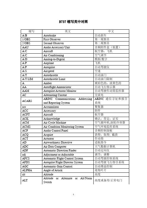
缩写
英文
中文
config
Configuration
形态;构型
CONT
Continued
继续的
COS
Cosine
余弦
CP
Control Panel
控制面板
CPROS
Crew Position
机组位置
CPS
Cycles Per Second
循环/秒
CPU
Central Processing Unit
Altitude
高度
ALT
Altitude or Alternate or Alt/Norm Switch
高度或备用/正常电门
缩写
英文
中文
altm
Altimeter
高度表
AM
Amplitude Modulation
调幅
amb
Ambient
环境;周围
amp
Ampere(s)
安培
AMP
Amplifier
Battery
电池;电瓶
BBL
Body Buttock Line
机身纵剖线
BCD
Binary Coded Decimal
二进制编码的十进制
BCF
Bromo ChlorodiFluoromethane (Halon)
卤素灭火剂
BFE
Buyer Furnished Equipment
买方供应设备
缩写
英文
断开
DISCH
Discharge
断开;释放
DLA
Delay
延迟;滞后;延时
DLK
Downlink
飞机用语英文及缩写

飞机用语英文及缩写缩写 ABBREVIATION LISTAA/C air conditioning 空气调节A/G air/groundA/L autoland 自动落地A/P autopilot 自动驾驶A/S airspeed 空速A/T autothrottle自动油门, adjustment/test 调整/测试ABNORM abnormal 不正常的AC alternating current 【电】交流电ACARS ARINC Communications Addressing and Reporting SystemACCEL acceleration, accelerate 使增速ACM air cycle machine 空气循环机ADC air data computer 大气资料电脑ADF automatic direction finder 自动方位寻找器ADI attitude director indicator 姿态指示器ADP air driven pump, air driven hydraulic pump 气动液压泵ADV advance 推进AFCS automatic flight control system 飞控系统AGL above ground level 地标位AI anti-ice 防冰AIDS aircraft integrated data system 整合资料系统AIL aileron 副翼ALT altitude 高度ALTM altimeter 高度计ALTN alternate 交替的ALTNT alternate 交替的AMB ambient 环绕的AMM Airplane Maintenance Manual 修护手册ANN announcement 通告ANNUNC annunciator 通告器ANT antenna 天线AOA angle of attack 功角APB auxiliary power breaker 辅助的动力断电器APD approach progress display 接近行进显示APL airplane 飞机APPR approach 接近APPROX approximately 近乎APU auxiliary power unit 辅助的动力单元ARINC Aeronautical航空学的Radio Incorporated【美】有限责任的ARINC IO ARINC I/O errorARNC STP ARINC I/O UART data strip error 通用非同步收发传输器ASA autoland status annunciator 自动落地状况通告器ASP audio selector panel 音频选择面板ASYM asymmetrical 非对称的ATC air traffic control 空中交通管制ATC/DABS air traffic control/discrete address beacon system ATT attitude 姿态ATTND attendant 服务员AUTO automatic 自动装置的AUX auxiliary 辅助的AVM airborne vibration monitor 空中震动监视器BB/CRS back course 回程BARO barometric 气压计的BAT battery 电池;蓄电池BFO beat扑动frequency oscillator 频率振汤器BITE built-in test equipment 装备自我测试BK brake 煞住(车)BKGRD background (干扰录音或无线电广播的)杂音BPCU bus power control unit 汇流排电力控制单元BRKR breaker 断电器BRT bright 发亮的BTB bus tie束缚breaker 汇流排联系断电器BTL bottle 瓶子CC/B circuit breaker 【电】断路器,断路开关C center 中央CADC central air data computer 中央大气资料电脑CAPT captain (飞机的)机长CB circuit breaker 【电】断路器,断路开关CCA central control actuator 中央控制致动器CCW counterclockwise 逆时针方向的CDU control display unit 控制显示器CH channel 频道CHAN channel 频道CHG change 改变CHR chronograph 记时器CHRGR charger 充电器CK check 检查CKT circuit 【电】电路;回路CL close 关闭;盖上;合上CLB climb 倾斜向上CLR clear 变乾净;变清楚CLSD closed 关闭的;封闭的;闭合的CMD command 命令CMPTR computer 电脑CNX cancelled 取消,废除;中止COL column 圆柱 (报纸的)栏,段COMM communication 通讯COMP compressor 压缩机COMPT compartment 隔间CON continuous 连续的,不断的COND condition 状态CONFG configuration 结构;表面配置CONFIG configuration 结构CONN connection 连接CONT control 控制CP control panel 控制面板CPCS cabin pressure control system 舱压控制系统CPS cycles per second 每秒循环CRS course 方向CRT cathode阴极ray射线 tube 阴极射线管CRZ cruise 巡航CSEU control system electronics unit 控制系统电子元件CT current电流transFORMer变压器CTN caution 注意CTR center 中央CU control unit 控制元件CUST customer 顾客;买主CW clockwise 顺时针方向的CWS control wheel steering掌舵DDA drift漂移angleDADC digital air data computer 数位化大气资料电脑DC direct直系的,指挥currentDEC decrease减少, decrement减少率DECEL decelerate 降低速度DECR decrease 减少DEG degree 度数DEPR depressurize 洩压; 压下DEPT departure 离开;出发DEST destination 目标, 目的地DET detector 探测器DETNT detent (机械上的)止动装置;棘爪DEV deviation 误差;偏航DFDR digital flight data recorderDG directional方向的gyro回转仪罗盘DH decision决定height高度,海拔DIFF differential 依差别而定的;鉴别性的DIR direct 指挥DISC disconnect 使分离,分开,断开DISCH discharge 释放,排出(液体,气体等)DISCONT discontinued 停止,中断DISENG disengage 解开,解除;使脱离DISP dispatch 派遣DIST distance 距离;路程DK deck (船的) 舱面,甲板DME distance measuring equipment 测距仪DMU data management unit 资料管理单元DN down 向下DPCT differential protection current transFORMer【电】变压器DR door 门DSCRT IO discrete分离I/O errorDSPLY display 显示DSPY display 显示EEADI electronic attitude director indicator 数位化姿态指示器ECON economy 节约, 经济ECS environmental control system 环控系统EDP engine driven pump, engine hydraulic pump 引擎液压泵EEC electronic engine control 引擎电控EFDARS expanded flight data acquisition and reporting systemEFI electronic flight instruments 电子化飞行仪表EFIS electronic flight instrument systemEGT exhaust gas temperature 排气尾温EHSI electronic horizontal situation indicator 水平状况方位指示器EICAS engine indicating and crew alerting system引擎状况警告指示ELEC electrical 与电有关的,电气科学的ELEV elevation 高度;海拔EMER emergency 紧急情况ENG engage啮合,接合, engineENT entrance入口,门口, entryENTMT entertainment 娱乐EPC external power contactor 外电源接触器EPR engine pressure ratio 推力比EPRL engine pressure ratio limit 推力比范围EQUIP equipment 装备ERR error 错误ESS essential必需品EVAC evacuation 撤空;排泄物EVBC engine vane and bleed control 引擎放气控制EXH exhaust 排出;排气EXT external 外部的EXTIN extinguish, extinguished 灭火器EXTING extinguishing 熄灭FF/D flight director 飞行引向器F/F fuel flow 燃油流量F/O first officerFAA Federal美国联邦 Aviation Administration行政机构FCC flight control computer 飞行控制电脑FCEU flight controls electronic unit 飞控电子单元FCU fuel control unit 燃油控制器FDR feeder 餵食器FIM Fault Isolation Manual 故障隔离手册FL flow 流量FL/CH flight level changeFLD field(飞机)场,;(广阔的一大片)地(知识)领域;专业;(活动)范畴FLT flight (飞机的)班次FLUOR fluorescent 发亮的FMC flight management computer 飞行管理电脑FMS flight management system 飞行管理系统FREQ frequency 频率FRM Fault Reporting Manual 错误报告手册FSEU flap/slat electronic unit 副翼电控单元FT feet复, foot单英尺FWD forward 前面的GG/S glide slope, ground slope 下滑坡度GA go-around 重飞GB generator breaker 发电机断电器GCB generator circuit breaker 发电机断路器GCR generator control relay 发电机控制继电器GCU generator control unit 发电机控制组件GEN generator 发电机GHR ground handling relay 地面操作继电器GND ground 地面GP group 团体GPWS ground proximity warning system 地面接近警告GR gear 齿轮;传动装置; (飞机的)起落架GRD ground 地面GS ground speed 地速GSSR ground service select relay 地面勤务选择继电器GSTR ground service transfer relay 地面勤务转换继电器GW gross总量weight 总重HH/L high/low 高/低HDG heading 【航】航向HF high frequency 高频HORIZ horizontal 水平HP high pressure 高压HSI horizontal situation indicator 水平状况方位指示器HTR heater 加热器HYD hydraulic 液压的IIAS indicated airspeed 指示空速IDENT identification 识别;鉴定IDG integrated drive generatorIGN ignition 点火,发火;点火开关ILLUM illuminate, illuminated 被照明的;发光的ILS instrument landing system 仪降IMP imperial (度量衡)英制的IN in, input 输入INBD inboard 内侧的INC incorporated结合的, increase增大, increment增加INCR increase 增加IND indicator 指示器INFC interface 分界面INFLT inflight 飞行过程中的INHIB inhibit 抑制禁止INIT initiation 入门;开始实施INOP inoperative 不活动的INPH interphone 对讲机INST instrument 仪器;仪表INT interphone 对讲机INTLK interlock 连结INTPH interphone 对讲机INTMT intermittent 时断时续的;周期性的IP intermediate pressure 中间的压力IRS inertial reference system 惯性参考系统IRU inertial惯性的reference unit 惯性参考组件ISLN isolation 隔离ISOL isolation 隔离IVSI instantaneous瞬时的vertical speed indicator 垂直速度指示器MMCDP maintenance control display panel 修护控制显示面板MCP mode control panel 模式控制面板MCU modular模件concept观念 unitMDA minimum decision altitude 最小判断高度MIC microphone 扩音器;麦克风MIN minimum 最小量,最小数;最低限度MM Maintenance Manual 修护手册MOD module 组件;单元MON monitor 监视器;监控器MOT motion (机械的)装置,运转MPU magnetic pickup 检波器MSG message 信息MSTR master 主要的;总的MSU mode selector unit 模式选择组件MTG miles to go 英里MU management unit 管理组件MUX multiplexer 多路传输NN/A not applicable 可应用的NAC nacelle 引擎舱;气球吊篮NAV navigation 导航NCD no computed data 无法计算资料NEG negative 否定的; 反面的【电】负的,阴极的【数】负的NEUT neutral 中立的NLG nose landing gear 鼻轮起落架NO. number 数,数字NORM normal 正常的,正规的,标准的NRM normal 正常的,正规的,标准的NVMEM RD non-volatile memory read error 故障读错误排除才能消除NVMEM WR non-volatile memory write error 故障写错误排除才能消除O02 oxygen 氧气OBS observer 观察员OK okay 对,很好地OPR operate 运转OPT option 选择权OPRN operation 操作OUT output 输出OUTBD outboard 外部的OVHD overhead 头顶(船舱)顶板OVHT overheat 过热OVRD override 权力高於;优先於; 越过OXY oxygen 氧气PP/RST press to reset 压下清除故障P/S pitot皮托管(流速计);皮托静压管/static 静态的PA passenger address 客舱广播PASS passenger 旅客PCA power control actuator 电控致动器PCT percentage 百分比PDI pictorial deviation indicator 偏航图表示PES passenger entertainment娱乐system PLA power level anglePLT pilot (飞机等的)驾驶员,飞行员PMG permananet magnet generator 永磁发电机PNEU pneumatic 气动PNL panel 【电】配电盘;控电板POR point of regulation调节POS position, positive (电池的)阳极【数】正的PPOS present当前的出席的 positionPRESS pressure 压力PRG FLOW program flow error 流量程序错误PRIM primary 首要的,主要的PROC procedure 程序;手续;步骤PROG MEM ROM memory error 唯读记忆体错误PROJ projector 投射器PROT protection 保护,防护;PS pitot static 皮托管(流速计);皮托静压管PSI pounds per square inch 每平方寸上的压力磅数PSS passenger service system 客服系统PSU passenger service unit 客服组件PTT push to talk 发话PTU power transfer unit 动力传送组件PWR power 动力QQAD quick-attach-detach 快拆卸;使分离QTS quarts 一夸脱的容器QTY quantity 数量RR/T rate of turn 回转速率R/W MEM RAM memory error 随机存取记忆体错误R right 右边的RA radio altimeter, radio altitude 雷达高度RAT ram air turbine 冲压驱动RCVR reciever 接受RDMI radio distance magnetic indicator 磁场距离指示REC recorder 记录器RECIRC recirculate 再循环REF reference 参考REFRIG refrigeration 冷冻REG regulator 调节器REL release 释放,解放REP representative 代表性的,典型的REQ required 必须的RES reserve 储备RESSTART power interrupt restart error 动力中断重新起动错误REV reverse 倒退,使倒转RF right front 右前RH right hand 右手RLSE release 释放,解放RLY relay 【电】继电器RLY/SW relay/switchRMI radio magnetic indicator 磁场方位指示RMT OUT high-speed ARINC output error 汇流排输出错误RN right noseROT rotation 旋转RPM revolutions循环,(一)周期回转,旋转per minuteRPTG reporting 报导RR right rear 後方RST reset 重新设定RTO rejected丢弃takeoff起飞RUD rudder (飞机的)方向舵RW right wing 右翼RWY runway (机场的)跑道SSAM stabilizer trim/elevator asymmetry limit module尾舵飞操组件SAT static air temperature 静压空气温度SEC second 第二次SEI standby engine indicator 紧急直接引擎指示SEL select 选择SELCAL selective calling 飞航呼叫SERV service 服务SG signal generator 信号产生器SLCTD selected 选择SLCTR selector 选择器SOV shut off valve 关断阀SP speed 速度SPD speed 速度SPD BK speed brake 速煞SQL squelch 压扁SSB single side bandSTA station 驻地(各种机构的)站,所, STAB stabilizer 安定装置;安定翼STBY standby 备用STS system status 系统状况SURF surface 表面SW switch 开关SWITCH IN switch input errorSYNC synchronous 同步的SYS system 系统SYST system 系统TT/R thrust reverser 反推力器T.O. takeoff 起飞TACH tachometer 转速计TAI thermal热的anti-iceTAS true airspeed 真空速TAT total air temperature 总温TCC turbine case cooling 涡轮(机)冷却TE trailing edge 後缘(飞机的)襟翼,阻力板TEMP temperature 温度,气温TFR transfer 转换THR thrust 推力THROT throttle 节流阀THRSH threshold 门槛THRT thrust 推力THRU through 穿过;通过遍及,在...各处;在...之间,在...之中TIE bus tie系,拴,捆,扎汇流排联系TLA thrust lever angle 推力杆角度TMC thrust management computer 推力管理电脑TMS thrust management system 推力管理系统TMSP thrust mode select panel 推力选择面板TO TO/takeoff 起飞TOL tolerance 【机】公差,容限TR transFORMer【电】变压器 rectifier【电】整流器TRP thrust rating panel 推力等级面板TUNE tuner (频率))调整器;【无】调谐器TURB turbine 涡轮(机)TURBL turbulent, turbulence【气】湍流;(气体等的)紊流UUBR utility有多种用途的;通用的bus relay 汇流排继电器UPR upperUSB upper side band 【机】传送带 (无线电的)波段,频带VV/NAV vertical navigation 【经】纵向联合的导航V/S vertical speed 垂直的速率VERT vertical 垂直的VERT SPD vertical speed 垂直的速率VFY verify 验证VG vertical gyro 垂直回转仪罗盘VHF very high frequency 超高频无线电VIB vibration 震动VLD valid 合法的;有效的VLV valve 【机】阀,活门VOL volume 量;额VOLT voltage 电压;伏特数VOR VHF omni range receiver 方向无线识标VOX voice 声音VTR video tape reproducer (录音,录影的)播放装置WW/D wiring线路diagram图解W/W wheel well 轮舱WARN warning 警告;警报WG wing 机翼WHL wheel 轮子 ; 变换方向WHLS wheels 车轮WPT waypoint 位子点WSHLD windshield 挡风玻璃WX weather 天气WXR weather 气象雷达XX-CH cross channel 交叉频道X-CHAN cross channel 交叉频道XDCR transducer 变换器XMISSION transmission 传送XMIT transmit 发射XMTR transmitter 发射机XPNDR transponder 询答机YY/D yaw damper 阻尼器。
A320_AFM_飞行手册中文版_南航

第一部概述1.01.00有效页面1.02.00批准页1.03.00修订总结1.04.00型号清单1.05.00一般资料飞行手册介绍注-注意-警告的定义缩写词单位换算表1.06.00三视图A320-232飞行手册修订总结A320-232飞行手册修订总结A320-232飞行手册修订总结以下页面列出了A319/A320/A321飞行手册中所包括的全部改装。
这些内容只作为信息参考,并不能反映任何机队的情况。
飞行手册简介:本飞行手册是英文版的参考文献。
它并不可完全地作为操作依据直接应用于机组飞行。
可用于飞行的飞行机组文件必须包含有国际上所要求有相应内容和正确语句的操作手册。
在飞行手册的开头页面上已表明本飞行手册是介绍特定飞机的标准型号。
它是被法国民航局所核准的。
说明这本客户化的飞行手册是从非客户化的飞行手册的范畴内摘录的,而且是一本已被认可的介绍某一特定飞机(特定构形的飞机)或某一营运者/客户机队的文献。
它是被法国民航局支持批准的并且符合联合适航局或美国联邦航空管理局的要求。
-这本覆盖了某一特定飞机的飞行手册,可从1.01.01节上有效页面清单每页底部的生产序号所识别。
本飞行手册仅在新飞机交货时出版。
在任一飞机上的有效页面清单是不会被更新的。
飞行手册必须依据营运者/客户机队的有效页面清单来更新。
-营运者/客户机队的飞行手册可被其在有效页面清单上二或三位的代码所识别。
除此之外,在有效页面清单上所提明的每页是单独有效于其生产序号的。
概述空客公司在交货时将提供一本反映飞机构形的手册,而且必要的反映构形的改动应由空客公司批准修订。
因没有空客服务通告的第三方修订和/或如果用户没有继续被告知应用空客服务通告,空客公司将不提供修订本,而且将不担负由飞行手册带来任何后果的责任。
当交货飞机构形有明显变动时,营运者/客户应尽快通知空客公司,这样空客公司可向其提供飞行手册的修订本/更新资料。
手册的编排方式飞行手册包括:-与批准型号有关的首页-批准页包含修订号,适航当局签字和修订批准日期。
flb、tlb、clb中英文填本学习材料

第一部分航线填本常用语句范例……检查发现/报告故障……1. 航后:检查发现左后航行灯不亮。
AFTER FLIGHT(AF ):FIND L AFT POSITION LIGHT IS NOT ON.2. 检查发现右前轮磨损超标。
Check R tire of the nose landing gear is worn out of limits.3. 检查发现2号ATC故障。
Check ATC system No.2 ATC fails.4. 检查发现左外刹车组件磨损超标。
Check L outboard wear indicator pin of MLG brake assy is out of limits.航后检查发现:(AF Check)AF Check :Check L outboard wear indicator pin of MLG brake assy is out of limits. Accom plish Task Card:TZ-AF-03,check L outboard wear indicator pin of MLG brake assy is out of limits.过站检查发现:(T R check)TR check : Check L outboard wear indicator pin of MLG brake assy is out of limits. Accom plish Task:TZ-TR-00,Check L outboard wear indicator pin of MLG brake assy is out of limits.5. 检查发现左主起落架一液压管漏油超标。
Check the L MLG hydraulic tube leakage is out of limits.6. 检查发现13B座位小桌板不能收起,无法保持在收上位。
F16飞行员培训手册2
BY ORDER OF THE SECRETARY OF THE AIR FORCE AIR FORCE INSTRUCTION 11-2F-16VOLUME 220 JUNE 2006Flying OperationsF-16--AIRCREW EVALUATION CRITERIACOMPLIANCE WITH THIS PUBLICATION IS MANDATORY ACCESSIBILITY: Publications and forms are available on the e-Publishing website at for downloading or ordering.RELEASABILITY: There are no releasability restrictions on this publication.OPR:HQ ACC/A3TV Certified by:HQ USAF/ A3O(Brig Gen Robert C. Kane) Supersedes AFI 11-2F-16, V olume 2,15 March 2001Pages:64This volume implements AFPD 11-2, Aircraft Rules and Procedures; AFPD 11-4, Aviation Service; and AFI 11-202V2, Aircrew Standardization/Evaluation Program. It applies to all F-16 units. This instruction does apply to Air National Guard (ANG) and Air Force Reserve Command (AFRC). MAJCOMs/DRUs/ FOAs are to forward proposed MAJCOM/DRU/FOA-level supplements to this volume to HQ USAF/ A3OT, through HQ ACC/A3TV, for approval prior to publication in accordance with (IAW) AFPD 11-2, paragraph 4.2. Copies of MAJCOM/DRU/FOA-level supplements, after approved and published, will be provided by the issuing MAJCOM/DRU/FOA to HQ USAF/A3OT, HQ ACC/A3TV, and the user MAJ-COM/DRU/FOA and National Guard Bureau offices of primary responsibility. Field units below MAJ-COM/DRU/FOA level will forward copies of their supplements to this publication to their parent MAJCOM/DRU/FOA office of primary responsibility for post publication review. NOTE: The terms Direct Reporting Unit (DRU) and Field Operating Agency (FOA) as used in this paragraph refer only to those DRUs/FOAs that report directly to HQ USAF. Keep supplements current by complying with AFI 33-360V1, Air Force Content Management Program—Publications. See paragraph 1.2. of this volume for guidance on submitting comments and suggesting improvements to this publication.This publication requires the collection and or maintenance of information protected by the Privacy Act (PA) of 1974. The authorities to collect and or maintain the records prescribed in this publication are Title 10, United States Code, Chapter 857 and Executive Order 9397, Numbering System for Federal Accounts Relating to Individual Persons, November 22, 1943. Forms affected by the PA have an appropriate PA statement. System of records notice F011 AF XO A, Aviation Resource Management System (ARMS) (December 26, 2002, 67 FR 78777) applies. Paperwork Reduction Act of 1974 as amended in 1996 affects this instruction. Ensure that all records created as a result of processes prescribed in this publica-tion are maintained in accordance with AFMAN 37-123 (will convert to 33-363), Management of Records and disposed of in accordance with the Air Force Records Disposition Schedule (RDS) located at https:// .Recommendations for improvements to this volume will be submitted on AF IMT 847, Recommenda-tion for Change of Publication, through channels, to the parent MAJCOM Stan/Eval. Parent MAJCOM Stan/Eval will forward approved recommendations to lead command OPR (HQ ACC/A3TV, 204 Dodd Blvd, Suite 133, Langley AFB VA 23665-2789). HQ USAF/A3 is the approval authority for interim changes to this instruction.SUMMARY OF CHANGESThe opening paragraph to this instruction has been reworded for clarity and updated. AF Form 8 has been changed to AF IMT 8, Certificate of Aircrew Qualification throughout the document Para 1.2.: Recom-mendation for Change of Publication moved to opening paragraph. Para 1.3.1.: added reference to new Chapter 4 for emergency procedure evaluations. Para 1.3.2.: added “video tape recorder” and Air Com-bat Maneuvering Instrumentation“, deleted corresponding abbreviation (all abbreviations of terms which show up just one time have been deleted in the document). Para 1.3.5.: deleted (merged into para 2.1.2.), following paragraph renumbered. Para 1.4.2.: added term “angle of attack”. Table 1.1.: new layout, added grading criteria. Para 1.5.: reworded for clarity. Para 1.5.1.1. to 1.5.1.4.(and sub-paragraphs): rearranged, reworded for clarity. Added explanation for “XX”. Added requirement for Engine Failure/Airstart and Out Of Control Recovery CAPs for all EPEs. Para 1.5.2. and 1.5.2.1.: reworded for clarity. Para 1.5.2.3.: deleted; “Recovery Procedures” now incorporated in para 1.5.1.1.3. Para 1.5.3.: reworded. 1.5.3.3.: added “threat reaction”. Para 1.5.3.5.: added term “terrain following radar”. Para 1.5.4.: reworded for clarity. Para 1.5.5.: added paragraph on combined MSN/INSTM/QUAL EPEs. Para 1.5.6.: renumbered. Para 1.6.: renumbered; paragraph on publications moved to 2.1.3.. Para 1.6.1.: reworded, added MAJCOM Ready Aircrew Program tasking message events as reference. Para 1.6.2.: added term “Forward Air Con-troller”. Para 1.6.3.: added sentence about shot validity. Table 1.2.: updated to match corresponding text and actual requirements. Para 1.6.4.: text added for clarification. Para 1.8.: deleted text on record disposi-tion. Para. 2.1.1.: deleted sentence on applicability (already covered in foreword). Para 2.1.2. to 2.1.2.3.: text reworded and added to reflect more differentiated evaluation requirements. Para 2.1.3.: former para-graph 1.6. Deleted explanation for “XX”; added procedures for ANG. Para 2.1.3.1.: added. Para 2.1.3.5.: added. Para 2.1.4.: text amended – aspects of Cockpit/Crew Resource Management are now embedded in other grading criteria. NOTE deleted. Para 2.1.5.: added paragraph on combined MSN/INSTM/QUAL evaluations. Para 2.2.: text added, deleted requirement for approval to administer an INSTM/QUAL eval-uation on a compatible training mission. Para 2.2.1. to 2.2.1.4.: renumbered, “Instrument Refresher Course” deleted. Para 2.3.: deleted requirement for written mission evaluation profiles; paragraph reworded for clarity; evaluations during exercises or exercise deployments are encouraged now. NOTE on BMC-aircrew added. Para 2.3.2.: reworded. Para 2.3.2.1.: deleted. Para 2.3.2.2.: deleted. Para 2.3.3.: added AFTTP 3-1 as reference. Para 2.3.3.3.: reworded for clarity. Para 2.3.5.: added “(A)”. 2.3.6.: text on FTU Instructor Pilots relocated in para 2.5.: following paragraphs renumbered. Para 2.3.6.: Reworded to make RESCORT mandatory. Para 2.3.7. (old): deleted. Para 2.4.: added reference Chapter 4 Para 2.5. and following sub-paragraphs: reworded for clarity; text supplemented to better describe Instructor eval-uation requirements. Para 2.6.1.2.: reworded. Para 2.6.2.: deleted term “Emergency Procedure Evalua-tion”. Table 2.1.: newly formatted, completely revised. Deleted SEAD as mission evaluation profile. Several grading areas have been reevaluated as mandatory items on specific mission profiles. NOTE 1.: amended and reworded for clarity. NOTE 3.: added “Simulated Flame Out”; amended to give more pre-cise guidance on SFO requirements. Added PACAF to the exception. NOTE 4.: reworded. NOTE 7.: added. NOTE 8.: added. Table 2.2.: added criteria for EPE. Para 3.2.1.1.1. to 3.2.1.1.3.: text added to bet-ter reflect all relevant aspects of mission planning and crew coordination. Para 3.2.1.2. and sub-para-graphs: criteria for publications added. Para 3.2.2.1.1. to 3.2.2.1.3.: text added. Para 3.2.2.2.1. to 3.2.2.2.3.: text added and amended. Para 3.2.2.3.1. to 3.2.2.3.3.: text added and amended. Para 3.2.2.4.1. and 3.2.2.4.2.: reworded. Para 3.2.4.2.and 3.2.4.3.: reworded. Para 3.2.5.1.3.: reworded. Para 3.2.6.1.: added term “Visual Flight Rules”. Para 3.2.6.2. and sub-paragraphs: replaced “rendezvous” with “rejoin”. Para 3.2.8.1.: deleted examples for “assigned airspace”. Para 3.2.9.1.1. to 3.2.9.1.3.: text added. Para 3.2.9.2.1. to 3.2.9.2.3.: text amended/added. Para 3.2.10.3.: text added for clarification. Para 3.2.11.1.: reworded. Para 3.2.11.3.: text added. Para 3.2.12. and para 3.2.12.1.: deleted “SIF”. Para 3.2.13.: deleted (publication check is now in para 3.2.1.2.). Para 3.2.14.: deleted terms “Advanced Handling/Tactical Maneuvering”. Para 3.2.16.: added term “Built In Test”. Para 3.2.17.1.1.: added term “Emission Control”. Para 3.2.17.2.2.: deleted last sentence. Para 3.2.17.2.3.: reworded. Para 3.2.20.: deleted “trail”. Para 3.2.20.1. to 3.2.20.3.: replaced “approach” with “recovery”. Para 3.2.22.1.: reworded. Para 3.2.22.2.1. and 3.2.22.2.2.: deleted, text included in para 3.2.22.2. Para 3.2.25.: text added to emphasis applicability of the listed criteria for VFR-approaches. Para 3.2.27.1. to 3.2.27.3.: text added to allow for aspects of Cock-pit/Crew Resource Management. Para 3.2.28.1. to 3.2.28.3.: text added to allow for aspects of Cockpit/ Crew Resource Management. Para 3.2.29.2.1.to 3.2.29.2.3.: deleted term “Critical Action Procedure”. Para 3.2.30.: added “Situational Awareness”. Para 3.2.30.1. to 3.2.30.2.: text added to reflect aspects of situational awareness. Para 3.2.31.2.: added “aircraft flight path”. Para 3.2.32.1. and 3.2.32.2.: reworded. Para 3.2.33.: text added to match para 2.5.3. Para 3.2.33.1.1. to 3.2.33.1.3.: text added to allow for aspects of Cockpit/Crew Resource Management. Para 3.2.33.2. text on chase requirements deleted 2.5.3. Para 3.2.34. and sub-paragraphs: deleted “Cockpit/Crew Resource Management”. Para 3.2.35.: corrected typo-graphical error. Para 3.2.35.1.: text added to describe “Q” criteria. Para 3.2.36. and sub-paragraphs: added item “Task Prioritization” and corresponding criteria. Para 3.3.1.1. to 3.3.1.2.: added “leg timing” as parameter. Para 3.3.2.. to 3.3.2.3.: added “enroute descent”. Para 3.3.4.1.: added terms ”Minimum Descent Altitude”, “Visual Descent Point”, “Missed Approach Point”. Para 3.3.5.: split criteria for PAR and ILS-approaches into 2 areas. Para 3.3.5. and sub-paragraphs: PAR only. Para 3.3.6. and sub-para-graphs: added text on ILS-approaches. Para 3.4.1.1.1.: reworded. Para 3.4.1.2.2.: changed “poor” to “low”. Para 3.4.1.3.: reworded, deleted “GCI” and “AWACS”. Para 3.4.1.5. and sub-paragraphs: changed “Radar lookout” to “Radar Mechanization” or “Radar search”. Para 3.4.1.6.1. and 3.4.1.6.3.: text added. Para 3.4.1.7.2.: High altitude and Medium Altitude grading criteria merged. Para 3.4.1.7.3. and sub-para-graphs: renumbered, reworded. Para 3.4.1.8.1. to 3.4.1.8.3.: added term “evasive maneuvers”. Para 3.4.1.11.: text added. Para 3.4.1.11.2.1.: added PET shot parameter. Para 3.4.1.12.: added term “Rules of Engagement”. Para 3.4.1.14.: deleted term “Terrain Following Radar”. Para 3.4.1.15.: added “not applica-ble for FTU”. Para 3.4.1.16. and sub-paragraphs: reworded for clarity. Para 3.4.1.18.and sub-paragraphs: added area “Sensor management”. Para 3.4.1.19.: added. Para 3.4.2.1.: changed “Radar Search” to “Radar Mechanization”. Para 3.4.2.3.: added “Combat Air” and “(CAP)”. 3.4.2.3.1. to 3.4.2.3.3.: reworded for clarity. Para 3.4.2.5.1.: reworded/text added to better cover all aspects of offensive maneuvering. Para 3.4.2.5.2.: reworded. Para 3.4.2.6.1.: text added. Para 3.4.2.7.1. to 3.4.2.7.3.: reworded for clarity. Para 3.4.2.8. and sub-paragraphs: added area “Air-to-Air Systems Employment”. Para 3.4.2.9.: added area “Command and Control Integration”. Para 3.4.3.1.1. and 3.4.3.1.2.: added “with radar and/or TGT IR and/ or visual acquisition”. Para 3.4.3.2., NOTE 3 and NOTE 4.: text added. Para 3.4.3.2.2.1. to 3.4.3.2.2.3.: examples for single event weapon scores deleted. Para 3.4.3.2.3.1. to 3.4.3.2.3.3.: tables newly formatted. Para 3.4.3.4.: and sub-paragraphs: text added. Para 3.4.3.5. and sub-paragraphs: criteria for Precision Guided Munitions Delivery Procedures added. Para 3.4.3.7. and sub-paragraphs: criteria for System Weapons Delivery Procedures (GPS Aided Weapons) added. Para 3.4.3.8. and sub-paragraphs: criteria for System Weapons Delivery Procedures (General Purpose Munitions) added. Para 3.4.3.9. and sub-para-graphs: criteria for Close Air Support/Time Sensitive Targeting added. Para 3.4.3.10.: added. Para 3.4.4.:added term “Destruction of Enemy Air Defenses”. NOTE added. Para 3.4.4.1.1.: reworded for clarity. Para 3.4.4.1.2.: deleted text. Para 3.4.4.1.3.: reworded. Para 3.4.5.2. and sub-paragraphs: changed “Photo Quality” to “Imagery Quality”; combined former areas 112 “Photo Quality” and 113 “EEI” into one area. Para 3.4.5.3.: deleted area “EEI”, added administrative text. Para 3.4.5.4.: deleted. Para 3.4.6.3.1.: changed “fighters” to read “strikers”. Para 3.4.6.4.1. to 3.4.6.4.3.: changed “fighters” to “strikers”. Para 3.4.6.5.: added text “(Type 1 control only)”. Para 3.4.6.5.1. to 3.4.6.5.3.: reworded for clarity. Para 3.4.6.6.1.: changed “fighters” to “strikers”. Para 3.4.6.6.2.: changed “fighters” to “strikers”, added text. Para 3.4.6.7.1.: changed “fighters” to “strikers”. Chapter 4 added to specify grading criteria for Emer-gency Procedures Evaluations. Para 4.3. and 4.4.: added to comply with administrative requirements. Attachment 1 references, abbreviations and acronyms updated to match corresponding text of the instruction.A bar ( | ) indicates revisions from the previous edition.Chapter 1— GENERAL INFORMATION 61.1.General (6)1.2.Waivers (6)1.3.Procedures (6)1.4.Grading Instructions (6)Table 1.1.General Criteria. (7)1.5.Emergency Procedures Evaluation (7)1.6.Documentation of Weapons Employment Results (9)Table 1.2.Weapons Employment Scores. (10)Chapter 2— EVALUATION REQUIREMENTS 112.1.General (11)2.2.Instrument/Qualification Evaluation (12)2.3.Mission Evaluation (12)2.4.Formal Course Evaluation (13)2.5.Instructor Evaluation (13)2.6.Instructor Pilot Rear Cockpit Landing Evaluations (14)Table 2.1.FLIGHT Evaluations. (15)Table 2.2.Emergency Procedure Evaluations (21)Chapter 3— FLIGHT EVALUATION CRITERIA 263.1.General Grading Standards (26)3.2.General (26)3.3.Instrument (39)3.4.Tactical Employment (42)Chapter 4— EMERGENCY PROCEDURES EVALUATION CRITERIA 574.1.General Grading Standards: (57)4.2.General: (57)4.3.Forms Prescribed (60)4.4.Forms Adopted (60)Attachment 1— GLOSSARY OF REFERENCES AND SUPPORTING INFORMATION 61Chapter 1GENERAL INFORMATION1.1. General.All evaluations will be conducted IAW the provisions of AFI 11-202V2 and this volume.1.2. Waivers.Waiver authority for this publication is the MAJCOM DO/A3. Waivers will be requested from the parent MAJCOM Stan/Eval through appropriate channels.1.3. Procedures.1.3.1. Flight examiners (FEs) will use the evaluation criteria contained in Chapter 3for conductingflight evaluations and Chapter 4 for emergency procedure evaluations (EPE). To ensure standard and objective evaluations, flight examiners will be thoroughly familiar with the prescribed evaluation cri-teria.1.3.2. Recording devices (video tape recorders (VTR), air combat maneuvering instrumentation, etc.)should be used, when available, to reconstruct/evaluate the mission.1.3.3. Unless specified, the examinee or FE may fly in any flight position/seat (to include chase)which will best enable the FE to conduct a thorough evaluation.1.3.4. The FE will brief the examinee on the purpose of the evaluation and how it will be conductedprior to flight. The examinee will accomplish required flight planning in accordance with the flight position during the evaluation. Higher Headquarters FEs (and unit FEs as determined locally) may assist in mission planning/briefing as tasked and will be furnished a copy of necessary mission data, mission materials, and data transfer cartridge loads.1.3.5. The FE will thoroughly debrief all aspects of the evaluation. This debrief will include theexaminee's overall rating, specific deviations, area grades assigned (if other than qualified) and any required additional training.1.4. Grading Instructions.Standards and performance parameters are contained in AFI 11-202V2 and this instruction.1.4.1. The FE will base tolerances for in-flight parameters on conditions of smooth air and a stableaircraft. Do not consider momentary deviations from tolerances, provided the examinee applies prompt corrective action and such deviations do not jeopardize flying safety. The FE will consider cumulative deviations when determining the overall grade.1.4.2. When grading criteria specify that airspeed/angle of attack (AOA) be evaluated and the flightmanual lists only a minimum/maximum/recommended airspeed/AOA for that area, the examinee will brief the desired airspeed/AOA.1.4.3. The FE will compare examinee performance for each area accomplished during the evaluationwith the standards provided in this volume and assign an appropriate grade for the area. Derive theoverall flight evaluation grade from the area grades based on a composite for the observed events and tasks IAW this instruction.1.4.3.1. FEs will use the grading criteria in this volume to determine individual area grades. FE judgment must be exercised when the wording of areas is subjective and when specific situations are not covered.1.4.3.2. If the examinee receives an unqualified area grade in any of the critical areas identified by this volume, an overall qualification level of "Q-3" will be assigned.1.4.3.3. FE judgment will be the determining factor in arriving at the overall grade.1.4.3.4. The following general criteria apply during all phases of flight except as noted for spe-cific events and instrument final approaches:Table 1.1. General Criteria.1.5. Emergency Procedures Evaluation.In order of preference, the EPE will be conducted in a flight simulator/unit training device (UTD), cockpit procedure trainer (CPT), or verbally. Only conduct a verbal EPE if a flight simulator/UTD or CPT is not available or not configured appropriately for the evaluation. Grading criteria for each required item are listed in Chapter 4. This evaluation will include areas commensurate with examinee's Ready Aircrew Program (RAP) training level and event qualifications.1.5.1. The following items are required on all emergency procedure evaluations:1.5.1.1. Emergency Procedures. All Critical Action Procedures (CAP) should be evaluated.1.5.1.1.1. Evaluate a minimum of two emergency procedures, one of which is a CAP, from the Ground Emergencies Section of Chapter 3 of the T.O. 1F-16XX-1 (XX denotes model - A/C/CG/CJ). Q Altitude +/- 200 feet Airspeed +/- 5% Course+/- 5 degrees/3 NM (whichever is greater) TACAN Arc+/- 2 NM Fix-to-Fix+/- 2 NM Landing150’ to 1000’ Q- Altitude+/- 300 feet Airspeed +/- 10%Course+/- 10 degrees/5 NM (whichever is greater) TACAN Arc+/- 3 NM Fix-to-Fix+/- 3 NM Landing0-149’; 1001’ to 1500’ U Exceeded Q- limits1.5.1.1.2. Evaluate a minimum of two emergency procedures, one of which is a CAP, from theTakeoff Emergencies Section of Chapter 3 of the T.O. 1F-16XX-1.1.5.1.1.3. Evaluate both the Engine Failure/Airstart and Out Of Control Recovery CAPs andan additional emergency procedure from the In-Flight Emergencies Section of Chapter 3 of the T.O. 1F-16XX-1.1.5.1.1.4. Evaluate a minimum of two emergency procedures from Landing Emergencies Sec-tion of Chapter 3 of the T.O. 1F-16XX-1.1.5.1.1.5. All CAPs will be evaluated by completion of a written CAPs sheet at the beginningof the EPE. This will complete the CAPs requisite for the evaluation. Any incorrectly com-pleted CAP will result in a “U” for the CAPs requisite. The EPE will not be started until suc-cessful completion of the CAPs requisite.1.5.1.2. Aircraft General Knowledge.1.5.1.3. Cockpit/Crew Resource Management (CRM).1.5.1.4. Unusual Attitude Recoveries. This also fulfills the Area 15 (Unusual Attitude Recoveries)requirement for Instrument/Qualification (INSTM/QUAL) evaluations.1.5.2. All INSTM/QUAL EPEs will include the following additional items:1.5.2.1. AFMAN 11-217, Instrument Flight Procedures. Evaluate a minimum of one heads-updisplay (HUD) -out approach and use of standby/emergency instruments. Emphasis should be on whether the approach would permit a safe landing.1.5.2.2. Alternate/divert airfields. Evaluate a minimum of one approach at other than home base.1.5.3. All Mission (MSN) EPEs will include the following items (tailor MSN evaluation scenarios to unit tasking/mission).1.5.3.1. Weapons system operation.1.5.3.2. Electronic attack (EA)/Electronic Protection (EP)/All Aspect Missile Defense (AAMD).1.5.3.3. Evasive action/Threat Reaction.1.5.3.4. Weapons employment and switchology.1.5.3.5. Terrain Following Radar (TFR) procedures (if applicable).1.5.4. Examinees receiving an overall unqualified grade will be placed in supervised status until rec-ommended additional training is completed and/or a reevaluation is successfully accomplished. Examinees receiving an overall unqualified grade because of an unsatisfactory CAP accomplishment will not be permitted to fly until a successful reevaluation is accomplished. For EPEs in which the examinee is qualified, but requires additional training, the FE will indicate whether the additional training will be accomplished before the next flight. Additional training and reevaluations will be accomplished IAW AFI 11-202V2.1.5.5. Normally, an EPE will be conducted separately for the pilot INSTM/QUAL and MSN evalua-tions. In situations where INSTM/QUAL and MSN evaluation eligibility zones coincide, a single EPE may be administered to fulfill the requisites for the combined MSN/INSTM/QUAL evaluations. The combined EPE must be of sufficient scope and length to ensure all required areas for each evaluation are accomplished.1.5.6. The following grading criteria will be used to grade individual items on EPEs:1.5.6.1. Q. Performance is correct. Quickly recognizes and corrects errors.1.5.6.2. Q-. Performance is safe, but indicates limited proficiency. Makes errors of omission orcommission.1.5.6.3. U. Performance is unsafe or indicates lack of knowledge or ability.1.6. Documentation of Weapons Employment Results.Weapons employment results will be documented in the Mission Description Section of the AF IMT 8 for MSN evaluations. Include entries for each type of actual and simulated ordnance that was employed.1.6.1. Air-to-Surface. Results will be recorded as Hit or Miss for each air-to-surface record delivery.Flight examiners may use either AFI 11-2F-16V1, F-16--Aircrew Training, individual weapons events or current MAJCOM Block XX RAP tasking message events (e.g. combined events, etc.) when deter-mining grading or assigning additional training. For air scored events and/or for VTR assessed deliv-eries, FEs will determine weapons employment results. Air scored and/or VTR assessed deliveries will be annotated with an asterisk (or asterisks as required). Document results as in Table 1.2. or as by PEX format.1.6.2. Forward Air Controller (FAC) Target Marks. For the purpose of FAC target mark, marks willbe scored as a Hit or a Miss by the FE in either FAC or fighter aircraft. Marks will be scored as a "Hit"if they are considered usable for marking the designated target, delivered in a timely manner and delivery used is tactically sound. They will be scored as a "Miss" if they are unusable for target mark-ing, untimely or the deliveries are tactically unsound (i.e., excessive altitude loss, unnecessary expo-sure to the threat, excessive tracking time, etc.).1.6.3. Air-to-Air. Record the number of simulated missile/gun firing attempts and the number thatwere valid as in Table 1.2.Shot validity will be evaluated at pickle with all parameters IAW AFTTP 3-1.1.1.6.4. FE Judgment. FE judgment will be the determining factor in deciding the weapons employmentgrade. If the examinee fails to qualify in any event(s), the FE may elect to award a higher area grade than warranted by the score(s). The FE will include justification for such an award in the Comments Section of the AF IMT 8. Include entries for each type of simulated ordnance that was employed.Table 1.2. Weapons Employment Scores.Weapons employment scores were: (examples)(for abbreviations and acronyms see Attachment 1)HARB HADB LALD LAT HARM LGB*Hit **Hit Hit/Miss Hit/Hit *Hit *HitATTEMPTED V ALIDA/A Gun 2 1AIM 120 2 2 *VTR /simulator/UTD assessed /**Air ScoredNOTE:Flight examiners may use either AFI 11-2F-16V1 individual weapons events or current MAJCOM Block XX RAP tasking message events (e.g. combined events,MAD, etc.) when completing Weapons Employment Scores.Chapter 2EV ALUATION REQUIREMENTS2.1. General.2.1.1. All evaluations will follow the guidelines set in AFI 11-202V2.2.1.2. Required areas for flight evaluations are shown in Table 2.1.and for EPEs in Table 2.2. Whenit is impractical or not possible to accomplish a required flight evaluation area inflight, it may be eval-uated by an alternate method (i.e., simulator/UTD, CPT, or by verbal examination) in order to com-plete the evaluation. Document the reason and type of alternate method used in the Comments portion of the AF IMT 8, Certificate of Aircrew Qualification. If the FE determines the required item cannot be adequately evaluated by an alternate method, the examinee will require an additional flight to com-plete the evaluation.2.1.2.1. Areas annotated with an "R" are required items for that evaluation.2.1.2.2. Areas annotated with an “R1” require evaluation of at least one of the items under theassociated section and category for that evaluation (e.g., for the Critical Action Procedures cate-gory under the Ground Emergencies Section listed in Table 2.2., at least one CAP is required for both the INSTM/QUAL and MSN evaluations).2.1.2.3. Areas indicated with an “R2” require evaluation of at least two of the items under theassociated section for that evaluation (e.g., for the emergency procedures under Landing Emer-gencies Section listed in Table 2.2., at least two emergency procedures are required for both the INSTM/QUAL and MSN evaluations).2.1.3. Publications Check.(N/A ANG/AFRC) Publications that will be checked are:2.1.3.1. T.O. 1F-16XX-1 (ACC/PACAF)2.1.3.2. T.O. 1F-16XX-1CL-12.1.3.3. T.O. 1F-16XX-34-1-1CL-12.1.3.4. Local In-flight Guide2.1.3.5. Any additional publications issued to aircrews and specified in the unit addendum to AFI11-202V2.ANG/AFRC: Currency of Flight Publications. Evaluate all issued checklists for currency and accuracy on all flight evaluations. Units may specify additional publications to be evaluated in the unit supplement to AFI 11-202V2.2.1.4. Cockpit/Crew Resource Management (CRM)In accordance with AFI 11-290, Cockpit/Crew Resource Management, CRM skills will be evaluated during all evaluations. CRM skills are integral to all phases of flight and are embedded within specific grading criteria. Therefore, no specific evaluation criteria area titled CRM exists. As all the CRM skills listed on the AF IMT 4031 are included/embedded, use of the IMT 4031 is unnecessary for eval-uations in the F-16. The Stan/Eval trend program can be used to measure the effectiveness of CRM training.2.1.5. With the approval of the Operations Group Commander, the INSTM/QUAL evaluation and theMSN evaluation may be combined as a single evaluation. Unit Commanders, with coordination through the unit Chief of Stan/Eval, may designate experienced pilots for this combined evaluation option. Evaluations flown in this manner must fulfill all current INSTM/QUAL and MSN evaluation requirements, including ground phase requisites. For combined MSN/INSTM/QUAL evaluations, one EPE may be accomplished that encompasses requirements of both EPEs. Additional simulator time may be required to complete these items.2.2. Instrument/Qualification Evaluation.A mission flown according to instrument flight rules (to the maximum extent practical) best fulfills the objective of the INSTM/QUAL evaluation. To the maximum extent possible, this evaluation will include approaches at airfields other than home or deployed locations (USAFE: Preferably non-US locations). Approaches may be flown to fields which have a non-published, practice approach available (e.g. Visual Flight Rules (VFR) conditions only approach), but not a published FLIP approach. The intent is to grade instrument procedures which are independent of an approach’s certification (to use a non-published approach, the approach plate must be built using the standards applied to published approach plates, local OGV must approve use of the approach, and approval for the approach to must be documented in the local unit supplement to AFI 11-202V2). This evaluation may be administered on any compatible training mis-sion. When B/D model aircraft are available, pilots may complete their INSTM/QUAL evaluation with an FE occupying the rear cockpit.2.2.1. Minimum ground phase requisites are:2.2.1.1. Instrument examination.2.2.1.2. Closed and open book qualification examinations.2.2.1.3. EPE.2.2.1.4. CAPs Written Exam. Answers must contain all critical action items in proper sequence.Abbreviations are allowed.2.3. Mission Evaluation.MSN evaluation will be flown IAW current tactics, unit tasking and theater Area of Responsibility scenar-ios and will incorporate all appropriate evaluation requirements from Table 2.1.. Scenarios that represent unit Designed Operational Capability (DOC) tasking satisfy the requirements of this evaluation. The pro-files will be designed to evaluate the training/flight position/special qualifications as well as basic airman-ship of the examinee. Initial MSN evaluations will be given in the primary DOC of the unit unless directed otherwise by the squadron commander for assigned contingency tasking. MSN evaluations will normally be flown using established tactics, techniques, and procedures, and in accordance with pub-lished unit standards. Examinees will be evaluated in the position of their highest qualification. At the FEs discretion, portions may be flown in another position, but the emphasis is to have examinees evaluated at their highest qualification level. Wingman may be required to brief (to include tactics) and/or lead certain phases of the mission, but will not be evaluated using flight lead grading criteria. Evaluations during exer-cises or exercise deployments are encouraged. Evaluations during contingency/combat deployments will be given as a last resort in order to maintain mission qualification status.NOTE:Basic Mission Capable (BMC) aircrew will only be evaluated on those missions routinely per-formed. Examinees will only be evaluated on those areas for which they are qualified.。
- 1、下载文档前请自行甄别文档内容的完整性,平台不提供额外的编辑、内容补充、找答案等附加服务。
- 2、"仅部分预览"的文档,不可在线预览部分如存在完整性等问题,可反馈申请退款(可完整预览的文档不适用该条件!)。
- 3、如文档侵犯您的权益,请联系客服反馈,我们会尽快为您处理(人工客服工作时间:9:00-18:30)。
空中加油
空中加油对于一名新飞行员来说是非常富有挑战性的任务。那意味着你必须
要与一个庞大的钢铁怪物飞的足够的贴近(当然就是加油机了),并且又不能够
碰到它要保持一定的安全距离,同时保持住300节的速度。这绝不是件简单的工
作,但它也确实是可以做到的
任务26:空中加油
在朝鲜半岛,目标距离通常都在F-16的作战半径以内,而在巴尔干的战役中会有一些
更长距离奔袭的任务,但一般也会在F-16的有效作战距离内。所以,空中加油通常情况下
都是没什么必要的。而它的功用也就在于能使你在空中停留的更长一些
#找到加油机
空中加油的理论是很容易被理解的。实际上,我敢肯定你从前面的训练任务中已经体会
到空战不是智力对抗。它的挑战性来自于实际的操作,而空中加油则最好的体现出了这一点。
空中加油中的第一步便是找到你的加油机,最简单的方法是询问AWACS最近的加油机的位
置。按Q键两次调出AWACS的第二页命令目录,然后按“4”键“Vector to tanker” AWACS
会给出tanker的距离和方位。
需要指出的是,AWACS同时会给你一个加油机的 air-to-air TACAN 频道,这个频道能
在你的HIS显示器上提供给你加油机的距离和方位。当你从预警机那里得到这个TACAN频
道后,把它输入到UFC T-ILS的显示中,选择AA-TR选项。
接下来,将导航模式转到TCN处。现在你从和AWACS的对话和你自己的HIS中都已
经能够获得tanker的方位和距离了。只要跟随这些引导驾驶不久KC-10就会出现在你的雷
达里了。当雷达里出现目标时,锁住它同时在HIS中检查其距离和方位。
顺便指出,你不一定非要用空
空TACAN。另一种方法只是不停的
询问AWACS并遵循其的引导便可
以了。例如,AWACS也许会说,
“Bearing 090, angels 19, 20 miles,
图26-1
110 Yankee.”这条语句意味着要是你转向90度的方向你的机鼻就会指向加油机了。最后的那
部分提供给你最近加油机的空空TACAN频道。图26-3显示在空空TACAN模式的HIS中
看到的目标方位。
这个训练任务在开始时会将你直接置于一架加
油机的后方很近的距离内所以你可以直接反复的尝
试练习与加油嘴的对接。任务中没有寻找KC-10加
油机的内容,但要是你真想练习的话,就飞离加油
机然后利用AWACS和TACAN回到你原来到位置去
加油。
图26-3
#接近加油机
现在是时候打开F-16背部的油嘴舱门了。你可以在左侧的master fuel 的面板上找到这
个开关
一旦你发现了加油机,窍门就在于跟随其后保持在一个绝佳的位置。加油机会在一个椭
圆的类似运动场的跑道的轨迹上飞行,所以大多数时间它们会保持水平的直线飞行状态。在
你确定预测好加油机以后一段时间的路线之后,请求加油(request fuel)。按“Y”键调出加
油机指令目录然后按“1”(Request refueling)。这样做之后,加油机会加速到300节并会保
持之前所说的那个椭圆形轨迹飞行。当你跟随加油机前进了大约1 英里之后,告诉它你准
备进行加油了(ready to refuel)。按“Y”键然后按“2”(Ready to refuel)。加油机应该会
在这时放出空中加油管(air refueling boom)(如果这之前它还没有这么做的话)当你从6
点钟方向接近加油机时控制好飞机使其千万别飞过头。记住你接近目标有多快。既然对接
(overtake)是依赖于雷达的,你就必须用雷达来锁住目标以便在HUD中得到连接过程中
的数据信息(如图26-4所示)。
图26-4
精确控制对接的一个很好的准则就是当你在距离加油机1海里(6000英尺)以内时每
1000英尺的距离就调整接近率变化10节。这意味着你应该逐渐减少你的相对于加油机的接
近速度。可能这看起来很难,但因为加油机是保持在一个固定的300节速度飞行所以还是相
对简单的。举个例子,假如你是以350节的速度在加油机后飞行,你便会有相对于加油机
50节的接近率(你的350节的速度减去加油机300节的速度等于50节的接近率)。以下的
数字显示与加油机的距离和理想的接近速度。
距离/英尺 接近速度/节
1海里(6000英尺)之外 100节
6000英尺 60节
5000英尺 50节
4000英尺 40节
3000英尺 30节
2000英尺 20节
1000英尺 10节
以上是在你接近加油机的过程中保持不断减速的关键。一旦你进入1000英尺以内,保
持住10节的接近率直到你正对着加油导管。这时,再以类似于徒步行走的速度慢慢的向加
油导管喷嘴移过去。最后关于与加油机结合的一点:当你从后面接近一架水平直飞的飞机时
是很难正确判断出实际的接近速率的。使用雷达数据作为支持,否则的话你就要超越飞过加
油机了。
#加油过程
当你位于空中加油导管之下时,你可以看到加油机的导引灯。图26-5给出这些灯及其
所代表的意思。引导灯在设计的时候更多的考虑了象B-52和C-5 这样的大型飞机,由此表
示前进/后退(fore/aft)和上升/下降(up/down) 的引导灯会和你期望的方向相反。在F-16中,
节流阀在驾驶舱的左边操纵杆在右边。节流阀使你前进和后退(当然是相对于加油机),但
前进/后退的引导灯确实在加油机的右边。F-16的操纵杆在驾驶舱的右边,但上升/下降引导
灯在加油机的左边。并不致关重要,但也要小心别把它们混淆了。接下来说说引导灯是如何
工作的。引导灯提供给你你的飞机相对来说的最佳位置。让我们从一个完美的位置开始。如
果你不知何故幸运的撞到了这个最佳位置,两边每套的中央灯就会同时亮起。如果你的位置
只是在一个最佳的高度上但是却要在水平上落后一些,那么左方上升/下降(up/down)灯就
会是中央灯亮起,显示你是在最佳的高度位置。而前进/后退灯则是两个最远的灯中的一个
(前进灯-forward lights)亮起告诉你向前移动。记住这些灯在引导你---告诉你该去哪(where
to go)。而它们不会告诉你你在哪(where you are)。例如你看到下降灯就应该下降。
图26-5
引导灯是很重要的,但观察整个加油机并保持飞行在其下一个好的位置以开始空中加油
更重要。实际上,即使是不借助引导灯你也能进行空中加油。你可以决定你最喜欢的观察方
式进行空中加油。我喜欢只使用HUD(“1”键)。一旦你加油完毕,减慢速度并断开与加油
机的连接。在离开加油机之前,告诉它你已经加油完毕~~按“Y”呼叫加油机然后按“3”
以说明你已加油完毕。
#训练任务概观
这次任务开始时,你会位于加油机后2海里的位置。从这个位置出发,你移动到结合位
置然后练习空中加油。你可以在最初时使用自动驾驶仪来进行这项任务。自动驾驶仪会自动
地飞行,所以你可以很好的体会空中加油的感觉。接下来,调整模拟程度到简单(Simplified)。
你应该只在具有好的显示系统和模拟脚蹬方向舵的电脑上尝试完全真实的设置(Realistic)。
● 巡航状态
● 空速:300节
● 高度:20000 MSL
● 节流阀设置:中等
● 设定:起落架收起
#任务说明
任务开始于加油机后面大约2海里处。用以下程序完成空中加油:
1. 在训练任务中加载训练任务“26 Refueling”
2. 按Ctrl+C 关掉 Master Caution 警告灯和“BINGO-BINGO”的告警音。
3. 按“Y”调出加油机呼叫菜单然后按“1”请求加油。
4. 在雷达中锁定加油机。
5. 向加油机直飞过去,保持使加油机在HUD的水平线之上稍微一些。
6. 在任务开始时你的空速应该几乎和加油机的速度相同。将节流阀轻轻推前已获得一
些相对速度。你会在KC-10加油机的后面大约2海里的位置处开始,要注意你的相
对速率。上面的那个表格中的数据是很保守的,但对于新手来说却是很好的开始。
7. 当你移动到1海里以内时,按“Y”和“2”说明你要准备加油了
8. 轻轻的调整以使加油导管掠过你的头顶。当你通过时导管一定要离你的头顶非常的
近,否则的话你就会飞的太低了。当加油导管接近座舱盖时减慢你的接近速率至类
似于徒步行走的速度!要记住的一条非常重要的准则是保持你的接近速率每1节对
应于距离的每100英尺,例如,你的HUD给出023,你的接近率就应该是23节。
9. 当导管掠过你头顶时,缓缓地拉回节流阀以停止接近。这要求调整节流阀的手的动
作要非常的轻缓。再在你相对的停住之后稍微给一点动力以防止向后方溜出有效位
置。
10. 依靠操纵杆和节流阀做非常微小的修改。
耐心是成功加油必备的因素。如果你错过了结合的机会或是开始猛烈的摆动,抵抗住你
的急切心情。拉回动力向后滑大约2-4倍的机体宽度的距离再重新开始。要点是要作小的修
正,这样去在加油机下找到一个合适的位置并记住这个位置的视界特征。最后一点…不要灰
心,更不要把你的加油机击落!!(呵呵,加不到油心情郁闷可以理解~但回来要上军事法庭
了呦…^_^ )