DriveWindow用户手册
abb 电动机控制器 电脑软件 用户手册说明书

`MEASUREMENT & CONTROL SYSTEMSIntellectual Property & Copyright Notice©2009 by ABB Inc., (“Owner”), Bartlesville, Oklahoma 74006, U.S.A. All rights reserved.Any and all derivatives of, including translations thereof, shall remain the sole property of the Owner, regardless of any circumstances.The original US English version of this manual shall be deemed the only valid version. Translated versions, in any other language, shall be maintained as accurately as possible. Should any discrepancies exist,the US English version will be considered final. ABB is not liable for any errors and omissions in the translated materials.Notice: This publication is for information only. The contents are subject to change without notice and should not be construed as a commitment, representation, warranty, or guarantee of any method, product, or device by Owner.Inquiries regarding this manual should be addressed to ABB, Inc., Technical Communications, 7051 Industrial Blvd. Bartlesville OK 74006, U.S.A.IntroductionThe Totalflow Windows Central Collection Unit (WinCCU®) is a set of functions integrated into a single Windows® program that is used to collect, edit, process and report on data generated from Totalflow flow computer units (FCU), remote terminal units (RTU) or NGC analyzers. The following information contained within this start-up guide will walk the user through the basic installation and setup of WinCCU. For more detailed information, refer to the help files provided with the software.Software InstallationSystem RequirementsBefore beginning the installation of WinCCU, please ensure that the following system requirements are met:Operating SystemWindows 2000 or laterMicrosoft Internet Explorer v. 5.0 or laterMicroprocessor PentiumMemory 512 MBHard Disk Space 50 MBDisk Drive CD Rom DriveVideo Adapter SVGA or higher resolution Peripheral MouseWhen the user receives the applicationdisk from ABB Totalflow, they will noticethat several applications are stored on thedisk. It should be noted that the user willonly be able to load the application thatthey have purchased. The remainingapplications will not load.WinCCU Setup and InstallationStep 1Load Application1A Load the Totalflow application disk in the PC CD/DVD drive.The disk will initialize. Once completed, the Totalflow HostSoftware Product screen displays. Click the Install Productsbutton.1B The Application window displays. From the list of applications, select the WinCCU – Version X.XX button.The version of WinCCU that the user isrunning will vary depending on thecompany’s specific needs.1C When the application is loaded, a Welcome screen displays.Click Next.1D When the User Information dialog box displays, enter the user’s name and company name. In the Serial Number field,34type in the serial number associated with the user’s version ofWinCCU. The serial number is printed on an insert inside thesealed envelope that contains the software disk. Click Next.When typing in the serial number, the userneeds to ensure that the number is typedexactly as it appears on the printed sheet,to include dashes (-). Step 2 Application Set Up 2A The WinCCU window displays. The user may determine thetype of installation they wish to complete. Options are:• Complete – All WinCCU modules.• Custom – Allows the user to select which modules appear in the installation.• Full – All WinCCU modules.• Minimum 1 – Installation that only includes the Remote Communications and Archive support modules.• Minimum 2 – Installation that only includes the Remote, Archive and Long Term database support modules.Select the installation type, and click the Next button. 2B In the new Setup Type dialog box, make the appropriateselection. If multiple users and/or computers need to haveWinCCU loaded onto them, place a check in the Install for AllUsers checkbox. Additionally, if this is an update to a pre-existing WinCCU application, place a check in the OverrideExisting Registry checkbox. Click the Next button. 2C The Select Program Folder dialog box displays. The user canthen set a program icon in the Program folder. The default isset to Totalflow WinCCU. If this default is acceptable, click theNext button; otherwise, rename the folder, and click the Nextbutton.A series of install wizards initialize. The user needs to install allof them to complete the overall WinCCU installation. Followthe on-screen instructions to load. 2D Once loaded, the Totalflow WinCCU window displays with allof the relevant icons. The user can drag these icons to theirdesktop, for ease of use. A Setup Complete dialog boxdisplays. The user can then launch WinCCU or choose to view5the Readme file. Regardless, click the Finish button tocomplete the installation.Remote Communication SetupThe following setup takes place at the remote flow computer site. The following assumptions have been made:•Radio connected to COM 1 • 9600 baud, 8 data bits, no parity, 1 stop bit, listen cycle of 4 and default values. These same values MUST be used at theWinCCU (Host) end. Step 3PCCU Set Up 3AOpen PCCU32, and connect locally to the flow computer.From the Entry mode screen, select the main device at the top of the tree-view located on the left side. Under the StationSetup tab, type in the Station Name in the space to the right of the Station ID.3B In the tree-view, expand Communications, and select TF-Remote – Com 1. Click the Setup tab. Establish the port name, set the protocol of Totalflow Remote, set the port to COM1, set the baud rate to 9600 and set the listen cycle to 4. Once theseare set, click the Send button.63CClick the Advanced tab. Establish the interface as RS-232, thedata bits to 8 and the parity to None. Upon completion, clickthe Send button.Step 4 WinCPC Set Up (For this step, the user has returned tothe office, or Host end)During the initial installation of WinCCU, WinCPC was also loaded as a stand-alone application.7 4A Open WinCPC from the Start > Program > Totalflow WinCCUmenu. When the dialog box displays, select Setup from thewindow’s menu bar and then Setup from the drop-down menu. 4BIn the CPC Setup dialog box, click the browse button next tothe Comm Server path, and locate the correct address. Set the left-most port name to COM1, Enable to Yes, Comm Type toRS232 and Char. Timeout to 3. Click the OK button and thenthe Start button.WinCPC must be running for remotecommunication to work. Minimize thewindow. Step 5 WinCCU Set Up 5A Start WinCCU. Click the ID Manager icon, and select CommTypes from the drop-down menu. 5B In the Comm Types dialog box, click the Add button. This willopen the Comm Type Definition dialog box. 5C Enter a description name, set the device type to Radio, baudrate to 9600, link time to 4 and stop bits to 1. Theseparameters must match the remote end. Click the OK button to save, followed by the OK button to exit.85D Click the ID Manager icon, and select Comm Ports from thedrop-down menu. 5EIn the Comm Ports dialog box, click the Add button. Enter aport name, set the Port Number to 1 and place a check in theDDE Connection checkbox. Click the OK button to save,followed by the OK button to exit.5F Click the ID Manager icon, and select Add ID from the drop-down menu. In the Add a Device ID dialog box, enter in thedevice/app ID, the station/unit ID, set the Device Type to FCU, select the Comm Type and Comm Port and set the Tube to 1.Additionally, if a security code exists for the FCU, add theexisting security code. When finished, click the OK button.95GFrom the main WinCCU window, highlight the newly createdmeter ID.5HClick the Remote icon, and select Status from the drop-downmenu. In the Setup for Reading Status Information dialog box,place a check in the Screen checkbox and a check in theMonitor Continuously checkbox. Click the OK button.10 If everything is set up correctly, the default template displaysthe meter’s current values.OperationsPolling/Collecting Historical DataThe following instructions detail the steps necessary to collect historical data from flow computers in the field. Additionally, the instructions alsocover how to output the files into archive files and long term database.Before continuing, ensure that the meter IDhas been built and remote communicationshave been tested. Step 6 Setup Historical Data Collection6A Click the Remote icon from the menu bar, and select Historyfrom the drop-down menu. In the Setup for CollectingHistorical Data dialog box, the user can establish the outputparameters for the historical data that they are choosing to collect.6B In the Reports section, the user can select the following fromthe drop-down menu: File, Printer or Email.If selecting File, the user needs to click the File Output Setupbutton, and browse to the location where they want the file tobe saved.11If the user selects Email, click the Mail Setup button. This willallow the user to setup the email address where the file can besent.Additionally, the user should select the report type by clickingin the corresponding checkbox. 6C The user also selects the output type. Select thecorresponding checkbox such as Archive File, Laptop File orLong Term Database. 6D Finally, the user should select the report output style. Theseselections include various spreadsheets as well as ASCII andother pre-defined file types. Click the OK button.If Screen Output was selected, the report is displayed. Theuser may navigate through the various tabs to view thecollected information. Based on the output that was selected,the user can then go in and edit the fields.12TrendingThe following information details the set up for trending. This includes set up for both the flow computer and WinCCU. The flow computer has the built-in capability to store flow data. Trending allows the user to keep track of the changes to specific points at a specific time interval. Additionally, the user can upload, download and edit this information. Step 7 FCU Trend Set Up 7A In WinCCU, click the ID Manager icon, and select Edit ID fromthe drop-down menu. In the Edit a Device ID dialog box,ensure that the Register Based Device checkbox, underOptions, is checked. Click the OK button. 7B Click the Remote icon, and select Configure from the drop-down menu. The user should now be connected to the flowcomputer remotely. 7C Select the meter ID from the tree-view and then select theApplications tab. Move to slot 21, and select Trend Systemfrom the drop-down menu. Click the Send button. The TrendSystem application should appear in the tree-view. 7DClick the established measurement tube (not the Station ID),and expand the tree-view. From the available tabs on the right,select Current Values.Make note of the App/Array/Reg for:AP __________ DP ________________RTD _________ Flow Rate __________137E Close the FCU configuration window. Step 8 WinCCU Trend Set Up 8AFrom the main screen, click the Trending icon, and selectConfigure Trend from the drop-down menu. In the ConfigureDevice Trend dialog box, click the Next button. The Trend FileConfiguration dialog displays.14 8BAssign a file name and description in the corresponding fields.Click the Add button. A new dialog box displays.For the purposes of this example, thefollowing will trend the static pressure. 8CIn the Description field, type in Static Pressure and PSIA forthe Engineering Units. Under Variable, ensure thatApp/Array/Register is selected from the drop-down menu, andenter the App/Array/Register number in the fields to the right.Under Trend Data, assign a minimum value of 0 and amaximum value of 100. Click the OK button.8D Return to Step 8B and repeat steps 8B and 8C for each item totrend. In this example, those may be DP, Temp and FR. 8E After all the variables have been added, click the Save to Filebutton. Note the directory and name of this file. 8F Click the Save button to save the trend file to the selecteddirectory.15 8G Click the Send to Device button to send the file to the flowcomputer. Step 9 View Trend File 9A To view the trend, click the Trending icon, and select DeviceTrend from the drop-down menu. When theDevice Trend dialogbox displays, click theBrowse button. Thisreads the flowcomputer’s trend fileand should receive thetrend file that the userjust sent. 9BIn the new window,ensure that the trendfile is selected. Select atime and date range,and place a check inthe Screen checkbox.Click the OK button tocollect the trend file. The trend file displays in graph andtabular form.ReportsReports can be generated from PCCU data collection, laptop file utilities, archive file utilities and long term database utilities. The data that is gathered comes from the utility that calls for it. Archive and long term data may contain many collections, whereas laptop and PCCU data are single collections. The user is given the ability to select from pre-configured reports or create a custom report via the New Report button. Once created, this newly created report will be displayed with the standard reports. Invalid reports for a particular data source are grayed out and may not be selected.Step 10Generate a Standard Report10A From the Home screen, click the Archive icon, and select Reports from the drop-down menu. In the Reports dialog box,expand either the Meter Report or Summary Report option.The various reports under each caption display. Select thecorresponding report(s) by placing a check next to it. Select atime frame by clicking in the Last radio button and entering thenumber of days back that the user wants the report to collectdata, or, the user can select the Date Range radio button, andspecify a start and stop date for data collection.10B In the Report Output section, the user can select the type of file output format from the various options presented in thedrop-down menu.If selecting File, the user needs to click the File Output Setupbutton, and browse to the location where they want the file tobe saved.If the user selects Email, click the Mail Setup button. This willallow the user to setup the email address where the file can besent.Once finished, click the Do Reports button. This generates thereport.16Step 11Generate a Custom Report11A From the Home screen, click the Archive icon, and select Reports from the drop-down menu. In the Reports dialog box,click the New Report button. In the CustomRptEditor dialogbox, assign a title, up to 25 characters long, in the allottedfield.11B Determine the desired output.If the user wants to output a spreadsheet, place a check inCSV Format checkbox.If the user wants the report added as a tab to the View optionof the Laptop and Archive File Utilities, as well as the Edit viewof the Meter File Utilities, place a check in the Create Viewcheckbox.Select the desired print style, report style and report type fromthe respective drop-down menus. Click the Add button.171811C In the Report Field Editor dialog box, select the field name byclicking on it in the Field Name section. 11DThe Format field shows the way the value is represented. Thedefault of 8.2 establishes that eight total places are allowed with two spaces following the decimal.Do not use formatting values larger thanrequired to represent the value. If no valueis required, leave the decimal out.11E In the RPT Units field, enter the engineering units. The engineering units will be displayed in a row below the titleonce the cursor is located in the field.11F In the Title field, assign a title that represents the variable.11G In the Display field, select either Avg or Total Avg from the drop-down menu. Avg averages like variables of all selected meters, while Total Avg. sums like variables of all selectedmeters.11H Under Variable Calculations, specific range limits may be placed on the variable by placing a check in the Var Limitcheckbox and entering a value in the Var Amount field. This is a ± value. Variables that are outside the range have an *displayed by the title. Click the OK button to return to themain Report Editor screen. A new row with the variable isadded. Click the OK button. A dialog box prompts the userfor a report title. Enter a name, and click the Save button.19ABB Inc.7051 Industrial Blvd. Bartlesville Oklahoma 74006Tel: USA (800) 442-3097International: 001+918.338.4888。
Maxtor OneTouch USB 网络硬盘与 Linksys 网络存储链接用户手册说明书
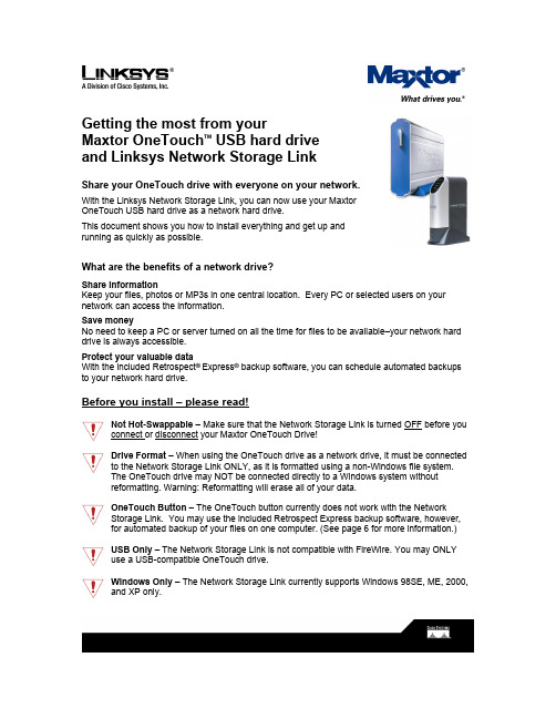
Getting the most from yourMaxtor OneTouch TM USB hard driveand Linksys Network Storage LinkShare your OneTouch drive with everyone on your network.With the Linksys Network Storage Link, you can now use your MaxtorOneTouch USB hard drive as a network hard drive.This document shows you how to install everything and get up andrunning as quickly as possible.What are the benefits of a network drive?Share informationKeep your files, photos or MP3s in one central location. Every PC or selected users on your network can access the information.Save moneyNo need to keep a PC or server turned on all the time for files to be available–your network hard drive is always accessible.Protect your valuable dataWith the included Retrospect®Express® backup software, you can schedule automated backups to your network hard drive.Before you install – please read!Not Hot-Swappable – Make sure that the Network Storage Link is turned OFF before you connect or disconnect your Maxtor OneTouch Drive!Drive Format – When using the OneTouch drive as a network drive, it must be connected to the Network Storage Link ONLY, as it is formatted using a non-Windows file system.The OneTouch drive may NOT be connected directly to a Windows system withoutreformatting. Warning: Reformatting will erase all of your data.OneTouch Button – The OneTouch button currently does not work with the NetworkStorage Link. You may use the included Retrospect Express backup software, however, for automated backup of your files on one computer. (See page 6 for more information.)USB Only – The Network Storage Link is not compatible with FireWire. You may ONLYuse a USB-compatible OneTouch drive.Windows Only – The Network Storage Link currently supports Windows 98SE, ME, 2000, and XP only.Installing the Network Storage Link and OneTouch Drive Connecting the Network Storage Link to Your Network1. Connect one end of an Ethernet cable tothe Ethernet port on the back of theNetwork Storage Link.2. Connect the other end of the Ethernetcable to your router.Figure 1. Connecting the Ethernet cable Connecting the OneTouch Drive to the Network Storage Link Important – Make sure that the Network Storage Link is turned OFF before you connector disconnect your Maxtor OneTouch drive!3. Connect one end of the included USBcable to your OneTouch drive.4. Connect the other end of the USBcable to the Disk 1 port on the NetworkStorage Link.Note: You can only connect up to twoFigure 2. Connecting the USB cable drives. Do NOT connect additional drivesusing a USB hub.Powering Up the OneTouch Drive5. Connect the round female connector fromthe power adaptor to the drive’s powerconnector6. Connect the two-pin female connector onthe power cord to the power adaptor.Figure 3. Connecting the power7. Connect the standard 3-pin electrical plug to an AC power outlet (preferably asurge-protected outlet).8. Turn on the OneTouch drive using the switch on its back panel.Powering Up the Network Storage Link9. Connect one end of the power adaptor to the back of the Network Storage Link.10. Connect the other end of the power adaptor to an AC power outlet (preferably asurge-protected outlet).11. Turn on the Network Storage Link by pressing its front panel button.The Network Storage Link may take up to three minutes to completely power up.During this time, the Ready/Status light will flash. When the Ready/Status light stops flashing and remains solid green, the Network Storage Link is ready for use.Note: For more information about the lights on the Network Storage Link, see Chapter 3:“Connecting the Storage Link,” in the Linksys User Guide.Installing the Linksys Software12. Insert the Setup Wizard CD into your computer.The Linksys Main Menu screen should appear after a few seconds.Note: If the main menu does not appear, see Chapter 4: “Setting Up the Storage Link,” in the Linksys User Guide.13. Click Setup.The Linksys software will search for the Network Storage Link connected to your network.When your Network Storage Link is found, the message: “Network Storage Link(s) Have Been Found!” will appear at the top of the screen and an icon and the name of your Storage Link will appear in the Selection Column.On the right side of the screen, you will see the IP Address of your Network Storage Link.14. Write down this IP Address. You will need it later to use your networked OneTouch drive. Note: If your Network Storage Link is not found, try clicking Search Again. If it is still not found, see Appendix A: “Troubleshooting” in the Linksys User Guide.Once your Storage Link is found, the next step is to format your OneTouch drive.Keep the Linksys setup screen open and proceed to the next section.Formatting the OneTouch Drive15. On the left side of the Linksys setupscreen, double-click the icon for your NetworkStorage Link.Figure 4. Network Storage Link IconA web browser will open and the Home page for your Network Storage Link will appear.Note: If your web browser does not automatically open, follow the steps in Chapter 6:”Configuring the Storage Link,” in the Linksys User Guide.Note: If you receive a “page cannot be displayed” message, you may need to change the IP address (URL) of your Network Storage Link. See Chapter 4: “Setting Up the Storage Link,” in the Linksys User Guide, for information about changing the Network Storage Link’s settings. If you change the IP address of your Network Storage Link, be sure to write down the new number,as you will need it to use your networked OneTouch drive after formatting.16. Click Administration.A window will open, asking you to enter your user name and password.17. Enter admin for both user name and password and click OK.The LAN page will appear.18. Click Advanced.The Groups page will appear.19. Click Disk.The Disk page will appear.20. Click Format Disk 1.Note: If your drive is connected to the Disk 2 port on the Network Storage Link, click Format Disk 2.The formatting process may take 15 to 30 minutes, depending on the size of your OneTouch Drive.Once it is finished, the message: “Formatted” will appear.21. Close your web browser and click No at the bottom of the Linksys Setup Screen. Note: For more information about the Linksys Web Utility, see Chapter 6: “Configuring the Storage Link,” in the Linksys User Guide.Using Your Networked OneTouch DriveTo use your networked OneTouch Drive, follow these steps:1. On the desktop, right-click the icon for yourcomputer and choose Map Network Drive.Figure 5. Mapping a Network DriveThe Map Network Drive windowwill appear.2. In the Folder (or Path) box enter theIP address of your Network StorageLink,followed by Disk 1 using thisformat:\\IP address\Disk 1.For example: \\192.168.1.77\Disk 1Note: Make sure there is a spacebetween “Disk” and “1” in the IP address.Note: If you changed the IP address inFigure 6. Entering IP Address of Network Storage Linkthe “Formatting the OneTouch Drive”section on page 3, be sure to enter thataddress here.Note: Reconnect at logon is automatically selected. This means that every time you logon in the future, you will automatically be connected to your OneTouch drive. You will find it alongside your computer’s main disks (C and D, for example) in the My Computer window.3. Click Finish.Windows will search the available networks for your Network Storage Link and a window will open displaying the contents of the Disk 1 directory on your OneTouch drive.Note: Two directories are automatically created for you on your OneTouch Drive. The Admin 1 directory is set up for only the administrator to use and will require a User ID and Password to be entered by any user accessing it from a computer other than the administrator’s. The Disk 1 directory, however, does not require a User ID or Password. You may create password-protected directories for additional users. See Chapter 6: “Configuring the Storage Link” in the Linksys User Guide for more information.Your OneTouch drive is now ready for use as a networked drive. You may drag and drop files to it, just like a normal hard drive.Network Backup SoftwareYour OneTouch drive includes Retrospect Express backup software, for easy, automated backup of your important files. If you would like to backup files from a computer on your network, follow the steps outlined in the next section.Note: You may only install the Retrospect Express software on one computer. However, you may purchase additional copies of Retrospect by going to: .Retrospect Software Installation:1. Go to Chapter 2: ‘Installing Your Drive’ in the Maxtor OneTouch User’s Guide.2. Find the Installing the Software section for your operating system.Your options are: Windows 2000 and XP or Windows 98SE and ME3. Follow the installation steps, choosing the Full Installation option.Note: When you have completed the software installation, do not proceed to the “Connecting the Drive” or “Setting up the Maxtor OneTouch Feature” sections.For step-by-step directions on how to back up your entire computer system using Retrospect, see the following section.Automated Network Backup Using Retrospect1. Open Retrospect.2. On the left side of the screen, click the + signnext to Automate and then click EasyScript.The EasyScript welcome windowwill appear.3. Click Next.The next window will ask you to choose yourbackup media.4. Select Disks and click Next.Figure 7. EasyScriptThe next window will ask you how many backup sets you want.5. Select I want one Backup Set for everything and click Next.The next window will ask you how often you would like to back up.6. Choose either Once a week or Every weekday and click Next.If you chose Once a week, you will choose the day and the start time.If you chose Every weekday, you will choose only the start time.7. Make your choice(s) and click Next.The Backup Summary window will appear showing the backup options you have chosen. The Start the first backup now checkbox is checked, which means your first backup will start when you click Finish.Note: It is recommended that you start your first backup now, because you will choose the source and destination of your backup, the first time you do it. If you choose not to start your first backup now, you will need to be at your computer for the first scheduled backup to choose the source and destination of your backup.8. Click Finish.If you chose the “Start the first backup now” option, Retrospect will scan your drive and the Backup Set window will appear. You will now choose the disk where your backup files willbe stored.9. Double-click My Network Places.The Adding Network Volume window will appear.10. Click Advanced.A window will open, asking you to enter the UNC path for the volume.11. Enter the IP address of your Network Storage Link,followed by Disk 1 usingthis format:\\IP address\Disk 1. For example: \\192.168.1.77\Disk 1Note: If you changed the IP address in the “Formatting Your Drive” section on page 3, be sure to enter that address here.12. Click OK.Disk 1 will now appear under My Network Places in the Backup Set window.13. Select Disk 1 and click Proceed.The Add New Member window will appear to confirm your backup destination.14. Click OK.The backup will now start.Note: Your entire computer system (including all of its drives) will automatically be backed up. Depending on the size of your system and the speed of your network, this process may take as much as several hours. For example, on a home wireless network of less than 10 megabits per second, a 10 gigabyte backup would take over three hours.If you wish to change the specific items that are backed up or learn how to restore files from a backup, see the Retrospect online help in the Retrospect Express software.When the backup is finished, you will see the message: “Execution completed successfully.”Congratulations. You have completed your first backup. Future backups will take place automatically on the days and times that you selected, as long as the computer, OneTouch drive and Network Storage Link are turned on.。
用友软件u8系统用户操作手册(UFIDAU8systemusermanual)

用友软件u8系统用户操作手册(UFIDA U8 system user manual)UFIDA U8 system user manualI. system managementMain function:Reconciliation of sets of management, including the establishment, modification, backup, recovery, and delete accounting data.Unified management of the annual accounts, including the establishment, transfer, clear annual data, last year the data backup and restore the annual account data.Conduct unified planning, management and maintenance of operators and their rights.Clear the documents, lock, clear the abnormal tasks in time, etc..UFIDA Software default, the only system administrator for Admin, the initial password is empty. (suggest to reset the password)(1) how to set up accounts?The starting procedure UF ERP-U8 system service system management system (Admin operator) to determine the registration menu "account set menu set to enter the relevant account information (including account opening name, unit name, date, accounting system, accounting industry level dataaccuracy and length, etc.)(two) how do I set up an operator?Register with Admin, login, system management (i. e., the first 8 operations), permissions menuThe user adds input operator information (including operator code, name, password) to increase (increase here, confirm save)(three) how to set operator permissionsLogin system management with Admin identity (ibid.) "permission" menu permission first select the permissions set of account and accounting year, and then select the user to modify the authorization (i.e. in the relevant operation authority before me your attention, "+")If you want to set a user account manager, can be directly in the "tick" Account Supervisor(four) how to backup the accounting data?The system provides two backup modes: automatic backup and manual backupI. automatic backup: first, build a new folder on the local hard disk. The folder name is set as "UF automatic backup"". Then register with Admin, login system management (ditto), system menu"Auto backup plan" and "increase" input automatic plan number, automatic program name, the "frequency" for a week, "days" and "start time" is set according to the actual situation of the unit, "days" set for 7 days have already established a good selection of UF automatic backup folderThe last hit tick account and annual to choose the backup, click Add.Two, manual backup: first, on the local hard drive to build a new folder, folder name is set as "year + month + day manual backup", such as "20060925 manual backup."". Then take the Admin identity login system management (ditto) "account set menu" output "to choose the backup account check the system will automatically compress the process, wait a moment," select the backup "select just established" 20060925 manual backup "folder, click" confirm "" hard disk backup completed. "Ok. Finally, find the "20060925 manual backup" folder, and you will find two files, which show that manual backup is successful.Two, enterprise portal(1) basic setting1, operation methodRegister with operator as login, login, UF, U8 enterprise portal settings (enterprise portal, lower left), basic files2, special reminderThe content of the basic archives should be set according to the actual situation, not every item should be set up."Customer classification" refers to the unit in the day-to-day operation of the customer classification, and its classification standards are generally based on unit statistics need. So is the supplier classification. When setting, you must set the category and then set the file. If the customer is not selected when the account is set up, the supplier classification is not entered.In the setting of accounting subjects, if a subject chooses auxiliary accounting, then the subject does not need to set down subordinate detailed subjects, and the relevant detailed items are set in the corresponding basic setting. If the account receivable account, if the choice of auxiliary accounting "customer contact", then the subject of the relevant details should be set in the customer file.account setup is complete, or in new cash, bank subordinate subjects, such as the need to specify the cash bank accounts and cash flow based subjects, procedures for enterprise accounting archives portal settings specified to edit the specified subjects.When the initial balance is entered, the initial balance of the enterprise portal business ledger is set at the beginning of the entry periodIf a subject counts for quantity and foreign currency, the amount of the initial period and the balance of the foreigncurrency should be entered at the beginning of the entry period, and the amount of the local currency must be entered first, and then the amount of foreign currency balance will be entered.Non final course (data column is yellow), the balance is automatically calculated according to the balance of detail items.Red balance minus input?.The initial balance at the end of the certificate is read-only and cannot be modified.After the initial entry, the trial balance is made and the daily work can be done after the balance.(two) daily operation2.1 fill in the certificate1. document number: the system defaults automatically in chronological order. If you do not need the system automatic number, please hand number.Need to write the document number manual (mainly in vouchers, prompt whether vouchers off, "select" no "case), click the [[settings]] - GL - [options], click the" Edit "," modify system number "to" manual ", finally ok. This option can be modified at any time.2. if the subjects set the auxiliary accounting attribute, inthe fill in the certificate when the system will automatically prompt supplementary information, such as departments, individual projects, customers, suppliers, such as the number of. The auxiliary information entered will be displayed in the notes below the document.3. if you want to give up the unfinished entry input, according to the "line" button or the [Ctrl+D] key to delete the current entries.4. if you fill in the certificate used by the subjects for cash flow in the end of this article subjects recorded entries after the specified project cash flow of the entries as required. A conditional entry can be specified as a plurality of cash flow items, but the total amount must be consistent with the amount of entries. For the cash flow of the subject is not specified, such as specifying the project cash flow, in a record amount of input, click "flow" button, will pop up the cash flow of the specified window, ask you to enter the condition entries corresponding to the project cash flow.5. modify and delete documents5.1 modify the certificate must be modified in the "window" to fill in the certificate.In 5.2 after the lack of follow-up treatment, signed audit, directly find the need to modify the document can be modified.5.3, after the audit found the error, need to modify, cancel the audit directly, return 5.1 to modify.5.4, after accounting errors found, you need to modify, you need to cancel the account, cancel the audit and other operations, return 5.1 to modify.5.5, after checkout found errors, need to modify, you need to cancel the bill, cancel the account, cancel the audit and other operations, return 5.1 to modify.5.6 documents need to delete, in the "fill in the certificate" window, click on the [] - [single / recovery] will certificate void void. Click again [to make a copy of the document], select the month, click [OK]. At this point, the system will appear "whether the collation document broken" prompt window. If you need to retain the certificate number, select "no" and "yes", then the system automatically fills the document number.Note: the account must be final; the sum and the sum are not null; the scarlet letter is represented by "-". The cost of subjects, such as financial expenses in subjects, fill in the certificate, must be done in the debit, debit or debit (click on the blue and scarlet letter on the keyboard "-"). Otherwise, the number of reports is uneven.2.2 audit voucherNote: the audit and not made is the same person; leaflets or batch audit audit; cancel the audit by the audit can only cancel the signature signature; a certificate cannot be audited, modify, delete, cancel the audit is only the sign before they can modify or delete.2.3 billingShow the accounting report, for example, you want to pay the vouchers, some documents are not audited or not signed by the cashier, belong to the vouchers can not be accounted for, you can modify the prompt, and then billing. The following interface appears.When the progress bar is complete, the system will pop up and the account will be completed.2.4 period profit and loss carry over definition and transfer generation1. define period profit and loss carry over: click the [transfer definition] under the main menu [end of the system] and click [period gain / loss] to enter this function. Screen display [duration gain / loss setting] interface. At this time, in the "current profit account", enter the profit account for this year, click [determine], define the completion.2. period profit and loss carry over: click "transfer generation" under the system main menu [End], click [period profit and loss carry over] enter this function. The right window shows the [transfer generation] interface. Click [Select], then the system will automatically generate the certificate. At this time, you need to review and record this voucher.Note: the gains and losses during the transfer, check to do thismonth's daily business vouchers are accounting, if not accounting vouchers, in turn, the system will automatically prompt, if have accounting, can be carried forward.2.5 checkoutClick the checkout at the system main menu [end of the month] to enter this function. The screen shows the checkout wizard one - select the checkout month. Click the checkout monthClick "next",The screen display checkout wizard two checks the booksThe button in the "reconciliation", to check the system in checking accounts, in the reconciliation process, according to the "stop" button to suspend reconciliation, reconciliation is completed, click "next", the screen display checkout wizard three monthly report:Reconciliation is completed, click "next", the screen display checkout wizard three monthly report:If you need to print, click "print" to print monthly report. Click "next", the screen display four to complete the checkout checkout WizardIf you meet the requirements of the system will check, check, according to the "checkout" button to complete the work this month.If the bill does not meet the requirements, the system will not check out, appear belowClick "next", see the work report to find the reasons, revised again to check out.Note: checked the month can not fill in the certificate; there is no accounting voucher in the bill not; data backup advice before closing, to ensure the security of the data.2.6 cancellation of account and cancellation of accountA cancel the checkout: in the checkout wizard, you can select the month when you want to cancel the checkout, while holding the [Ctrl+Shift+F6] key on the keyboardB. cancel billing: in the reconciliation interface, while pressing the < Ctrl + H > key on the keyboard, the display / hidden menu will restore the status menu before loggingPress the < Ctrl + H > key before the certificate menu Press < Ctrl + H > after the keyChoose to return to the state at the beginning of the month? UFO report operationI. Introduction of basic concepts of UFIDA reporting system1, the system provides three major reports automatically fetching function: balance sheet, income statement, cash flow statement.2, report editing status: there are two kinds, one is "data" state; one is "format" state (report window left bottom) display.Format: mainly used for report format design, in the format of the state of the operation of this report, all tables and pages have an effect. In the format state, you can't do data entry, calculation and other operations. In this state, you can only see the report format, and all the report data are hidden.Data: mainly used for reporting data processing, through the fetch formula to take out the ledger data, in this state, used to manage the data of the report, such as input, audit data, increase or delete table, and other functions.Formats and data states can be transformed from one another to another3, table page: a UFO report can accommodate up to 9999 table pages, the table page in the "data" status can be increased or deleted, each table page data can be different.Two. Daily operation1., in the local hard disk new "UF report" folder, and then according to account sets and months to establish sub folder, easy to report storage.When 2. or three big reports need to be taken, click on the file above the window of the report window "open" to find the folder where the report is located, and select the folder you want to fetch.3. in the data status, you can automatically fetch from the ledger from the data above the key window - keyword entry - as follows.Take the number from the account: first, in the "data" status, enter the key word, enter units and date, date and other informationTo determine whether the system pop-up prompt retry, point "yes", starting from the system account access4 insert / append / delete table pageIn the data status, click "Edit" - insert "table" page, and others can refer to this method.Note: 1., after each time you take the data, you should pay attention to the preservation, so that next month can be built on the basis of the last few months. At this time you can add or insert a new tableTake the number 2. cash flow statement, need to be adjusted totake the number of system time month, for example: take the data of October, the bottom right - click the computer time, then there will be a window will be changed to October to january.。
ABB 风力发电变流器预防性维护手册 ACS800-67 双馈风力发电变流器说明书

预防性维护手册ACS800-67双馈风力发电变流器相关用户手册标准手册代码 (中文)ACS800-67用于异步发电机的风力发电传动单元硬件手册3ABD00018827ACS800-67 并网柜 硬件手册补充手册3ABD68583161 Emax安装和操作说明手册1SDH000460R0002 ABB断路器风电项目维保方案SPC201200601ACS800-67预防性维护检查表3ABD00030320您可以在Internet上查找PDF格式的手册和其他产品文件。
请参阅封底内的Internet 上的文件库一节。
对于“文档”资料库内没有提供的手册,请联络您当地的ABB 代表。
预防性维护手册ACS800-67 双馈风力发电变流器北京ABB电气传动系统有限公司版权所有3ABD00031435 版本 B 中文生效日期:2014-1-151安全须知•只有具备资格的电气工程师才允许对变频器进行维护和检查!•在进行任何维护工作之前,必须断开发电机的定子和 ACS800-67 的电源(箱变二次侧或一次侧开关必须断开),强烈建议使用机械抱闸装置锁住发电机的转子。
•等待至少5 分钟,以确保中间电路电容器放电完毕•完整的安全须知在《用于异步滑环发电机的ACS800-67风力发电传动硬件手册》(3ABD00018827[中文]) 开始部分有描述。
维护重要性请务必遵循此维护手册对空冷型风电变流器进行定期专业的维护,否则有可能导致变流器使用寿命缩短,甚至造成故障或损坏。
•如果不对断路器进行定期维护,可能引起断路器功能失效,从而造成变流器严重损坏。
•如果不定期更换空气滤网,引起滤网堵塞,会造成变流器过温,或使柜内电力电子器件和电容长期运行于高温环境下,导致寿命缩短,甚至损坏。
•LCL滤波器维护可以提前预防滤波器电容损坏,否则有可能造成电容炸裂。
•如果不对控制器件、加热冷却系统等进行定期维护,有可能影响变流器的正常运行,丢失故障信息,甚至造成变流器的故障或损坏。
风力发电机调试

Reactive Power Limit 无功限幅 20.23 USER KVAR LIMIT (0~110% 55%) reactive power limit
ABB
发电机切入 / 切出速度
20.21 SWITCH ON SPEED 切入速度 Default 950rpm above this speed limit to allow the stator to be connected to the grid
ACS800-67 调试指导
Zhang Chi
ABB
ACS800-67 调试步骤
双馈风力发电系统构成 变流器动力电缆及控制电缆连接 通电前的检查 转子侧变流器INU参数设置
网侧变流器ISU上电测试
与电网同步测试(禁止并网开关合闸) 发电机并网
调试注意事项
ABB
ACS800-67 系统构成
16.14 FAN SPD CTRL MODE
ABB
通讯类型 16.11 COMM PROFILE
ABB
电机启动数据 99组 START-UP DATA
ABB
发电机额定功率
99.06 MOTOR NOM POWER
ABB
发电机等效电路参数
99.21 Rs...99.25 Rr 发电机等效电路:
20000(Integer value from fieldbus) ~ 50.01
50.04 PULSE NR (1~10000)
The number of encoder pulses
50.12 SP ACT FILT TIME (0 ~ 10000s)
DeviceMaster系列产品操作手册说明书

Windows Manual Driver Removal and CleanupIncludes these products: DeviceMaster RTS, DeviceMaster Pro, DeviceMaster Air and DeviceMaster SerialHub.Note: This same procedure is used for all of the Windows OS’s, but the directory path structure is slightly different. Wherever you see in this document, "c:\%system%\", substitute; "c:\Windows" or “C:\WINNT” as the new path for your Operating System. Depending on the version of Windows you are using, you may notice that some of the screen shots included in this document are different than what you see on your PC. There should be few enough differences that you will not experience any difficulties.Keep in mind that whenever a system is changed, it is always a good idea to have a full backup for recovery purposes should something undesirable take place. See your Microsoft documentation for instructions on backing up your registry and/or system hard drive.When removing your DeviceMaster with the intent of updating drivers, start by getting the following basic information from each unit. The MAC address and the IP address assigned to the DeviceMaster with the com numbers assigned with the appropriate ports settings. This information will be used to configure the new drivers to maintain the same MAC, IP and port settings to avoid having to re-arrange serial cables or change settings in your application.In Windows Device Manager select Multi-Port Serial Adapters and expand the category to list the installed devices. Double click on one DeviceMaster at a time to open the properties pages. Make notes of the following information.Use the “Network Connections” tab to collect the MAC and IP addresses assigned to t his DeviceMaster.Use the “Port Settings” tab to collect the Com numbers assigned to this DeviceMaster.Click on the com number and select the “Properties” button to collect the port configurations if different than default.After the settings have been notated, close the properties page.Highlight the Comtrol product and right click to select “Uninstall” from the pop-up menu.Repeat for each Comtrol product.When prompted to restart PC respond 'No'.Close Device Manager.In the following procedure, be aware that not all entries will be present. That is normal due to the driver removal procedure already completed. In the event the entry does not exist, just continue to the next step.Open Windows Explorer by right clicking on the “Start” button and selecting “Explore” from the pop-up menu.Manually delete the files listed in File Deletions: below. Use the path of \winnt\ or \windows\ as appropriate for your PC. Note: The \inf\ directory is normally a hidden system directory. To view this directory, go to the ‘Tools’ drop-down menu and select ‘Folder Options…’. Select the ‘View’ tab and set all of the options as shown here, then click ‘Apply’ and ‘OK’.File Deletions:del c:\comtrol\*.* This folder may not exist due to different versionsdel c:\Program Files (x86)\Comtrol\DeviceMaster\ All files and all subfolders in this folder (64bit system)del c:\Program Files\Comtrol\DeviceMaster\ All files and all subfolders in this folder (32bit system)del c:\%system%\inf\ctmaport.infdel c:\%system%\inf\ctmaport.pnfdel c:\%system%\inf\ctmproto.infdel c:\%system%\inf\ctmproto.pnfdel c:\%system%\inf\ctmsport.infdel c:\%system%\inf\ctmsport.pnfdel c:\%system%\inf\netctmrk.infdel c:\%system%\inf\netctmrk.pnfdel c:\%system%\system32\ctmnslnt.catdel c:\%system%\system32\ctmsclas.dlldel c:\%system%\system32\ctmsclasx64.dlldel c:\%system%\system32\ctmsport.infdel c:\%system%\system32\sisetup.dlldel c:\%system%\system32\sisetup.chmdel c:\%system%\system32\sisetupx64.dlldel c:\%system%\system32\drivers\devmast.bindel c:\%system%\system32\drivers\devmast2.bindel c:\%system%\system32\drivers\rpshsi.bindel c:\%system%\system32\drivers\rpshsi2p.bindel c:\%system%\system32\drivers\rpshsi.sysdel c:\%system%\system32\drivers\rpshsix64.sysdel c:\%system%\system32\rpshsi\*.*del c:\Windows\System32\DriverStore\FileRepository\netctmsi.inf* (see section “FileRepository” below)del c:\Windows\System32\DriverStore\FileRepository\ctmproto.inf* (see section “FileRepository” below)del c:\Windows\System32\DriverStore\FileRepository\ctmsport.inf* (see section “FileRepository” below)The last three files will have long extensions and if the wildcard (*) is not used, the files will not be located.After deleting the above files, you must locate some additional specific .INF and .PNF files. When a DeviceMaster driver is installed, Windows creates at least three additional .INF and .PNF files under the %SYSTEM%\inf hidden folder. They will be named oemX.INF and will be accompanied by an oemX.PNF where X is some number, and is the same for both files. The .inf file is a text file that will open in Notepad when it is double clicked. Open each, and every one, of these INF files in notepad and find the ones that pertain to the Comtrol. There may be multiple instances of each of these files, so be sure to continue to check all of the oemx files.It will show something like this at the very top of the file:; ---------------------------------------------------; netctmnsl.inf - NS Link install script(WinXP) INF file.; Comtrol Corp., Handles the Device.;; Inf for Windows XP; ---------------------------------------------------Here are the lines that you will be looking for in the .INF files. This is the first line of text in the INF file, so you do not need to look past the first line of the file.netctmnsl.inf - NS Link install script (WinXP) INF file.CTMPROTO.INF -- RPSHsi Protocol DriverCtmSPort.inf – NS Link port install script INF fileRemove both the INF and PNF files of the same number. NOTE! Delete ONLY Comtrol INF and PNF files! Other INF and PNF files are used for other products such as video cards, printers, etc. Removal of these other INF files could severely impact the operation of your PC.You may discover an INF file that shows this text for the first line;PVDrv.INF – PortVision Plus NDIS Protocol DriverThis file and the associated PNF may be left as is, without deletion, as these files are used by PortVision Plus.Editing the Registry:(Caution:Before editing the Registry, it is highly recommended that you perform a backup of the registry. Consult your Microsoft Windows manuals for information on registry backup procedures. Any careless editing in the registry may cause irreparable damage with disastrous results, possibly requiring a reinstall of the Microsoft Windows operating system.) Run Regedt32 and make the following modifications. Please note that you may not have some of the folders referenced here. The driver removal may have already correctly removed the folder; in which case do not be concerned if it is not present. If while attempting to delete one of the keys, a message is displayed saying it is 'unable to delete this key' permission needs to be set. While the desired key to delete is highlighted, go to the ‘Edit’ o r 'Security' drop down menu (dependant on OS) in the command bar and select 'Permissions', then select 'Everyone' and place a checkmark in the 'Full Control' option. Now when you try the delete, it should be successful.HKEY_LOCAL_MACHINE on Local MachineSYSTEM|--ControlSet001|--Enum| |--CtmPort| | |--SiPort <-- Delete this folder| | |--1&173424ed&2&Portxxxx (where xxxx is a 4 digit port number)| | |--Additional listings of same format| |--Root| |--MULTIPORTSERIAL| |--0000 <--Delete this folder IF Mfg= Comtrol Corporation|--Services| |--rpshsi <-- Delete this folder including the subfolders| |--Enum| |--+Parameters| |--Security| |--rpshsix64 <-- Delete this folder including the subfolders| |--Enum| |--+Parameters|--Control|--COM Name ArbiterRight column - edit the key 'ComDB'Double click ComDBData edit window opensModify the data so the data shows 03 00 00 00 00 00 …Click OKOptionally, repeat this process in HKEY_LOCAL_MACHINE\SYSTEM\ControlSet002 Close regedt32.Reboot PC and check Device Manager and Event Viewer for any errors.Correct any and all errors reported by Event Viewer.FileRepositoryTo delete the entries in the FileRepository folder requires special procedures.For a 64 bit Operating System the folders are located here and named as:C:\Windows\System32\DriverStore\FileRepository\netctmsi.inf _amd64_*C:\Windows\System32\DriverStore\FileRepository\ctmproto.inf_amd64_*C:\Windows\System32\DriverStore\FileRepository\ctmsport.inf_amd64_*For a 32 bit Operating System the folders are located here and named as:C:\Windows\System32\DriverStore\FileRepository\netctmsi.inf_x86_neutral_*C:\Windows\System32\DriverStore\FileRepository\ctmproto.inf_x86_neutral_*C:\Windows\System32\DriverStore\FileRepository\ctmsport.inf_x86_neutral_*(The numbers following the word neutral will be different in each PC)Download Sysinternals PSTools from Microsoft and extract to a clean folder:https:///en-us/sysinternals/bb897553.aspxOpen a command window (run as admin) in the extraction folder and enter “psexec –s cmd” (without quotes) and press Enter.This should open a command window in ‘System’ mode (The title bar should now show \\PC_NAME:cmd and change to the c:\windows\system32 folder)At the c:\windows\system32> command prompt enter “cd driverstore” (without quotes) and press Enter.At the c:\windows\system32\driverstore> command prompt enter “cd filerepository” (without quotes) and press Enter. You should now be in the C:\Windows\System32\DriverStore\FileRepository folderAt the command prompt enter “dir ctm*” (without quotes) and press Enter.This will show any Comtrol folders that are to be deleted.At the command prompt enter “cd [the folder name discovered in the previous step].”(without quotes) and press Enter. Use caution as typos will prevent success.This will change your prompt into this folderAt the command prompt enter “dir” (without quotes) and press Enter.This will list the folder contentsAt the command prompt enter “del *.*” (without quotes) and press Enter.You may be prompted to confirm.This should delete all contents of this folderAt the command prompt enter “cd..”(without quotes) and press Enter.This will take you back one folder level.At the command prompt enter “rd [the folder name discovered in the previous step]” (without quotes) and press Enter.This should remove the folder.Repeat for all ctmsport.inf_ foldersRepeat for all ctmproto.inf_ foldersRepeat for all netctmsi.inf _ foldersReboot the PC。
罗技5075B Plus键盘用户手册说明书
键盘用户手册User ManualBenutzerhandbuch快速开始指南系统需求Window s®XP / Vista / 7 / 8 / 10或更高版本安装步骤将键盘USB连接线插入电脑的USB接口即可开始使用。
独立指示灯5075B Pl us 组合键功能5075B Plus 系统功能 (Windows)Fn + 左Win锁Win键长按 Fn + ~ 3秒恢复出厂设置长按 Fn + 右Ctrl 3秒切换菜单键5075B Plus系统功能 (Mac)F1F2F3F4降低显示屏亮度增加显示屏亮度开放任务控制呼出SiriF7F8F9F10上一曲播放/暂停 下一曲静音F11F12左Win 左Alt调低音量调高音量OptionCommand右AltCommand5075B Plus灯光调节灯光速度变慢灯光速度变快灯光变亮灯光变暗灯光方向向左灯光方向向右灯光关闭/开启常亮、涟漪、如影随形、川流不息、 流星繁星点点、霓虹、光波、层出不穷、彩泉涌动呼吸、极光、正弦波、雨滴、峰回路转斜风细雨、踏雪无痕、聚合、一石二鸟、百花争艳切换背光至7种单色+R GB循环切换侧光至7种单色+RGB循环侧边灯光模式切换,包括关闭 共6种FN+-FN+=FN+↑FN+↓FN+←FN+→FN+L FN+Z 侧边灯光亮度切换,5档,循环FN+Home FN+PGUP FN+EndFN+PGDW FN+\FN+AltFN+左Ctrl5075B Plus 连接使用指南蓝牙配对键盘开机后,按下FN+E/R/T进入蓝牙模式,长按FN+E/R/T组合键3S,键盘进入对码状态,蓝色指示灯快闪,连上后指示灯常亮2S,如果没有连上设备指示灯熄灭,键盘进入睡眠。
2.4G配对键盘开机后,按下FN+Y进入2.4G模式,再按下FN+Y组合键3S进入配对模式后,插入接收器,指示灯快闪,配对成功后退出对码,模式灯常亮2S,找不到配对设备30s后,退出对码模式灯熄灭,键盘进入睡眠。
GPS绘图软件(OziExplorer)使用手册
GPS 绘图软件(GPS Mapping Software)使用手册 OziExplorer(Version 3.95.4.H)审校:闫建强整理:张精明中油东方地球物理勘探公司综合物化探事业部2005年4月目录前言 (1)1 软件安装 (2)2 界面认识 (3)3 主菜单栏选项 (3)3.1文件(File)菜单 (3)3.2 选择(Select)菜单 (7)3.3 视图查阅(View)菜单 (7)3.4 地图图像(Map)菜单 (8)3.5 选项设置(Options)菜单 (9)3.6动感地图(Moving Map)菜单 (11)3.7 导航(Navigation)菜单 (12)3.8 三维和高程(3D/Elevation)菜单 (12)3.9 Garmin(导航仪传输)菜单 (18)3.10 Help(帮助)菜单 (19)4 工具栏菜单 (20)4.1 在地图上显示和设置航点 (20)4.2 在地图上显示和设置航迹 (21)4.3 在地图上绘制航点间线段 (22)4.4 在地图上量取距离 (24)4.5 在地图上添加文字说明 (25)5 地图校准 (26)6 实例图片 (31)7 TGO测量软件与Oziexplorer软件的结合 (34)7.1从TGO向Oziexplorer导出数据 (34)7.2从Oziexplorer向TGO导入数据 (37)7.3航点和航迹数据文件的共享 (38)8 相关网站 (39)9 结束语 (40)前言由澳大利亚推出的GPS绘图软件(OziExplorer3.95.4.h)是一个功能非常强大的软件,它可支持Garmin, Magellan, Lowrance, Eagle, Silva/Brunton andMLR等型号的导航仪数据(航点,航迹,路线等)的编辑处理及上下装等工作。
该软件相对Garmin类型导航仪自带的MapSource软件功能要强大,是测量人员在实际应用中的得力助手。
ACS800系统软件固件手册
警告! 有些部分,比如柜体里的功率半导体器件的散热器,在断开电源 后,还会在一段时间内保持很高的温度。
ii
ACS 800 固件手册系统软件 7.x
目录
安全须知 ................................................................................................................................................................. i 安全须知概述 ............................................................................................................................................... i
KODAK PROFESSIONAL DCS摄像机用户手册说明书
inconsistent firing of the strobes or damage to your camera’s circuitry. • Use of a safe sync is recommended. It isolates your camera’s flash trigger circuitry from
IEEE 1394 port Video port Serial port
Battery slot Remote Control sensor
Digital Status LCD
Quickly access digital functions using Digital Status button and Five-way Control.
1. Insert the power module into the battery slot on the camera and turn the latch clockwise.
2. Connect the DC cable to the power module and Charger/Adapter.
• Consider saving your Raw images when saving JPEG images. You may perform image edits if you have the Raw image file and also change the image’s resolution based upon your output needs. (See the User’s Guide for saving Raw images in Advanced mode.)
- 1、下载文档前请自行甄别文档内容的完整性,平台不提供额外的编辑、内容补充、找答案等附加服务。
- 2、"仅部分预览"的文档,不可在线预览部分如存在完整性等问题,可反馈申请退款(可完整预览的文档不适用该条件!)。
- 3、如文档侵犯您的权益,请联系客服反馈,我们会尽快为您处理(人工客服工作时间:9:00-18:30)。
第六章- 趋势1.监测和数据记录器DriveWindow软件可以显示和控制2种趋势:•监控•数据记录仪在DriveWindow软件窗口区域的下两个窗格保留用于设定和显示的趋势。
较低的左侧窗格中,趋势设置面板中,用于显示和更改设置。
右下方的窗格中,趋势显示窗格,用于显示图形格式趋势。
该面板是由监视器和数据采集器共享。
趋势设置面板中包含两个选项卡,你用它来选择,是否显示,更改和控制显示器或当前选择数据记录仪。
当您选择显示器,数据记录器的设置和趋势都隐藏和控制是禁用。
当您选择了数据记录器,监视器设置和趋势都隐藏和控制是禁用。
该数据记录器窗格由所有数据采集器共享。
当前数据记录器是通过选择选择该驱动器在浏览树窗格。
如果驱动器有两个数据采集器,驱动器数据记录器选择无论是在浏览树窗格中,从数据记录器菜单中,或者从数据记录器的上下文菜单显示。
OR如果驱动器有两个以上的数据采集器,驱动器数据记录器选择了类似的方式,在案例二数据记录器。
但是,菜单显示下一个数据记录器,而不是数据记录器2的点击接下来数据记录器会将数据记录器驱动器选择下一个数据记录器。
注意,下最后一个数据记录器的是第一个数据记录器。
OR请注意,所有数据记录器的设置和显示的数据记录仪特有的。
所以,当你改变数据记录器的设置,例如,它仅涉及当前选定的数据记录器。
所有其他的设置数据采集器将被保留。
您可以验证从在标题所示的OPC地址当前选定的数据记录仪数据记录器显示窗格。
如果一个驱动一个以上的数据记录器,DL1,DL2,等等中的标题显示,这记录仪的显示。
除了查看趋势,还可以打印和出口趋势。
1.1.1监视器监控运行,并在你的电脑中收集数据。
收集通过读取周期性监测的项目进行从驱动器。
物品可以驻留在不同的驱动器。
值被绘制在实时监视显示窗格中,当监视器正在运行。
如果暂停显示器,显示器的显示面板的更新是停止,但数值仍在背景收集。
暂停期间收集到的值绘制,当你命令监控继续。
注意!Windows不是一个实时操作系统。
这意味着,在实践中,即使测量循环完成后,它们不以相等的时间间隔进行。
负载引起的Windows内核驱动器可能会导致测量中断,这令的数百毫秒。
测量值是时间由DriveOPC可以加盖。
图形绘图包,但是,是能够仅做该图中,如果测量间隔被假定为是恒定的。
因此,该绘制点实际上是从测量值估计。
如何估计完成取决于监测图首选项中选择可视化的方法。
1.1.2数据记录器数据采集器驻留在硬盘。
数据由驱动收集。
采集可以通过一个特定的停止命令或触发条件成为真正停止在驱动器中。
比那些影响数据记录仪显示(x轴的长度,y最小值的所有其他数据记录器设置,并最大,缩放)被保存在驱动器中。
它们被保存在驱动器中它没有,即使功率。
然而,当一个数据记录器被上载,在DriveWindow软件当前设置被冻结,所以设置显示上传的趋势的设置。
这是不可能的,以查看在实时数据记录器的趋势。
1.1.3设置在您开始监控或数据记录仪,通常必须更改其设置,例如作为渠道监控或记录,测量间隔等。
请注意,您不能使用DriveWindow软件来更改本地DriveDA OPC服务器的数据记录器设置驱动器(AC880系列)。
你只能够控制ACS880系列变频器和变化的数据记录仪常用的设置。
也只有六个信道可以示出虽然有可能在多个信道驾驶。
一些常用的设置,影响的趋势显示,你可以以后也改变开始。
大多数设置是通过使用一个对话框,与一个或多个编辑字段输入。
当对话框提出,该字段包含的设置当前值被改变。
其中之一被选择,那么如果你开始输入时,显示值立即覆盖。
如果该值可以是负的,它可以任选地通过一个加号之后。
实际值可以给定值作为一个整数,太。
一个真正的数字可以用可选的指数结束,这是由e 或E开头。
该指数可以签署。
请注意,在实际小数点符号数字是期间无论区域设置。
例如:1.2,-1.23E-3,1E3。
当编辑,您可以使用正常的Windows快捷方式和编辑键,如箭头键,Home,最终,德尔等按键,使用或不按Ctrl和/或Shift键不放。
注意,但是,该按Esc关键是不要点击取消按钮并按下回车键同单击确定相同按钮。
如果值是无效的,当您单击确定按钮,将显示一条错误消息。
你必须承认错误消息,编辑无效值或取消操作。
虽然运行的(虚拟)内存的可能性是最大的,当你设置的大小监视历史缓冲区或监视时间间隔,它是,在理论上,可以同时改变的任何设置。
要更改的设置被接受,但设置的组合不能被用来DriveWindow软件。
当你耗尽内存,你会得到一个错误信息:趋势显示窗格中被清除。
你必须改变一些设置,以摆脱外存储器条件。
1.1.4控制显示器可以通过启动,暂停,继续,停止和清除它来控制。
数据记录器可以通过启动,停止,触发,清除和上传进行控制。
该上传的图可以被清除了。
1.1.5图表首选项您有几个选项来控制图的前景。
绘图点可以连接各种方式。
您可以控制,比例是如何显示和输入。
图形指针的显示有一些选择。
从在监视器测量值估计所述绘图点的方法可以改变。
屏幕和彩色打印机趋势颜色可以改变。
趋势线的风格是可以改变的,分别为屏幕,黑白打印机,彩色打印机。
1.1.6查看的监测和数据记录器的发展趋势看颇为相似。
您可以水平和垂直滚动。
您可以向内缩小,向外,并重置缩放。
您可以检查使用图形光标的趋势。
您可以临时更改所选图形光标数值的显示格式。
您还可以更改像x轴的长度,Y最小值和最大值,以及缩放设置(数据采集器只),同时观察的趋势。
1.1.7保存和恢复由于DriveWindow软件的版本2.10,趋势可以保存和恢复。
1.1.8打印和导出监视和数据采集器的发展趋势可以打印,复制到剪贴板,并出口(以数字文本格式)。
另请参见:窗口区域浏览树窗格趋势设置窗格趋势显示窗格2.共同趋势设置显示器和记录器有以下共同设置,影响到的显示相应的发展趋势:•X轴长度(秒)•Y轴的最小和最大•Y轴适应,这实际上是另一种方式来改变y轴的最小值和最大值•不同渠道的缩放除了一些例外,这些都可以在任何时候改变:•当一个趋势,在趋势显示窗格中绘制Y轴只能适应。
•一个显示器频道的不同通道的缩放,而显示器是不能改变的运行。
注意!一个显示器频道的缩放的改变需要监控的发展趋势是从重绘的开始。
如果你有大量的监控数据,这可能需要很长的时间。
常见的设置保存到并从工作区恢复。
另请参见:监控和数据记录器趋势设置窗格监控菜单数据记录器菜单恢复默认设置2.1设置X轴长度您可以设置监视器或随时记录仪的x轴的长度。
注意,缩放通常也改变x轴长度。
数据记录器的X轴的长度也可以自动在数据记录器上载更改。
如果x轴长度比数据记录仪信道缓冲器的大小大,如果是小于的间隔中,或者如果它是不的时间间隔,x轴长度的多个自动设置为数据记录器的信道缓冲器的大小。
请注意,如果一个数据记录器从未上传,DriveWindow软件,不知道肯定的大小数据采集通道缓冲区。
因而DriveWindow软件没有做任何检查关于x轴的长度,直到它知道更多关于数据记录器。
当数据采集通道缓冲区的大小是已知的,DriveWindow软件不接受不正确的设置的x轴长度。
然而,当数据记录器的时间间隔被改变,x轴长度不检查,和因此可能具有不适当的值。
在这种情况下,数据记录器的载自动设置x轴长度。
需要注意的是改变x轴的长度只影响当前缩放级别。
向外缩放或缩放复位恢复先前的或基层x轴设置。
要改变x轴的长度,可以双击趋势设置面板中X轴长度(S)字段,或者在轴子菜单,可以在显示屏中发现选择X长度命令的上下文菜单显示器设置,数据记录器菜单,数据记录器设置的上下文菜单。
ORX轴长度(S)对话框呈现在编辑栏显示的现值。
编辑或输入一个新的(真正)值,然后单击确定。
如果要取消操作,点击取消按钮。
新的值被示出在趋势设置窗格,并且在趋势显示面板的X轴被更新,太。
有大约x轴长度的限制:•该值必须大于零。
•值必须是多的时间间隔。
例如,如果时间间隔为10毫秒,x轴长度1.001是无效的。
•显示器X轴长度不能大于历史缓冲区更大。
•显示器的X轴的长度不能超过32700*间隔。
•数据记录器的X轴的长度不能大于通道缓冲区的大小大秒。
如果数据记录器从未被上传,缓冲器的尺寸是未知的,以及X轴长度是不与它比较。
然而,当数据记录仪上载,x轴长度自动降低,如果是太大了。
一些错误消息的询问,如果你想DriveWindow软件为您找到一个合适的值。
如果你点击Yes按钮,在对话框中的值从您输入的值值改变通过DriveWindow软件建议。
所以,你还是要编辑值(或取消操作)的机会。
如果您已进入显示器的x轴,并且它比历史缓冲区越大,你可以选择放大历史缓冲区大小为等于x轴。
如果您单击是,X轴的值被接受,但历史缓冲区被改变了。
另请参见:共同的趋势设置。