力矩扳手的使用说明
力矩

扭力扳手常见故障
2. 扭力接头打滑 产生原因:a 方向转换钮未拔到位. b 连接头未装到位 3 扭力值无法调整 产生原因:紧锁键处于自锁状态 4 超出量值未作声响 产生原因:方向调整钮拔错位 5 扭力值超出正常设定值 产生原因: 加力速度过快
扭力扳手使用
在施力过程中,按照国家标準仪器操作规范, 其垂直度偏差左右不应超过10度,水平方 向上下偏差不应超过3度。我们在使用过程 中操作人员应保证其上下左右施力范围均 不超过15度。 5 最后按照要求及标准涂打防松标记。
注意事项
1 不许任意拆卸或调整(校 准力矩后最好将调节旋钮粘 封,决不能用异物堵塞、粘 接、固定扭矩调节套筒或把 手)。
完
注意事项
6 紧固时应使用正确的接头,否则会导致施 加的扭矩出现人为误差。接头应接触紧 密,有足够硬度。 7 从加载的安全考虑,在扳手手柄上尽量使 用拉力(力向上)而不是推力(力向下)。要调 整操作姿势,防止操作失败时人员跌倒。 8 严禁在尾部加套管或长柄使用,有专用配 套附件(长柄或套管)除外。
扭力扳手常见故障
扭力扳手使用
3 先用棘轮或手将紧固件的螺栓(螺母) 旋至到垫片表面即平垫片或弹簧垫片还未 受到压力,再换用扭力扳手。 4 先将受力棘爪连接好辅助配件(如套筒), 确保连接紧固。在加固扭力之前, 将方向转 换钮调节到加力的方向。施力时,手要把握 住把手的有效范围,沿垂直於管身方向慢 慢地加力直至听到到达已设定的量值后发 出的声音。
扭矩扳手校验操作说明

扭矩扳手校验操作说明扭矩扳手是一种用于测量和控制螺栓紧固力矩的工具。
经常进行扭矩扳手的校验是确保工具正常工作并保证螺栓达到所需紧固力矩的重要步骤。
本文将详细介绍扭矩扳手校验的操作步骤。
一、校验工具准备在进行扭矩扳手校验之前,需要准备以下工具和设备:1. 校准装置:如扭矩校验仪、扭矩校验台等。
2. 测量工具:如千分表、示值器等。
3. 防护工具:如手套、护目镜等。
4. 扭矩扳手校验表。
二、校验前准备工作1. 检查扭矩扳手表面和工作部件是否有损坏或磨损,若有则需要进行修复或更换。
2. 清理扭矩扳手表面和工作部件,确保无灰尘或杂质。
3. 确保扭矩扳手的工作范围符合校验要求,校验仪的测量范围需适应扭矩扳手的测量范围。
三、校验操作步骤1. 设置校验仪的测量范围,确保其能够满足扭矩扳手的校验需求。
2. 将扭矩扳手安装在校验台上,并确保安装稳固。
3. 调整校验仪的测量显示为零。
4. 使用千分表或示值器,轻轻旋转扭矩扳手的扭矩调节环,将其调整到校验所需的扭矩数值。
5. 使用校验仪对扭矩扳手进行校准。
将校验仪连接到扭矩扳手上,并在校准仪上观察测量显示。
6. 执行校准步骤,如校准仪上显示的扭矩数值与扭矩扳手预设的数值相符,说明扭矩扳手工作正常。
7. 如校准仪上显示的扭矩数值与扭矩扳手预设的数值不符,需要进行调整。
根据需要,逐步增加或减少扭矩调节环的旋转,直到测量显示与校准数值相符。
8. 校验完毕后,将校验仪从扭矩扳手上移除,并确保扭矩调节环固定在正确的位置上。
9. 记录校验结果,并在扭矩扳手校验表中填写相应的数据。
四、校验结果判断校验结果可以根据以下几个方面进行判断:1. 校验结果合格:扭矩扳手经过校验后,校准仪的测量显示与扭矩扳手预设的数值一致。
2. 校验结果不合格:扭矩扳手经过校验后,校准仪的测量显示与扭矩扳手预设的数值不符。
3. 建议维修/更换:如果扭矩扳手的校验结果不合格,可能需要进行维修或更换相关部件。
五、校验周期与注意事项1. 扭矩扳手的校验周期一般为每个操作周期的一半,例如,如果扭矩扳手设计为每10000个紧固周期进行一次校验,那么校验周期应为5000个紧固周期。
扭矩扳手的使用与检校

扭矩扳手的使用与检校扭矩扳手也称扭力扳手或力矩扳手,是用来紧固螺丝螺栓螺母等紧固件时所需控制施加的力矩大小,以保证能将紧固且不至于因力矩过大而破坏螺纹。
力矩就是力和距离的乘积,随着新技术的发展,扭矩扳手作为一种专业性较强的传统手动计量器具,在电子业、机械、汽车及航空领域得到广泛的应用。
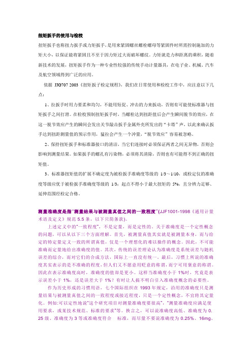
依据JJG707-2003《扭矩扳子检定规程》,我们在日常使用和检校工作中,应注意以下几点:1、拉扳手时用力要柔和均匀,不能用短促、冲击的力来扳动,否则有可能使标准器与扭矩扳手之间打滑。
在检校预制扭矩扳手时,当螺栓达到扭距值后会产生瞬间脱节的效应,在这一脱节效应产生的瞬间会发出关节敲击扳手金属外壳所发出的“卡塔”声,以此来确认扳手达到扭距测量值的预示作用,猛拉会产生一个冲量,“脱节效应”容易被忽略。
2、保持扭矩扳手和标准器接口的清洁,当它们连接时必须保证两者之间无异物,否则会影响到测量结果。
如果扳手的螺孔有污染物,必须将其清除,否则也有可能得不到正确的扭矩值。
3、标准器扭矩值的扩展不确定度为被检扳手准确度等级的1/3~1/10,或检定仪的准确度等级应优于被检扳手准确度等级的1/3;起点不得小于最大扭矩的5%,且分辨力足够、延伸范围经检定合格。
测量准确度是指“测量结果与被测量真值之间的一致程度”(JJF1001-1998《通用计量术语及定义》规范5.5条,以下只简条款)。
上述定义中的“一致程度”,不是定量,而是定性的。
关于准确度是一个定性概念的问题,可以从以下三个方面理解。
首先,被测量真值其实就是被测量本身,而与给定的特定量定义一致的所谓真值,仅是一个理想化的难以操作的概念。
因此,不可能准确而定量地给出准确度的值。
其次,传统的误差理论认为准确度是系统误差与随机误差的综合,而对它们的合成方法,国际上一直没有统一。
最后,习惯上所说的准确度其实表示的是不准确的程度,但人们又不愿意用贬意的称谓,而宁可用褒意的称谓。
因此在表示准确度高时,准确度的值却是更小。
扭力扳手操作指导书

扭力扳手操作指导书【产品名称:扭力扳手】操作指导书注意事项:1-本文档为扭力扳手操作指导书,旨在指导用户正确使用和维护扭力扳手。
2-在使用扭力扳手之前,请仔细阅读本指导书,并按照操作步骤进行实施。
3-若您在操作过程中遇到问题,请参考本指导书的故障排除部分,在解决问题后再次进行操作。
一、产品概述1-扭力扳手是一种专门用于调整和控制螺栓拧紧扭力的工具,广泛应用于机械制造、汽车维修等领域。
2-扭力扳手的主要组成部分包括手柄、扭力调节装置和扭力指示装置。
二、使用前准备1-仔细阅读产品说明书,了解产品的特点和性能要求。
2-检查扭力扳手的外观是否完好,有无明显损坏。
3-检查扭力扳手的扭力调节装置和扭力指示装置,确保其正常工作。
三、操作步骤1-确定需要拧紧的螺栓规格和扭力要求。
2-使用提供的螺栓拧紧力矩表,确定需要设置的扭力数值。
3-根据扭力数值,使用扭力调节装置调整扭力扳手的扭力大小。
4-将扭力扳手固定在需要拧紧的螺栓上。
5-用手握住扳手手柄,用适当的力量旋转手柄,直到扭力指示装置指示达到设定的扭力数值。
6-如果需要多次拧紧螺栓,请重复以上步骤。
四、维护保养1-每次使用后,用干净的布擦拭扭力扳手的表面,确保其干燥无尘。
2-检查扭力扳手的各个部件是否存在松动或损坏,如有问题请及时修理或更换。
3-定期对扭力扳手进行校准,以确保其扭力准确可靠。
4-在长时间不使用扭力扳手时,应存放在干燥、通风的地方,避免受潮或受热。
五、故障排除常见故障及解决方法:1-扭力扳手无法调节扭力:检查扭力调节装置是否损坏,如有损坏请更换。
2-扭力指示装置不准确:检查扭力指示装置是否松动或损坏,如有问题请修理或更换。
【附件】附件一:螺栓拧紧力矩表【法律名词及注释】1-扭力:物体周围绕轴线旋转的力矩。
2-扭力调节装置:用于调整扭力扳手的扭力大小的装置。
3-扭力指示装置:用于指示扭力扳手当前扭力数值的装置。
扭力扳手使用作业指导书

4
接触网连接螺栓紧固力矩标准
标准代号
名称
螺栓直径(MM)
紧固力矩(N*M)
TB2075.5-90
定位线夹
10
25
TB2075.6-90
铝定位线夹
10
25
TB2075.7-90
吊弦线夹
10
44
TB2075.13-90
长定位环
U螺栓M12
44
TB2075.14-90
套管双耳
U螺栓M16
70
TB2075.15-90
套管绞环
16
70
TB2075.16-90
杵座鞍子
U螺栓M10
25
TB2075.17-90
钩头鞍子
U螺栓M10
25
TB2075.18-90
定位环线夹
J螺栓M10
44
TB2075.19-90
22
98
TB2075.54-90
线锚角钢
22
98
TB2075.23-90
压管
M10/M12
25/44
TB2075.59-90
底座槽钢
底座U螺栓M16
59
TB2075.62-90来自特型拉杆底座底座U螺栓M16
59
TB2075.65-90
特型钢锚角钢
22
98
TB2075.455-90
软横跨固定角钢
16
70
④在使用期限内因使用管理不当造成扭矩扳手丢失的部门,按新工具价值的标准对责任人或责任班组进行全额扣罚。
力矩扳手使用说明书

Prepared by:- Mark DalleyHi-Force TWS-N series of lightweight aluminium hydraulic torque wrenches are designedto handle the toughest bolting jobs quickly and accurately. All models provide a torqueaccuracy of +/- 3%. The reaction arm allows the user to easily position the tool and ifnecessary react off the tool body in confined situations.SAFETYREAD THIS MANUAL BEFORE OPERATING THE TOOLFAILURE TO OBSERVE THE FOLLOWING WARNINGS COULDRESULT IN SERIOUS BODILY INJURY∙Always operate, inspect and maintain this tool in accordance with International Standards ISO9001 and ANSI B30.1.∙This tool will function using an air or electric powered hydraulic pump. Adhere to the pump safety requirements and follow instructions when connecting the pump tothe tool.∙Use only equipment rated for the same pressure and torque.∙Use only a hydraulic pump capable of generating 10,000 psig (700Bar) maximum pressure with this tool.∙Use only twin line hydraulic hose rated for 10,000 psig (700Bar) pressure with this tool.∙Do not interchange the male and female swivel inlets on the tool or theconnections on one end of the hose. Reversing the inlets will reverse the powerstroke cycle and may damage the tool.∙Do not use damaged, frayed or deteriorated hoses and fittings. Make certain there are no cracks, splits or leaks in the hoses.∙Use the quick connects system to attach the hoses to the tool and pump. Make certain the spring-loaded retaining rings are fully engaged to prevent theconnectors from disengaging under pressure.∙When connecting hoses that have not been preloaded with hydraulic oil, make certain the pump reservoir is not drained of oil during start-up.∙Do not remove any labels. Replace any damaged label.Prepared by:- Mark DalleyUSING THE TOOL∙Do not handle pressurised hoses. Escaping oil under pressure can penetrate the skin, causing serious injury. If oil is injected under the skin, see a doctor immediately.∙Never pressurise uncoupled couplers. Only use hydraulic equipment in a coupled system.∙Always wear eye and ear protection when operating or performing maintenance of this tool.∙Always wear head and hand protection and protective clothing when operating this tool.∙Use accessories recommended by Hi-Force.∙Use only impact sockets and accessories. Do not use hand (chrome) sockets or accessories.∙Use only sockets and accesssories that correctly fit the bolt or nut and function without tilting the tool off the axis of the bolt.∙This tool is not designed for working in explosive atmospheres.∙This tool is not insulated against electric shock. When using this tool with a pump having an electrical power source or circuits, follow the pump instructions forproper grounding.∙Do not carry or lift the tool by the hose.CONNECTING THE TOOLAttach the twin line hose to the uni-swivel coupling of the Square Drive Torque Wrench using the spring–loaded quick connect ends. Make certain that they are fully engaged.Connect the opposite ends of the hose to the Pump in the same manner.Prepared by:- Mark DalleySETTING THE SQUARE DRIVE FOR ROTATIONThe position of the Square Drive when looking toward the Shroud will determine if the tool is set to tighten or loosen the nut. When the Square Drive extends to the left when looking at the Shroud from the front, the tool is set to loosen the nut. When the Square Drive extends to the right, the tool is set to tighten the nut. To change the direction of rotation press the push button release on the drive retaining plate and pull the Square Drive out of the Housing. Insert the Square Drive into the opposite side of the Housing and secure it by installing the push button release retaining plate into the end of the drive.SETTING THE TORQUEAfter determining the desired torque, use the torque conversion chart on the Shroud or the torque conversion charts on page 5 to determine the pressure that is necessary to achieve that torque.1. Connect the tool to the power supply and turn the pump on.2. Depress the advance remote control button causing the pressure to be shown on thegauge.3. Adjust the pressure by first loosening the nut that locks the pressure adjustment handleand then rotate the handle clockwise to increase the pressure and counter clockwise to decrease the pressure. When decreasing pressure, always lower the pressure below the desired point and then bring the pressure gauge back up to the desired pressure.4. When the desired pressure is reached, retighten the lock nut and cycle the tool again toconfirm that the desired pressure setting has been obtained.Prepared by:- Mark DalleySETTING THE REACTION ARMThe function of a reaction device is to hold the tool in position against the forces generated to tighten or loosen bolts or nuts. Hydraulic wrenches generate tremendous force.Make sure the Reaction Arm is positioned correctly. (Refer to DRAWING 1).The Reaction Arm can be positioned in numerous places within a 360O circle. However, for the Arm to be correctly positioned, it must be set within a 90O quadrant of that circle.That quadrant is the area located between the protruding Square Drive and the bottom of the Housing away from the Swivel Inlets. It will always be toward the lower half of the Housing and on one side of the Housing when tightening and the other side when loosening.PLEASE NOTE: Under certain conditions it is possible for the reaction arm location plug to be pushed slightly into the tool body. This can happen as a result of the tool beingdropped or hit against a solid object while the arm is not fitted. Once this has occurred the reaction arm may not latch into place correctly.The problem is very simply cured and in many cases will rectify itself before the operator is even aware it has occurred. To return the plug to its correct position simply connect the tool to a pump and cycle the mechanism backwards and forwards a couple of times. In a lot of cases just switching the pump on will be enough. The reaction arm should then latch on correctly.OPERATING THE WRENCH (Refer to DRAWING 2)The position of the Square Drive relative to the Shroud determines whether the action will tighten or loosen the nut. The power stroke of the Piston Assembly will always turn the Square Drive toward the Shroud.WRENCH POSITIONS1. Place the Square Drive in the socket, insert the socket retainer ring and pin, and placethe socket on the nut. Make certain the Square Drive and socket are the correct size for the nut and that the socket fully engages the nut2. Position the reaction arm against an adjacent nut, flange or solid system component.Make certain that there is clearance for the hoses and uni-swivel coupling. DO NOT allow the tool to react against the hoses, or uni-swivel coupling. When reacting directly off the tool body i.e., with reaction arm removed DO NOT react off the exposed End Plug Spigot.Prepared by:- Mark Dalley3. After having turned the Pump on and pre-setting the pressure for the correct torque,depress the remote control advance button to advance the Piston Assembly.4. When the wrench is started, the reaction surface of the wrench or Reaction Arm willmove against the contact point and the nut will begin to turn. Once the piston reaches the end of its stroke depress the remote control return button to retract the piston.5. Continue this cycling operation of advance and retract until the nut is no longer turningand the Pump Gauge reaches the pre-set pressure. The piston rod will retract when the retract button is pressed and under normal conditions, an audible “click” will be heard as the tool resets itself.6. Continue to cycle the tool until it “stalls” and the pre-set psi/torque has been attained.7. Once the nut stops rotating, cycle the tool one last time to achieve total torque.DRAWING 1DRAWING 2`Prepared by:- Mark DalleyEXTENDED REACTION ARM (Refer to DRAWING 3)The extended reaction arm can only be positioned in one orientation i.e. the flat of the reaction contact point to be 90° to the side of the torque wrench body.PLEASE NOTE: The extended reaction arm is purchased separately as an accessory.For further information please contact your nearest Hi-Force distributor. DRAWING 3LUBRICATIONMarine Grade Moly LubeLubrication frequency is dependent on factors known only to the user. The amount of contaminants in the work area is one factor. Tools used in a clean room environment will obviously require less service than a tool used out-doors and dropped in loose dirt or sand. Marine Grade Moly Lube is formulated not to wash out of the tool in areas where lubrication is critical. Whenever lubrication is required, lubricate as follows:1. Remove the Drive Plate, Ratchet, Segment Pawl and Drive Sleeves and wash the components in a suitable cleaning solution in a well –ventilated area.2. After drying the components, wipe a film of Moly Lube (Marine Grade) onto the wear surface of both Drive Sleeves and the ends of the Ratchet.3. Spread a light film of Moly Lube (Marine Grade) onto the inner face and both sides of the Drive Plate.Do not pack the teeth of the Segment Pawl or Ratchet with lube. It can prevent the teeth from engaging properly.Prepared by:- Mark DalleyPage 7 of 12Prepared by:- Mark DalleyPrepared by:- Mark Dalley NOTE(S):-Prepared by:- Mark Dalley NOTE(S):-Prepared by:- Mark Dalley NOTE(S):-Prepared by:- Mark Dalley。
力矩扳手

第三节力矩扳手的使用与管理
1 力矩扳手的种类。
1.1 可调型力矩扳手见图1(QL型)。
用于力矩值和紧固螺栓尺寸发生变化或希望使用棘轮紧固作业的场合使用。
1.2 定力矩型扳手见图2(SP型)。
用于具有固定尺寸的螺母、螺栓的紧固作业,作为专用扳手使用,
紧固时按紧固方向使用,不允许反向使用。
2 操作要领
2.1 力矩扳手与被紧固的物体应平行紧固。
2.2 预紧固时可用棘轮式扳手快速地进行。
但在最终紧固时,则用力
矩扳手。
2.3 可调型、定力矩型扳手在紧固力矩达到规定数值会发出咯嚓一声,
此时表示紧固完毕,不要回松。
3 力矩扳手的管理
3.1 使用车间应有专人负责保管、保养。
3.2 由装配车间负责,进行每月一次的一般外观、机械性能检查。
3.3 由计量处和装配车间负责进行每年两次的力矩扳手力矩值的计量校验。
对于不合格的力矩扳手,装配中严禁使用。
数显套筒力矩扳手的参数介绍

数显套筒力矩扳手的参数介绍数显套筒力矩扳手是一种广泛应用于现代工业制造的工具,它可以准确地测量和控制螺纹连接器的扭矩。
本文将介绍数显套筒力矩扳手的参数,帮助读者更好地了解这种工具的性能和适用范围。
1. 切换单位数显套筒力矩扳手通常可以在不同的扭矩单位之间切换,根据应用需要选择最适合的单位。
例如,扭矩可以用N·m、ft·lb或in·lb等单位表示。
在使用数显套筒力矩扳手之前,操作人员需要确保选择了正确的单位并进行合适的校准。
2. 测量范围每个数显套筒力矩扳手都有一个测量范围,通常从较小的扭矩值开始,到高扭矩值结束。
测量范围是指扭矩扳手可以准确地测量的最小和最大扭矩值。
选择正确的测量范围很重要,因为使用超出扳手最大范围的扭矩可能导致扳手损坏或不准确。
3. 精度数显套筒力矩扳手的精度是指它可以测量扭矩的准确度。
精度通常以百分比表示,例如,精度为±2%表示测量值的误差不超过设定值的2%。
精度越高,扭矩测量就更加准确。
因此,在购买数显套筒力矩扳手时,应该优先选择精度更高的产品。
4. 分辨率分辨率是数显套筒力矩扳手能够检测到和显示的最小增量。
分辨率越高,扭矩测量的精度就越高。
例如,分辨率为0.1N·m表示扳手可以检测到0.1N·m扭矩增量,并将其显示在数码显示器上。
5. 最大误差最大误差是数显套筒力矩扳手可以产生的最大误差。
误差是因为:硬件误差,软件误差,环境误差四个部分组成。
选择时应该注意,最大误差越小,扭矩测量就越准确。
6. 适用范围不同品牌的数显套筒力矩扳手有不同的适用范围。
适用范围包括可靠性、使用寿命、测量环境、工作温度范围等等,用户应该根据应用场景选择相应适用范围的扭矩扳手。
此外,数显套筒力矩扳手还有防滑机械结构、抗冲击等保护设计,可应用于各种复杂的工作环境。
数显套筒力矩扳手是一种可以帮助工业生产提高效率的工具,适用于多种场景。
了解数显套筒力矩扳手的参数将有助于用户更好地选择和使用这种工具。
- 1、下载文档前请自行甄别文档内容的完整性,平台不提供额外的编辑、内容补充、找答案等附加服务。
- 2、"仅部分预览"的文档,不可在线预览部分如存在完整性等问题,可反馈申请退款(可完整预览的文档不适用该条件!)。
- 3、如文档侵犯您的权益,请联系客服反馈,我们会尽快为您处理(人工客服工作时间:9:00-18:30)。
力矩扳手的使用说明
一、力矩扳手的使用方法与注意事项
钢筋连接力矩扳手主要用于直螺纹钢筋连接套筒连接合格值的测定,该扳手示值误差小,重复精度高,使用、标定、维修方便,是钢筋直螺纹接头施工的必备工具。
一、使用方法:
1、适用范围:该产品适用于扭矩范围为20-100Nm力矩值的测试。
2、技术指标:示值日误差/示值重复误差小于等于0.5%,扳手力臂长度 600mm,扭矩值设定范围 70~370N.M。
3、操作方法:(1)预置扭矩,旋转手柄,刻度盘即随之转动,当需要的刻度值与视镜上的红线对正后,停止转动手柄,并将后盖按箭头方向转动到位,使手柄不能再转动,锁定扭矩。
(2)施力,按要求预置好扭矩后,用扭力扳手套住阀杆,按“↓”方向缓慢施加作用力,当听到扳手发出“哒”的声响或有明显手感时,阀门已关闭,本次作业完成,应停止用力,扳手随即自动复位。
4、调整扳手精度办法:用专用钥匙插入尾部端面孔内,顺时针旋转增大力矩值,逆时针旋转减少力矩值。
5、标定根据《力矩扳手》(JJG770-2003)第6.4条规定:“力矩扳手的检测周期不超过一年”。
二、注意事项:
1、注意防水、泥、沙等杂物进入扳手手柄内,严禁将力矩扳手当锤子使用,不得超扭矩使用;
2 、使用时扳手钳头要端平,加力要均匀,不得用力过猛或施加冲击力。
扳手只能按“↓”方向施力;
3 、当听到力矩扳手发出“咔嚓”的声响时,要立刻停止扳动扳手,以免造成扳手测力部分的损坏。
4、扳手长期不适用时,应将扳手刻度值设置在零位上,以免测力原件疲劳失准。
5、扳手严禁在设置位为零时使用,因为在此状态下加力无声响信号发出,容易过载损坏扳手。
6 、使用过程中,若扳手无响信号发出时,应立即停止使用,进行维修。
维修后的扳手需标定,标定合格后方可使用。
二、扭力扳手的使用方法及选型
(1)所选用的扭力扳手的开口尺寸必须与螺栓或螺母的尺寸相符合,扳手开口过大易滑脱并损伤螺件的六角,在进口汽车维修中,应注意扳手公英制的选择;各类扳手的选用原则,一般优先选用套筒扳手,其次为梅花扳手,再次为开口扳手,最后选活动扳手。
(2)为防止扳手损坏和滑脱,应使拉力作用在开口较厚的一边,这一点对受力较大的活动扳手尤其应该注意,以防开口出现“八”字形,损坏螺母和扳手。
(3)扭力扳手是按人手的力量来设计的`,遇到较紧的螺纹件时,不能用锤击打扳手;除套筒扳手外,其它扳手都不能套装加力杆,以防损坏扳手或螺纹连接件(4)扭力扳手使用时,当听到“啪”的一声时,此时是最合适的
注:
1.用途:扭力扳手为旋转螺栓或螺帽的工具。
2.用法:扭力扳手扳转时应该使用拉力,推转扳手极易发生危险。
3.扭力扳可用于松紧螺栓,螺栓旋紧前应先将螺栓清洁并上润滑油。
4.使用扭力扳手旋紧螺栓时应均匀使力,不得利用冲击力。
三、预置式扭力扳手特点
1、具有预设扭矩数值和声响装置。
当紧固件的拧紧扭矩达到预设数值时,能自动发出讯号“卡嗒”(click)的一声,同时伴有明显的手感振动,提示完成工作。
解除作用力后,扳手各相关零件能自动复位。
2、可切换二种方向。
拨转棘轮转向开关,扳手可逆时针加力。
3、公、英制(N.m、lbf.ft)双刻度线;手柄微分刻度线。
读数清晰、准确。
4、合金钢材料锻制,坚固耐用,寿命长。
校准追溯至美国国家技术标准学会(NBS)。
5、精确度符合ISO6789:1992.ASMEB107.14,GGG-W-686.±4%。
