机械外文翻译
常用研磨机外文文献翻译、中英文翻译、外文翻译
常用研磨机外文文献翻译、中英文翻译、外文翻译Grinding machine is a crucial n processing method that offers high machining accuracy and can process a wide range of materials。
It is suitable for almost all kinds of material processing。
and can achieve very high n and shape accuracy。
even reaching the limit。
The machining accuracy of grinding device is simple and does not require complex ___.2.Types of Grinding MachinesGrinding machines are mainly used for n grinding of workpiece planes。
cylindrical workpiece surfaces (both inside and outside)。
tapered faces inside。
spheres。
thread faces。
and other types of ___ grinding machines。
including disc-type grinding machines。
shaft-type grinding machines。
ic grinding machines。
and special grinding machines.3.Disc-type Grinding MachineThe disc-type grinding machine is a type of grinding machine that uses a grinding disc to grind the ___。
不锈钢钢材机械外文文献翻译、中英文翻译、外文翻译

外文原文:Stainless SteelPetro-chemical industry with its own production of some of the features, such as its operating temperature range, low-temperature conditions up to -196 ℃, temperatures can reach more than 500 ℃; operating pressure there is external pressure, vacuum, atmospheric pressure, medium pressure, high pressure, ultra-high pressure (more than 100MPa); In addition, the operating environment in the medium complexity, such as the existence of corrosion, wear and tear, and flammable, explosive, toxic and other solid, gaseous, liquid and a variety of mixed media chloride, sulfide and other salt category. Therefore, the petrochemical industry in the use of stainless steel, the requirements of stainless steel has strong corrosion resistance, including anti-chloride, sulfide and other corrosive salts; resistant to high temperature and low temperature performance. Among them, the petrochemical plant at 500 ~ 600 ℃, the equipment and pipe materials in general to choose a variety of austenitic stainless steel-based, such as 304H, 316,321, such as austenitic stainless steel has been widely used; and for oil exploration, the development of the field of stainless steel with anti-called carbon dioxide, hydrogen sulfide corrosion properties. At present, China's crude oil exploration, development is mainly used in 3Cr, 9Cr, 13Cr, super 13Cr and containing more than Cr22 stainless steel thick-walled, non-magnetic drill collar and drill pipe.At present, China's petrochemical industry in the stainless steel variety of choice, in general to 304 mainly, steel plate thickness of 6 to 22 millimeters, the main polymer used in the construction of storage tanks, heat exchanger shell. In addition, some pieces of the use of reactor tower 316L, TP347, etc., the thickness of 2 ~ 6 mm. Glacial acetic acid and liquid delivery vehicles (train tanker) General use of 304 and 306 plate. In addition, production of the device because of the existence of urea carbamate amine condensate, a highly corrosive, generally stripper, separation, and the use of 316L stainless steel condenser. On the stainless steel clad plate, such plate mainly used in oil refining equipment reaction tower, commonly used for 20R +0 Cr13AL, 16MnR +0 Cr13AL, 20R +0 Cr13 such. Due to the substrate, rehabilitation materials and productionmethods, equipment limitations, domestic composite steel plate thickness, length far from being able to fully meet the demands of the petrochemical industry. In addition, the domestic stainless steel plate splicing, heat treatment, testing and other means yet to be improved.As a result of a wide range of stainless steel, petrochemical industry, currently used for the type of austenitic stainless steel, of which 304 brands of stainless steel plate, tube forgings largest amount, 316,304 L, 316L of the plate, tube, forging a larger amount, ASTM standard TP321, TP347, TP316 brands of boiler tubes, heat exchanger is also gradually increasing dosage. In addition, a special two-way stainless steel as a result of corrosion resistance, Chiang Kai-shek in the petrochemical industry has been rapid promotion and use, of which two-way gradually increasing the amount of stainless steel tubes. At present, China's petrochemical industry in the use of stainless steel is about 70,000 tons, of which stainless steel plate (8 mm or more) the amount of approximately 10,000 tons, stainless steel composite plate is about 15,000 tons, stainless steel seamless steel tube is about 40,000 tons , stainless steel pipe is about5000 tons.Domestic stainless steel in the petrochemical field of application of thereasons for not widespreadAt present, the domestic stainless steel in the petrochemical field of application is not extensive, mainly in the following reasons: First, do not support the issue of standards. China's petrochemical industry has been formed to meet the development needs of the standard system; at home and abroad for high-pressure, high-sulfur, carbon dioxide high "three high" natural gas production equipment, material smelting, manufacturing, testing, testing technology subsidiary norms and standards is still incomplete. Second, product problems. In this regard, mainly stainless steel plate, tube, forging, welding material is not matching. Third, the issue size. Domestic metallurgical industry needs of the petrochemical industry in the thick wide board, large-diameter, thick-walled steel pipe production capacity is very limited. Fourth, quality issues, product qualitystainless steel tube instability. Fifth, research and development problems. New varieties of the domestic stainless steel R & D and production is still unable to meet the petrochemical industry's development needs. Inaddition, the stainless steel research, production and exchange of information between users of the existence of the problem poor. As a result of these factors, the need for stainless steel and petrochemical industries there are many varieties of domestic enterprises can not provide, such as four meters wide of the heavy plate production in China is not yet, there are many forms of stainless steel equipment is imported. In addition, domestic enterprises in product development with foreign enterprises is still lagging behind compared to, for example, some steel companies in Europe every year to launch a dozen new varieties of stainless steel, and Chinese enterprises in this respect, the work is notenough.The five major trends in the petrochemical proposed new requirementsfor stainless steelThe future of China's petrochemical industry will move towards the top five trends in the development of stainless steel products and higherrequirements. First of all, the future of China's oil and gas field exploration and development efforts will further increase. Such as carbon dioxide will be injected back underground ways to reduce carbon dioxide emissions and improve the oil recovery rate. At the same time, China's natural gas exploration and development efforts will be greater than the crude oil exploration and development, and to the high sulfur content, carbon dioxide area development (16% hydrogen sulfide content, carbon dioxide content of about 8%), and will further deepen the depth of wells, land Sham Tseng will exceed the 8000 meters. Second, the petrochemical plant will be large scale. Ethylene production of single device will exceed one million tons; refining single factory refining capacity more than 15 million tons; of purified terephthalic acid (PTA) production capacity of a single plant more than 800,000 tons; stainless steel tanks to the large-scale development. The third is run petrochemical plant will be a long-term development, and gradually overhaul the current cycle of thetransition to 3 years. Fourth, the petrochemical production will diversify the source of materials development. With the improvement of the requirements of environmental protection and energy consumption structure, using natural gas as raw materials of chemical industry is developing rapidly. As a result of natural gas at minus 160 ℃ can be achieved under the conditions of liquefaction, so the need for stainless steel storage and transportation equipment. In addition, as China's LNG imports increase in coastal areas need to receive large-scale construction, working capital and storage facilities, can be expected in this regard will be very large stainless steel consumption.These petrochemical industry development trend of stainless steel products, specifications and varieties have put forward new demands. From anti-corrosion requirements, the petrochemical industry production device temperature, pressure, media are major changes have taken place, stainless steel used in a more harsh environment, anti-corrosion performance by a single change to the composite performance. In the processing performance, the requirements of stainless steel a higher intensity, better toughness, weldability and good processability. In geometry, the requirements of stainless steel products and high precision, width increased, large-diameter steel pipe, steel pipe wall thickness increased. In the standards, stainless steel production as soon as possible with international standards. In addition, the petrochemical industry as a result of each of wells, each set of conditions of service refining device there is a difference, related stainless steel production enterprises should be based on the actual situation in the provision of personalized services. In addition, with the increased usage of stainless steel, stainless steel used in economics is even more important. Therefore, the domestic iron and steel enterprises, especially the steel pipe industry should improve the technological content of products and value-added, high-end product market occupation. At present, many European steel is no longer the production of low value-added oil well pipes, and will focus entirely on high added-tube, the preparation for these high-end products occupied theChinese market. (FocusRecently, China Special Steel Enterprises stainless steel branch of Li Cheng, executive president of the stainless steel industry in talking about China's problems in the development pointed out that the stainless steel to replace imports from the side, although capacity has been able to achieve self-sufficiency, but in fact only part of to replace imports, it is necessary to fully or largely replaced by imports, but also depends on our variety and quality products can meet the various requirements. He also pointed out that the market of fake and shoddy products that seriously endangers the users of stainless steel, it is proposed to increase the relevantdepartments the crackdown.Said Li Cheng, China's stainless steel production capacity from the already self-sufficiency can be achieved, but only a partial substitute for imports. Common market of the four most common grades, namely, 316 and 304 Austenitic. Ferrite 409 and 430, including 304 in the world, accounting for 50 percent of consumption, the use of nearly a hundred years of history. But it is not a single species to the new production of the 304 as an example, in order to meet the varying demands of customers, they will have a brand dozens of varieties, the same as a result of the 304 different varieties in the market price per ton can also be a difference of several hundred dollars to a thousand dollars, we can see the value of a good product, there are markets. This value needs to be done can be. 430 the past two years has developed very rapidly, in fact, this is an in production is not easy to master the varieties, r value of the performance of stamping a crease resistance, it is difficult to achieve, and now the world's more advanced r ≥ 1.2, At a time when there was virtually no punching fold, China and some production plants in both there are still some problems; 409 brands, it seems easier to see the production of components, but it's forming, and welding of the automobile industry to meet the requirements of the development will not be easy.In recent years, the development of China's manufacturing of stainless steel materials for many new requirements, such as power generation, petrochemical, and automobile industries are faced with the newrequirements of the material. Power generation systems need a lot of supercritical required stainless steel pipe, China is now still can not produce, the number of heat exchanger tubes we find it difficult to adapt, petrochemical development needs of some special stainless steel We are also in the trial. Automobile manufacturing, a number of special varieties of high-quality stainless steel requirements, we simply have not yet produced. To meet the needs of users and the use of the industry is necessary to combine joint research, innovation through research in order to solve the problem. In short, we can not just the manufacturingenterprises in the advanced hardware, we are in process technology, smelting technology and the development of both species have a larger gap, attracted the greatest attention to and constantly strive to improve.China's stainless steel market is facing a prominent issue is that the market is flooded with fake and shoddy products. In this regard, Li Cheng pointed out that in recent years because of soaring nickel prices do not appear in accordance with international and domestic standards of the low production of low nickel chromium high manganese so-called "200"series of steel, poor corrosion resistance, in which steel Based on the more serious occurred, the evolution of the market is now known as the "double-free steel" of inferior goods. The so-called double-free is no nickel, non-magnetic, this so-called "double-free" Steel does not have the non-rust and corrosion-resistant properties, which cause great harm to the user at the same time, for the jerry-built illegal producers and sellers the opportunity to bring huge profits, a very serious problem. Another is the emergence of stainless steel decorative tube size and thickness specifications for the production of non-serious "shrink", does not have the necessary stiffness of stainless steel tubes, so all kinds of deception users, to the credibility of stainless steel brought the crisis.At present the country is building a number of major projects, such as the Beijing Olympics and Shanghai World Expo project works, if only to keep the prices down in the tender, it will naturally arise in a cheap fake and shoddy products. Therefore, he called on the community especially the construction of the developers, must be quality-oriented, to avoid allkinds of hidden dangers and accidents to avoid failure and lead to very serious consequences as a result of the material. We should be treated in good faith users of harm to reputation and the interests of consumers of stainless steel act. Suggested that the state departments intensify thecrackdown.Development history::The invention of stainless steel is the world's metallurgical history of a significant achievement. The early 20th century, khazrajiya (LBGuillet) in 1904 -1906 and Porter million (AMPortevin) in 1909-1911 in France; Giessen (W. Giesen) in the years 1907-1909, respectively, in the United Kingdom found Fe - Cr and Fe-Cr-Ni alloy resistance to corrosion.蒙纳尔茨(P. Monnartz) in 1908-1911 in Germany put forward a theory of stainless steel and passivation of the many viewpoints.The inventor of stainless steel for industrial use are: Brearley (H. Brearly) 1912-1913 was developed in the United Kingdom with Cr12% -13% of the martensitic stainless steel; Dan Qi Zeng (C. Dantsizen) 1911-1914 in The United States has developed with Cr14% -16%, C0.07% -0.15% of ferritic stainless steel; Maurer (E. Maurer) and Strauss (B. Strauss) 1912-1914 was developed in Germany with C <1%, Cr15% -40%, Ni <20% of austenitic stainless steel. In 1929, Strauss (B. Strauss) made of low carbon 18-8 (Cr-18%, Ni-8%) stainless steel patent.In order to solve 18-8 steel sensitized state Intergranular corrosion, in1931 Germany's Huo译文:不锈钢石油化工行业生产具有自身的一些特点,例如其操作温度范围宽,低温条件时可达-196℃,高温时可达500℃以上;操作压力有外压、真空、常压、中压、高压、超高压(大于100MPa);此外,操作环境中介质复杂,如存在腐蚀性、磨损性、易燃、易爆、有毒等固态、气态、液态以及各种混合介质氯化物、硫化物和其他盐类。
(完整word版)机械外文翻译外文文献英文文献一个复杂纸盒的包装机器人
附件1:外文资料翻译译文一个复杂纸盒的包装机器人Venketesh N。
Dubey英国设计学院,工程和计算机,伯恩茅斯大学,普尔Jian S。
Dai伦敦大学国王学院,英国伦敦大学,伦敦摘要目的—为了展示设计一种可以折叠复杂几何形状的纸盒的多功能包装机的可行性。
设计/方法/方式—这项研究对各种几何形状的纸盒进行研究,将纸盒分为适当的类型以及机器可以实现的操作;把能加工这些纸盒,并进行机械建模和仿真,且最终可以设计和开发的包装机概念化。
研究结果-这种多功能包装机已经被证明是可能的。
只需将这种多功能包装机小型化,并对它投资以促进其发展,这种机器可以成为现实。
研究限制因素/问题-本研究的目的是证明这种包装机的原理,但实际应用需要考虑结合传感器给出了一个紧凑的、便携式系统。
创意/价值—这项设计是独一无二的,并已被证明可以折叠各种复杂形状的纸盒。
关键字:机器人技术包装自动化文章类型:研究论文1 简介产品包装是关键的工业领域之一,以自动化为首要权益.任何产品流通到消费者手中需要某种形式的包装,无论是食品、礼品或医疗用品。
因此,对高速的产品包装有持续的需求。
对于周期性消费品和精美礼品,这项需求更是大大增加.它们要求包装设计新颖且有吸引力,以吸引潜在客户。
通常这类产品用外观精美、形状复杂的纸盒递送。
如果采用手工方法进行包装,不仅令工人感到乏味且操作复杂,也费时和单调。
对于简单的纸盒包装,通过使用沿传送带布置的专用机器,已经获得了实现。
这些机器只能处理固定类型的纸盒,任何形状和结构的变化很难纳入到系统之中。
在大多数情况下,它们需要进行超过40种变化以适应同种类型但大小不同的纸盒,这就意味着每一个特定类型的纸盒需要一条包装生产线。
从一种类型到另一种类型的纸盒折叠组装生产线的转换将会使资本支出增加。
因为这些限制因素和转换生产线的相关成本,包装的灵活性将会失去。
因此,作为一种补充,手工生产线被引进以适应不同类型的纸盒的生产,从而解决转换生产线的问题.它们承担了大约10%的工作订单,并被用作生产促销产品的组装生产线.但是,问题仍然存在,手工生产线上的管理员和操作工需要一个长时间的学习过程,而且与机器生产线不同,劳动伤害主要是源于扭手动作.此外,手工生产线通常被认为是一个季节性的生产力,仍然需要专门的机器长年运行,以节约成本和时间。
机械毕业设计英文外文翻译402驱动桥和差速器 (2)

附录附录ADrive axle/differentialAll vehicles have some type of drive axle/differential assembly incorporated into the driveline. Whether it is front, rear or four wheel drive, differentials are necessary for the smooth application of engine power to the road.PowerflowThe drive axle must transmit power through a 90° angle. The flow of power in conventional front engine/rear wheel drive vehicles moves from the engine to the drive axle in approximately a straight line. However, at the drive axle, the power must be turned at right angles (from the line of the driveshaft) and directed to the drive wheels.This is accomplished by a pinion drive gear, which turns a circular ring gear. The ring gear is attached to a differential housing, containing a set of smaller gears that are splined to the inner end of each axle shaft. As the housing is rotated, the internal differential gears turn the axle shafts, which are also attached to the drive wheels.Fig 1 Drive axleRear-wheel driveRear-wheel-drive vehicles are mostly trucks, very large sedans and many sports car and coupe models. The typical rear wheel drive vehicle uses a front mounted engine and transmission assemblies with a driveshaft coupling the transmission to the rear drive axle. Drive in through the layout of the bridge, the bridge drive shaft arranged vertically in the same vertical plane, and not the drive axle shaft, respectively, in their own sub-actuator with a direct connection, but the actuator is located at the front or the back of the adjacent shaftof the two bridges is arranged in series. Vehicle before and after the two ends of the driving force of the drive axle, is the sub-actuator and the transmission through the middle of the bridge. The advantage is not onlya reduction of the number of drive shaft, and raise the driving axle of the common parts of each other, and to simplify the structure, reduces the volume and quality.Fig 2 Rear-wheel-drive axleSome vehicles do not follow this typical example. Such as the older Porsche or Volkswagen vehicles which were rear engine, rear drive. These vehicles use a rear mounted transaxle with halfshafts connected to the drive wheels. Also, some vehicles were produced with a front engine, rear transaxle setup with a driveshaft connecting the engine to the transaxle, and halfshafts linking the transaxle to the drive wheels.Differential operationIn order to remove the wheel around in the kinematics due to the lack of co-ordination about the wheel diameter arising from a different or the same rolling radius of wheel travel required, inter-wheel motor vehicles are equipped with about differential, the latter to ensure that the car driver Bridge on both sides of the wheel when in range with a trip to the characteristics of rotating at different speeds to meet the requirements of the vehicle kinematics.Fig 3 Principle of differentialThe accompanying illustration has been provided to help understand how this occurs.1.The drive pinion, which is turned by the driveshaft, turns the ring gear.2.The ring gear, which is attached to the differential case, turns the case.3.The pinion shaft, located in a bore in the differential case, is at right angles to the axle shafts and turns with the case.4.The differential pinion (drive) gears are mounted on the pinion shaft and rotate with the shaft .5.Differential side gears (driven gears) are meshed with the pinion gears and turn with the differential housing and ring gear as a unit.6.The side gears are splined to the inner ends of the axle shafts and rotate the shafts as the housing turns.7.When both wheels have equal traction, the pinion gears do not rotate on the pinion shaft, since the input force of the pinion gears is divided equally between the two side gears.8.When it is necessary to turn a corner, the differential gearing becomes effective and allows the axle shafts to rotate at different speeds .Open-wheel differential on each general use the same amount of torque. To determine the size of the wheel torque to bear two factors:equipment and friction. In dry conditions, when a lot of friction, the wheel bearing torque by engine size and gear restrictions are hours in the friction (such as driving on ice), is restricted to a maximum torque, so that vehicles will not spin round. So even if the car can produce more torque, but also need to have sufficient traction to transfer torque to the ground. If you increase the throttle after the wheels slip, it will only make the wheels spin faster.Fig 4 Conventional differential Limited-slip and locking differential operationFig 5 Limited-slip differentialDifferential settlement of a car in the uneven road surface and steeringwheel-driven speed at about the different requirements; but is followed by the existence of differential in the side car wheel skid can not be effective when the power transmission, that is, the wheel slip can not produce the driving force, rather than spin the wheel and does not have enough torque. Good non-slip differential settlement of the car wheels skid on the side of the power transmission when the issue, that is, locking differential, so that no longer serve a useful differential right and left sides of the wheel can be the same torque.Limited-slip and locking differential operation can be divided into two major categories:(1) mandatory locking type in ordinary differential locking enforcement agencies to increase, when the side of the wheel skid occurs, the driver can be electric, pneumatic or mechanical means to manipulate the locking body meshing sets of DIP Shell will be with the axle differential lock into one, thus the temporary loss of differential role. Relatively simple structure in this way, but it must be operated by the driver, and good roads to stop locking and restore the role of differential.(2) self-locking differential installed in the oil viscosity or friction clutch coupling, when the side of the wheel skid occurs when both sides of the axle speed difference there, coupling or clutch friction resistance on the automatic, to make certain the other side of the wheel drive torque and the car continued to travel. When there is no speed difference on both sides of the wheel, the frictional resistance disappeared, the role of automatic restoration of differentials. More complicated structure in this way, but do not require drivers to operate. Has been increasingly applied in the car. About non-slip differential, notonly used for the differential between the wheels, but also for all-wheel drive vehicle inter-axle differential/.Gear ratioThe drive axle of a vehicle is said to have a certain axle ratio. This number (usually a whole number and a decimal fraction) is actually a comparison of the number of gear teeth on the ring gear and the pinion gear. For example, a 4.11 rear means that theoretically, there are 4.11 teeth on the ring gear for each tooth on the pinion gear or, put another way, the driveshaft must turn 4.11 times to turn the wheels once. The role of the final drive is to reduce the speed from the drive shaft, thereby increasing the torque. Lord of the reduction ratio reducer, a driving force for car performance and fuel economy have a greater impact. In general, the more reduction ratio the greater the acceleration and climbing ability, and relatively poor fuel economy. However, if it is too large, it can not play the full power of the engine to achieve the proper speed. The main reduction ratio is more Smaller ,the speed is higher, fuel economy is better, but the acceleration and climbing ability will be poor.附录B驱动桥和差速器所有的汽车都装有不同类型的驱动桥和差速器来驱动汽车行驶。
3D打印机外文文献翻译、中英文翻译、机械类外文翻译

3D打印机3D打印技术(英语:3Dprinting),即快速成形技术的一种,它是一种数字模型文件为基础,运用粉末状金属或塑料等可粘合材料,通过逐层打印的方式来构造物体的技术。
过去其常在模具制造、工业设计等领域被用于制造模型,现正逐渐用于一些产品的直接制造。
特别是一些高价值应用(比如髋关节或牙齿,或一些飞机零部件)已经有使用这种技术打印而成的零部件。
“3D打印技术”意味着这项技术的普及。
3D打印技术出现在上世纪90年代中期,实际上是利用光固化和纸层叠等技术的快速成型装置。
它与普通打印机工作原理基本相同,打印机内装有液体或粉末等“印材料”,与电脑连接后,通过电脑控制把“打印材料”一层层叠加起来,最终把计算机上的蓝图变成实物。
这一技术如今在多个领域得到应用,人们用它来制造服装、建筑模型、汽车、巧克力甜品等。
3D打印技术最突出的优点是无需机械加工或任何模具,就能直接从计算机图形数据中生成任何形状的零件,从而极大地缩短产品的研制周期,提高生产率和降低生产成本。
近年来,3D打印技术发展迅速,在各领域都取得了长足发展,已成为现代模型、模具和零部件制造的有效手段,在航空航天、汽车摩托车、家电、生物医学等领域得到了一定应用,在工程和教学研究等领域也占有独特地位。
具体应用领域包括:1、机械制造:3D打印技术制造飞机零件、自行车、步枪、赛车零件等。
2、医疗行业:在医学领域,借助3D打印制作假牙,股骨头、膝盖等骨关节技术应用也非常广,技术越来越成熟。
3、建筑行业:工程师和设计师们已经接受了用3D打印机打印的建筑模型,这种方法快速、成本低、环保,同时制作精美,完全合乎设计者的要求,同时又能节省大量材料。
4、汽车制造行业:用3D打印技术为汽车公司制造自动变速箱的壳体。
汽车公司会对变速箱进行各种极端状况下的测试,其中一些零件就是用3D打印方法做的。
定型了以后,再开模具,然后按照传统制造方法批量生产,这样成本就会大大降低。
5、教育:可应用于模型验证科学假设,用于不同学科实验、教学。
机械专业外文翻译-挖掘机的机械学和液压学
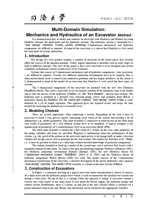
┊┊┊┊┊┊┊┊┊┊┊┊┊装┊┊┊┊┊订┊┊┊┊┊线┊┊┊┊┊┊┊┊┊┊┊┊┊Multi-Domain Simulation:Mechanics and Hydraulics of an Excavator Abstract It is demonstrated how to model and simulate an excavator with Modelica and Dymola by using Modelica libraries for multi-body and for hydraulic systems. The hydraulic system is controlled by a “load sensing” controller. Usually, models containing3-dimensional mechanical and hydraulic components are difficult to simulate. At hand of the excavator it is shown that Modelica is well suited for such kinds of system simulations.1. IntroductionThe design of a new product requires a number of decisions in the initial phase that severely affect the success of the finished machine. Today, digital simulation is therefore used in early stages to look at different concepts. The view of this paper is that a new excavator is to be designed and several candidates of hydraulic control systems have to be evaluated.Systems that consist of 3-dimensional mechanical and of hydraulic components – like excavators – are difficult to simulate. Usually, two different simulation environments have to be coupled. This is often inconvenient, leads to unnecessary numerical problems and has fragile interfaces. In this article it is demonstrated at hand of the model of an excavator that Modelica is well suited for these types of systems.The 3-dimensional components of the excavator are modeled with the new, free Modelica MultiBody library. This allows especially to use an analytic solution of the kinematic loop at the bucket and to take the masses of the hydraulic cylinders, i.e., the “force elements”, directly into account. The hydraulic part is modeled in a detailed way, utilizing pump, valves and cylinders from HyLib, a hydraulics library for Modelica. For the control part a generic “load sensing” control system is used, modeled by a set of simple equations. This approach gives the required results and keeps the time needed for analyzing the problem on a reasonable level.2. Modeling ChoicesThere are several approaches when simulating a system. Depending on the task it may be necessary to build a very precise model, containing every detail of the system and needing a lot of information, e.g., model parameters. This kind of models is expensive to build up but on the other hand very useful if parameters of a well defined system have to be modified. A typical example is the optimization of parameters of a counterbalance valve in an excavator (Kraft 1996).The other kind of model is needed for a first study of a system. In this case some properties of the pump, cylinders and loads are specified. Required is information about the performance of that system, e.g., the speed of the pistons or the necessary input power at the pump shaft, to make a decision whether this design can be used in principle for the task at hand. This model has therefore to be “cheap”, i.e., it must be possible to build it in a short time without detailed knowledge of particular components.The authors intended to build up a model of the second type, run it and have first results with a minimum amount of time spent. To achieve this goal the modeling language Modelica (Modelica 2002), the Modelica simulation environment Dymola (Dymola 2003), the new Modelica library for 3-dimensional mechanical systems “MultiBody”(Otter et al. 2003) and the Modelica library of hydraulic components HyLib (Beater 2000) was used. The model consists of the 3-dimensional mechanical construction of the excavator, a detailed description of the power hydraulics and a generic “load sensing” controller. This model will be available as a demo in the next version of HyLib.3. Construction of ExcavatorsIn Figure 1 a schematic drawing of a typical excavator under consideration is shown. It consists of a chain track and the hydraulic propel drive which is used to manoeuvre the machine but usually not during a work cycle. On top of that is a carriage where the operator is sitting. It can rotate around a vertical axis with respect to the chain track. It also holds the Diesel engine, the hydraulic pumps and control system. Furthermore, there is a boom, an arm and at the end a bucket which is attached via a planar kinematic loop to the arm. Boom, arm and bucket can be rotated by the appropriate cylinders.┊┊┊┊┊┊┊┊┊┊┊┊┊装┊┊┊┊┊订┊┊┊┊┊线┊┊┊┊┊┊┊┊┊┊┊┊┊Figure 2 shows that the required pressures in the cylinders depend on the position. For the “stretched” situation the pressure in the boom cylinder is 60 % higher than in the retracted position. Not only the position but also the movements have to be taken into account. Figure 3 shows a situation where the arm hangs down. If the carriage does not rotate there is a pulling force required in the cylinder. When rotating –excavators can typically rotate with up to 12 revolutions per minute –the force in the arm cylinder changes its sign and now a pushing force is needed. This change is very significant because now the “active” chamber of the cylinder switches and that must be taken into account by the control system. Both figures demonstrate that a simulation model must take into account the couplings between the four degrees of freedom this excavator has. A simpler model that uses a constant load for each cylinder and the swivel drive leads to erroneous results4. Load Sensing SystemExcavators have typically one Diesel engine, two hydraulic motors and three cylinders. There exist different hydraulic circuits to provide the consumers with the required hydraulic energy. A typical design is a Load Sensing circuit that is energy efficient and user friendly. The idea is to have a flow rate control system for the pump such that it delivers exactly the needed flow rate. As a sensor the pressure drop across an orifice is used. The reference value is the resistance of the orifice. A schematic drawing is shown in figure 4, a good introduction to that topic is given in (anon. 1992).The pump control valve maintains a pressure at the pump port that is typically 15 bar higher than the pressure in the LS line (= Load Sensing line). If the directional valve is closed the pump has therefore a stand-by pressure of 15 bar. If it is open the pump delivers a flow rate that leads to a pressure drop of 15 bar across that directional valve. Note: The directional valve is not used to throttle the pump flow but as a flow meter (pressure drop that is fed back) and as a reference (resistance). The circuit is energy efficient because the pump delivers only the needed flow rate, the throttling losses are small compared to other circuits.If more than one cylinder is used the circuit becomes more complicated, see figure 5. E.g. if the boom requires a pressure of 100 bar and the bucket a pressure of 300 bar the pump pressure must be above 300 bar which would cause an unwanted movement of the boom cylinder. Therefore compensators are used that throttle the oil flow and thus achieve a pressure drop of 15 bar across the particular directional valve. These compensators can be installed upstream or downstream of the directional valves. An additional valve reduces the nominal pressure differential if the maximum pump flow rate or the maximum pressure is reached (see e.g. Nikolaus 1994).5. Model of Mechanical PartIn Figure 6, a Modelica schematic of the mechanical part is shown. The chain track is not modeled, i.e., it is assumed that the chain track does not move. Components “rev1”, ..., “rev4” are the 4 revolute joints to move the parts relative to each other. The icons with the long black line are “virtual”rods that are used to mark specific points on a part, especially the mounting points of the hydraulic cylinders. The light blue spheres (b2, b3, b4, b5) are bodies that have mass and an inertia tensor and are used to model the corresponding properties of the excavator parts.The three components “cyl1f”, “cyl2f”,and “cyl3f” are line force components that describe a force interaction along a line between two attachment points. The small green squares at these components represent 1-dimensional translational connectors from theModelica.Mechanics. Translational library. They are used to define the 1- dimensional force law acting between the two attachment points. Here, the hydraulic cylinders described in the next section are directly attached. The small two spheres in the icons of the “cyl1f,cyl2f, cyl3f” components indicate that optionally two point masses are taken into account that are attached at defined distances from the attachment points along the connecting line. This allows to easily model the essential mass properties (mass and center of mass) of the hydraulic cylinders with only a very small computational overhead.The jointRRR component (see right part of Figure 6) is an assembly element consisting of 3 revolute joints that form together a planar loop when connected to the arm. A picture of this part of an excavator, a zoom in the corresponding Modelica schematic and the animation view is shown in Figure 7. When moving revolute joint “rev4” (= the large red cylinder in the lower part of Figure 7; the small┊┊┊┊┊┊┊┊┊┊┊┊┊装┊┊┊┊┊订┊┊┊┊┊线┊┊┊┊┊┊┊┊┊┊┊┊┊red cylinders characterize the 3 revolute joints of the jointRRR assembly component) the position and orientation of the attachment points of the “left”and “right” revolute joints of the jointRRR component are known. There is a non-linear algebraic loop in the jointRRR component to compute the angles of its three revolute joints given the movement of these attachment points. This non-linear system of equations is solved analytically in the jointRRR object, i.e., in a robust and efficient way. For details see In a first step, the mechanical part of the excavator is simulated without the hydraulic system to test this part separatly. This is performed by attaching translational springs with appropriate spring constants instead of the hydraulic cylinders. After the animation looks fine and the forces and torques in the joints have the expected size, the springs are replaced by the hydraulic system described in the next sections.All components of the new MultiBody library have “built-in” animation definitions, i.e., animation properties are mostly deduced by default from the given definition of the multi-body system. For example, a rod connecting two revolute joints is by default visualized as cylinder where the diameter d is a fraction of the cylinder length L (d = L/40) which is in turn given by the distance of the two revolute joints. A revolute joint is by default visualized by a red cylinder directed along the axis of rotation of the joint. The default animation (with only a few minor adaptations) of the excavator is shown if Figure 8. The light blue spheres characterize the center of mass of bodies. The line force elements that visualize the hydraulic cylinders are defined by two cylinders (yellow and grey color) that are moving in each other. As can be seen, the default animation is useful to get, without extra work from the user side, a rough picture of the model that allows to check the most important properties visually, e.g., whether the center of masses or attachment points are at the expected places.For every component the default animation can be switched off via a Boolean flag. Removing appropriate default animations, such as the “centerof- mass s pheres”, and adding some components that have pure visual information (all visXXX components in the schematic of Figure 6) gives quickly a nicer animation, as is demonstrated in Figure 9. Also CAD data could be utilized for the animation, but this was not available for the examination of this excavator.6. The Hydraulics Library HyLibThe (commercial) Modelica library HyLib (Beater 2000, HyLib 2003) is used to model the pump, metering orifice, load compensator and cylinder of the hydraulic circuit. All these components are standard components for hydraulic circuits and can be obtained from many manufacturers. Models of all of them are contained in HyLib. These mathematical models include both standard textbook models (e. g. Dransfield 1981, Merrit 1967, Viersma 1980) and the most advanced published models that take the behavior of real components into account (Schulz 1979, Will 1968). An example is the general pump model where the output flow is reduced if pressure at the inlet port falls below atmospheric pressure. Numerical properties were also considered when selecting a model (Beater 1999). One point worth mentioning is the fact that all models can be viewed at source code level and are documented by approx. 100 references from easily available literature.After opening the library, the main window is displayed (Figure 10). A double click on the “pumps” icon opens the selection for all components that are needed to originate or end an oil flow (Figure 11). For the problem at hand, a hydraulic flow source with internal leakage and externally commanded flow rate is used. Similarly the needed models for the valves, cylinders and other components are chosen.All components are modeled hierarchically. Starting with a definition of a connector –a port were the oil enters or leaves the component – a template for components with two ports is written. This can be inherited for ideal models, e.g., a laminar resistance or a pressure relief valve. While it usually makes sense to use textual input for these basic models most of the main library models were programmed graphically, i.e., composed from basic library models using the graphical user interface. Figure12 gives an example of graphical programming. All mentioned components were chosen from the library and then graphically connected.7. Library Components in Hydraulics CircuitThe composition diagram in Figure 12 shows the graphically composed hydraulics part of the excavator model. The sub models are chosen from the appropriate libraries, connected and the┊┊┊┊┊┊┊┊┊┊┊┊┊装┊┊┊┊┊订┊┊┊┊┊线┊┊┊┊┊┊┊┊┊┊┊┊┊parameters input. Note that the cylinders and the motor from HyLib can be simply connected to the also shown components of the MultiBody library. The input signals, i.e., the reference signals of the driver of the excavator, are given by tables, specifying the diameter of the metering orifice, i.e. the reference value for the flow rate. From the mechanical part of the excavator only the components are shown in Figure 12 that are directly coupled with hydraulic elements, such as line force elements to which the hydraulic cylinders are attached.8. Model of LS ControlFor this study the following approach is chosen: Model the mechanics of the excavator, the cylinders and to a certain extent the pump and metering valves in detail because only the parameters of the components will be changed, the general structure is fixed. This means that the diameter of the bucket cylinder may be changed but there will be exactly one cylinder working as shown in Figure 1. That is different for the rest of the hydraulic system. In this paper a Load Sensing system, or LS system for short, using one pump is shown but there are other concepts that have to be evaluated during an initial design phase. For instance the use of two pumps, or a separate pump for the swing.The hydraulic control system can be set up using meshed control loops. As there is (almost) no way to implement phase shifting behavior in purely hydraulic control systems the following generic LS system uses only proportional controllers.A detailed model based on actual components would be much bigger and is usually not available at the begin of an initial design phase. It could be built with the components from the hydraulics library but would require a considerable amount of time that is usually not available at the beginning of a project.In Tables 1 and 2, the implementation of the LS control in form of equations is shown. Usually, it is recommended for Modelica models to either use graphical model decomposition or to define the model by equations, but not to mix both descrip- tion forms on the same model level.For the LS system this is different because it has 17 input signals and 5 output signals. One might built one block with 17 inputs and 5 outputs and connect them to the hydraulic circuit. However, in this case it seems more understandable to provide the equations directly on the same level as the hydraulic circuit above and access the input and output signals directly. For example, ”metOri1.port_A.p” used in table 2 is the measured pressure at port_A of the metering orifice metOri1. The calculated values of the LS controller, e.g., the pump flow rate “pump.inPort.signal[1] = ...” is the signal at the filled blue rectangle of the “pump” component, see Figure 12).The strong point of Modelica is that a seamless integration of the 3-dimensional mechanical library, the hydraulics library and the non standard, and therefore in no library available, model of the control system is easily done. The library components can be graphically connected in the object diagram and the text based model can access all needed variables.9. Some Simulation ResultsThe complete model was built using the Modelica modeling and simulation environment Dymola (Dymola 2003), translated, compiled and simulated for 5 s. The simulation time was 17 s using the DASSL integrator with a relative tolerance of 10-6 on a 1.8 GHz notebook, i.e., about 3.4 times slower as real-time. The animation feature in Dymola makes it possible to view the movements in an almost realistic way which helps to explain the results also to non-experts, see Figure 9.Figure 13 gives the reference signals for the three cylinders and the swing, the pump flow rate and pressure. From t = 1.1 s until 1.7 s and from t = 3.6 s until 4.0 s the pump delivers the maximum flow rate. From t = 3.1 s until 3.6 s the maximum allowed pressure is reached. Figure 14 gives the position of the boom and the bucket cylinders and the swing angle. It can be seen that there is no significant change in the piston movement if another movement starts or ends. The control system reduces the couplings between the consumers which are very severe for simple throttling control.Figure 15 shows the operation of the bucket cylinder. The top figure shows the reference trajectory, i. e. the opening of the directional valve. The middle figure shows the conductance of the compensators. With the exception of two spikes it is open from t = 0 s until t = 1 s. This means that in┊┊┊┊┊┊┊┊┊┊┊┊┊装┊┊┊┊┊订┊┊┊┊┊线┊┊┊┊┊┊┊┊┊┊┊┊┊that interval the pump pressure is commanded by that bucket cylinder. After t = 1 s the boom cylinder requires a considerably higher pressure and the bucket compensator therefore increases the resistance (smaller conductance). The bottom figure shows that the flow rate control works fine. Even though there is a severe disturbance (high pump pressure after t = 1 s due to the boom) the commanded flow rate is fed with a small error to the bucket cylinder.10. ConclusionFor the evaluation of different hydraulic circuits a dynamic model of an excavator was built. It consists of a detailed model of the 3 dimensional mechanics of the carriage, including boom, arm and bucket and the standard hydraulic components like pump or cylinder. The control system was not modeled on a component basis but the system was described by a set of nonlinear equations.The system was modeled using the Modelica MultiBody library, the hydraulics library Hylib and a set of application specific equations. With the tool Dymola the system could be build and tested in a short time and it was possible to calculate the required trajectories for evaluation of the control system.The animation feature in Dymola makes it possible to view the movements in an almost realistic way which helps to explain the results also to多畴模拟:挖掘机的机械学和液压学概要:通过使用用于多体和液压系统的Modelica程序库,示范通过Modelica和Dymola如何模拟和仿真挖掘机。
机械英文外文翻译一种新的电动葫芦驱动起重机
A new electric hoist drive for CranesA new system of electric hoist drive has been developed ,and its success has been demonstrated in practical use. For the types of hoist for which it is particularly intended this system provides a closer approach to the ideal characteristics than has previously been available. Although the system is not intended for use in all of the important types of hoist, it is expected that further experience and additional study of details and refinements will broaden its field of application beyond that which has, to date, been established in practice.The Ideal CharacteristicsAmong the several hoisting applications for which the new system is believed to be suitable, the high-grade heavy-duty indoor cranes in steel mills and heavy machine shops may be considered typical. A study of the requirements indicates that the ideal characteristics for a crane of this type and of certain other types are principally as follows:1.The same manipulation of the controller to any position in thelowering direction should cause the motor either to deliver power for lowering an empty hook or to absorb power for the proper lowering ofa load, whichever is required by the conditions at that moment.2.Maximum hoisting speed at empty hook should be a definite value,approximately twice the speed at rated load.3.At the full-speed hoisting position of the controller the stalled torqueshould be limited to a reasonable overload value.4.At the first-speed hoisting position the speed-torque curve should berelatively flat, having a very low speed at empty hook but a substantial stalled torque.5.The maximum lowering speed at empty hook should be a definiteselected value, between 160 per cent and twice rated hoisting speeds 6.Maximum speed of lowering rated load should be substantially lessthan at empty hook, and maximum speed of lowering maximum load should be less than that of lowering rated load,7. The minimum lowering speeds, that is, the speeds at the firstlowering-speed position of the controller should be nearlyalike .irrespective of load. If readily attainable, it is preferable thatthis lowering speed be less at heavy loads than at partial loads orempty hook.8. The electric equipment must have in the lowering direction asubstantial margin, so that, when the maximum load which can belift is handled, the torque capacity available in lowering direction is ample to maintain dependable control of the load under the mostadverse conditions9. A safe and reasonably smooth retardation and stop must occur automatically in the event of failure of incoming power and other emergencies.10. The regulating means by which the sixth, and seventh requirements are met must not be capable of stalling a load which is being lowered, however great that load may be, at any lowering position of the controller.11. The electric equipment should be self-protective against abase, either of itself or of the mechanical equipment, under the condition of rapid and unrestrained movement of the controller handle.12. It is usually important that the holding brake be so controlled automatically that in regular service it is not required to supply any large part of the retardation effort.The New SystemThe ideal characteristics for the applications under approximated closely by the development of a radical improvement of the Ward-Leonard system, the principal feature of which is the addition of an exciter of unusual design embodying a cross-flux principle. By this means, a characteristic is obtained in which the voltage of this cross-flux exciter is responsive in a unique manner to the variations of magnitude and polarityof the current in the "loop" circuit, that is, the local circuit comprised by the armatures of the generator and hoist motor. At zero "loop" current the voltage of this exciter is at its maximum. At substantial increases of "loop" current, irrespective of polarity, the voltage of this exciter decreases, and at the maximum overload values of the "loop" current the voltage closely approaches zero. The voltage generated by this exciter provides the excitation of the generator field and modifies the excitation of the motor field. By means of the generator and motor- excitation characteristics thus provided, characteristics of speed versus load are obtained of the kind illustrated later in the paper.The 9th and 12th requirements listed in the foregoing for the ideal crane hoist are met respectively by a simplified arrangement of an emergency dynamic-braking resistor in the hoist-motor armature circuit and by an improvement in the control details of the magnet brake. These two features are not dependent upon the cross-flux-exciter principle .they were, however , developed as contributions to the same project , namely, the attempt to achieve the al-most perfect crane-hoist drive. Because of lack of space, these features are not described.Construction of the ExciterFigure 3 illustrates diagrammatically the principles of construction of thecross-flux exciter in its basic form. Although multipolar machines are possible,the exciters built to date are bipolar, by which is meant that the armature-winding and commutator connections are those of a normal bipolar machine. Four pole pieces are provided. In Figure 3 the two upper pole pieces constitute one“pole” insofar as relates to the generation of the output voltage. The two lower pole pieces constitute the other “pole ”.For reasons which will appear, a degree of artificial saturation is introduced in the pole pieces, for example, by notches the sides of the pole pieces as indicated in Figure 3.In one design which has been used, the diametrically opposite pole pieces p1 are duplicates ,each having a high degree of artificial saturation; the diametrically opposite pole pieces P2 are duplicates but have a much less degree of artificial saturation. For the general explanation let all pole pieces and their respective air gaps be considered duplicate.To avoid a possible misunderstanding it should be noted that in Figure 3 the positions of the brushes as shown are diagrammatic only and represent the positions of the armature slot conductors at which theyundergo commutation.Characteristics of the ExciterIn the circuit arrangement in which this exciter is used in the system, armature reaction and armature IR drop exciter tend, if not offset, to be of more than negligible effect, but they can be compensated sufficiently to make them almost negligible; consequently the explanation of the operation of the cross-flux exciter can be based upon a study of theno-load saturation curves of the respective flux paths. The upper lower part of Figure 4. If compensation usually important to offset or minimize part of Figure 4 represents the no-load saturation curve, not of the entire machine but of each of the two duplicate and practically independent flux paths, P1 and P2, respectively.H1 represents the selected field strength of the separately excitedmain-field winding which remains substantially constant throughout. When the current in the cross field is zero, each flux path of the exciter causes the generation of a voltage E0, and the total voltage generated is 2Eo plotted in the lower part of Figure 4 at zero cross-field ampere turns. Now assume a cross-field strength of H2. In flux path P1 the value of H2 is additive to H1, hence the voltage generated in this flux path is now Ea. In flux path P2 the value of H2 is subtractive from H1; hence the voltage generated in this flux path is now Eb. The total voltage generated isEa+Eb, as plotted in the lower part of Figure 4. Since saturation increasesbeyond point E0 and decreases below E0, voltage Ea+Eb is substantially less than 2Eo. At a cross-field strength of 2H2 the further increment of voltage generated in path P1 is very small, but the decrement of voltage generated in path P2 is large-in fact the voltage of path P2 reverses. The corresponding total voltage EC+Ed accordingly is much reduced. When the two magnetic circuits are duplicate, and when the numbers of turns of the respective windings are equal upon all pole pieces, the negative voltage generated by path P2 cannot become quite so great as the voltage generated by path P1; hence the o total voltage of the exciter never reaches zero. When the polarity of the cross-filed current is opposite to the foregoing, path P2 behaves as did path P1 in the foregoing and conversely. Hence the characteristic of voltage generated versuscross-field (that is "loop" circuit) current tends to repeat symmetrically about the left-hand side of the vertical axis in the lower part of Figure 4. If compensation for armature reaction is not provided, this characteristic shows a departure from symmetry about the two sides of the vertical axis. The dissymmetry caused by armature reaction may or may not be practically disadvantageous, according to the specific design and application. To date, a design of exciter having closely symmetrical characteristics about the vertical axis has not been built. In the first design the armature reaction was not compensated. In a later design of a larger exciter the armature reaction was compensated, but a dissymmetry ofcharacteristics was purposely introduced by means of unlike proportions of the respective flux paths.If a moderately greater value of separately excited field is held, represented by a higher value of H1 in Figure 4, a voltage characteristic is obtained of similar shape having higher voltages throughout, and conversely for a moderately smaller of separately excited field.Design and Arrangement of SystemThe generator is of normal design. Its main field is wound with the maximum practicable cross section of copper in order to provide the desired high no-load voltage with the least oversize of generator. Such a field winding provides a generator time constant which, in combination with the circuit arrangement and cross-flux- exciter-characteristics, limits the peak currents to values which are suitable for the electric equipment and the hoist system.The hoist motor has a nonstandard main-field winding for a variable separate excitation but in other respects is of the type which is standard for high-class crane-hoist installations.In order to provide the desired variation of the hoist-motor field, the cross-flux exciter is designed for a maximum voltage substantially less than that of the constant-voltage main-excitation bus. One terminal of the cross-flux exciter, negative as shown in Figure 5, is connected permanently to the main-excitation bus terminal of like (that is negative) polarity , Thus between the positive terminals of these two sources of excitation a variable voltage is available which is the difference of the two voltages.Because the cross-flux exciter is used for two purposes, its armature current is the difference of the generator-field and motor-field currents. Thus at zero "loop" current the exciter armature current is at its maximum value as output. At rated "loop" current the generator-field current and motor-field current are nearly equal; hence the exciter armature current is not far from zero. At maximum "loop" current, when the exciter voltage is low accordingly, most of the hoist-motor field current becomes input into the exciter which accordingly acts regeneratively. The uncorrected effect of armature IR drop would be to decrease the maximum effective voltage of the exciter by a more than negligible percentage, but also to increase the minimum voltage of the exciter by a large percentage over the desired low value. It is principally for these reasons that the exciter is compounded as has been mentioned.Speed-Torque CharacteristicsThe characteristics of the system are determined principally by the manner in which the generator voltage varies, subject, however, to the modifying effect of the IR drop of the "loop" circuit and the additional modifying effect of the motor-field variation .when the generator field is excited and controlled as described, the characteristics of generator voltage and of motor counter electromotive motive force with respect to "loop" current will resemble those of Figure 6, in which the curves of generator voltage represent not terminal voltage but voltage generated within the generator.The characteristics shown in Figure 7 and figure 8 are considered to be particularly suitable for cranes in steel plants and heavy machine shops, subject to the possible exception that the highest-speed lowering characteristics there shown may be faster than considered desirable.it is a simple matter to real just so as to reduce the speeds of the fastest lowering characteristic and to redistribute the intermediate characteristics accordingly.With the possible exception of an extraordinary combination ofconditions a crane is never called upon to lower a hook load greater than that which it is capable of picking up and hoisting. However, in the factory tests of the develop mental sample electric "live" loads were applied equivalent to hook loads substantially greater than any which could be lifted, as shown in Figure 8. At such excessive loads curves 1L show increases in speed. These, however, do not involve any tendency toward instability but are merely the result of increased IR drop of the "loop" circuit throughout the excessive overloads at which the generator voltage is at a nearly constant minimum. Throughout the entire over load range the hoist-motor excitation increases until at maximum overloads including those which are impossible in practice the motor is highly saturated, and hence in a very stable condition.ConclusionThe hoisting-machinery art includes many different application. Some of these types of hoist have relatively unexacting requirement which are met acceptably by various simple systems of electric drive. several systems of electric-hoist drive have been developed , each of which has certain specialized modifications which are particularly advantageous .for certain exacting applications but which are irrelevant or disadvantageous for certain other hoisting applications whose requirements are equally exacting. but different. The electric system described in this paper is not to be considered as preferable or even applicable for every important typeof hoist, but it is intended for use in several types of hoist in which, notwithstanding certain substantial differences of design and use, the speed-torque requirements are similar.No installations have yet been made in large heavy-duty indoor cranes such as are typical of steel plants and heavy machine shops. However, the results first demonstrated by the developmental sample and confirmed in practice by the Fontana Dam installation indicate the suitability and advantages of the system for heavy-duty indoor cranes. It seems reasonable to expect that with further experience and additional study of details and refinements the field of application will be broadened further.一种新的电动葫芦驱动起重机一个新的电动葫芦驱动器的系统已经研制成功,已经在实际使用中证明了它的成功。
数控车床主轴部件机械外文文献翻译、中英文翻译、外文翻译
数控车床主轴部件机械外文文献翻译、中英文翻译、外文翻译数控车床主轴部件车床是一种主要用于加工旋转表面和平整边缘的机床。
根据使用目的、结构、刀具数量和自动化程度的不同,车床可以分为普通车床、万能车床、转塔车床、立式车床、自动车床和特殊车床。
虽然车床种类繁多,但它们在结构和操作原理上具有共同特性。
普通车床是最常用的代表类型,下面将介绍普通车床的主要部分。
车床床身是车床的主骨架,由两个垂直支柱上的水平横梁组成。
为减振,它通常由灰铸铁或球墨铸铁铸造而成。
车床床身上有导轨,可以让大拖板轻松纵向滑动。
车床床身的高度应适当以方便技师工作。
主轴箱固定在车床床身的左侧,包括轴线平行于导轨的主轴。
主轴通过齿轮箱驱动,齿轮箱可以提供多种不同的速度(通常是6到18速)。
现代车床有些采用无级调速主轴箱,采用摩擦、电力或液压驱动。
主轴往往是中空的,纵向有一通孔,可以通过此孔进给棒料。
同时,此孔为锥形表面,可以安装普通车床顶尖。
主轴外表面是螺纹,可以安装卡盘、花盘或类似的装置。
尾架总成包括底座、尾架体和套筒轴。
底座是能在车床床身上沿导轨滑动的铸件,有定位装置,可以让整个尾架根据工件长度锁定在任何需要位置。
使用手轮和螺杆,与螺杆啮合的是一固接在套筒轴上的螺母。
套筒轴开口端的孔是锥形的,能安装车床顶尖或诸如麻花钻和镗杆之类的工具。
套筒轴通过定位装置能沿着它的移动路径被锁定在任何点。
大拖板的主要功能是安装刀具和产生纵向和/或横向进给。
它实际上是一由车床床身V形导轨引导的、能在车床床身主轴箱和尾架之间滑动的H形滑块。
大拖板可以手动或通过溜板箱和光杆(进给杆)或丝杆(引导螺杆)机动。
本文介绍了在传统普通车床上进行的各种机加工作业。
但是,需要注意的是现代计算机数控车床具有更多的功能,并且可以进行其他操作,例如仿型。
圆柱面车削是所有车床操作中最简单也是最常见的。
工件旋转一整圈产生一个圆心落在车床主轴上的圆;由于刀具的轴向进给运动,这种动作重复许多次。
机械制造专业外文翻译--锻造
英文原文:A.1 FORGINGBulk defirnnation of metals refers to various processes, such as forging, rolling, or extruding, where there is a controlled plastic flow or working of metals into useful shapes. The most well known of these processes is forging where deformation is accomplished by means of pressure, impact blows, or a combination of both.Hammer ForgingHanuner forging consists of striking the hot metal with a large semiautomatic hammer. If no dies are involved, the forging will be dependent mainly on the skill of the operator. If closed or impression dies are used, one blow is struck for each of several (lie cavities. A- gain, productivity and quality depend to a large degree on the skill of the hanimer operator and the tooling.Press ForgingPress forging is characterized by a slow squeezing action. Again, open or closed dies may be used. The open dies are used chiefly for large, simple-geometry parts that are later machined to shape. Closed-die forging relies less on operator skill awl more on the design of the preform and forging dies.2 As an example of the versatility of the process, newer developments have made it possible to produce bevel gears with straight or helical teeth. Rotation of the die (luring penetration will press bevel gears with spiral teeth.Open-die ForgingOpen-die forging is distinguished by the fact that the metal is never completely confined as it is shaped by various dies. Most open-die forgings are produced on flat, V, or swaging dies. Round swaging (lies and V dies are used in pairs or with a flat die. The top (lie is attached to the ram of the press, and the bottom die is attached to the hammer anvil or, in the case of press open-die forging, to the press bed.As the workpiece is hammered or pressed, it is repeatedly manipulated between the dies until hot working forces the metal to the final dimensions, as-shown in Fig. 1. After forging, the part is rough- and finished-machined. As an example of the amount of material allowed for machining, a 6.5 in. diameter shaft would have to be forged to 7.4 in. dianieter.In open-die forging of steel, a rule of thumb says that 50 lb of falling weight is required for each square inch of cross section.Impression-die ForgingIn the simplest example of impression-die forging, two dies are brought together, and the workpiece undergoes plastic deformation until its enlarged sides touch the side walls of the die (Fig. 2). A small amount of material is forced outside the die impression, forming flash that is gradually thinned. The flash cools rapidly and presents increased resistance to deformation, effectively becoming a part of the tool, and helps build up l)ressUre inside the bulk of the work- piece that aids material flow into unfilled impressions.Closed-die forgings, a special form of impression-die forging, does not depend on theformation of flash to achieve complete filling of the (lie. Thus closed-die forging is considerably more demanding on die design. Since pressing is often completed in one stroke, careful control of the workpieee volume is necessaiy to achieve complete filling without generating extreme pressures in the dies from overfilling.Extrusion ForgingAs with upsetting, extrusion forging is often accomplished by cold working. Three principal types of metal displacement by plastic flow are involved. Backward and forward, tube, and impact extrusion are shown in Fig. 3. The metal is placed in a container and corn- pressed by a ram movement until pressure inside the metal reaches flow-stress levels. The workpiece completely fills the container, and additional pressure causes it to leave through an orifice and form the extruded product.Extruded products may be either solid or hollow shapes. Tube extrusion is used to produce hollow shapes such as containers and pipes. Reverse-impact extrusion is used for mass production of aluminum cans. The ram hits a slug of metal in the die at high impact, usually 15 times the yield strength of the metal, which causes it to flow instantaneously up the walls of the die. Other common hollow extrusion products are aerosol cans, lipstick cases, flashlight cases, and vacuum bottles. Secondary operations, such as heading, thread rolling, dimpling, and machining, are often needed to complete the items.Generally steel impacts are limited to 2.5 times the punch diameter. Hydraulic presses areused for loads of over 2000 tons because they have a greater variation in stroke length, speed,and other economic advantages. Tolerances vary with materials arid design, hut productionruns calling for 0.002- to 0.005-in, tolerance are regularly made.Roll ForgingRoll forging in its simplest form consists of a heated billet passing between a pair of rollsthat deform it along its length (Fig. 8-4). Compared to conventional rolling processes, therolls are relatively small in diameter and serve as an arbor into which the forging tools aresecured. The active surface of the tool occupies only a portion (usually half) of the rollcircumference to accommodate the full cross section of the stock.The reduction of the cross section obtainable in one pass is limited by the tendency of thematerial to spread and form an undesirable flash that may be forged into the surface as a90rota- defect in the subsequent operations. The workpiece is int roduced repeatedly withtion between passes.Ring RollingRing rolling offers a homogeneous circumferential grain flow, ease of fabrication andmachining, and versatility of material size . Manu- facture of a rolled ring starts with asheared blank, which is forged to a pancake, punched, and pierced.There is no limit to the size of the rolled rings, ranging from roller-bearing sleeves to Fig.4 Roll forging rings 25 ft in diameter with face heights of 80 in. Various profiles may berolled by suitably shaping the driven, idling rolls.CAD/CAM in ForgingCAD/CAM is being increasingly applied to frging. Using the three-dimensional description of a machined part, which may have been computer designed, it is possible to generate the geometry of the associated forging. Thus the forging sections can be obtained from a common (laiR base. Using well-known techniques, forging loads and stresses can be obtained and flash dimensions can be selected for each section where metal flow is approximated as ro dimensional (plane strain or axisymmetric ). In some relatively simple section geomethes, computer simulation can be conducted to evaluate initial guesses on preform sections. Once the preform geometry has been developed to the designer¡¯s satisfaction, this geometric data base can utilized to write NC part programs to obtain the NC tapes or disks for machining.A.2 HEAT TREATMENT OF METALAnnealingThe word anneal has been used before to describe heat-treating processes for softening and regaining ductility in connection with cold working of material. It has a similar meaning when used in connection with the heat treating of allotropic materials. The purpose of full annealing is to decrease hardness, increase ductility, and sometimes improve machinability of high carbon steels that might otherwise be difflcult to cut. The treatment is also used to relieve stresses, refine grain size, and promote uniformity of structure throughout the material.Machinability is not always improved by annealing. The word machinability is used to describe several interrelated factors, including the ability of a material to be cut with a good surface finish. Plain low carbon steels, when fully annealed, are soft and relatively weak, offering little resistance to cutting, but usually having sufficient ductility and toughness that a cut chip tends to puli and tear the surface from which it is removed, leaving a comparatively poor quality surface, which results in a poor machinability rating. For such steels annealing may not be the most suitable treatment. The machinability of many of the higher plain carbon and most of the alloy steels can usually be greatly improved by annealing, as they are often too hard and strong to be easily cut at any but their softest condition .The procedure for annealing hypoeutectoid steel is to heat slowly to approximately 60C︒above the Ac3 line, to soak for a long enough period that the temperature equalizes throughout the material and homogeneous austenite is formed, and then to allow the steel to cool very slowly by cooling it in the furnace or burying it in lime or some other insulating material. The slow cooling is essential to the precipitation of the maximum ferrite and the coarsest pearlite to place the steel in its softest, most ductile, and least strained condition. NormalizingThe purpose of normalizing is somewhat similar to that of annealing with the exceptions that the steel is not reduced to its softest condition and the pearlite is left rather fine instead of coarse. Refinement of grain size, relief of internal stresses, and improvement of structural uniformity together with recovery of some ductility provide high toughness qualities in normalized steel. The process is frequently used for improvement of machinability and for stress nlief to reduce distortion that might occur with partial machining or aging.The procedure for normalizing is to austenitize by slowly heating to approximately80above the Ac3 or Accm3 temperature for hypoeutectoid or hypereuteetoid steels, C︒respectively; providing soaking time for the formation of austenite; and cooling slowly in still air. Note that the steels with more carbon than the eutectoid composition are heated above the Aom instead of the Ac used for annealing. The purpose of normalizing is to attempt to dissolve all the cementite during austenitization to eliminate, as far as possible, the settling of hani, brittle iron carbide in the grain boundaries. The desired decomposition products are smallgrained, fine pearlite with a minimum of free ferrite and free cementite. SpheroidizingMinimum hardness and maximum ductility of steel can he produced by a process called spheroidizing, which causes the iron carbide to form in small spheres or nodules in a ferrite matrix, in order to start with small grains that spheroid ize more readily, the process is usually performed on normalized steel. Several variations of processing am used, but all reqllin the holding of the steel near the A1 temperature (usually slightly below) for a number of hours to allow the iron carbide to form on its more stable and lower energy state of small, rounded glohules.The main need for the process is to improve the machinability quality of high carbonsteel and to pretreat hardened steel to help produce greater structural uniformity after quenching. Because of the lengthy treatment time and therefore rather high cost, spheroidizing is not performed nearly as much as annealing or normalizing.Hardening of SteelMost of the heat treatment hardening processes for steel are basel on the production of high pereentages of martensite. The first step. therefore, is that used for most of the other heat-treating processes-treatment to produce austenite. Hypoeutectoid steels are heated to approximately 60CC above the Ac3 temperature and allowed to soak to obtain temperature unifonnity and austenite homogeneity. Hypereutectoid steels are soaked at about 60CC above the A1 temperature, which leaves some iron carbide present in the material.The second step involves cooling rapidly in an attempt to avoid pearlite transformation by missing the nose of the i-T curve. The cooling rate is determined by the temperature and the ability of the quenching media to carry heat away from the surface of the material being quenched and by the conduction of heat through the material itself. Table1 shows some of the commonly used media and the method of application to remove heat, arranged in order of decreasing cooling ability.High temperature gradients contribute to high stresses that cause distortion and cracklug, so the quench should only as extreme as is necessary to produce the desired structure. Care must be exercised in quenching that heat is removed uniformly to minimize thermal stresses.For example, a long slender bar should be end-quenched, that is, inserted into the quenching medium vertically so that the entire section is subjected to temperature change at one time. if a shape of this kind were to be quenched in a way that caused one side to drop in temperature before the other, change of dimensions would likely cause high stresses producing plastic flow and permanent distortion.Several special types of quench are conducted to minimize quenching stresses and decrease the tendency for distortion and cracking. One of these is called martempering and consists of quenching an austenitized steel in a salt at a temperature above that needed for the start of martensite formation (Ms). The steel being quenched is held in this bath until it is of uniform temperature but is removed before there is time for fonnation of bainite to start. Completion of the cooling in air then causes the same hard martensite that would have formed with quenching from the high temperature, but the high thermal or ¡°quench¡± stresses that are the primary source of cracks and warping will have been eliminated.A similar process performed at a slightly higher temperature is called austempering. In this case the steel is held at the bath temperarnre for a longer period, and the result of the isothermal treatment is the formation of bainite. The bainite structure is not as hard as the martensite that could be formed from the same composition, but in addition to reducing the thermal shock to which the steel would be subjected under normal hardening procedures, ii is unnecessary to perform any further treatment to develop good impact resistance in the high hardness rangeTemperingA third step usually required to condition a hardened steel for service is tempering, or as it is sometimes referred to, drawing. With the exception of austempered steel, which is frequently used in the as-hardened condition, most steels are not serviceable “as quenched”. The drastic cooling to produce martensite causes the steel to be very hard and to contain both macroscopic and microscopic internal stresses with the result that the material has little ductility and extreme brittleness. Reduction of these faults is accomplished by reheating the steel to some point below the A1 (lower transformation) temperature. The stnictural changes caused by tempering of hardened steel are functions of both time and temperature, with temperature being the most important. It should be emphasized that tempering is not ahardening process, but is, instead, the reverse. A tempered steel is one that has been hardened by heat treatment and then stress relieved, softened, and provided with increased ductility by reheating in the tempering or drawing procedure.The magnitude of the structural changes and the change of properties caused by tempering depend upon the temperature to which the steel is reheated. The higher the ternperatun, the greater the effect, so the choice of temperature will generally depend on willingness to sacrifice hardness and strength to gain ductility and toughness. Reheating to below lOOt has little noticeable effect on hardened plain carbon steel. Between lO(YC and 200T, there is evidence of some structural changes. Above 200T marked changes in structure and properties appear. Prolonged heating at just under the A1 temperature will result in a spheroidized structure similar to that produced by the spheroidizing process.In commercial tempering the temperature range of 25O-425 is usually avoided because of an unexplained embrittlement, or loss of ductility, that often occun with steels ternpered in this range. Certain alloy steels also develop a ¡°temper brittleness¡± in the tempera- ture range of 425-600C︒, particularly when cooled slowly from or through this range of temperature. When high temperature tempering is necessary for these steels, they are usually heated to above 600C︒and quenched for rapid cooling. Quenches from this temperature, of course, do not cause hardening because austenitization has not been accomplished.中文译文:B.1 锻造金属变形方法有多种,比如通过锻造、滚压或挤压,使金属的塑性流动或加工受到控制而得到有用的形状。
工程力学外文翻译范文工程力学英文什么说
工程力学外文翻译范文工程力学英文什么说工程力学,英文是:engineering mechanics。
例句:并基于工程力学对充填体强度及其安全性进行了分析研究。
An analysis study was conducted on the strength and safety of the backfill materialbased on the engineering mechanics.详细解释:engineering英[?end???n??r??] 美[?end???n?r??]n. 工程(学),工程师行业; 操纵,管理; 土木工程,工事; 开车技术;[例句]He has not studied mechanics or engineering.他没有学习过力学和工程学。
mechanics 英[m?'k?n?ks] 美[m??k?n?ks]n. 力学; 机械学; 构成法; 技术;[例句]He has not studied mechanics or engineering.他没有学习过力学和工程学。
机械学院工程力学专业的英文是Engineering Mechanics major in Mechanical Engineering。
工程力学专业本专业培养具备力学基础理论知识、计算和试验能力,能在各种工程(如机械、土建、材料、能源、交通、航空、船舶、水利、化工等)中从事与力学有关的科研、技术开发、工程设计和力学教学工作的高级工程科学技术人才。
本专业主要学习力学、数学基本理论和知识,受到必要的工程技能训练,具有应用计算机和现代实验技术手段解决与力学有关的工程问题的基本能力。
《工程力学》是土木工程专业主要的技术基础课,而且也是学生公认的一门比较难学的课程。
该课程不但要求学生能正确理解基本概念,而且要求学生要学会用所学内容求解各种工程和生活中的各种力学问题。
所以该课程要求学生具有较好的高等数学基础。
- 1、下载文档前请自行甄别文档内容的完整性,平台不提供额外的编辑、内容补充、找答案等附加服务。
- 2、"仅部分预览"的文档,不可在线预览部分如存在完整性等问题,可反馈申请退款(可完整预览的文档不适用该条件!)。
- 3、如文档侵犯您的权益,请联系客服反馈,我们会尽快为您处理(人工客服工作时间:9:00-18:30)。
Optimization design of spur gear reducer based on genetic algorithm
Zhang Xiao-qin1 21 College of Mechanical Engineering Yan Shan University 2 College of Mechanical and Electrical Engineering Hebei Normal University of Science & Technology
Qinhuangdao China Hu Zhan-qi College of Mechanical Engineering Yan Shan University Qinhuangdao China
Lun Cui-fen Yu Jing-jing College of Mechanical and Electrical Engineering Hebei Normal University of Science & Technology Qinhuangdao China
Abstract—Gear reducer is one of the most widely used methods in mechanical transmission, optimization of which is of great significance in improving the bearing capacity, prolonging service life and reducing its size and quality. By Visual Basic programming mixed with MATLAB, automatic optimization design for gear reducer is realized in the paper, design efficiency and quality greatly improved. Genetic algorithm and genetic toolbox of MATLAB is used when calculating, with the advantages of simple programming, good reliability and high efficiency.
Keywords-reducer; optimization of design; genetic algrithm; MATLAB
I.INTRODUCTION
Gear reducer is one of the most widely used methods in mechanical transmission, which has many advantages, such as accuracy ratio, high efficiency, stable and accurate. With the rapid development of science and technology it will make continuous progress. So it is of great economic significance to improve the bearing capacity, prolong the service life and decrease its size and quality. Optimized design of gear reducer, choosing the best parameters is a kind of important ways to improve the bearing capacity, reduce weight and cost[1][2][3].
Optimization design of gear reducer includes the continuous variables and discrete variables. The traditional method is to round the optimal design to the adjacent discrete points. Thus, design point might run out of the feasible region, besides traditional optimization method is mostly based on gradient algorithm, which is likely trapped into local minimum search. Many studies indicate that the genetic algorithm has strong ability of general optimization, which is very effective in treating optimization problem containing continuous and discrete variables[4][5].
Based on single spur gear reducer, the paper establishes the mathematical model for optimization design of gear reducer, with the purpose of minimum volume or quality. By using
genetic algorithm and genetic toolbox of MATLAB to get optimum solution quickly and accurately, the efficiency and quality of gear design is greatly improved and the production cycle is shorten.
II.MATHEMATICAL MODEL FOR OPTIMIZATION DESIGN
Optimization design of gear reducer is usually given power P, gear ratio i, input speed n1 and other technical conditions and requirements, to seek a group of design parameters that achieve technical and economic indexes of a reducer optimum.
A single spur gears reducer transmission diagram and gear structure is shown in Fig 1. Assume that the gear ratio is known as i, the input power P(kW), active gear speed n1(r/min), it’s required to figure out various design parameters to make the reducer as light as possible under the condition that the strength and stiffness are guaranteed.
Figure 1. Single spur gear reducer and gear structure Since the size of the gear and axis is to determine the size and quality of reducer assembly, the objective function is the sum of their value, without considering cabinet and bearing volume or quality. According to the fig 1, the sum of the
978-1-4244-7161-4/10/$26.00 ©2010 IEEEvolume of gears and shafts can be approximately expressed as follows:
())1(42.14)(3.04)(421221222222jjjjjnjnjwjwjojldbddbddbddV×+»¼º«¬ª×−+×−+−=¦¦
==π
πππ
Where d01=mz1;d02=mz1i;dw1=mz1-8m;dw2=mz1i-8m;dn1=1.6d1;dn2=1.6d2.
From above equation, it can be seen that if i have been given beforehand, the volume of gear and shaft is determined only by face width b, the number of pinion teeth z1, modulus m, shaft diameter d1 and d2 and distance l between two bearings, i.e. V is the function of these parameters: V=f(b,z1,m,d1,d2,l1,l2).
Take these variables as design variables and expressed as: X=[x1,x2,x3,x4,x5,x6]= [b,z1,m,d1,d2,l] (2) Thus the objective function can be expressed as: f(X)=V=f(x1,x2,x3,x4,x5,x6) (3)The constraint conditions can be given by follows [1][2]: •Avoiding undercut condition z1 should be greater than the smallest number 17, i.e. g1(X)=-x2-17 (4)