机械外文翻译中英文
机械外文翻译中英文

附录附录1英文原文Rolling Contact BearingsThe concern of a machine designer with ball and roller bearings is fivefold as follows:(a) life in relation to load; (b) stiffness,ie.deflections under load; (c) friction; (d) wear; (e) noise. For moderate loads and speeds the correct selection of a standard bearing on the basis of a load rating will become important where loads are high,although this is usually of less magnitude than that of the shafts or other components associated with the bearing. Where speeds are high special cooling arrangements become necessary which may increase fricitional drag. Wear is primarily associated with the introduction of contaminants,and sealing arrangements must be chosen with regard to the hostility of the environment.Because the high quality and low price of ball and roller bearing depends on quantity production,the task of the machine designer becomes one of selection rather than design. Rolling-contact bearings are generally made with steel which is through-hardened to about 900HV,although in many mechanisms special races are not provided and the interacting surfaces are hardened to about 600HV. It is not surprising that,owing to the high stresses involved,a predominant form of failure should be metal fatigue, and a good deal of work is based on accept values of life and it is general practice in bearing industry to define the load capacity of the bearing as that value below which 90 percent of a batch will exceed life of one million revolutions.Notwithstanding the fact that responsibility for basic design of ball and roller bearings rests with the bearing manufacturer, the machine designer must form a correct appreciation of the duty to be performed by the bearing and be concerned not only with bearing selection but with the conditions for correct installation.The fit of the bearing races onto the shaft or onto the housings is of critical importance because of their combined effect on the internal clearance of the bearing as well as preserving the desired degree of interference fit. Inadequate interference can induce serious trouble from fretting corrosion. The inner race is frequently located axially by against a shoulder. A radius at this point is essential for the avoidance of stress concentration and ball races are provided with a radius or chamfer to follow space for this.Where life is not the determining factor in design, it is usual to determine maximum loadingby the amount to which a bearing will deflect under load. Thus the concept of "static load-carrying capacity" is understood to mean the load that can be applied to a bearing, which is either stationary or subject to slight swiveling motions, without impairing its running qualities for subsequent rotational motion. This has been determined by practical experience as the load which when applied to a bearing results in a total deformation of 0.0025mm for a ball 25mm in diameter.The successful functioning of many bearings depends upon providing them with adequate protection against their environment, and in some circumstances the environment must be protected from lubricants or products of deterioration of the bearing design. Moreover, seals which are applied to moving parts for any purpose are of interest to tribologists because they are components of bearing systems and can only be designed satisfactorily on basis of the appropriate bearing theory.Notwithstanding their importance, the amount of research effort that has been devoted to the understanding of the behavior of seals has been small when compared with that devoted to other aspects of bearing technology.LathesLathes are widely used in industry to produce all kinds of machined parts. Some are general purpose machines, and others are used to perform highly specialized operations.Engine lathesEngine lathes, of course, are general-purpose machine used in production and maintenance shop all over the the world. Sized ranger from small bench models to huge heavy duty pieces of equipment. Many of the larger lathes come equipped with attachments not commonly found in the ordinary shop, such as automatic shop for the carriage.Tracer or Duplicating LathesThe tracer or duplicating lathe is designed o produce irregularly shaped parts automatically. The basic operation of this lathe is as fallows. A template of either a flat or three-dimensional shape is placed in a holder. A guide or pointer then moves along this shape and its movement controls that of the cutting tool. The duplication may include a square or tapered shoulder, grooves, tapers, and contours. Work such as motor shafts, spindles, pistons, rods, car axles, turbine shafts, and a variety of other objects can be turned using this type of lathe.Turret LathesWhen machining a complex workpiece on a general-purpose lathe, a great deal of time isspent changing and adjusting the several tools that are needed to complete the work. One of the first adaptations of the engine lathe which made it suitable to mass production was the addition of multi-tool in place of the tailstock. Although most turrets have six stations, some have as many as eight.High-production turret lathes are very complicated machines with a wide variety of power accessories. The principal feature of all turret lathes, however, is that the tools can perform a consecutive serials of operations in proper sequence. Once the tools have been set and adjusted, little skill is require to run out duplicate parts.Automatic Screw MachineScrew machines are similar in construction to turret lathes, except that their heads are designed to hold and feed long bars of stock. Otherwise, their is little different between them. Both are designed for multiple tooling, and both have adaptations for identical work. Originally, the turret lathe was designed as a chucking lathe for machining small casting, forgings, and irregularly shaped workpieces.The first screw machines were designed to feed bar stock and wire used in making small screw parts. Today, however, the turret lathe is frequently used with a collect attachment, and the automatic screw machine can be equipped with a chuck to hold castings.The single-spindle automatic screw machine, as its name implies, machines work on only one bar of stock at a time. A bar 16 to 20 feet long is feed through the headstock spindle and is held firmly by a collect. The machining operations are done by cutting tools mounted on the cross slide. When the machine is in operation, the spindle and the stock are rotated at selected speeds for different operations. If required, rapid reversal of spindle direction is also possible.In the single-spindle automatic screw machine, a specific length of stock is automatically fed through the spindle to a machining area. At this point, the turret and cross slide move into position and automatically perform whatever operations are required. After the machined piece is cut off, stock is again fed into the machining area and the entire cycle is repeated.Multiple-spindle automatic screw machines have from four to eight spindles located around a spindle carrier. Long bars of stock, supported at the rear of the machine,pass though these hollow spindles and are gripped by collects. With the single spindle machines, the turret indexes around the spindle. When one tool on the turret is working, the others are not. With a multiple spindle machine, however, the spindle itself index. Thus the bars of stock are carried to the various end working and side working tools. Each tool operates in only one position, but tollsoperate simultaneously. Therefore, four to eight workpieces can be machined at the same time.Vertical Turret LathesA vertical turret is basically a turret lathe that has been stood on its headstock end. It is designed to perform a variety of turning operations. It consists of a turret, a revolving table, and a side head with a square turret for holding additional tools. Operations performed by any of the tools mounted on the turret or side head can be controlled through the use of stops.Machining CentersMany of today's more sophisticated lathes are called machining centers since they are capable of performing, in addition to the normal turning operations, certain milling and drilling operations. Basically, a machining center can be thought of as being a combination turret lathe and milling machine. Additional features are sometimes included by the versatility of their machines.Numerical ControlOne of the most fundamental concepts in the area of advanced manufacturing technologies is numerical control(NC). Prior to the advent of NC, all machine tools were manually operated and controlled. Among the many limitations associated with manual control machine tools, perhaps none is more prominent than limitation of operator skills. With manual control, the quality of the product is directly related to and limited to the skills of the operator. Numerical control represents the first major step away from human control of machine tools.Numerical control means the control of machine tools and other manufacturing systems through the use of prerecorded, written symbolic instructions. Rather than operating a machine tool, an NC technician tool to be numerically controlled, it must be interfaced with a device for accepting and decoding the programmed instructions, known as a reader.Numerical control was developed to overcome the limitation of human operators, and it has done so. Numerical control machines are more accurate than manually operated machines, they can produce parts more uniformly, they are faster, and the long-run tooling costs are lower. The development of NC led to the development of several other innovations in manufacturing technology:1.Electrical discharge machining.ser cutting.3. Electron beam welding.Numerical control has also made machines tools more versatile than their manually operated predecessors. An NC machine tool can automatically produce a wide variety of parts, each involving an assortment of widely varied and complex machining processes. Numerical control has allowed manufacturers to undertake the production of products that would not have been feasible from an economic perspective using manually controlled machine tools and processes.Like so many advanced technologies, NC was born in the laboratories of the Masschusetts Institute of Technology. The concept of NC was developed in early 1950s with funding provided by the U.S.Air force. In its earliest stages, NC machines were able to make straight cuts efficiently and effectively.However,curved paths were a problem because the machine tool had to be programmed to undertake a series of horizontal and vertical steps to produce a curve. The shorter is straight lines making up the steps, the smoother is the curve. Each line segment in the steps had to be calculated.This problem led to the development in 1959 of the Automatically Programmed Tools(APT) language. This is a special programming language for NC that uses statements similar to English language to define the part geometry, describe the cutting tool configuration, and specify the necessary motions. The development of the APT language was a major step forward in the further development of NC technology. The original NC systems were vastly different from those used today. The machines had hardwired logic circuits. This instructional programs were written on punched paper, which was later to be replaced by magnetic plastic tape. A tape reader was used to interpret the instructions written on the tape for the machine. Together, all of this represented a giant step forward in the control of machine tools. However, there were a number of problems with NC at this point in its development.A major problem wad the fragility of the punched paper tape medium. It was common for the paper tape containing the programmed instructions to break or tear during a machining process. This problem was exacerbated by the fact that each programmed instructions had to be return through the reader. If it was necessary to produce 100 copies of a given part,it was also necessary to run the paper tape through the reader 100 separate times. Fragile paper tapes simply could not withstand the rigors of a shop floor environment and this kind of repeated use.This led to the development of a special magnetic plastic tape. Whereas the paper tape carried the programmed instructions as a series of holes punched in the tape, the plastic tape carried the instructions as a series of magnetic dots. The plastic tape was much stronger than thepaper taps, which solved the problem of frequent tearing and breakage. However, it still left two other problems.The most important of these was that it was difficult or impossible to change the instructions entered on the tape. To make even the most minor adjustments in a program of instructions, it necessary to interrupt machining operations and make a new tape. It was also still necessary to run the tape through the reader as many times as there were parts to be produced. Fortunately, computer technology became a reality and soon solved the problem of NC associated with punched paper and plastic tape.The development of a concept known as direct numerical control(DNC)solved the paper and plastic tape problems associated with numerical control by simply eliminating tape as the medium for carrying the programmed instructions. In direct numerical control machine tools are tied, via a data transmission link, to a host computer. Programs for operating the machine tools are stored in the host computer and fed to the machine tool as needed via the data transmission linkage. Direct numerical control represented a major step forward over punched tape and plastic tape. However, it is subject to the same limitations as all technologies that depend o a host computer. When the lost computer goes down, the machine tools also experience downtime. This problem led to the development of computer numerical control.The development of the microprocessor allowed for the development of programmable logic controllers(PNC)and microcomputer. These two technologies allowed for the development of computer numerical control(CNC). With CNC, each machine tool has a PLC or a microcomputer that serves the same purpose. This allows programs to be input and stored at each individual machine tool. It also allows programs to be developed off-line and download at the individual machine tool. CNC solved the problems associated with downtime of the host computer, but it introduced another known as data management. The same program might be loaded on ten different being solved by local area networks that connect microcomputer for better data management.CNC machine tool feed motion systems CNC machine tool feed motion systems, especially to the outline of the control of movement into the system, must be addressed to the movement into the position and velocity at the same time the realization of two aspects of automatic control, as compared with the general machine tools, require more feed system high positioning accuracy and good dynamic response.A typical closed-loop control of CNC machine tool feed system, usually by comparing the location of amplification unit, drive unit, mechanical transmission components, such as feedbackand testing of several parts. Here as mechanical gear-driven source refers to the movement of the rotary table into a linear motion of the entire mechanical transmission chain, including the deceleration device, turning the lead screw nut become mobile and vice-oriented components and so on. To ensure that the CNC machine tool feed drive system, precision, sensitivity and stability, the design of the mechanical parts of the general requirement is to eliminate the gap, reducing friction, reducing the movement of inertia to improve the transmission accuracy and stiffness. In addition, the feeding system load changes in the larger, demanding response characteristics, so for the stiffness, inertia matching the requirements are very high.Linear Roller GuidesIn order to meet these requirements, the use of CNC machine tools in general low-friction transmission vice, such as anti-friction sliding rail, rail rolling and hydrostatic guideways, ball screws, etc.; transmission components to ensure accuracy, the use of pre-rational, the form of a reasonable support to enhance the stiffness of transmission; deceleration than the best choice to improve the resolution of machine tools and systems converted to the driveshaft on the reduction of inertia; as far as possible the elimination of drive space and reduce dead-zone inverse error and improve displacement precision.Linear Roller Guides outstanding advantage is seamless, and can impose pre-compression. By the rail body, the slider, ball, cage, end caps and so on. Also known as linear rolling guide unit. Use a fixed guide body without moving parts, the slider fixed on the moving parts. When the slider moves along the rail body, ball and slider in the guide of the arc between the straight and through the rolling bed cover of Rolling Road, from the work load to non-work load, and then rolling back work load, constant circulation, so as to guide and move the slider between the rolling into a ball.附录2中文翻译滚动轴承对于球轴承和滚子轴承,一个机械设计人员应该考虑下面五个方面:(a)寿命与载荷关系;(b)刚度,也就是在载荷作用下的变形;(c)摩擦;(d)磨损;(e)噪声。
机械外文翻译中英文

翻译:英文原文Definitions and Terminology of VibrationvibrationAll matter-solid, liquid and gaseous-is capable of vibration, e.g. vibration of gases occurs in tail ducts of jet engines causing troublesome noise and sometimes fatigue cracks in the metal. Vibration in liquids is almost always longitudinal and can cause large forces because of the low compressibility of liquids, e.g. popes conveying water can be subjected to high inertia forces (or “water hammer”) when a valve or tap is suddenly closed. Excitation forces caused, say by changes in flow of fluids orout-of-balance rotating or reciprocating parts, can often be reduced by attention to design and manufacturing details. Atypical machine has many moving parts, each of which is a potential source of vibration or shock-excitation. Designers face the problem of compromising between an acceptable amount of vibration and noise, and costs involved in reducing excitation.The mechanical vibrations dealt with are either excited by steady harmonic forces ( i. e. obeying sine and cosine laws in cases of forced vibrations ) or, after an initial disturbance, by no external force apart from gravitational force called weight ( i.e. in cases of natural or free vibrations). Harmonic vibrations are said to be “simple” if there is only one frequency as represented diagrammatically by a sine or cosine wave of displacement against time.Vibration of a body or material is periodic change in position or displacement from a static equilibrium position. Associated with vibration are the interrelated physical quantities of acceleration, velocity and displacement-e. g. an unbalanced force causes acceleration (a = F/m ) in a system which, by resisting, induces vibration as a response. We shall see that vibratory or oscillatory motion may be classified broadly as (a) transient; (b) continuing or steady-state; and (c) random.Transient Vibrations die away and are usually associated with irregulardisturbances, e. g. shock or impact forces, rolling loads over bridges, cars driven over pot holes-i. e. forces which do not repeat at regular intervals. Although transients are temporary components of vibrational motion, they can cause large amplitudes initially and consequent high stress but, in many cases, they are of short duration and can be ignored leaving only steady-state vibrations to be considered.Steady-State Vibrations are often associated with the continuous operation of machinery and, although periodic, are not necessarily harmonic or sinusoidal. Since vibrations require energy to produce them, they reduce the efficiency of machines and mechanisms because of dissipation of energy, e. g. by friction and consequentheat-transfer to surroundings, sound waves and noise, stress waves through frames and foundations, etc. Thus, steady-state vibrations always require a continuous energy input to maintain them.Random Vibration is the term used for vibration which is not periodic, i. e. has no made clear-several of which are probably known to science students already.Period, Cycle, Frequency and Amplitude A steady-state mechanical vibration is the motion of a system repeated after an interval of time known as the period. The motion completed in any one period of time is called a cycle. The number of cycles per unit of time is called the frequency. The maximum displacement of any part of the system from its static-equilibrium position is the amplitude of the vibration of that part-the total travel being twice the amplitude. Thus, “amplitude” is not synonymous with “displacement” but is the maximum value of the displacement from the static-equilibrium position.Natural and Forced Vibration A natural vibration occurs without any external force except gravity, and normally arises when an elastic system is displaced from a position of stable equilibrium and released, i. e. natural vibration occurs under the action of restoring forces inherent in an elastic system, and natural frequency is a property of he system.A forced vibration takes place under the excitation of an external force (or externally applied oscillatory disturbance) which is usually a function of time, e. g.in unbalanced rotating parts, imperfections in manufacture of gears and drives. The frequency of forced vibration is that of the exciting or impressed force, i. e. the forcing frequency is an arbitrary quantity independent of the natural frequency of the system.Resonance Resonance describes the condition of maximum amplitude. It occurs when the frequency of an impressed force coincides with, or is near to a natural frequency of the system. In this critical condition, dangerously large amplitudes and stresses may occur in mechanical systems but, electrically, radio and television receivers are designed to respond to resonant frequencies. The calculation or estimation of natural frequencies is, therefore, of great importance in all types of vibrating and oscillating systems. When resonance occurs in rotating shafts and spindles, the speed of rotation is known as the critical speed. Hence, the prediction and correction or avoidance3 of a resonant condition in mechanisms is of vital importance since, in the absence of damping or other amplitude-limiting devices, resonance is the condition at which a system gives an infinite response to a finite excitation.Damping Damping is the dissipation of energy from a vibrating system, and thus prevents excessive response. It is observed that a natural vibration diminishes in amplitude with time and, hence, eventually ceases owing to some restraining or damping influence. Thus if a vibration is to be sustained, the energy dissipated by damping must be replaced from an external source.The dissipation is related in some way to the relative motion between the components or elements of the system, and is caused by frictional resistance of some sort, e.g. in structures, internal friction in material, and external friction caused by air or fluid resistance called “viscous” damping if the drag force is assumed proportional to the relative velocity between moving parts. One device assumed to give viscous damping is the “dashpot” which is a loosely fitting piston in a cylinder so that fluid can flow from one side of the piston to the other through the annular clearance space.A dashpot cannot store energy but can only dissipate it.Basic Machining Operations and Machine ToolsBasic Machining OperationsMachine tools have evolved from the early foot-powered lathes of the Egyptians and John Wilkinson’s boring mill. They are designed to provide rigid support for both the workpiece and the cutting tool and can precisely control their relative positions and the velocity of the tool with respect to the workpiece. Basically, in metal cutting, a sharpened wedge-shaped tool removes a rather narrow strip of metal from the surface of a ductile workpiece in the form of a severely deformed chip. The chip is a waste product that is comsiderably shorter than the workpiece from which it came but woth a corresponding increase in thickness of the uncut chip. The geometrical shape of the machine surface depedns on the shape of the tool and its path during the machinig operation.Most machining operations produce parts of differing geometry. If a rough cylindrical workpiece revolves about a central axis and the tool penetrates beneath its surface and travels parallel to the center of rotation, a surface of revolution is producedand the operation is called turning. If a hollow tube is machined on the inside in a similar manner, the operation is called boring. Producing an external conical surface of uniformly varying diameter is called taper turning. If the tool point travels in a path of varying radius,a contoured surface like that of a bowling pin a can be produced; or, if the piece is short enough and the support is sufficiently rigid, a contoured surface could be produced by feeding a shaped tool normal to the axis of rotation. Short tapered or cylindrical surfaces could also be contour formed.Flat or plane surfaces are frequently required. The can be generated by adial turning or facing, in which the tool point moves normal to the axis of rotation. In other cases, it is more convenient to hold the workpiece steady and reciprocate the tool across it in a series of straight-line cuts with a crosswise feed increment before each cutting stroke. This operation is called planing and is carried out on a shaper. For larger pieces it is easier to keep the tool stationary and draw the workpiece under it as inplaning. The tool is fed at each reciprocation. Contoured surfaces can be produced by using shaped tools.Multiple-edged tools can also be used. Drilling uses a twin-edged fluted tool for holes with depths up to 5 10times the drill diameter. Whether the dril turns or the workpiece rotates, relative motion between the cutting edge and the workpiece is the important factor. In milling operations a rotary cutter with a number of cutting edges engages the workpiecem which moves slowly with respect to the cutter. Plane or contoured surfaces may be produced, depending on the geometry of the cutter and the type of feed. Horizontal or vertical axes of rotation ma be used, and the feed of the workpiece may be in any of the three coordinate directions.Basic Machine ToolsMachine tools are used to produce a part of a specified geometrical shape and precise size by removing metal from a ductile materila in the form of chips. The latter are a waste product and vary from long continuous ribbons of a ductile material such as steel, which are undesirable from a disposal point of view, to easily handled well-broken chips resulting from cast iron. Machine tools perform five basic metal-removal processes: turning, planing, drilling, milling, and frinding. All other metal-removal processes are modifications of these five basic processes. For example, boring is internal turning;reaming,tapping, and counterboring modify drilled holes and are related to drilling; hobbing and gear cutting are fundamentally milling operations; hack sawong and broaching are a form of planing and honing; lapping, superfinishing, polishing, and buffing are avariants of grinding or abrasive removal operations. Therefore, there are only four types of basic machine tools, which use cutting tools of specific controllable feometry: thes, 2.planers, 3.drilling machines, and ling machines. The frinding process forms chips, but the geometry of the barasive grain is uncontrollable.The amount and rate of material removed by the various machining processes may be large, as in heavy truning operations, or extremely small, as in lapping or superfinishing operations where only the high spots of a surface are removed.A machine tool performs three major functions: 1.it rigidly supports the workpiece orits holder and the cutting tool; 2. it provedes relative motion between the workpiece and the cutting tools; 3. it provides a range of feeds and speeds usually ranging from 4 to 32 choices in each case.Speed and Feeds in MachiningSpeeds feeds, and depth of cut are the three major variables for economical machining. Other variables are the work and tool materials, coolant and geometry of the cutting tool. The rate of metal removal and power required for machining depend upon these variables.The depth of cut, feed, and cutting speed are machine settings that must be established in any metal-cutting operation. They all affect the forces, the power, and the rate of metal removal. They can be defined by comparing them to the needle and record of a phonograph. The cutting speed is represented by the velocity of the record surface relative to the needle in the tone arm at any instant. Feed is represented by the advance the needle radially inward per revolution, or is the difference in position between two adjacent grooves.Turning on Lathe CentersThe basic operations performed on an engine lathe are illustrated in Fig. Those operations performed on extemal surfaces with a single point cutting tool are called turning. Except for drilling, reaming, and tapping, the operations on intermal surfaces are also performed by a single point cutting tool.All machining operations, including turning and boring, can be classified as roughing, finishing, or semi-finishing. The objective of a roughing ooperation is to remove the bulk of the material sa repidly and as efficiently as possible, while leaving a small amount of material on the work-piece for the finishing operation. Finishing operations are performed to btain the final size, shape, and surface finish on the workpiece. Sometimes a semi-finishing operation will precede the finishing operation to leave a small predetermined and uniform amount of stoxd on the work-piece to be removed by the finishing operation.Generally, longer workpieces are turned while supported on one or two lathe centers. Cone shaped holes, called center holes, which fit the lathe centers are drilled in the ends of the workpiece-usually along the axis of the cylindrical part. The end of the workpiece adjacent to the tailstock is always supported by a tailstock center, while the end near the headstock may be supported by a headstock cener or held in a chuck. The headstock end of the workpiece may be held in a four-jar chuck, or in a collet type chuck. This method holds the workpiece firmly and transfers the power to the workpiece smoothly; the additional support to the workpiece priovided by the chuck lessens the tendency for chatter to occur when cutting. Precise results can be obtained with this method if care is taken to hold the workpiece accurately in the chuck.Very precise results can be obtained by supporting the workpiece between two centers.A lathe dog is clamped to the workpiece; together they are driven by a driver p;ate mounted on the spindle nose. One end of the workpiece is machined; then the workpiece can be turned around in the lathe to machine the other end. The center holes in the workpiece serve as precise locating surfaces as well as bearing surfaces to carry the weight of the workpiece and to resist the xutting forces. After the workpiece has been removed from the lathe for any reason, the center holes will accurately align the workpiece back in the lathe or in another lathe,or in a cylindrical grinding machine. The workpiece must never be held at the headstock end by both a chuck and a lathe center. While at first thought this seems like a quick method of aligning the workpiece in the chuck, this must not be done because it is not possible to press evenly with the jaws against the workpiece while it is also supported by the center. The alignment provided by the center will not be maintained and the pressure of the jaws may damage the center hole, the lathe center,and prehaps even the lathe spindle. Compensatng or floating jaw chucks used almost exclusively on high production work provice an exception to the statements made above. These chucks are really work drivers and cannot be used for the same purpose as ordinary three or four=jaw chucks. While very large diameter workpieces are sometimes mounted on two centers, they are preferably held at the headstock end by faceplate jaes to obtain the smooth power transmission; moreover, large lathe dogs that are adequate to transmit the power notgenerally available, although they can be maed as a special. Faceplate jaws are like chuck jaws except that thet are mounted on a faceplate, which has less overhang from the spindle bearings than a large chuck would have.BoringThe boring operation is generally performed in two steps; namely, rough boring and finish boring. The objective of the rough-boring operation is to remove the excess metal rapidly and efficiently, and the objective of the finish-boring operation is to obtain the desired size, surface finish, and location of the hole. The size of the hole is obtained by using the trial-cut procedure. The diameter of the hole can be measured with inside calipers and outside micrometer calipers. Basic Measuring Insteruments, or inside micrometer calipers can be used to measure the diameter directly.Cored holes and drilled holes are sometimes eccentric wwith respect to the rotation of the lathe. When the boring tool enters the work, the boring bar will take a deeper cut on one side of the hole than on the other, and will deflect more when taking this deeper cut,with the result that the bored hole will not be concentric with the rotation of the work. This effect is corrected by taking several cuts through the hole using a shallow depth of cut. Each succeeding shallow cut causes the resulting hole to be more concentric than it was with the previous cut. Before the final, finish cut is taken, the hole should be concentric with the rotation of the work in order to make certain that the finished hole will be accurately located.Shoulders, grooves, contours, tapers, and threads are bored inside of holes. Internal grooves are cut using a tool that is similar to an external grooving tool. The procedure for boring internal shoulders is very similar to the procedure for turning rge shoulders are faced with the boring tool positioned with the nose leading, and using the cross slide to feed the tool. Internal contours can be machined using a tracing attachment on a lathe. The tracing attachment is mounted on the cross slide and the stylus follows the outline of the master profile plate. This causes the cutting tool to move in a path corresponding to the profile of the master profile plate.Thus, the profile on the master profile plate is reproduced inside the bore. The master profile plate is accurately mounted on a special slide which can be precisely adjusted in two dirctions, in two directionsm, in order to align the cutting tool in the correct relationship to the work. This lathe has a cam-lick type of spindle nose which permits it to take a cut when rotating in either direction. Normal turning cuts are taken with the spindle rotating counterclockwise. Thie boring cut is taken with the spindle revolving in a clockwise direction, or “backwards”. This permits the boring cut to be taken on the “back side” of the bore which is easier to see from the operator’sposition in front of the lathe. This should not be done on lathes having a threaded spindle nose because the cutting force will tend to unscrew the chuck.中文翻译振动的定义和术语振动所有的物质---固体,液体和气体-----都能够振动,例如,在喷气发动机尾部导管中产生的气体振动会发出令人讨厌的噪声,而且有时还会使金属产生疲劳裂缝。
机械外文翻译中英文
机械外文翻译中英文附录附录1英文原文Rolling Contact BearingsThe concern of a machine designer with ball and roller bearings is fivefold as follows:(a) life in relation to load; (b)stiffness,ie.deflections under load; (c) friction; (d) wear; (e) noise. For moderate loads and speeds the correct selection of a standard bearing on the basis of a load rating will become important where loads are high,although this is usually of less magnitude than that of the shafts or other components associated with the bearing. Where speeds are high special cooling arrangements become necessary which may increase fricitional drag. Wear is primarily associated with the introduction of contaminants,and sealing arrangements must be chosen with regard to the hostility of the environment.Because the high quality and low price of ball and roller bearing depends on quantity production,the task of the machine designer becomes one of selection rather than design. Rolling-contact bearings are generally made with steel which is through-hardened to about900HV,although in many mechanisms special races are not provided and the interacting surfaces are hardened to about 600HV. It is not surprising that,owing to the high stresses involved,a predominant form of failureshould be metal fatigue, and a good deal of work is based on accept values of life and it is general practice in bearing industry to define the load capacity of the bearing as that value below which 90 percent of a batch will exceed life of one million revolutions.Notwithstanding the fact that responsibility for basic design ofball and roller bearings rests with the bearing manufacturer, the machine designer must form a correct appreciation of the duty to be performed by the bearing and be concerned not only with bearingselection but with the conditions for correct installation.The fit of the bearing races onto the shaft or onto the housings is of critical importance because of their combined effect on the internal clearance of the bearing as well as preserving the desired degree of interference fit. Inadequate interference can induce serious trouble from fretting corrosion. The inner race is frequently located axially by against a shoulder. A radius at this point is essential for the avoidance of stress concentration and ball races are provided with a radius or chamfer to follow space for this.Where life is not the determining factor in design, it is usual to determine maximum loading by the amount to which a bearing will deflect under load. Thus the concept of "static load-carrying capacity" is understood to mean the load that can be applied to a bearing, which is either stationary or subject to slight swiveling motions, without impairing its running qualities for subsequent rotational motion. This has been determined by practical experience as the load which whenapplied to a bearing results in a total deformation of 0.0025mm for a ball 25mm in diameter.The successful functioning of many bearings depends upon providing them with adequate protection against their environment, and in some circumstances the environment must be protected from lubricants or products of deterioration of the bearing design. Moreover, seals which are applied to moving parts for any purpose are of interest to tribologists because they are components of bearing systems and can only be designed satisfactorily on basis of the appropriate bearing theory.Notwithstanding their importance, the amount of research effort that has been devoted to the understanding of the behavior of seals has been small when compared with that devoted to other aspects of bearing technology.LathesLathes are widely used in industry to produce all kinds of machined parts. Some are general purpose machines, and others are used to perform highly specialized operations.Engine lathesEngine lathes, of course, are general-purpose machine used in production and maintenance shop all over the the world. Sized ranger from small bench models to huge heavy duty pieces of equipment. Many of the larger lathes come equipped with attachments not commonly found in the ordinary shop, such as automatic shop for the carriage.Tracer or Duplicating LathesThe tracer or duplicating lathe is designed o produce irregularly shaped parts automatically. The basic operation of this lathe is as fallows. A template of either a flat or three-dimensional shape isplaced in a holder. A guide or pointer then moves along this shape andits movement controls that of the cutting tool. The duplication may include a square or tapered shoulder, grooves, tapers, and contours. Work such as motor shafts, spindles, pistons, rods, car axles, turbine shafts, and a variety of other objects can be turned using this type of lathe.Turret LathesWhen machining a complex workpiece on a general-purpose lathe, agreat deal of time is spent changing and adjusting the several toolsthat are needed to complete the work. One of the first adaptations ofthe engine lathe which made it suitable to mass production was the addition of multi-tool in place of the tailstock. Although most turrets have six stations, some have as many as eight.High-production turret lathes are very complicated machines with a wide variety of power accessories. The principal feature of all turret lathes, however, is that the tools can perform a consecutive serials of operations in proper sequence. Once the tools have been set and adjusted, little skill is require to run out duplicate parts.Automatic Screw MachineScrew machines are similar in construction to turret lathes, except that their heads are designed to hold and feed long bars of stock.Otherwise, their is little different between them. Both are designed for multiple tooling, and both have adaptations for identical work. Originally, the turret lathe was designed as a chucking lathe for machining small casting, forgings, and irregularly shaped workpieces.The first screw machines were designed to feed bar stock and wire used in making small screw parts. Today, however, the turret lathe is frequently used with a collect attachment, and the automatic screw machine can be equipped with a chuck to hold castings.The single-spindle automatic screw machine, as its name implies, machines work on only one bar of stock at a time. A bar 16 to 20 feet long is feed through the headstock spindle and is held firmly by a collect. The machining operations are done by cutting tools mounted on the cross slide. When the machine is in operation, the spindle and the stock are rotated at selected speeds for different operations. If required, rapid reversal of spindle direction is also possible.In the single-spindle automatic screw machine, a specific length of stock is automatically fed through the spindle to a machining area. At this point, the turret and cross slide move into position and automatically perform whatever operations are required. After the machined piece is cut off, stock is again fed into the machining area and the entire cycle is repeated.Multiple-spindle automatic screw machines have from four to eight spindles located around a spindle carrier. Long bars of stock, supported at the rear of the machine,pass though these hollow spindles and aregripped by collects. With the single spindle machines, the turret indexes around the spindle. When one tool on the turret is working, the others are not. With a multiple spindle machine, however, the spindle itself index. Thus the bars of stock are carried to thevarious end working and side working tools. Each tool operates in only one position, but tolls operate simultaneously. Therefore, four to eight workpieces can be machined at the same time.Vertical Turret LathesA vertical turret is basically a turret lathe that has been stood on its headstock end. It is designed to perform a variety of turning operations. It consists of a turret, a revolving table, and a side head with a square turret for holding additional tools. Operations performed by any of the tools mounted on the turret or side head can be controlled through the use of stops.Machining CentersMany of today's more sophisticated lathes are called machining centers since they are capable of performing, in addition to the normal turning operations, certain milling and drilling operations. Basically, a machining center can be thought of as being a combination turret lathe and milling machine. Additional features are sometimes included by the versatility of their machines.Numerical ControlOne of the most fundamental concepts in the area of advanced manufacturing technologies is numerical control(NC). Prior to the adventof NC, all machine tools were manually operated and controlled. Among the many limitations associated with manual control machine tools, perhaps none is more prominent than limitation of operator skills. With manual control, the quality of the product is directly related to and limited to the skills of the operator. Numerical control represents the first major step away from human control of machine tools.Numerical control means the control of machine tools and other manufacturing systems through the use of prerecorded, written symbolic instructions. Rather than operating a machine tool, an NC technician tool to be numerically controlled, it must be interfaced with a device for accepting and decoding the programmed instructions, known as a reader.Numerical control was developed to overcome the limitation of human operators, and it has done so. Numerical control machines are more accurate than manually operated machines, they can produce parts more uniformly, they are faster, and the long-run tooling costs are lower. The development of NC led to the development of several other innovations in manufacturing technology:1. Electrical discharge machining.2. Laser cutting.3. Electron beam welding.Numerical control has also made machines tools more versatile than their manually operated predecessors. An NC machine tool can automatically produce a wide variety of parts, each involving anassortment of widely varied and complex machining processes. Numerical control has allowed manufacturers to undertake the production of products that would not have been feasible from an economic perspective using manually controlled machine tools and processes.Like so many advanced technologies, NC was born in the laboratories of the Masschusetts Institute of Technology. The concept of NC was developed in early 1950s with funding provided by the U.S.Air force. In its earliest stages, NC machines were able to make straight cuts efficiently and effectively.However,curved paths were a problem because the machine tool had to be programmed to undertake a series of horizontal and vertical steps to produce a curve. The shorter is straight lines making up the steps, the smoother is the curve. Each line segment in the steps had to be calculated.This problem led to the development in 1959 of the Automatically Programmed Tools(APT) language. This is a special programming language for NC that uses statements similar to English language to define the part geometry, describe the cutting tool configuration, and specify the necessary motions. The development of the APT language was a major step forward in the further development of NC technology. The original NC systems were vastly different from those used today. The machines had hardwired logic circuits. This instructional programs were written on punched paper, which was later to be replaced by magnetic plastic tape.A tape reader was used to interpret the instructions written on the tapefor the machine. Together, all of this represented a giant step forwardin the control of machine tools. However, there were a number ofproblems with NC at this point in its development.A major problem wad the fragility of the punched paper tape medium.It was common for the paper tape containing the programmed instructionsto break or tear during a machining process. This problem wasexacerbated by the fact that each programmed instructions had to bereturn through the reader. If it was necessary to produce 100 copies ofa given part,it was also necessary to run the paper tape through the reader 100 separate times. Fragile paper tapes simply could notwithstand the rigors of a shop floor environment and this kind ofrepeated use.This led to the development of a special magnetic plastic tape. Whereas the paper tape carried the programmed instructions as a seriesof holes punched in the tape, the plastic tapecarried the instructions as a series of magnetic dots. The plastictape was much stronger than the paper taps, which solved the problem of frequent tearing and breakage. However, it still left two other problems.The most important of these was that it was difficult or impossibleto change the instructions entered on the tape. To make even the most minor adjustments in a program of instructions, it necessary tointerrupt machining operations and make a new tape. It was also still necessary to run the tape through the reader as many times as there were parts to be produced. Fortunately, computer technology became a realityand soon solved the problem of NC associated with punched paper and plastic tape.The development of a concept known as direct numericalcontrol(DNC)solved the paper and plastic tape problems associated with numerical control by simply eliminating tape as the medium for carrying the programmed instructions. In direct numerical control machine tools are tied, via a data transmission link, to a host computer. Programs for operating the machine tools are stored in the host computer and fed to the machine tool as needed via the data transmission linkage. Direct numerical control represented a major step forward over punched tape and plastic tape. However, it is subject to the same limitations as all technologies that depend o a host computer. When the lost computer goes down, the machine tools also experience downtime. This problem led to the development of computer numerical control.The development of the microprocessor allowed for the development of programmable logic controllers(PNC)and microcomputer. These two technologies allowed for the development of computer numericalcontrol(CNC). With CNC, each machine tool has a PLC or a microcomputer that serves the same purpose. This allows programs to be input and stored at each individual machine tool. It also allows programs to be developed off-line and download at the individual machine tool. CNC solved the problems associated with downtime of the host computer, butit introduced another known as data management. The same program mightbe loaded on ten different being solved by local area networks that connect microcomputer for better data management.CNC machine tool feed motion systemsCNC machine tool feed motion systems, especially to the outline of the control of movement into the system, must be addressed to the movement into the position and velocity at the same time the realization of two aspects of automatic control, as compared with the general machine tools, require more feed system high positioning accuracy and good dynamic response. A typical closed-loop control of CNC machine tool feed system, usually by comparing thelocation of amplification unit, drive unit, mechanical transmission components, such as feedback and testing of several parts. Here as mechanical gear-driven source refers to the movement of the rotary table into a linear motion of the entire mechanical transmission chain, including the deceleration device, turning the lead screw nut become mobile and vice-oriented components and so on. To ensure that the CNC machine tool feed drive system, precision, sensitivity and stability, the design of the mechanical parts of the general requirement is to eliminate the gap, reducing friction, reducing the movement of inertia to improve the transmission accuracy and stiffness. In addition, the feeding system load changes in the larger, demanding response characteristics, so for the stiffness, inertia matching the requirements are very high.Linear Roller GuidesIn order to meet these requirements, the use of CNC machine tools in general low-friction transmission vice, such as anti-friction sliding rail, rail rolling and hydrostatic guideways, ball screws, etc.; transmission components to ensure accuracy, the use of pre-rational, the form of a reasonable support to enhance the stiffness of transmission; deceleration than the best choice to improve the resolution of machine tools and systems converted to the driveshaft on the reduction of inertia; as far as possible the elimination of drive space and reduce dead-zone inverse error and improve displacement precision.Linear Roller Guides outstanding advantage is seamless, and can impose pre-compression. By the rail body, the slider, ball, cage, end caps and so on. Also known as linear rolling guide unit. Use a fixed guide body without moving parts, the slider fixed on the moving parts. When the slider moves along the rail body, ball and slider in the guide of the arc between the straight and through the rolling bed cover of Rolling Road, from the work load to non-work load, and then rolling back work load, constant circulation, so as to guide and move the slider between the rolling into a ball.附录2中文翻译滚动轴承对于球轴承和滚子轴承,一个机械设计人员应该考虑下面五个方面:(a)寿命与载荷关系;(b)刚度,也就是在载荷作用下的变形;(c)摩擦;(d)磨损;(e)噪声。
机械外文翻译中英文_机床

EXTENDING BEARING LIFEAbstract :Nature works hard to destroy bearings, but their chances of survival can be improved by following a few simple guidelines. Extreme neglect in a bearing leads to overheating and possibly seizure or, at worst, an explosion. But even a failed bearing leaves clues as to what went wrong. After a little detective work,action can be taken to avoid a repeat performance.Keywords: bearings failures lifeBearings fail for a number of reasons ,but the most common are misapplication,contamination,improper lubricant,shipping or handling damage,and misalignment. The problem is often not difficult to diagnose because a failed bearing usually leaves telltale signs about what went wrong.However,while a postmortem yields good information,it is better to avoid the process altogether by specifying the bearing correctly in The first place.To do this,it is useful to review the manufacturers sizing guidelines and operating characteristics for the selected bearing.Equally critical is a study of requirements for noise, torque, and runout, as well as possible exposure to contaminants, hostile liquids, and temperature extremes. This can provide further clues as to whether a bearing is right for a job.1 Why bearings failAbout 40% of ball bearing failures are caused by contamination from dust, dirt, shavings, and corrosion. Contamination also causes torque and noise problems, and is often the result of improper handling or the application environment.Fortunately, a bearing failure caused by environment or handling contamination is preventable,and a simple visual examination can easily identify the cause.Conducting a postmortem il1ustrates what to look for on a failed or failing bearing.Then,understanding the mechanism behind the failure, such as brinelling or fatigue, helps eliminate the source of the problem.Brinelling is one type of bearing failure easily avoided by proper handing and assembly. It is characterized by indentations in the bearing raceway caused by shock loading-such as when a bearing is dropped-or incorrect assembly. Brinelling usuallyoccurs when loads exceed the material yield point(350,000 psi in SAE 52100 chrome steel).It may also be caused by improper assembly, Which places a load across the races.Raceway dents also produce noise,vibration,and increased torque.A similar defect is a pattern of elliptical dents caused by balls vibrating between raceways while the bearing is not turning.This problem is called false brinelling. It occurs on equipment in transit or that vibrates when not in operation. In addition, debris created by false brinelling acts like an abrasive, further contaminating the bearing. Unlike brinelling, false binelling is often indicated by a reddish color from fretting corrosion in the lubricant.False brinelling is prevented by eliminating vibration sources and keeping the bearing well lubricated. Isolation pads on the equipment or a separate foundation may be required to reduce environmental vibration. Also a light preload on the bearing helps keep the balls and raceway in tight contact. Preloading also helps prevent false brinelling during transit.Seizures can be caused by a lack of internal clearance, improper lubrication, or excessive loading. Before seizing, excessive, friction and heat softens the bearing steel. Overheated bearings often change color,usually to blue-black or straw colored.Friction also causes stress in the retainer,which can break and hasten bearing failure.Premature material fatigue is caused by a high load or excessive preload.When these conditions are unavoidable,bearing life should be carefully calculated so that a maintenance scheme can be worked out.Another solution for fighting premature fatigue is changing material.When standard bearing materials,such as 440C or SAE 52100,do not guarantee sufficient life,specialty materials can be recommended. In addition,when the problem is traced back to excessive loading ,a higher capacity bearing or different configuration may be used.Creep is less common than premature fatigue.In bearings.it is caused by excessive clearance between bore and shaft that allows the bore to rotate on the shaft.Creep can be expensive because it causes damage to other components in addition to thebearing.0ther more likely creep indicators are scratches,scuff marks,or discoloration to shaft and bore.To prevent creep damage,the bearing housing and shaft fittings should be visuall checked.Misalignment is related to creep in that it is mounting related.If races are misaligned or cocked.The balls track in a noncircumferencial path.The problem is incorrect mounting or tolerancing,or insufficient squareness of the bearing mounting site.Misalignment of more than 1/4·can cause an early failure.Contaminated lubricant is often more difficult to detect than misalignment or creep Contamination shows as premature wear.Solid contaminants become an abrasive in the lubricant.In addition。
机械外文翻译中英文
附录附录1英文原文Rolling Contact BearingsThe concern of a machine designer with ball and roller bearings is fivefold as follows:(a) life in relation to load; (b) stiffness,i.e.deflections under load; (c) friction;(d) wear; (e) noise. For moderate loads and speeds the correct selection of a standard bearing on the basis of a load rating will become important where loads are high,although this is usually of less magnitude than that of the shafts or other components associated with the bearing. Where speeds are high special cooling arrangements become necessary which may increase fricitional drag. Wear is primarily associated with the introduction of contaminants,and sealing arrangements must be chosen with regard to the hostility of the environment.Because the high quality and low price of ball and roller bearing depends on quantity production,the task of the machine designer becomes one of selection rather than design. Rolling-contact bearings are generally made with steel which is through-hardened to about 900HV,although in many mechanisms special races are not provided and the interacting surfaces are hardened to about 600HV. It is not surprising that,owing to the high stresses involved,a predominant form of failure should be metal fatigue, and a good deal of work is based on accept values of life and it is general practice in bearing industry to define the load capacity of the bearing as that value below which 90 percent of a batch will exceed life of one million revolutions.Notwithstanding the fact that responsibility for basic design of ball and roller bearings rests with he bearing manufacturer, the machine designer must form a correct appreciation of the duty to be performed by the bearing and be concerned not only with bearing selection but with the conditions for correct installation.The fit of the bearing races onto the shaft or onto the housings is of critical importance because of their combined effect on the internal clearance of the bearing as well as preserving the desired degree of interference fit. Inadequate interference can induce serious trouble from fretting corrosion. The inner race is frequently located axially by against a shoulder. A radius at this point is essential for the avoidance ofstress concentration and ball races are provided with a radius or chamfer to follow space for this.Where life is not the determining factor in design, it is usual to determine maximum loading by the amount to which a bearing will deflect under load. Thus the concept of "static load-carrying capacity" is understood to mean the load that can be applied to a bearing, which is either stationary or subject to slight swiveling motions, without impairing its running qualities for subsequent rotational motion. This has been determined by practical experience as the load which when applied to a bearing results in a total deformation of 0.0025mm for a ball 25mm in diameter.The successful functioning of many bearings depends upon providing them with adequate protection against their environment, and in some circumstances the environment must be protected from lubricants or products of deterioration of the bearing design. Moreover, seals which are applied to moving parts for any purpose are of interest to tribologists because they are components of bearing systems and can only be designed satisfactorily on basis of the appropriate bearing theory.Notwithstanding their importance, the amount of research effort that has been devoted to the understanding of the behavior of seals has been small when compared with that devoted to other aspects of bearing technology.LathesLathes are widely used in industry to produce all kinds of machined parts. Some are general purpose machines, and others are used to perform highly specialized operations.Engine lathesEngine lathes, of course, are general-purpose machine used in production and maintenance shop all over the the world. Sized ranger from small bench models to huge heavy duty pieces of equipment. Many of the larger lathes come equipped with attachments not commonly found in the ordinary shop, such as automatic shop for the carriage.Tracer or Duplicating LathesThe tracer or duplicating lathe is designed o produce irregularly shaped parts automatically. The basic operation of this lathe is as fallows. A template of either a flat or three-dimensional shape is placed in a holder. A guide or pointer then moves along this shape and its movement controls that of the cutting tool. The duplication may include a square or tapered shoulder, grooves, tapers, and contours. Work such asmotor shafts, spindles, pistons, rods, car axles, turbine shafts, and a variety of other objects can be turned using this type of lathe.Turret LathesWhen machining a complex workpiece on a general-purpose lathe, a great deal of time is spent changing and adjusting the several tools that are needed to complete the work. One of the first adaptations of the engine lathe which made it suitable to mass production was the addition of multi-tool in place of the tailstock. Although most turrets have six stations, some have as many as eight.High-production turret lathes are very complicated machines with a wide variety of power accessories. The principal feature of all turret lathes, however, is that the tools can perform a consecutive serials of operations in proper sequence. Once the tools have been set and adjusted, little skill is require to run out duplicate parts.Automatic Screw MachineScrew machines are similar in construction to turret lathes, except that their heads are designed to hold and feed long bars of stock. Otherwise, their is little different between them. Both are designed for multiple tooling, and both have adaptations for identical work. Originally, the turret lathe was designed as a chucking lathe for machining small casting, forgings, and irregularly shaped workpieces.The first screw machines were designed to feed bar stock and wire used in making small screw parts. Today, however, the turret lathe is frequently used with a collect attachment, and the automatic screw machine can be equipped with a chuck to hold castings.The single-spindle automatic screw machine, as its name implies, machines work on only one bar of stock at a time. A bar 16 to 20 feet long is feed through the headstock spindle and is held firmly by a collect. The machining operations are done by cutting tools mounted on the cross slide. When the machine is in operation, the spindle and the stock are rotated at selected speeds for different operations. If required, rapid reversal of spindle direction is also possible.In the single-spindle automatic screw machine, a specific length of stock is automatically fed through the spindle to a machining area. At this point, the turret and cross slide move into position and automatically perform whatever operations are required. After the machined piece is cut off, stock is again fed into the machining area and the entire cycle is repeated.Multiple-spindle automatic screw machines have from four to eight spindleslocated around a spindle carrier. Long bars of stock, supported at the rear of the machine,pass though these hollow spindles and are gripped by collects. With the single spindle machines, the turret indexes around the spindle. When one tool on the turret is working, the others are not. With a multiple spindle machine, however, the spindle itself index. Thus the bars of stock are carried to the various end working and side working tools. Each tool operates in only one position, but tolls operate simultaneously. Therefore, four to eight workpieces can be machined at the same time.Vertical Turret LathesA vertical turret is basically a turret lathe that has been stood on its headstock end. It is designed to perform a variety of turning operations. It consists of a turret, a revolving table, and a side head with a square turret for holding additional tools. Operations performed by any of the tools mounted on the turret or side head can be controlled through the use of stops.Machining CentersMany of today's more sophisticated lathes are called machining centers since they are capable of performing, in addition to the normal turning operations, certain milling and drilling operations. Basically, a machining center can be thought of as being a combination turret lathe and milling machine. Additional features are sometimes included by the versatility of their machines.Numerical ControlOne of the most fundamental concepts in the area of advanced manufacturing technologies is numerical control(NC). Prior to the advent of NC, all machine tools were manually operated and controlled. Among the many limitations associated with manual control machine tools, perhaps none is more prominent than limitation of operator skills. With manual control, the quality of the product is directly related to and limited to the skills of the operator. Numerical control represents the first major step away from human control of machine tools.Numerical control means the control of machine tools and other manufacturing systems through the use of prerecorded, written symbolic instructions. Rather than operating a machine tool, an NC technician tool to be numerically controlled, it must be interfaced with a device for accepting and decoding the programmed instructions, known as a reader.Numerical control was developed to overcome the limitation of humanoperators, and it has done so. Numerical control machines are more accurate than manually operated machines, they can produce parts more uniformly, they are faster, and the long-run tooling costs are lower. The development of NC led to the development of several other innovations in manufacturing technology:1.Electrical discharge machining.ser cutting.3. Electron beam welding.Numerical control has also made machines tools more versatile than their manually operated predecessors. An NC machine tool can automatically produce a wide variety of parts, each involving an assortment of widely varied and complex machining processes. Numerical control has allowed manufacturers to undertake the production of products that would not have been feasible from an economic perspective using manually controlled machine tools and processes.Like so many advanced technologies, NC was born in the laboratories of the Masschusetts Institute of Technology. The concept of NC was developed in early 1950s with funding provided by the U.S.Air force. In its earliest stages, NC machines were able to make straight cuts efficiently and effectively.However,curved paths were a problem because the machine tool had to be programmed to undertake a series of horizontal and vertical steps to produce a curve. The shorter is straight lines making up the steps, the smoother is the curve. Each line segment in the steps had to be calculated.This problem led to the development in 1959 of the Automatically Programmed Tools(APT) language. This is a special programming language for NC that uses statements similar to English language to define the part geometry, describe the cutting tool configuration, and specify the necessary motions. The development of the APT language was a major step forward in the further development of NC technology. The original NC systems were vastly different from those used today. The machines had hardwired logic circuits. This instructional programs were written on punched paper, which was later to be replaced by magnetic plastic tape. A tape reader was used to interpret the instructions written on the tape for the machine. Together, all of this represented a giant step forward in the control of machine tools. However, there were a number of problems with NC at this point in its development.A major problem wad the fragility of the punched paper tape medium. Itwas common for the paper tape containing the programmed instructions to break or tear during a machining process. This problem was exacerbated by the fact that each programmed instructions had to be return through the reader. If it was necessary to produce 100 copies of a given part,it was also necessary to run the paper tape through the reader 100 separate times. Fragile paper tapes simply could not withstand the rigors of a shop floor environment and this kind of repeated use.This led to the development of a special magnetic plastic tape. Whereas the paper tape carried the programmed instructions as a series of holes punched in the tape, the plastic tape carried the instructions as a series of magnetic dots. The plastic tape was much stronger than the paper taps, which solved the problem of frequent tearing and breakage. However, it still left two other problems.The most important of these was that it was difficult or impossible to change the instructions entered on the tape. To make even the most minor adjustments in a program of instructions, it necessary to interrupt machining operations and make a new tape. It was also still necessary to run the tape through the reader as many times as there were parts to be produced. Fortunately, computer technology became a reality and soon solved the problem of NC associated with punched paper and plastic tape.The development of a concept known as direct numerical control(DNC)solved the paper and plastic tape problems associated with numerical control by simply eliminating tape as the medium for carrying the programmed instructions. In direct numerical control machine tools are tied, via a data transmission link, to a host computer. Programs for operating the machine tools are stored in the host computer and fed to the machine tool as needed via the data transmission linkage. Direct numerical control represented a major step forward over punched tape and plastic tape. However, it is subject to the same limitations as all technologies that depend o a host computer. When the lost computer goes down, the machine tools also experience downtime. This problem led to the development of computer numerical control.The development of the microprocessor allowed for the development of programmable logic controllers(PNC)and microcomputer. These two technologies allowed for the development of computer numerical control(CNC). With CNC, each machine tool has a PLC or a microcomputer that serves the same purpose. This allows programs to be input and stored at each individual machine tool. It also allows programs to be developed off-line and download at the individual machine tool. CNC solved the problems associated with downtime of the host computer, but it introducedanother known as data management. The same program might be loaded on ten different being solved by local area networks that connect microcomputer for better data management.CNC machine tool feed motion systemsCNC machine tool feed motion systems, especially to the outline of the control of movement into the system, must be addressed to the movement into the position and velocity at the same time the realization of two aspects of automatic control, as compared with the general machine tools, require more feed system high positioning accuracy and good dynamic response. A typical closed-loop control of CNC machine tool feed system, usually by comparing the location of amplification unit, drive unit, mechanical transmission components, such as feedback and testing of several parts. Here as mechanical gear-driven source refers to the movement of the rotary table into a linear motion of the entire mechanical transmission chain, including the deceleration device, turning the lead screw nut become mobile and vice-oriented components and so on. To ensure that the CNC machine tool feed drive system, precision, sensitivity and stability, the design of the mechanical parts of the general requirement is to eliminate the gap, reducing friction, reducing the movement of inertia to improve the transmission accuracy and stiffness. In addition, the feeding system load changes in the larger, demanding response characteristics, so for the stiffness, inertia matching the requirements are very high.Linear Roller GuidesIn order to meet these requirements, the use of CNC machine tools in general low-friction transmission vice, such as anti-friction sliding rail, rail rolling and hydrostatic guideways, ball screws, etc.; transmission components to ensure accuracy, the use of pre-rational, the form of a reasonable support to enhance the stiffness of transmission; deceleration than the best choice to improve the resolution of machine tools and systems converted to the driveshaft on the reduction of inertia; as far as possible the elimination of drive space and reduce dead-zone inverse error and improve displacement precision.Linear Roller Guides outstanding advantage is seamless, and can imposepre-compression. By the rail body, the slider, ball, cage, end caps and so on. Also known as linear rolling guide unit. Use a fixed guide body without moving parts, the slider fixed on the moving parts. When the slider moves along the rail body, ball and slider in the guide of the arc between the straight and through the rolling bed cover ofRolling Road, from the work load to non-work load, and then rolling back work load, constant circulation, so as to guide and move the slider between the rolling into a ball.Bridge CraneBridge crane is having an elevated track running in a bridge-type crane, also known as the crane. Bridge Crane in the laying of the bridge on both sides along the elevated track on the vertical run, lifting trolley along the bridge laying on the track in the horizontal operation, a scope of work of a rectangle, it can take full advantage of having the space below lifting materials from the ground equipment hindered.Bridge Crane widely used in indoor warehouses, factories, wharves and open storage yard and other places. Able to carry items, stood up, lifting status, and adjust operations, mainly for the workshop, sections and steel production lines yard, etc.. Lifting capacity usually in the 10 to 100 t. Bridge crane itself for horizontal movement, the winch frame for the vertical movement of the winch suspended from the hook for vertical movement, the direction of movement of three of the crane can work. In order to prevent bridge crane driver not clear in the specific hook campaign, on the ground are equipped with lifting the general command or folder, put hook. If hanging overhead crane hoisted electromagnetic lifting plate, often operated by the drivers themselves. Bridge cranes can be divided into general overhead crane, simple girder bridge crane for bridge crane and metallurgical three.Ordinary general overhead crane from lifting trolley, having run institutions, having composed of a metal structure. Lifting up from the car and from institutions, agencies and the car running small frame consists of three parts.Lifting bodies, including the motor, brakes, reducer, and the pulley drum group. Motor through the reducer, driven rotating drum so that the wire rope around 42.50 or 42.50 down to lifting weights. Small frame is from the brackets and install or run agencies and institutions, such as car parts rack, usually welded structure.Crane running the driving mode can be divided into two categories: one category is the concentrated drive, which uses a motor-driven initiatives on both sides of the drive shaft driven wheel; were driven to another, that is, on both sides of the initiative the wheels with a motor drive. Small, medium and larger overhead crane with brake, and motor reducer combination into one of the "triple play" drive, the weight of the ordinary from the overhead crane for easy installation and adjustment, often drive the use of universal - axis.Crane normally used only four active and driven wheels, if a great weight,increase common approach to reduce wheel round pressure. When more than four wheels, must adopt a balanced hinged frame device so that the crane load evenly distributed in the wheels.Bridge metal structure from the main sorghum and sorghum-composed of the main beam is divided into single-and double-girder bridge having two categories. Single-beam bridge from the main beam and a single on both sides of the span at the end of sorghum, dual-beam bridge by the two main sorghum and sorghum-component.Liang Liang Gang and the end of the link-beam ends with wheels, for supporting an elevated bridge in the running. A main beam welding on track for the lifting trolley running. Having the structure of the main beam type is more a typical box structure, the four truss structure and fasting truss structure.Box structure can be divided into two-track box girder, partial double-track box-beam, single-bias-rail box and several main sorghum. Dual-track box girder is the extensive use of a basic form, the main beam from the upper and lower flange on both sides of the plate and vertical web composition, layout rail car in the center of the flange plates online, and its simple structure , manufacturing convenient, suitable for mass production, but larger forces.Partial tracks box-girder and partial double-track box-section of the main beam are from the upper and lower ranges flange plates and thick web of the main components, rail car in the main web layout above, the short Xiangbenna omit the stiffening plate, which tracks box-side main beam from a wide flange box instead of the main sorghum two main sorghum, respect smaller, but more complex manufacturing.4 truss-type structure from four plane truss structure into a closed space, in the general level of the surface Truss shops follow plate, light weight, rigidity, but compared with other structures, and its dimensions, creating more complex, fatigue lower intensity, has been less productive.Partial fasting truss structure similar to the main tracks box-girder from the four components of a closed steel structure, in addition to the main web for the Solid shaped beam, the other three plate in accordance with the design requirements cut into many windows, forming a no-ramps Fasting Truss, in the lower level of the surface occupied by taking truss plate, cranes and the operation of electrical equipment installed in the bridge house, lighter forces, the overall stiffness, and that in China is amore widely used type.General overhead crane used mainly driven power, the general is in the driver indoor manipulation, but also remote control. From the weight of up to 500 tons, up to 60 m span.Simple beam bridge crane known as sorghum cranes, and the structure and composition of ordinary bridge crane similar to a weight, span and speed are smaller. Bridge is the main sorghum or other steel I-beam and plate steel girder section composed of simple, hand-pull or electric hoist accompanied by gourd simple as lifting trolley car, the car usually in the word sorghum run on the next flange . Bridge can be elevated along the orbit, but also along the elevated suspension in the following orbit, such as a crane hoisted sorghum crane.Metallurgical dedicated bridge crane in the steel production process can be involved in a specific process operation, and its basic structure and general overhead crane similar, but in small vehicles are equipped with lifting the work of special agencies or devices. This feature is the work of a crane used frequently, poor, working-level higher. Dual-beam bridge crane factories on the track along the vertical direction of movement, the lateral movement and trolley movements campaign to hook work. Applied to machining and assembly shop, a metal structure workshop, mechanical workshops, metallurgy and casting workshop and warehouse type lifting work. With scores from the weight of the form, molecular weight mainly Gouqi, the denominator as vice Gouqi weight. There are five main types.Casting Crane: for the lifting of hot metal into Mixer, furnaces and molten steel into lifting equipment or continuous ingot steel ingot mould used. Sheng barrels lifting the car, a flip-sheng, deputy trolley barrels, and other auxiliary work.Tongs crane: Using tongs high temperature steel ingot will be vertically being lifted onto a deep soaking pits, or put it out the car shipped spindles.Stripper Crane: an ingot from the mandatory extrusion ingot mold. There are special small car Stripper devices, spindles Stripper under way and the shape of the model: Some Stripper crane-is attributable to suppress billets, ingots filed with the clamp module; Some of the clamp punctured ingot mould, with Ingot filed small pair of pliers.Feeding Crane: Charge will be added to the open hearth furnace. Trolley bottom of the column with the pick-and inciting material to me and it into the furnace. The main column to bypass the vertical axis rotation, pick-and rotary can swing from topto bottom. Deputy car repair furnace for such auxiliary operations.Forging Crane: to meet with hydraulic forging large workpieces. Trolley displayed on the main hook up special feeder to support and flip the workpiece; Vice car used to lift the workpiece.Dual-beam bridge crane, the biggest weight from 100 tons, the hook-and-grab, electromagnetic, metallurgical cranes, quenching crane, manual double girder bridge crane, electric hoist double girder overhead crane with the crane unit JB / T14405 "generic bridge crane" standard, the quality of products to JB/T53442 "universal overhead crane product quality grade" first-class requirements. Its structural features of starting up and running with the car running on the bridge, a metal structure for the double-girder box form. From the characteristics of the device in accordance with the classification for the hook, grab, electromagnetic and multipurpose bridge crane, mainly for the mines, factories, wharves and warehouses, and other material handling operations frequent stops, as a crane quenching equipment, a high-speed heat treatment process of decline . Metallurgical casting molten steel crane to transport packet is indispensable than smelting industrial equipment. The use of modern means of science and technology, will enable any crane structure with a jump-speed performance. Can be used with high-level rotating hook for stacking operations.Single-girder bridge crane, the largest weight of 10 tons from, hook-and-grab, electromagnetic, flying single-girder bridge crane, manual single-girder bridge crane with the crane unit JB/T1306 "electric single-girder bridge Crane "and JB/T2603" electric single-girder overhead crane hoisted the "standard requirements. Its structure is characterized manual or electric hoist monorail car along the main beam under the flange I-beam operation, material handling operations, normally used for workshops, warehouses and other material handling operations, which manual does not allow for single-girder crane No electricity or power occasions. Grab motor with the monorail or bulk materials can also be used to grab operations, the unit crane compact structure, operational flexibility, can be used to ground, can also be used to operate the cab. Special circumstances can also be used for remote operation. Industrial production or storage is indispensable equipment.Crane normal working hours to allow a lifting of the greatest quality as rated starting weight. Rated crane hook from the hook and the weight does not include the fixed pulley group themselves. Grab sucker and electromagnetic devices, such as the quality of admission included in the ratings from the weight. In accordance with thestandard provisions of the bridge crane from the weight of a series of priority number system is R10, from 3.2 t, beginning with the increment of 1.25 Gongpi 4,5,6.3,8,10,12.5,16,20,25,32, 40,50 t……. But domestic products only under the bridge crane years of production practices, from the above series of elected part of the actual composition of a series of weight. Is the most commonly used Series 5 t, 10t, 16t, 20t, 32t and 50 t. Normally, when a weight of more than 10 t, or from the establishment of two bodies, namely the lifting of lifting bodies and institutions, both from the weight of a ratio of about 1:4. Main body from the weight or, for lifting heavy cargo lifting of the weight from the small, but faster, lighter for the lifting of the goods or for supporting efforts to enhance work efficiency.Generally experienced the largest crane lifting weights to determine the starting weight,taking into account the conditions of work reproduced or process requirements. Crane does not allow the use of overloading, in the lifting of the frequent changes of the occasion, crane should consider certain margin. In some cases, the occasional object to the lifting of overweight available when two cranes coordinated operations. In the process fixed, the lifting of the weight will remain basically unchanged, the use of cranes loaded with the basic circumstances, can be lifted up from vice, to simplify the structure of a crane and lower costs. Foreign large-tonnage it is not all bridge crane with a lifting body vice, but necessary option.The use of overhead crane safety matters:(1) Each crane must be obvious from the weight rated local hang the signs.(2) Work, it was not allowed on the bridge or hook couriers.(3) No Operator's Certificate and is not allowed to drink driving cranes.(4) Operating must focus on the spirit, not talk, smoking or do not do.(5) To clean the car; while Luanfang equipment, tools, flammable materials, explosive materials and dangerous goods.(6) The cranes could be allowed to use super.(7) The following situations while lifting: bundling is not solid; mechanical overload; signal unknown; Cable; buried in the ground or frozen items; suspended on some items; no security protection measures for the flammable and explosive - and dangerous goods; drive liquid items do not meet the safe use of wire rope; fault movements institutions.(8) The cranes in the absence of obstructions on the lines running, as well as hanging hook or spreader of the base must be more than 2 m from the ground. If the。
机械专业中英文对照翻译大全171页word
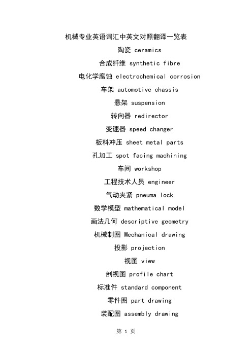
机械专业英语词汇中英文对照翻译一览表陶瓷 ceramics合成纤维 synthetic fibre 电化学腐蚀 electrochemical corrosion车架 automotive chassis悬架 suspension转向器 redirector变速器 speed changer板料冲压 sheet metal parts孔加工 spot facing machining车间 workshop工程技术人员 engineer气动夹紧 pneuma lock数学模型 mathematical model画法几何 descriptive geometry机械制图 Mechanical drawing投影 projection视图 view剖视图 profile chart标准件 standard component零件图 part drawing装配图 assembly drawing尺寸标注 size marking技术要求 technical requirements刚度 rigidity内力 internal force位移 displacement截面 section疲劳极限 fatigue limit断裂 fracture塑性变形 plastic distortion脆性材料 brittleness material刚度准则 rigidity criterion垫圈 washer垫片 spacer直齿圆柱齿轮 straight toothed spur gear 斜齿圆柱齿轮 helical-spur gear直齿锥齿轮 straight bevel gear运动简图 kinematic sketch齿轮齿条 pinion and rack蜗杆蜗轮 worm and worm gear虚约束 passive constraint曲柄 crank摇杆 racker凸轮 cams共轭曲线 conjugate curve范成法 generation method定义域 definitional domain值域 range导数\\微分 differential coefficient求导 derivation定积分 definite integral不定积分 indefinite integral曲率 curvature偏微分 partial differential毛坯 rough游标卡尺 slide caliper千分尺 micrometer calipers攻丝 tap二阶行列式 second order determinant 逆矩阵 inverse matrix线性方程组 linear equations概率 probability随机变量 random variable排列组合 permutation and combination 气体状态方程 equation of state of gas动能 kinetic energy势能 potential energy机械能守恒 conservation of mechanical energy动量 momentum桁架 truss轴线 axes余子式 cofactor逻辑电路 logic circuit触发器 flip-flop脉冲波形 pulse shape数模 digital analogy液压传动机构 fluid drive mechanism机械零件 mechanical parts淬火冷却 quench淬火 hardening回火 tempering调质 hardening and tempering磨粒 abrasive grain结合剂 bonding agent砂轮 grinding wheel后角 clearance angle龙门刨削 planing主轴 spindle主轴箱 headstock卡盘 chuck加工中心 machining center车刀 lathe tool车床 lathe钻削镗削 bore车削 turning磨床 grinder基准 benchmark钳工 locksmith锻 forge压模 stamping焊 weld拉床 broaching machine拉孔 broaching装配 assembling铸造 found流体动力学 fluid dynamics流体力学 fluid mechanics加工 machining液压 hydraulic pressure切线 tangent机电一体化 mechanotronics mechanical-electrical integration气压 air pressure pneumatic pressure稳定性 stability介质 medium液压驱动泵 fluid clutch液压泵 hydraulic pump阀门 valve失效 invalidation强度 intensity载荷 load应力 stress安全系数 safty factor可靠性 reliability螺纹 thread螺旋 helix键 spline销 pin滚动轴承 rolling bearing滑动轴承 sliding bearing弹簧 spring制动器 arrester brake十字结联轴节 crosshead联轴器 coupling链 chain皮带 strap精加工 finish machining粗加工 rough machining变速箱体 gearbox casing腐蚀 rust氧化 oxidation磨损 wear耐用度 durability随机信号 random signal离散信号 discrete signal超声传感器 ultrasonic sensor 集成电路 integrate circuit 挡板 orifice plate残余应力 residual stress套筒 sleeve扭力 torsion冷加工 cold machining电动机 electromotor汽缸 cylinder过盈配合 interference fit热加工 hotwork摄像头 CCD camera倒角 rounding chamfer优化设计 optimal design工业造型设计 industrial moulding design有限元 finite element滚齿 hobbing插齿 gear shaping伺服电机 actuating motor铣床 milling machine钻床 drill machine镗床 boring machine步进电机 stepper motor丝杠 screw rod导轨 lead rail组件 subassembly可编程序逻辑控制器 Programmable Logic Controller PLC 电火花加工 electric spark machining电火花线切割加工 electrical discharge wire - cutting相图 phase diagram热处理 heat treatment固态相变 solid state phase changes有色金属 nonferrous metal陶瓷 ceramics合成纤维 synthetic fibre电化学腐蚀 electrochemical corrosion车架 automotive chassis悬架 suspension转向器 redirector变速器 speed changer板料冲压 sheet metal parts孔加工 spot facing machining车间 workshop工程技术人员 engineer气动夹紧 pneuma lock数学模型 mathematical model画法几何 descriptive geometry机械制图 Mechanical drawing投影 projection视图 view剖视图 profile chart标准件 standard component零件图 part drawing装配图 assembly drawing尺寸标注 size marking技术要求 technical requirements刚度 rigidity内力 internal force位移 displacement截面 section疲劳极限 fatigue limit断裂 fracture塑性变形 plastic distortion脆性材料 brittleness material刚度准则 rigidity criterion垫圈 washer垫片 spacer直齿圆柱齿轮 straight toothed spur gear 斜齿圆柱齿轮 helical-spur gear直齿锥齿轮 straight bevel gear运动简图 kinematic sketch齿轮齿条 pinion and rack蜗杆蜗轮 worm and worm gear虚约束 passive constraint曲柄 crank摇杆 racker凸轮 cams共轭曲线 conjugate curve范成法 generation method定义域 definitional domain值域 range导数\\微分 differential coefficient 求导 derivation定积分 definite integral不定积分 indefinite integral曲率 curvature偏微分 partial differential毛坯 rough游标卡尺 slide caliper千分尺 micrometer calipers攻丝 tap二阶行列式 second order determinant 逆矩阵 inverse matrix线性方程组 linear equations概率 probability随机变量 random variable排列组合 permutation and combination气体状态方程 equation of state of gas动能 kinetic energy势能 potential energy机械能守恒 conservation of mechanical energy 动量 momentum桁架 truss轴线 axes余子式 cofactor逻辑电路 logic circuit触发器 flip-flop脉冲波形 pulse shape数模 digital analogy液压传动机构 fluid drive mechanism机械零件 mechanical parts淬火冷却 quench淬火 hardening回火 tempering调质 hardening and tempering磨粒 abrasive grain结合剂 bonding agent砂轮 grinding wheel Assembly line 组装线Layout 布置图Conveyer 流水线物料板Rivet table 拉钉机Rivet gun 拉钉枪Screw driver 起子Pneumatic screw driver 气动起子worktable 工作桌OOBA 开箱检查fit together 组装在一起fasten 锁紧(螺丝)fixture 夹具(治具)pallet 栈板barcode 条码barcode scanner 条码扫描器fuse together 熔合fuse machine热熔机repair修理operator作业员QC品管supervisor 课长ME 制造工程师MT 制造生技cosmetic inspect 外观检查inner parts inspect 内部检查thumb screw 大头螺丝lbs. inch 镑、英寸EMI gasket 导电条front plate 前板rear plate 后板chassis 基座bezel panel 面板power button 电源按键reset button 重置键Hi-pot test of SPS 高源高压测试Voltage switch of SPS 电源电压接拉键sheet metal parts 冲件plastic parts 塑胶件SOP 制造作业程序material check list 物料检查表work cell 工作间trolley 台车carton 纸箱sub-line 支线left fork 叉车personnel resource department 人力资源部production department生产部门planning department企划部QC Section品管科stamping factory冲压厂painting factory烤漆厂molding factory成型厂common equipment常用设备uncoiler and straightener整平机punching machine 冲床robot机械手hydraulic machine油压机lathe车床planer |plein|刨床miller铣床grinder磨床linear cutting线切割electrical sparkle电火花welder电焊机staker=reviting machine铆合机position职务president董事长general manager总经理special assistant manager特助factory director厂长department director部长deputy manager | =vice manager副理section supervisor课长deputy section supervisor =vice section superisor副课长group leader/supervisor组长line supervisor线长assistant manager助理to move, to carry, to handle搬运be put in storage入库pack packing包装to apply oil擦油to file burr 锉毛刺final inspection终检to connect material接料to reverse material 翻料wet station沾湿台Tiana天那水cleaning cloth抹布to load material上料to unload material卸料to return material/stock to退料scraped |\\'skr?pid|报废scrape ..v.刮;削deficient purchase来料不良manufacture procedure制程deficient manufacturing procedure制程不良oxidation |\\' ksi\\'dei?n|氧化scratch刮伤dents压痕defective upsiding down抽芽不良defective to staking铆合不良embedded lump镶块feeding is not in place送料不到位stamping-missing漏冲production capacity生产力education and training教育与训练proposal improvement提案改善spare parts=buffer备件forklift叉车trailer=long vehicle拖板车compound die合模die locker锁模器pressure plate=plate pinch压板bolt螺栓administration/general affairs dept总务部automatic screwdriver电动启子thickness gauge厚薄规gauge(or jig)治具power wire电源线buzzle蜂鸣器defective product label不良标签identifying sheet list标示单location地点present members出席人员subject主题conclusion结论decision items决议事项responsible department负责单位pre-fixed finishing date预定完成日approved by / checked by / prepared by核准/审核/承办PCE assembly production schedule sheet PCE组装厂生产排配表model机锺work order工令revision版次remark备注production control confirmation生产确认checked by初审approved by核准department部门stock age analysis sheet 库存货龄分析表on-hand inventory现有库存available material良品可使用obsolete material良品已呆滞to be inspected or reworked 待验或重工total合计cause description原因说明part number/ P/N 料号type形态item/group/class类别quality品质prepared by制表 notes说明year-end physical inventory difference analysis sheet 年终盘点差异分析表physical inventory盘点数量physical count quantity帐面数量difference quantity差异量cause analysis原因分析raw materials原料materials物料finished product成品semi-finished product半成品packing materials包材good product/accepted goods/ accepted parts/good parts良品defective product/non-good parts不良品disposed goods处理品warehouse/hub仓库on way location在途仓oversea location海外仓spare parts physical inventory list备品盘点清单spare molds location模具备品仓skid/pallet栈板tox machine自铆机wire EDM线割EDM放电机coil stock卷料sheet stock片料tolerance工差score=groove压线cam block滑块pilot导正筒trim剪外边pierce剪内边drag form压锻差pocket for the punch head挂钩槽slug hole废料孔feature die公母模expansion dwg展开图radius半径shim(wedge)楔子torch-flame cut火焰切割set screw止付螺丝form block折刀stop pin定位销round pierce punch=die button圆冲子shape punch=die insert异形子stock locater block定位块under cut=scrap chopper清角active plate活动板baffle plate挡块cover plate盖板male die公模female die母模groove punch压线冲子air-cushion eject-rod气垫顶杆spring-box eject-plate弹簧箱顶板bushing block衬套insert 入块club car高尔夫球车capability能力parameter参数factor系数phosphate皮膜化成viscosity涂料粘度alkalidipping脱脂main manifold主集流脉bezel斜视规blanking穿落模dejecting顶固模demagnetization去磁;消磁high-speed transmission高速传递heat dissipation热传 rack上料degrease脱脂rinse水洗alkaline etch龄咬desmut剥黑膜D.I. rinse纯水次Chromate铬酸处理Anodize阳性处理seal封孔revision版次part number/P/N料号good products良品scraped products报放心品defective products不良品finished products成品disposed products处理品barcode条码flow chart流程表单assembly组装stamping冲压molding成型spare parts=buffer备品coordinate座标dismantle the die折模auxiliary fuction辅助功能poly-line多义线heater band 加热片thermocouple热电偶sand blasting喷沙grit 砂砾derusting machine除锈机degate打浇口dryer烘干机induction感应induction light感应光response=reaction=interaction感应ram连杆edge finder巡边器concave凸convex凹short射料不足nick缺口speck瑕??shine亮班splay 银纹gas mark焦痕delamination起鳞cold slug冷块blush 导色gouge沟槽;凿槽satin texture段面咬花witness line证示线patent专利grit沙砾granule=peuet=grain细粒grit maker抽粒机cushion缓冲magnalium镁铝合金magnesium镁金metal plate钣金lathe车 mill锉plane刨grind磨drill铝boring镗blinster气泡fillet镶;嵌边through-hole form通孔形式voller pin formality滚针形式cam driver铡楔shank摸柄crank shaft曲柄轴augular offset角度偏差velocity速度production tempo生产进度现状torque扭矩spline=the multiple keys花键quenching淬火tempering回火annealing退火carbonization碳化tungsten high speed steel钨高速的moly high speed steel钼高速的organic solvent有机溶剂bracket小磁导liaison联络单volatile挥发性resistance电阻ion离子titrator滴定仪beacon警示灯coolant冷却液crusher破碎机阿基米德蜗杆 Archimedes worm安全系数 safety factor; factor of safety安全载荷 safe load凹面、凹度 concavity扳手 wrench板簧 flat leaf spring半圆键 woodruff key变形 deformation摆杆 oscillating bar摆动从动件 oscillating follower摆动从动件凸轮机构 cam with oscillating follower 摆动导杆机构 oscillating guide-bar mechanism摆线齿轮 cycloidal gear摆线齿形 cycloidal tooth profile摆线运动规律 cycloidal motion摆线针轮 cycloidal-pin wheel包角 angle of contact保持架 cage背对背安装 back-to-back arrangement背锥 back cone ; normal cone背锥角 back angle背锥距 back cone distance比例尺 scale比热容 specific heat capacity闭式链 closed kinematic chain闭链机构 closed chain mechanism臂部 arm变频器 frequency converters变频调速 frequency control of motor speed变速 speed change变速齿轮 change gear change wheel变位齿轮 modified gear变位系数 modification coefficient标准齿轮 standard gear标准直齿轮 standard spur gear表面质量系数 superficial mass factor表面传热系数 surface coefficient of heat transfer表面粗糙度 surface roughness并联式组合 combination in parallel并联机构 parallel mechanism并联组合机构 parallel combined mechanism 并行工程 concurrent engineering并行设计 concurred design, CD不平衡相位 phase angle of unbalance不平衡 imbalance (or unbalance)不平衡量 amount of unbalance不完全齿轮机构 intermittent gearing波发生器 wave generator波数 number of waves补偿 compensation参数化设计 parameterization design, PD残余应力 residual stress操纵及控制装置 operation control device槽轮 Geneva wheel槽轮机构 Geneva mechanism ; Maltese cross 槽数 Geneva numerate槽凸轮 groove cam侧隙 backlash差动轮系 differential gear train差动螺旋机构 differential screw mechanism差速器 differential常用机构 conventional mechanism; mechanism in common use 车床 lathe承载量系数 bearing capacity factor承载能力 bearing capacity成对安装 paired mounting尺寸系列 dimension series齿槽 tooth space齿槽宽 spacewidth齿侧间隙 backlash齿顶高 addendum齿顶圆 addendum circle齿根高 dedendum齿根圆 dedendum circle齿厚 tooth thickness齿距 circular pitch齿宽 face width齿廓 tooth profile齿廓曲线 tooth curve齿轮 gear齿轮变速箱 speed-changing gear boxes齿轮齿条机构 pinion and rack齿轮插刀 pinion cutter; pinion-shaped shaper cutter 齿轮滚刀 hob ,hobbing cutter齿轮机构 gear齿轮轮坯 blank齿轮传动系 pinion unit齿轮联轴器 gear coupling齿条传动 rack gear齿数 tooth number齿数比 gear ratio齿条 rack齿条插刀 rack cutter; rack-shaped shaper cutter齿形链、无声链 silent chain齿形系数 form factor齿式棘轮机构 tooth ratchet mechanism插齿机 gear shaper重合点 coincident points重合度 contact ratio冲床 punch传动比 transmission ratio, speed ratio传动装置 gearing; transmission gear传动系统 driven system传动角 transmission angle传动轴 transmission shaft串联式组合 combination in series串联式组合机构 series combined mechanism 串级调速 cascade speed control创新 innovation creation创新设计 creation design垂直载荷、法向载荷 normal load唇形橡胶密封 lip rubber seal磁流体轴承 magnetic fluid bearing从动带轮 driven pulley从动件 driven link, follower从动件平底宽度 width of flat-face从动件停歇 follower dwell从动件运动规律 follower motion从动轮 driven gear粗线 bold line粗牙螺纹 coarse thread大齿轮 gear wheel打包机 packer打滑 slipping带传动 belt driving带轮 belt pulley带式制动器 band brake单列轴承 single row bearing单向推力轴承 single-direction thrust bearing单万向联轴节 single universal joint单位矢量 unit vector当量齿轮 equivalent spur gear; virtual gear当量齿数 equivalent teeth number; virtual number of teeth当量摩擦系数 equivalent coefficient of friction当量载荷 equivalent load刀具 cutter导数 derivative倒角 chamfer导热性 conduction of heat导程 lead导程角 lead angle等加等减速运动规律 parabolic motion; constant acceleration and deceleration motion等速运动规律 uniform motion; constant velocity motion等径凸轮 conjugate yoke radial cam等宽凸轮 constant-breadth cam等效构件 equivalent link等效力 equivalent force等效力矩 equivalent moment of force等效量 equivalent等效质量 equivalent mass等效转动惯量 equivalent moment of inertia等效动力学模型 dynamically equivalent model底座 chassis低副 lower pair点划线 chain dotted line(疲劳)点蚀 pitting垫圈 gasket垫片密封 gasket seal碟形弹簧 belleville spring顶隙 bottom clearance定轴轮系 ordinary gear train; gear train with fixed axes 动力学 dynamics动密封 kinematical seal动能 dynamic energy动力粘度 dynamic viscosity动力润滑 dynamic lubrication动平衡 dynamic balance动平衡机 dynamic balancing machine动态特性 dynamic characteristics动态分析设计 dynamic analysis design动压力 dynamic reaction动载荷 dynamic load端面 transverse plane端面参数 transverse parameters端面齿距 transverse circular pitch端面齿廓 transverse tooth profile端面重合度 transverse contact ratio端面模数 transverse module端面压力角 transverse pressure angle锻造 forge对称循环应力 symmetry circulating stress对心滚子从动件 radial (or in-line ) roller follower对心直动从动件 radial (or in-line ) translating follower对心移动从动件 radial reciprocating follower对心曲柄滑块机构 in-line slider-crank (or crank-slider) mechanism 多列轴承 multi-row bearing多楔带 poly V-belt多项式运动规律 polynomial motion多质量转子 rotor with several masses惰轮 idle gear额定寿命 rating life额定载荷 load ratingII 级杆组 dyad发生线 generating line发生面 generating plane法面 normal plane法面参数 normal parameters法面齿距 normal circular pitch法面模数 normal module法面压力角 normal pressure angle法向齿距 normal pitch法向齿廓 normal tooth profile法向直廓蜗杆 straight sided normal worm法向力 normal force反馈式组合 feedback combining反向运动学 inverse ( or backward) kinematics 反转法 kinematic inversion反正切 Arctan范成法 generating cutting仿形法 form cutting方案设计、概念设计 concept design, CD防振装置 shockproof device飞轮 flywheel飞轮矩 moment of flywheel非标准齿轮 nonstandard gear非接触式密封 non-contact seal非周期性速度波动 aperiodic speed fluctuation非圆齿轮 non-circular gear粉末合金 powder metallurgy分度线 reference line; standard pitch line分度圆 reference circle; standard (cutting) pitch circle 分度圆柱导程角 lead angle at reference cylinder分度圆柱螺旋角 helix angle at reference cylinder分母 denominator分子 numerator分度圆锥 reference cone; standard pitch cone分析法 analytical method封闭差动轮系 planetary differential复合铰链 compound hinge复合式组合 compound combining复合轮系 compound (or combined) gear train复合平带 compound flat belt复合应力 combined stress复式螺旋机构 Compound screw mechanism杆组 Assur group干涉 interference刚度系数 stiffness coefficient刚轮 rigid circular spline钢丝软轴 wire soft shaft刚体导引机构 body guidance mechanism 刚性冲击 rigid impulse (shock)刚性转子 rigid rotor刚性轴承 rigid bearing刚性联轴器 rigid coupling高度系列 height series高速带 high speed belt高副 higher pair格拉晓夫定理 Grashoff`s law根切 undercutting公称直径 nominal diameter高度系列 height series功 work工况系数 application factor工艺设计 technological design工作循环图 working cycle diagram工作载荷 external loads工作空间 working space工作应力 working stress工作阻力 effective resistance工作阻力矩 effective resistance moment公法线 common normal line公共约束 general constraint公制齿轮 metric gears功率 power功能分析设计 function analyses design共轭齿廓 conjugate profiles共轭凸轮 conjugate cam构件 link鼓风机 blower固定构件 fixed link; frame固体润滑剂 solid lubricant关节型操作器 jointed manipulator惯性力 inertia force惯性力矩 moment of inertia ,shaking moment 惯性力平衡 balance of shaking force惯性力完全平衡 full balance of shaking force惯性力部分平衡 partial balance of shaking force 惯性主矩 resultant moment of inertia惯性主失 resultant vector of inertia冠轮 crown gear广义机构 generation mechanism广义坐标 generalized coordinate轨迹生成 path generation轨迹发生器 path generator滚刀 hob滚道 raceway滚动体 rolling element滚动轴承 rolling bearing滚动轴承代号 rolling bearing identification code 滚针 needle roller滚针轴承 needle roller bearing滚子 roller滚子轴承 roller bearing滚子半径 radius of roller滚子从动件 roller follower滚子链 roller chain滚子链联轴器 double roller chain coupling滚珠丝杆 ball screw滚柱式单向超越离合器 roller clutch 过度切割 undercutting函数发生器 function generator函数生成 function generation含油轴承 oil bearing耗油量 oil consumption耗油量系数 oil consumption factor 赫兹公式 H. Hertz equation合成弯矩 resultant bending moment 合力 resultant force合力矩 resultant moment of force 黑箱 black box横坐标 abscissa互换性齿轮 interchangeable gears 花键 spline滑键、导键 feather key滑动轴承 sliding bearing滑动率 sliding ratio滑块 slider环面蜗杆 toroid helicoids worm环形弹簧 annular spring缓冲装置 shocks; shock-absorber灰铸铁 grey cast iron回程 return回转体平衡 balance of rotors混合轮系 compound gear train积分 integrate机电一体化系统设计mechanical-electrical integration system design机构 mechanism机构分析 analysis of mechanism机构平衡 balance of mechanism机构学 mechanism机构运动设计 kinematic design of mechanism机构运动简图 kinematic sketch of mechanism机构综合 synthesis of mechanism机构组成 constitution of mechanism机架 frame, fixed link机架变换 kinematic inversion机器 machine机器人 robot机器人操作器 manipulator机器人学 robotics技术过程 technique process技术经济评价 technical and economic evaluation技术系统 technique system机械 machinery机械创新设计 mechanical creation design, MCD机械系统设计 mechanical system design, MSD机械动力分析 dynamic analysis of machinery机械动力设计 dynamic design of machinery机械动力学 dynamics of machinery机械的现代设计 modern machine design机械系统 mechanical system机械利益 mechanical advantage机械平衡 balance of machinery机械手 manipulator机械设计 machine design; mechanical design机械特性 mechanical behavior机械调速 mechanical speed governors机械效率 mechanical efficiency机械原理 theory of machines and mechanisms机械运转不均匀系数 coefficient of speed fluctuation 机械无级变速 mechanical stepless speed changes基础机构 fundamental mechanism基本额定寿命 basic rating life基于实例设计 case-based design,CBD基圆 base circle基圆半径 radius of base circle基圆齿距 base pitch基圆压力角 pressure angle of base circle基圆柱 base cylinder基圆锥 base cone急回机构 quick-return mechanism急回特性 quick-return characteristics急回系数 advance-to return-time ratio急回运动 quick-return motion棘轮 ratchet棘轮机构 ratchet mechanism棘爪 pawl极限位置 extreme (or limiting) position极位夹角 crank angle between extreme (or limiting) positions计算机辅助设计 computer aided design, CAD计算机辅助制造 computer aided manufacturing, CAM计算机集成制造系统 computer integrated manufacturing system, CIMS 计算力矩 factored moment; calculation moment计算弯矩 calculated bending moment加权系数 weighting efficient加速度 acceleration加速度分析 acceleration analysis加速度曲线 acceleration diagram尖点 pointing; cusp尖底从动件 knife-edge follower间隙 backlash间歇运动机构 intermittent motion mechanism 减速比 reduction ratio减速齿轮、减速装置 reduction gear减速器 speed reducer减摩性 anti-friction quality渐开螺旋面 involute helicoid渐开线 involute渐开线齿廓 involute profile渐开线齿轮 involute gear渐开线发生线 generating line of involute 渐开线方程 involute equation渐开线函数 involute function渐开线蜗杆 involute worm渐开线压力角 pressure angle of involute渐开线花键 involute spline简谐运动 simple harmonic motion键 key键槽 keyway交变应力 repeated stress交变载荷 repeated fluctuating load交叉带传动 cross-belt drive交错轴斜齿轮 crossed helical gears胶合 scoring角加速度 angular acceleration角速度 angular velocity角速比 angular velocity ratio角接触球轴承 angular contact ball bearing角接触推力轴承 angular contact thrust bearing 角接触向心轴承 angular contact radial bearing 角接触轴承 angular contact bearing铰链、枢纽 hinge校正平面 correcting plane接触应力 contact stress接触式密封 contact seal阶梯轴 multi-diameter shaft结构 structure结构设计 structural design截面 section节点 pitch point节距 circular pitch; pitch of teeth节线 pitch line节圆 pitch circle节圆齿厚 thickness on pitch circle节圆直径 pitch diameter节圆锥 pitch cone节圆锥角 pitch cone angle解析设计 analytical design紧边 tight-side紧固件 fastener径节 diametral pitch径向 radial direction径向当量动载荷 dynamic equivalent radial load径向当量静载荷 static equivalent radial load径向基本额定动载荷 basic dynamic radial load rating 径向基本额定静载荷 basic static radial load tating 径向接触轴承 radial contact bearing径向平面 radial plane径向游隙 radial internal clearance径向载荷 radial load径向载荷系数 radial load factor径向间隙 clearance静力 static force静平衡 static balance静载荷 static load静密封 static seal局部自由度 passive degree of freedom矩阵 matrix矩形螺纹 square threaded form锯齿形螺纹 buttress thread form矩形牙嵌式离合器 square-jaw positive-contact clutch 绝对尺寸系数 absolute dimensional factor绝对运动 absolute motion绝对速度 absolute velocity均衡装置 load balancing mechanism抗压强度 compression strength开口传动 open-belt drive开式链 open kinematic chain开链机构 open chain mechanism可靠度 degree of reliability可靠性 reliability可靠性设计 reliability design, RD空气弹簧 air spring空间机构 spatial mechanism空间连杆机构 spatial linkage空间凸轮机构 spatial cam空间运动副 spatial kinematic pair空间运动链 spatial kinematic chain空转 idle宽度系列 width series框图 block diagram雷诺方程Reynolds‘s equation离心力 centrifugal force离心应力 centrifugal stress离合器 clutch离心密封 centrifugal seal理论廓线 pitch curve理论啮合线 theoretical line of action隶属度 membership力 force力多边形 force polygon力封闭型凸轮机构 force-drive (or force-closed) cam mechanism 力矩 moment力平衡 equilibrium力偶 couple力偶矩 moment of couple连杆 connecting rod, coupler连杆机构 linkage连杆曲线 coupler-curve连心线 line of centers链 chain链传动装置 chain gearing链轮 sprocket sprocket-wheel sprocket gear chain wheel 联组 V 带 tight-up V belt联轴器 coupling shaft coupling两维凸轮 two-dimensional cam临界转速 critical speed六杆机构 six-bar linkage龙门刨床 double Haas planer轮坯 blank轮系 gear train螺杆 screw螺距 thread pitch螺母 screw nut螺旋锥齿轮 helical bevel gear螺钉 screws螺栓 bolts。
机械专业外文翻译(中英文翻译)

Belt Conveying Systems Development of driving system Among the methods of material conveying employed,beltconveyors play a very important part in the reliablecarrying of material over long distances at competitivecost.Conveyor systems have become larger and more complex and drive systems have also been going through a process of evolution and will continue to do so.Nowadays,bigger belts require more power and have brought the need forlarger individual drives as well as multiple drives such as 3 drives of 750 kW for one belt(this is the case forthe conveyor drives in Chengzhuang Mine).The ability to control drive acceleration torque is critical to beltconveyors’ performance.An efficient drive system should be able to provide smooth,soft starts while maintaining belt tensions within the specified safe limits.For load sharing on multiple drives.torque and speed control are also important considerations in the drive system’sdesign. Due to the advances in conveyor drive controltechnology,at present many more reliable.Cost-effective and performance-driven conveyor drive systems covering a wide range of power are available for customers’choices[1].1 Analysis on conveyor drive technologies1.1 Direct drivesFull-voltage starters.With a full-voltage starter design,the conveyor head shaft is direct-coupled to the motor through the gear drive.Direct full-voltage starters are adequate forrelatively low-power, simple-profile conveyors.With directfu11-voltage starters.no control is provided for various conveyor loads and.depending on the ratio between fu11-and no-1oad power requirements,empty starting times can be three or four times faster than full load.The maintenance-free starting system is simple,low-cost and very reliable.However, they cannot control starting torque and maximum stall torque;therefore.they are limited to the low-power, simple-profile conveyor belt drives.Reduced-voltage starters.As conveyor power requirements increase,controlling the applied motor torque during the acceleration period becomes increasingly important.Because motor torque 1s a function of voltage,motor voltage must be controlled.This can be achieved through reduced-voltage starters by employing a silicon controlled rectifier(SCR).A common starting method with SCR reduced-voltage starters is to apply low voltage initially to take up conveyor belt slack.and then to apply a timed linear ramp up to full voltage and belt speed.However, this starting method will not produce constant conveyor belt acceleration.When acceleration is complete.the SCRs,which control the applied voltage to the electric motor. are locked in full conduction, providingfu11-line voltage to the motor.Motors with higher torque and pull—up torque,can provide better starting torque when combined with the SCR starters, which are available in sizes up to 750 KW.Wound rotor induction motors.Wound rotor induction motors are connected directly to the drive system reducer and are amodified configuration of a standard AC induction motor.By inserting resistance in series with the motor’s rotor windings.the modified motor control system controls motor torque.For conveyor starting,resistance is placed in series with the rotor for low initial torque.As the conveyor accelerates,the resistance is reduced slowly to maintain a constant acceleration torque.On multiple-drive systems.an external slip resistor may be left in series with the rotor windings to aid in load sharing.The motor systems have a relatively simple design.However, the control systems for these can be highly complex,because they are based on computer control of the resistance switching.Today,the majority of control systems are custom designed to meet a conveyor system’s particular specifications.Wound rotor motors are appropriate for systems requiring more than 400 kW .DC motor.DC motors.available from a fraction of thousands of kW ,are designed to deliver constant torque below base speed and constant kW above base speed to the maximum allowable revolutions per minute(r/min).with the majority of conveyor drives, a DC shunt wound motor is used.Wherein the motor’s rotating armature is connected externally.The most common technology for controlling DC drives is a SCR device. which allows for continual variable-speed operation.The DC drive system is mechanically simple, but can include complex custom-designed electronics to monitor and control the complete system.This system option is expensive in comparison to other soft-start systems.but it isa reliable, cost-effective drive in applications in which torque,1oad sharing and variable speed are primary considerations.DC motors generally are used with higher-power conveyors,including complex profile conveyors with multiple-drive systems,booster tripper systems needing belt tension control and conveyors requiring a wide variable-speed range.1.2 Hydrokinetic couplingHydrokinetic couplings,commonly referred to as fluid couplings.are composed of three basic elements; the driven impeller, which acts as a centrifugal pump;the driving hydraulic turbine known as the runner and a casing that encloses the two power components.Hydraulic fluid is pumped from the driven impeller to the driving runner, producing torque at the driven shaft.Because circulating hydraulicfluid produces the torque and speed,no mechanical connection is required between the driving and driven shafts.The power produced by this coupling is based on the circulated fluid’s amount and density and the torque in proportion to input speed.Because the pumping action within the fluid coupling depends on centrifugal forces.the output speed is less than the input speed.Referred to as slip.this normally is between l% and 3%.Basic hydrokinetic couplings are available in configurations from fractional to several thousand kW .Fixed-fill fluid couplings.Fixed-fill fluid couplings are the most commonly used soft-start devices for conveyors with simpler belt profiles and limited convex/concave sections.They are relatively simple,1ow-cost,reliable,maintenance free devices that provide excellent soft starting results to themajority of belt conveyors in use today.Variable-fill drain couplings.Drainable-fluid couplings work on the same principle as fixed-fill couplings.The coupling’s impellers are mounted on the AC motor and the runners on the driven reducer high-speed shaft.Housing mounted to the drive base encloses the working circuit.The coupling’s rotating casing contains bleed-off orifices that continually allow fluid to exit the working circuit into a separate hydraulic reservoir.Oil from the reservoir is pumped through a heat exchanger to a solenoid-operated hydraulic valve that controls the filling of the fluid coupling.To control the starting torque of a single-drive conveyor system,the AC motor current must be monitored to provide feedback to the solenoid control valve.Variable fill drain couplings are used in medium to high-kW conveyor systems and are available in sizes up to thousands of kW .The drives can be mechanically complex and depending on the control parameters.the system can be electronically intricate.The drive system cost is medium to high, depending upon size specified.Hydrokinetic scoop control drive.The scoop control fluid coupling consists of the three standard fluid coupling components:a driven impeller, a driving runner and a casing that encloses the working circuit.The casing is fitted with fixed orifices that bleed a predetermined amount of fluid into a reservoir.When the scoop tube is fully extended into the reservoir, the coupling is l00 percent filled.The scoop tube, extending outside the fluid coupling,is positioned using anelectric actuator to engage the tube from the fully retracted to the fully engaged position.This control provides reasonably smooth acceleration rates.to but the computer-based control system is very complex.Scoop control couplings are applied on conveyors requiring single or multiple drives from l50 kW to 750 kW.1.3 Variable-frequency control(VFC)Variable frequency control is also one of the direct drive methods.The emphasizing discussion about it here is because that it has so unique characteristic and so good performance compared with other driving methods for belt conveyor. VFC devices Provide variable frequency and voltage to the induction motor, resulting in an excellent starting torque and acceleration rate for belt conveyor drives.VFC drives.available from fractional to several thousand(kW ), are electronic controllers that rectify AC line power to DC and,through an inverter, convert DC back to AC with frequency and voltage contro1.VFC drives adopt vector control or direct torque control(DTC)technology,and can adopt different operating speeds according to different loads.VFC drives can make starting or stalling according to any given S-curves.realizing the automatic track for starting or stalling curves.VFC drives provide excellent speed and torque control for starting conveyor belts.and can also be designed to provide load sharing for multiple drives.easily VFC controllers are frequently installed on lower-powered conveyor drives,but when used at the range of medium-high voltage in the past.the structure of VFC controllers becomes verycomplicated due to the limitation of voltage rating of power semiconductor devices,the combination of medium-high voltage drives and variable speed is often solved with low-voltage inverters using step-up transformer at the output,or with multiple low-voltage inverters connected in series.Three-level voltage-fed PWM converter systems are recently showing increasing popularity for multi-megawatt industrial drive applications because of easy voltage sharing between the series devices and improved harmonic quality at the output compared to two-level converter systems With simple series connection of devices.This kind of VFC system with three 750 kW /2.3kV inverters has been successfully installed in ChengZhuang Mine for one 2.7-km long belt conveyor driving system in following the principle of three-level inverter will be discussed in detail.2 Neutral point clamped(NPC)three-level inverter using IGBTsThree-level voltage-fed inverters have recently become more and more popular for higher power drive applications because of their easy voltage sharing features.1ower dv/dt per switching for each of the devices,and superior harmonic quality at the output.The availability of HV-IGBTs has led to the design of a new range of medium-high voltage inverter using three-level NPC topology.This kind of inverter can realize a whole range with a voltage rating from 2.3 kV to 4.1 6 kV Series connection of HV-IGBT modules is used in the 3.3 kV and 4.1 6 kV devices.The 2.3 kV inverters need only one HV-IGBT per switch[2,3].2.1 Power sectionTo meet the demands for medium voltage applications.a three-level neutral point clamped inverter realizes the power section.In comparison to a two-level inverter.the NPC inverter offers the benefit that three voltage levels can be supplied to the output terminals,so for the same output current quality,only 1/4 of the switching frequency is necessary.Moreover the voltage ratings of the switches in NPC inverter topology will be reduced to 1/2.and the additional transient voltage stress on the motor can also be reduced to 1/2 compared to that of a two-level inverter.The switching states of a three-level inverter are summarized in Table 1.U.V and W denote each of the three phases respectively;P N and O are the dc bus points.The phase U,for example,is in state P(positive bus voltage)when the switches S1u and S2u are closed,whereas it is in state N (negative bus voltage) when the switches S3u and S4u are closed.At neutral point clamping,the phase is in O state when either S2u or S3u conducts depending on positive or negative phase current polarity,respectively.For neutral point voltage balancing,the average current injected at O should be zero.2.2 Line side converterFor standard applications.a l2-pulse diode rectifier feeds the divided DC-link capacitor.This topology introduces low harmonics on the line side.For even higher requirements a 24-pulse diode rectifier can be used as an input converter.For more advanced applications where regeneration capability is necessary, an active front.end converter can replace thediode rectifier, using the same structure as the inverter.2.3 Inverter controlMotor Contro1.Motor control of induction machines is realized by using a rotor flux.oriented vector controller.Fig.2 shows the block diagram of indirect vector controlled drive that incorporates both constant torque and high speed field-weakening regions where the PW M modulator was used.In this figure,the command fluxis generated as function of speed.The feedback speed is added with the feed forward slip command signal. the resulting frequency signal is integrated and thenthe unit vector signals(cosand sin)are generated.The vector rotator generates the voltageand anglecommands for the PW M as shown.PWM Modulator.The demanded voltage vector is generated using an elaborate PWM modulator.The modulator extends the concepts of space-vector modulation to the three-level inverter.The operation can be explained by starting from a regularly sampled sine-triangle comparison from two-level inverter.Instead of using one set of reference waveforms and one triangle defining the switching frequency, the three-level modulator uses two sets of reference waveforms U r1 and U r2 and just one triangle.Thus, each switching transition isused in an optimal way so that several objectives are reached at the same time.Very low harmonics are generated.The switching frequency is low and thus switching losses are minimized.As in a two-level inverter, a zero-sequence component can be added to each set of reference waveform s in order to maximize the fundamental voltage component.As an additional degree of freedom,the position of the reference waveform s within the triangle can be changed.This can be used for current balance in the two halves of the DC-1ink.3 Testing resultsAfter Successful installation of three 750 kW /2.3 kV three-level inverters for one 2.7 km long belt conveyor driving system in Chengzhuang Mine.The performance of the whole VFC system was tested.Fig.3 is taken from the test,which shows the excellent characteristic of the belt conveyor driving system with VFC controller.Fig.3 includes four curves.The curve 1 shows the belt tension.From the curve it can be find that the fluctuation range of the belt tension is very smal1.Curve 2 and curve 3 indicate current and torque separately.Curve 4 shows the velocity of the controlled belt.The belt velocity havethe“s”shape characteristic.A1l the results of the test showa very satisfied characteristic for belt driving system.4 ConclusionsAdvances in conveyor drive control technology in recent years have resulted in many more reliable.Cost-effective and performance-driven conveyor drive system choices for users.Among these choices,the Variable frequency control (VFC) method shows promising use in the future for long distancebelt conveyor drives due to its excellent performances.The NPC three-level inverter using high voltage IGBTs make the Variable frequency control in medium voltage applications become much more simple because the inverter itself can provide the medium voltage needed at the motor terminals,thus eliminating the step-up transformer in most applications in the past.The testing results taken from the VFC control system with NPC three.1evel inverters used in a 2.7 km long belt conveyor drives in Chengzhuang Mine indicates that the performance of NPC three-level inverter using HV-IGBTs together with the control strategy of rotor field-oriented vector control for induction motor drive is excellent for belt conveyor driving system.中文译文:带式输送机及其牵引系统在运送大量的物料时,带式输送机在长距离的运输中起到了非常重要的竞争作用。
机械外文翻译中英文
附录英文原文N/C Machine Tool ElementN/C machine tool elements consist of dimensioning systems, controlsystems,servomechanisms and open-orclosed-loop systems. It is important to understand each elementprior to actual programming of a numerically controlled port.The term measuring system in N/C refers to the method a machine tool uses to move a partfrom a reference point to a target point. A target point may be a certain locating for drilling a hole,milling a slot, or other machine operation. The two measuring systems used on N/C machines arethe absolute and incremental. The absolute measuring system uses a fixed reference point. It ison this point that all positional information is based. In other words, all the locations to which apart will be moved must be given dimensions relating to that original fixed reference point.Figure shows an absolute measuring system with X and Y dimensions, each based on the origin.The incremental measuring system has a floating coordinating system. With the incrementalsystem, the time the part is moved. Figure 16.2 show X and Y values using an incrementalmeasuring system. Notice that with this system, each new location bases its values in X and Yfrom the preceding location. One disadvantage to this system is that any errors made will berepeated throughout the entire program, if not detected and corrected.There are two types of control systems commonly used on N/C equipment: point-to-point andcontinuous path. A point-to-point controlled N/C machine tool, sometimes referred to as apositioning control type, has the capability of moving only along a straight line. However, whentwo axes are programmed simultaneously with equal values a 45 angle will be generated.Point-to-point systems are generally found on drilling and simple milling machine where holelocation and straight milling jobs are performed. Point-to-point systems can be utilized togenetate arcs and angles by programming the machine to move in a series of small steps. Usingthis technique, however, the actual path machined is slightly different from the cutting pathspecified.Machine tools that have the capability of moving simultaneously in two or more axes areclassified as continuous-path or contouring. These machines are used for machining arcs, radii,circles, and angles of any size in two or there dimensions. Continuous-path machines aremoreexpensive than point-to-point systems and generally require a computer to aid programming when machining complex contours.N/C servomechanisms are devices used for producing accurate movement of a table or slid along an axis. Two types of servos are commonly used on N/C equipment: electric stepping motors and hydraulic motors. Stepping motor servos are frequently used on less expensive N/C equipment. These motors are generally high-torque power servos and mounted directly to a lead screw of a table or tool slide. Most stepping motors are actuated by magnetic pulses from the stator and rotor assemblies. The net result of this action is that one rotation of the motor shaft produces 200 steps. Connection the motor shaft to a 10-pitch lead screw allows 0.0005-in. movements to be made. Hydraulic servos produce a fluid pressure that flows through gears or pistons to effect shaft rotation. Mechanical motion of lead screws and slides is accomplished through various values and controls from these hydraulic motors. However, they are more expensive and noisy. Most larger N/C machines use hydraulic servos.N/C machines that use an open-loop system contain no-feedback signal to ensure that a machine axis has traveled the required distance. That is, if the input received was to move a particular table axis 1.000 in, the servo unit generally moves the table 1.000 in. There is no means for comparing the actual table movement with the input signal, howeve r, The only assurance that the table has actually moved 1.000 in. is the reliability of the servo system used.Open-loop systems are, of course, less expensive than closed-loop systems. A closed-loop system compares the actual output with the input signal and compensates for any errors. A feedback unit actually compares the amount the table has been moved with the input signal. Some feedback units used on closed-loop systems are transducers, electrical or magnetic scales, and synchros. Closed-loop systems greatly increase the reliability of N/C machines. Machining Centers Many of today’s more sophisticated lathes are called machining centers since they are capable of performing, in addition to the normal turning operations, certain milling and drilling operations. Basically, a machining center can be thought of as being a combination turret lathe and milling machine. Additional features are sometimes included by manufacturers to increase the versatility of their machines.Numerical ControlOne of the most fundamental concepts in the area of advanced manufacturing technologies is numerical control (NC). Prior to the advent of NC, all machine tools were manually operated and controlled .Among the many limitations associated with manual control machine tools, perhaps none is more prominent than the limitation of operator skills. With manual control, the quality of the product is directly related to and limited to the skills of the operator. Numerical control represents the first major step away from human control of machine tools.Numerical control means the control of machine tools and other manufacturing systems through the use of prerecorded, written symbolic instructions. Rather than operating a machine tool, an NC technician writes a program that issues operational instructions to the machine tool. For a machine tool to be numerically controlled, it must be interfaced with a device for accepting and decoding the programmed instructions, known as a reader.Numerical control was developed to overcome the limitation of human operators, and it has done so. Numerical control machines are more accurate than manually operated machines, they can produce parts more uniformly, they are faster, and the long-run tooling costs are lower. The development of NC led to the development of several other innovations in manufacturing technology:1. Electrical discharge machining.2. Laser cutting.3. Electron beam welding.Numerical control has also made machine tools more versatile than their manually operated predecessors. An NC machine tool can automatically produce a wide variety of parts, each involving an assortment of widely varied and complex machining processes. Numerical control has allowed manufacturers to undertake the production of products that would not have been feasible from an economic perspective using manually controlled machine tools and processes. Like so many advanced technologies, NC was born in the laboratories of the Massachusetts Institute of Technology. The concept of NC was developed in the early 1950s with funding provided by the U. S. Air force. In its earliest stages, NC machines were able to make straight cuts efficiently and effectively.However, curved paths were a problem because the machine tool had to be programmed to undertake a series of horizontal and vertical steps to produce a curve. The shorter is the straight lines making up the steps, the smoother is the curve. Each line segment in the steps had to be calculated.This problem led to the development in 1959 of the Automatically Programmed Too ls (APT) language. This is a special programming language for NC that uses statements similar to English language to define the part geometry, describe the cutting tool configuration, and specify the necessary motions. The development of the APT language was a major step forward in the further development of NC technology. The original NC systems were vastly different from those used today. The machines had hardwired logic circuits. The instructional programs were written on punched paper, which was later to be replaced by magnetic plastic tape. A tape reader was used to interpret the instructions written on the tape for the machine. Together, all of this represented a giant step forward in the control of machine tools. However, there were a numberof problems with NC at this point in its development.A major problem was the fragility of the punched paper tape medium. It was common for the paper tape containing the programmed instructions to break or tear during a machining process. This problem was exacerbated by the fact that each successive time a part was produced on a machine tool, the paper tape carrying the programmed instructions had to be rerun through the reader. If it was necessary to produce 100 copies of a given part, it was also necessary to run the paper tape through the reader 100 separate times. Fragile paper tapes simply could not withstand the rigors of a shop floor environment and this kind of repeated use.This led to the development of a special magnetic plastic tape. Whereas the paper tape carried the programmed instructions as a series of holes punched in the tape, the plastic tape carried the instructions as a series of holes punched in the tape, the plastic tape carried the instructions as a series of magnetic dots. The plastic tape was much stronger than the paper taps, which solved the problem of frequent tearing and breakage. However, it still left two other problems.The most important of these was that it was difficult or impossible to change the instructions entered on the tape. To make even the most minor adjustments in a program of instructions, it was necessary to interrupt machining operations and make a new tape .It was also still necessary to run the tape through the reader as many times as there were parts to be produced. Fortunately, computer technology became a reality and soon solved the problems of NC associated with punched paper and plastic tape.The development of a concept known as direct numerical control (DNC) solved the paper and plastic tape problems associated with numerical control by simply eliminating tape as the medium for carrying the programmed instructions. In direct numerical control .machine tools are tied, via a data transmission link, to a host computer. Programs for operating the machine tools are stored in the host computer and fed to the machine tool as needed via the data transmission linkage. Direct numerical control represented a major step forward over punched tape and plastic tape. However, it is subject to the same limitations as all technologies that depend on a host computer. When the lost computer goes down, the machine tools also experience downtime. This problem led to the development of computer numerical control.The development of the microprocessor allowed for the development of programmable logic controllers (PLCs) and microcomputers. These two technologies allowed for the development of computer numerical control (CNC).With CNC, each machine tool has a PLC or a microcomputer that serves the same purpose. This allows programs to be input and stored at each individual machine tool. It also allows programs to be developed off-line and downloaded at the individual machine tool. CNC solved the problems associated with downtime of the hostcomputer, but it introduced another known as data management. The same program might be loaded on ten different microcomputers with no communication among them. This problem is in the process of being solved by local area networks that connect microcomputers for better data management. Cutting Tool GeometryShape of cutting tools, particularly the angles, and tool material are very important factors. Angles determine greatly not only tool life but finish quality as well. General principles upon which cutting tool angles are based do not depend on the particular tool, Basically, the same considerations hold true whether a lathe tool, a milling cutter, a drill, or even a grinding wheel are being designed. Since, however the lathe tool, depicted in Fig. 18.1, might be easiest to visualize, its geometry is discussed.Tool features have been identified by many names. The technical literature is full of confusing terminology. Thus in the attempt to cleat up existing disorganized conceptions and nomenclature, this American Society of Mechanical Engineers published AS A Standard B5-22-1950. What follows is based on it.A single-point tool is a cutting tool having one face and one continuous cutting edge, Tool angles identified in Fig. 18.2 are as follows:Tool angle 1, on front view, is the back-rank angle. It is the angle between the tool face and a line parallel to the tool base of the shank in a longitudinal plane perpendicular to the tool base. When this angle is downward from front to rear of the cutting edge, the rake is positive; when upward from front to black, the rake is negative. This angle is most significant in the machining process, because it directly affects the cutting force, finish, and tool life.The side-rake angle, numbered 2, measures the slope of the face on a cross plane perpendicular to the tool base. It, also, is an important angle, because it directs chip flow to the side of the tool post and permits the tool to feed more easily into the work.The end-relief angle is measured between a line perpendicular to the base and the end flank immediately below the end cutting edge; it is numbered 3 in the figure. It provides clearance between work and tool so that its cut surface can flow by with minimum rubbing against the tool. To save time, a portion of the end flank of the tool may sometimes be lest unground, having been previously forged to size. In such case, this end-clearance angle, numbered 4, measured to the end flank surface below the ground portion, would be larger than the relief angle.Often the end cutting edge is oblique to the flank. The relief angle is then best measured in a plane normal to the end cutting edge angle. Relief is also expressed as viewed from side and end of the tool.The side-relief angle, indicated as 5, is measured between the side flank, just below thecutting edge, and a line through the cutting edge perpendicular to the base of the tool. This clearance permits the tool to advance more smoothly into the work.Angle 6 is the end-cutting-edge angle measured between the end cutting edge and a line perpendicular to the side of the tool shank. This angle prevents rubbing of the cut surface and permits longer tool file.The side-cutting-edge angle, numbered 7, is the angle between the side cutting edge and the side of the tool shank. The true length of cut is along this edge. Thus the angel determines the distribution of the cutting forces. The greater the angle, the longer the tool life; but the possibility of charter increases. A compromise must, as usual, be reached.The nose angle, number 8, is the angle between the two component cutting edges. If the corner is rounded off, the arc size is defined by the nose radius 9. The radius size influences finish and chatter.Sand CastingThe first stage in the production of sand castings must be the design and manufacture of a suitable pattern. Casting patterns are generally made from hard word and the pattern has to be made larger than the finished casting size to allow for the shrinkage that takes place during solidification and cooling. The extent of this shrinkage varies with the type of metal or alloy to be cast. For all but the simplest shapes the pattern will be made in two or more pieces to facilitate moulding. If a hollow casting is to be made the pattern design will include extension pieces so that spaces to accept the sand core are moulded into sand. These additional spaces in the mould are termed core prints.Sand moulds for the production of small and medium-sized castings are made in a moulding box. The mould is made in two or more parts in order that the pattern may be removed.The drag half of the mould box is placed on a flat firm board and the drag half of the pattern placed in position. Facing sand is sprinkled over the pattern and then the mould box is filled with moulding sand. The sand is rammed firmly around the pattern. This process of filling and ramming may be done by hand but mould production is automated in a large foundry with the mould boxes moving along a conveyor, firstly to be filled with sand from hoppers and then to pass under mechanical hammers for ramming. When ramming of the sand is complete, excess sand is removed to leave a smooth surface flush with the edges of the moulding box.The completed drag is now turned over and the upper, or cope, portion of the moulding box positioned over it. The cope half of the pattern is placed in position, correct alignment being ensured by means of small dowel pins. Patterns for the necessary feeder, runner and risers are also placed so as to give an even distribution of metal into the mould cavity. The rise rs should coincide with the highest readily escape from the mould. The sizes of risers should be such thatthe metal in them does not freeze too rapidly. An important function of a riser is to act as reservoir of liquid metal to feed solidification within the mould. A thin coating of dry parting sand is sprinkled into mould at this stage. This is to prevent the cope and drag sticking together when the cope half is moulded. The cope is now filled with moulding sand and this is rammed firmly into shape in the same manner as in the making of the drag.After the ramming of sand in the cope is completed the two halves of the moulding box are carefully separated. At this stage venting of the moulding box are carefully separated. At this stage venting of the mould can be done, if necessary, to increase the permeability of the mould. After venting the patterns are carefully removed from both cope and drag, and a gate or gates are carefully cut to connect the runner channel with the main cavity. Gates should be sited to allow or entry into mould with a minimum of turbulence. Any loose sand is gently blown away and if a core is to be used it the cope upon the drag and it is then ready for use. Liquid metal is poured smoothly into the mould via the feeder. Pouring ceases when liquid metal appears at the top of the risers and the feeder channel is also full.When the metal that has been poured into a sand mould has fully solidified the mould is broken and casting is removed. The casting still has the runner and risers attached to it and there will be sand adhering to portions of the surface. Runners and risers are cut off and returned to the melting furnace. Sand cores are broken and adherent sand is cleaned from the surface by vibration or by sand blasting with dry sand. Any fins or metal flash formed at mould parting lines are removed by grinding and the castings are then ready for inspection.The main Elements of Horizontal Milling MachinesColumn and base The column and base form the foundation of the complete machine. Both are made from cast iron, designed with thick sections to ensure complete rigidity and freedom form vibration. The base, upon which the column is mounted, is also the cutting-fluid reservoir and contains the pump to circulate the fluid to cutting area.The column contains the spindle, accurately located in precision bearings. The spindle id driven through a gearbox from a vee-belt drive from the electric motor housed at the base of column. The gearbox enables a range of spindle speeds to be selected. In the model shown, twelve spindle speeds from 32 to 1400rev/min are available. The front of column carries the guideways upon which the knee is located and guided in a vertical direction.KneeThe knee, mounted on the column guideways, provides the vertical movement of the table. Power feed is available, through a gearbox mounted on the side, from a separate built-in motor, providing a range of twelve feed rates from 6 to 250mm/min. Drive is through a leadscrew, whose bottom end is fixed to machine base. Provision is made to raise and lower the knee byhand through a leadscrew and nut operates by a handwheel at the front. The knee has guideways on its top surface giving full-width support to the saddle and guiding it in a transverse direction. lock is provided to clamp the knee in any vertical position on the column.SaddleThe saddle, mounted on the knee guideways, providers the transverse movement of the table. Power feed is provided through the gearbox on the knee. A range of twelve feeds is available, from 12 to 500mm/min. Alternative hand movement is provided through a leadscrew and nut by a hand heel at the front of the knee.Camping of saddle to the knee is achieved by two clamps on the side of the saddle.The saddle has dovetail gun its upper surface, at right angles to the knee guideways, to provide a guide to the table in a longitudinal direction.TableThe table provides the surface upon which all workpieces and workholding equipment are located and clamped. A series of tee slots is provided for this purpose. The dovetail guides on undersurface locate in the guideways on the saddle, giving straight-line movement to the table in longitudinal direction at right angles to the saddle movement.Power feed is provided from the knee gearbox, through the saddle, to the table leadscrew. Alternative hand feed is provided by a handwheel at each end of the table. Stops at the front of the table can be set to disengage the longitudinal feed automatically in each direction. Spindle The spindle, accurately mounted in precision bearings, provides the drive for the milling cutters. Cutters can be mounted straight on the spindle nose or in curter-holding devices which in turn are mounted in the spindle, held in position by a drawbolt passing the hold spindle. Spindles of milling machines have a standard spindle nose to allow for easy interchange of cutters and cutter-holding devices. The bore of the nose is tapered to provide accurate location, the angle of taper being 1. The diameter of the taper depends on the size of the machine and may be 30,40,or 50 IST. Due to their steepness of angle, there tapers –known as non-stick or self-releasing- cannot be relied upon to transmit the drive to the cutter or cutter-holding device. Two driving keys are provided to transmit the drive.Overarm and arbor supportDue to the length of arbors used, support is required at the outer end to prevent deflection when cutting takes place. Support is provided by an arbor-support bracket, clamped to an overarm which is mounted on top of the column in a dovetail slide. The overarm is adjustable in or out for different lengths of arbor, or can be fully pushed in when arbor support is not required. Two clamping bolts are support is located in the overarm dovetail and is locked by which the arbor runs during splindle rotation.中文译文数控机床的组成部分数控机床的组成部分包括测量系统、控制系统、伺服系统及开环或闭环系统,在对数控零件进行实际程序设计之前,了解各组成部分是重要的。
- 1、下载文档前请自行甄别文档内容的完整性,平台不提供额外的编辑、内容补充、找答案等附加服务。
- 2、"仅部分预览"的文档,不可在线预览部分如存在完整性等问题,可反馈申请退款(可完整预览的文档不适用该条件!)。
- 3、如文档侵犯您的权益,请联系客服反馈,我们会尽快为您处理(人工客服工作时间:9:00-18:30)。
英文资料Limits and TolerancesThe breakage of the machine spare parts ,generally always from the surface layer beginning of .The function of the product ,particularly its credibility and durable ,be decided by the quantity of spare parts surface layer to a large extent. Purpose that studies the machine to process the surface quantity be for control the machine process medium various craft factor to process the surface quantity influence of regulation, in order to make use of these regulations to control to process the process, end attain to improve the surface quantity, the exaltation product use the function of purpose .The machine processes the surface quantity to use the influence of the function to the machine(A) The surface quantity to bear to whet the sexual influence1.Rough degree of surface to bear to whet the sexual influenceA just process vice-of two contact surfaces of good friction, the first stage is rough only in the surface of the peak department contact ,the actual contact area is much smaller than theoretical contact area, in contact with each other the peak of the units have very great stress, to produce actual contact with the surface area of plastic deformation, deformation and peak between the Department of shear failure, causing serious wear.Parts wear may generally be divided into three stages, the initial stage of wear and tear, normal wear and tear all of a sudden intense phase of stage wear.Parts of the surface roughness of the surface wear big impact. In general the smaller the value of surface roughness, wear better. However, surface roughness value is too small, lubricants difficult to store, contact between the adhesive-prone elements, wear it to increase. Therefore, the surface roughness of a best value, the value and parts of the work related to increased work load, the initial wear increased, the best rough surface is also increased.2.Cold Working hardening the surface of the wear resistanceProcessing the Cold Work hardening the surface of the friction surface layer of metal microhardness increase, it will generally improve the wear resistance. Cold Working but not a higher degree of hardening, wear resistance for the better, because too much will lead to hardening of the Cold Working excessive loose organization ofmetal, even a crack and peeling off the surface of the metal, declined to wear resistance.(B)The surface quality of the impact of fatigue strengthMetal hand alternating loads of fatigue after the damage occurred in parts often Chilled layer below the surface and, therefore parts of the surface quality of fatigue very influential.1.Surface roughness on the impact of fatigue strengthIn alternating load, the surface roughness of the Au-site easily lead to stress concentration, a fatigue crack, the higher the value of surface roughness, surface traces of Yu Shen Wen, Wen at the end of the radius smaller, anti-fatigue damage at the end of the more capacity Worse.2.Residual stress, fatigue Cold Work hardening of the impactResidual stress on the impact of large parts fatigue. Surface layer of residual stress fatigue crack will expand and accelerate the fatigue damage the surface layer and the residual stress can prevent fatigue crack growth, delaying the formation of fatigue damage.(C)The surface quality of the corrosion resistance of the impactParts of the corrosion resistance to a large extent depends on the surface roughness. The higher the value of surface roughness, Au Valley accumulate on the more corrosive substances. Corrosion resistance of the more worse.Surface layer of residual stress will produce stress corrosion cracking, lower parts of the wear-resistance, and the residual stress is to prevent stress corrosion cracking.(D) The surface quality with qualityRough surface will affect the value of the size of the co-ordination with the surface quality. The gap with rough value will increase wear and tear, increased space, with the requirements of the destruction of nature. For Fit, the assembly part of the process of convex surface-crowded peak times, the actual reduction of the surplus and reduce the support of the connection between the strength.DimensioningThe design of a machine includes many factors other than those of determining the loads and stresses and selecting the proper materials. Before construction or manufacture can begin, it is necessary to have complete assembly and detail drawings to convey all necessary information to the shop men. The designer frequently is called upon to check the drawings before they are sent to the shop. Much experience andfamiliarity with manufacturing processes are needed before one can become conversant with all phases of production drawings.Drawings should be carefully checked to see that the dimensioning is done in a manner that will be most convenient and understandable to the production departments. It is obvious that a drawing should be made in such a way that it has one and only one interpretation. In particular, shop personnel should not be required to make trigonometric or other involved calculations before the production machines can be set up.Dimensioning is an involved subject and long experience is required for its mastery.Tolerances must be placed on the dimensions of a drawing to limit the permissible variations in size because it is impossible to manufacture a part exactly to a given dimension. Although small tolerances give higher quality work and a better operating mechanism, the cost of manufacture increases rapidly as the tolerances are reduced, as indicated by the typical curve of Fig 14.1. It is therefore important that the tolerances be specified at the largest values that the operating or functional considerations permit.Tolerances may be either unilateral or bilateral. In unilateral dimensioning, one tolerance is zero, and all the variations are given by the other tolerance. In bilateral dimensioning, a mean dimension is used which extends to the midpoint of the tolerance zone with equal plus and minus variations extending each way from this dimension.The development of production processes for large-volume manufacture at low cost has been largely dependent upon interchangeability of component parts. Thus the designer must determine both the proper tolerances for the individual parts, The manner of placing tolerances on drawings depends somewhat on the kind of product or type of manufacturing process. If the tolerance on a dimension is not specifically stated, the drawing should contain a blanket note which gives the value of the tolerance for such dimensions. However, some companies do not use blanket notes on the supposition that if each dimension is considered individually, wider tolerance than those called for in the note could probably be specified. In any event it is very important that a drawing be free from ambiguities and be subject only to a single interpretation.Dimension and ToleranceIn dimensioning a drawing, the numbers placed in the dimension lines represent dimension that are only approximate and do not represent any degree of accuracy unless so stated by the designer.To specify a degree of accuracy, it is necessary to add tolerance figures to the dimension. Tolerance is the amount of variation permitted in the part or the total variation allowed in a given dimension. A shaft might have a nominal size of 2.5 in. (63.5mm), but for practical reasons this figure could not be maintained in manufacturing without great cost. Hence, a certain tolerance would be added and , if a variation of ±0.003 in.(±0.08mm) could be permitted, the dimension would be stated 2.500±0.003(63.5±0.008mm).Dimensions given close tolerances mean that the part must fit properly with some other part. Both must be given tolerances in keeping with the allowance desired, the manufacturing processes available, and the minimum cost of production and assembly that will maximize profit. Generally speaking, the cost of a part goes up as the tolerance is decreased. If a part has several or more surfaces to be machined, the cost can be excessive when little deviation is allowed from the nominal size.Allowance, which is sometimes confused with tolerance, has an altogether different meaning.It is the minimum clearance space intended between mating parts and representsthe condition of tightest permissible fit. If a shaft, size 1.4980.0000.003+-, is to fit a hole ofsize 1.5000.0030.000+-, the minimum size hole is 1.500 and the maximum size shaft is 1.498.Thus the allowance is 0.002 and the maximum clearance is 0.008 as based on the minimum shaft size and maximum hole dimension.Tolerances may be either unilateral or bilateral. Unilateral tolerance means that any variation is made in only one direction from the nominal or basic dimension.Referring to the previous example, the hole is dimensioned 1.5000.0030.000+-, whichrepresents a unilateral tolerance. If the dimensions were given as 1.500±0.003, the tolerance would be bilateral; that is , it would vary both over and under the nominal dimension. The unilateral system permits changing the tolerance while still retaining the same allowance or type of fit. With the bilateral system, this is not possible without also changing the nominal size dimension of one or both of the two mating parts. In mass production, where mating parts must be interchangeable, unilateral tolerances are customary. To have an interference or fore fit between mating parts, the tolerances must be such as to create a zero or negative allowance.Tolerances Limits and FitsThe drawing must be a true and complete statement of the designer’s expr essed in such a way that the part is convenient to manufacture. Every dimension necessary to define the product must be stated once and repeated in different views. Dimensions relating to one particular feature, such as the position and size of hole, where possible, appear on the same view.There should be no more dimensions than are absolutely necessary, and no feature should be located by more than one dimension in any direction. It may be necessary occasionally to give an auxiliary dimension for reference, possibly for inspection. When this is so, the dimension should be enclosed in a bracket and marked for reference. Such dimensions are not governed by general tolerances.Dimensions that affect the function of the part should always be specified and not left as the sum or other dimensions. If this is not done, the total permissible variation on that dimension will form the sum or difference of the other dimensions and their tolerance, and this with result in these tolerances having to be made unnecessarily tight. The overall dimension should always appear.All dimensions must be governed by the general tolerance on the drawing unless otherwise stated. Usually, such a tolerance will be governed by the magnitude of the dimension. Specific tolerances must always be stated on dimensions affecting or interchangeability.A system of tolerances is necessary to allow for the variations in accuracy that are bound to occur during manufacture, and still provide for interchangeability and correct function of the part.A tolerance is the difference in a dimension in order to allow for unavoidable imperfections in workmanship. The tolerance range will depend on the accuracy of the manufacturing organization, the machining process and the magnitude of the dimension. The greater the tolerance range is disposed on both sides of the nominal dimension. A unilateral tolerance is one where the tolerance zone is on one side only of the nominal dimension, in which case the nominal dimension may from one of the limits.Limits are the extreme dimensions of the tolerance zone. For example, nominal dimension30mm tolerance 30.0230.000++ limits 30.02530.000Fits depend on the relationship between the tolerance zones of two mating parts,and may be broadly classified into a clearance fit with positive allowance, a transition fit where the allowance may be either positive or negative (clearance or interference) , an interference fit where the allowance is always negative.Type of Limits and FitsThe ISO system of Limits and Fits, widely used in a number of leading metric countries, is considerably more complex than the ANSI system.In this system, each part has a basic size. Each limit of part, high and sign being obtained by subtracting the basic size form the limit in question. The difference between the two limits of size of a part is called the tolerance, an absolute without sign.There are three classes of fits: 1) clearance fits, 2) transition fits ( the assembly may have either clearance or interference ), and 3) interference fits .Either a shaft-basis system or a hole-basis system may be used. For any given basic size, a range of tolerance and deviations may be specified with respect to be line of zero deviation, called the zero line. The tolerance is a function of the basic size and is designated by a number symbol, called the grade-thus the tolerance grade. The position of the tolerance with respect to the zero line also a function of the basic size-is indicated by a letter symbol(or two letter), a capital letter for holes and a lowercase letter for shafts. Thus the specification for a hole and shaft having a basic size of 45mm might be45H8/g7.Twenty standard grades of tolerance are provided, called IT 01,IT 0 ,IT 1-18, providing numerical values for each nominal diameter, in arbitrary steps up to 500mm (for example 0-3,3-6,6-10…, 400-500mm). The value of the tolerance unit, I, for grades 5-16 is=+0.0.001i DWhere i is in microns and D in millimeters.Standard shaft and hole deviations similarly are provided by sets of formulas, However, for practical, both tolerances and deviations are provided in three sets of rather complex tables. Additional tables gives the values for basic sizes above 500mm and for “Commonly Used Shafts and Holes” in two categories ---“General Purpose” and “Fine Mecbanisms and Horology”.中文翻译极限与误差机械零件的破坏,一般总是从表层开始的。