中英文翻译-机械类-机械设计-外文翻译
机械学英语

机械学英语
机械学(Mechanical Engineering)涉及广泛的工程领域,涵盖机械设计、制造、材料、热力学、控制等多个方面。
以下是一些常见的机械学英语术语及其解释:
1. Mechanical Engineering - 机械工程
2. Thermodynamics - 热力学
3. Fluid Mechanics - 流体力学
4. Mechanics - 力学
5. Materials Science - 材料科学
6. Manufacturing Processes - 制造工艺
7. Control Systems - 控制系统
8. Robotics - 机器人技术
9. Kinematics - 运动学
10. Dynamics - 动力学
11. Statics - 静力学
12. Heat Transfer - 热传导
13. Machine Design - 机械设计
14. CAD/CAM - 计算机辅助设计/计算机辅助制造
15. Vibration Analysis - 振动分析
16. Finite Element Analysis (FEA) - 有限元分析
17. Hydraulics - 液压学
18. Pneumatics - 气动学
19. Turbomachinery - 涡轮机械
20. Engineering Drawing - 工程制图
这些术语是在机械工程领域中常见的英语专业术语,涵盖了机械工程学科的各个方面。
深入学习这些术语可以帮助理解和掌握机械工程相关的知识和技术。
机械毕业设计英文外文翻译300拉臂式垃圾车设计
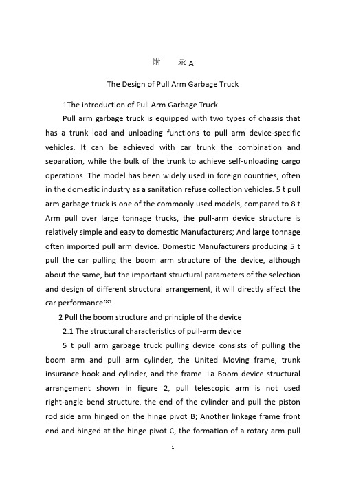
附录AThe Design of Pull Arm Garbage Truck1The introduction of Pull Arm Garbage TruckPull arm garbage truck is equipped with two types of chassis that has a trunk load and unloading functions to pull arm device-specific vehicles. It can be achieved with car trunk the combination and separation, while the bulk of the trunk to achieve self-unloading cargo operations. The model has been widely used in foreign countries, often in the domestic industry as a sanitation refuse collection vehicles. 5 t pull arm garbage truck is one of the commonly used models, compared to 8 t Arm pull over large tonnage trucks, the pull-arm device structure is relatively simple and easy to domestic Manufacturers; And large tonnage often imported pull arm device. Domestic Manufacturers producing 5 t pull the car pulling the boom arm structure of the device, although about the same, but the important structural parameters of the selection and design of different structural arrangement, it will directly affect the car performance]20[.2 Pull the boom structure and principle of the device2.1 The structural characteristics of pull-arm device5 t pull arm garbage truck pulling device consists of pulling the boom arm and pull arm cylinder, the United Moving frame, trunk insurance hook and cylinder, and the frame. La Boom device structural arrangement shown in figure 2, pull telescopic arm is not used right-angle bend structure. the end of the cylinder and pull the piston rod side arm hinged on the hinge pivot B; Another linkage frame front end and hinged at the hinge pivot C, the formation of a rotary arm pullheart. Cylinder head cylinder arm pull side hinged front frame on the hinge pivot A; linkage frame hinged rear axle frame rear hinge pivot D, the formation of linkage rotary frame heart. Insurance linkage trunk rack hook set the hook cylinder and insurance cylinder.2.2 The working principle of the device arm pullPulling garbage truck arm by pulling the device to complete the function of two different dynamic, for boxes and dumping. When the pull device for boom box action, the first cylinder insurance hook action open the trunk insurance hook, trunk lift insurance. Pull lift arm cylinder piston rod elongation from the pull arm, pull arm to pivot around the hinge C clockwise rotation, the hook arm to pull back move. If the frame is equipped with a trunk, the trunk was pushed home ground. When put on the frame, so that the first hook retractor trunk rings, and contraction of the piston rod, pull arm to hinge pivot counter-clockwise rotation axis C, will put on the flat trunk, the insurance cylinder hook action, pull carriages insurance hook fixed to the frame to the trunk.When the pull-arm device dumping action, and action for different box, trunk insurance hook dump in the whole process to ensure that tension in the arm and trunk are not isolated, that is pull arm、the linkage through the trunk rack and trunk link between the insurance as one of the hook, by the deputy rear frame hinge pivot clockwise rotation axis D, lifting carriages lifted until the refuse rubbish. Trunk reset, as long as the retraction of cylinder piston rod pull arm, the pulling arm body still hinge pivot point D is the shaft counterclockwise rotation, until the trunk reset.3 La Boom Selection and design of device structure parameters3.1 Device to pull the boom pivot hinge arrangement and geometryof the main structureDetermined by the following three areas:a. Arm by pulling a dump truck performance, it is 5 t pull the best selection of cars from the arm unloading chassis, the chassis can be selected according to the length of pull arm device to determine frame the total length. To ensure the car to pull arm for changing trunk and dumping action by the force of the chassis reasonable and complete the dumping arm pull action pivot hinge rotation axis D of the location should be arranged in behind the rear spring plate from the chassis rear bearing axis, the spacing is about 0 ~ 100 mm.b. According to the first hinge pivot D arm pull for me the beginning of the selected pivot hinge rotation axis C. In the design and production of the actual process of pulling the car arm in arm had appeared during the pull action although the initial state, pull arm lift carriages, failed to pull arm pivot around the hinge C rotation, but with the linkage frame with the rotation around the hinge pivot point D, which can not get trunk open the beginning of fall; when lifting a certain height, the action of gravity in the trunk, the hinge will pivot C a sudden fall, so pull arm, the linkage frame and carriages suddenly drop, resulting in relatively large; in hit, resulting in extremely unsafe for me a smooth action. To resolve this problem, determine the hinge point C of the axis position is especially important. First the one hand, the horizontal axis of pivot C can not above the level layout of pivot D. In addition, by the hinge can pivot C stress analysis know, the hinge pivot axis of C must be below the level of tension hinge pivot arm cylinder head horizontal axis, while the hook arm pull-start action must be arranged in the vertical axis of the hinge pivot between C and the hinge pivot left foot.c. Important geometrical parameters arm pull a pull arm foot radiusof gyration for pull the oil boom turning radius of the cylinder piston rod end of radius of gyration of the angle between the two radius. From the above points analysis we know that, The smaller of radius. The greater the force needed to pull the smaller cylinder arm. Meet the requirements under the premise of arms-for-me pull-foot turning radius, the smaller the better, La boom cylinder rod side radius of gyration R. The bigger the better as far as possible, so that can pull compact boom, operating small space]21[.3.2 The selection of pull arm cylinder and cylinder installation angle y. The range ofDetermined by the following two aspects:a. By mapping method or analytical method to determine the location of the above the hinge pivot and Pull arm geometry and other components, may initially determine the pull-stroke arm cylinder and installation distance.b. Pull arm cylinder mounting angle of La Boom is the important structural parameters of devices. By the former knowledge, pull the boom box or device for carrying out the process of dumping action, pull the oil boom cylinders have to be overcome trunk (full load) resistance torque generated by gravity, and the lifting crane action start unloading boxes when the moment of resistance is the greatest moment of resistance to overcome, and in Boom began pulling action of the hinge pivot device static friction and inertia moment of resistance Maximum torque. So pull arm cylinder mounting angle y. From the previous analysis we know, when angle larger, the pull arm cylinder smaller maximum thrust required, select the pull arm cylinder bore can be smaller.By pulling in the boom cylinder is installed between the frame andtrunk floor, oil cylinder installation layout space is limited, so the pull arm cylinder mounting angle range is also very limited. Design principles to children as much as possible to install a large angle, choose the right drawing arm oil pulling arm cylinder bore to meet performance requirements for the use of vehicles, without increasing the cost and fuel tank weight, and easy layout. Analysis and comparison of some domestic manufacturers to produce 5 t pull arm ,the actual design and production of cars and trucks pulling arm experience, 5 t pull arm around the installation space vehicles between 250 ~ 300 mm, the general tension arm cylinder mounting angle should be Taken between 3°~5°.附录B拉臂式垃圾车设计1拉臂车概述拉臂式垃圾车是在二类汽车底盘上装有使车箱具有装载和卸载功能的拉臂架装置的专用汽车。
机械设计外文文献翻译、中英文翻译

机械设计外文文献翻译、中英文翻译unavailable。
The first step in the design process is to define the problem and XXX are defined。
the designer can begin toXXX evaluated。
and the best one is XXX。
XXX.Mechanical DesignA XXX machines include engines。
turbines。
vehicles。
hoists。
printing presses。
washing machines。
and XXX and methods of design that apply to XXXXXX。
cams。
valves。
vessels。
and mixers.Design ProcessThe design process begins with a real need。
Existing apparatus may require XXX。
efficiency。
weight。
speed。
or cost。
while new apparatus may be XXX。
To start。
the designer must define the problem and XXX。
ideas and concepts are generated。
evaluated。
and refined until the best one is XXX。
XXX.XXX。
assembly。
XXX.During the preliminary design stage。
it is important to allow design XXX if some ideas may seem impractical。
they can be corrected early on in the design process。
机械设计外文翻译--机器人

Robotthe industrial robot is a tool that is used in the manufacturing environment to increase productivity.It can perform jobs that mights be hazardous to the human worker.One of the first industrial robots was used to replace the nuclear power plants.The industrial robot can also operate on the assembly line such as placing electronic components on a printed circuit board .Thus ,the human worker can be relieved of the routine operation of this tedious task .Robots can also be programmed to defuse bombs,to serve the handicapped ,and to perform functions in numerous applications in our society.A robot is a reprogrammable,multifunctional manipulator designed to more parts,materials tools or special devices through variable pregrammed locations for the performance of a variety of different tasks.Preprogrammed locations are paths that the robot must follow to accomplish work.At some of these locations ,the robot will stop and perform some operation,such as assembly of parts,spray painting,or welding.These ppreprogrammed locations are stored in the robot’s memory and are recalled later for continous operation.Furthermore,these preprogrammed locations,as well as other program data,can be changed later as the work requirements change .Thus ,with regard to this programming feature,an industrial robot is very much like a computer.The robotic system can also control the work cell of the operating robot.The work cell of the robot is the total enviroment in which the robot must perform its task.Included within this cell may be the robot manipulator,controller,a work table ,safety features,or a conveyor.In addition, signals from outside device can communicate with the robot.The manipulator,which does the physical work of the robotic system,consists of two sections:the mechanical section and the attached appendage.The manipulator also has a base to which the appendages are attached.The base of the manipulator is usually fixed to the floor of the work area.Sometimes,through,the base may be movable.In this case,the base is attached to either a rail or a track,allowing the manipulator to be moved from one location to another.the manipulator is mainly composed of the hand and the motion. The hand is uses for to grasp holds the work piece (or tool) the part, according to is grasped holds the thing shape, the size, the weight, the material and the work request has many kinds of structural styles, like the clamp, therequest hold and the adsorption and so on. The motion, causes the hand to complete each kind of rotation (swinging), the migration or the compound motion realizes the stipulation movement, changes is grasped holds the thing position and the posture. Motion's fluctuation, the expansion, revolving and so on independence movement way, is called manipulator's degree-of-freedom. In order to capture in the space the optional position and the position object, must have 6 degrees-of-freedom. The degree-of-freedom is the key parameter which the manipulator designs. The degree-of-freedom are more, manipulator's flexibility is bigger, the versatility is broader, its structure is also more complex. Generally the special-purpose manipulator has 2~3 degrees-of-freedom.The appendage is the arm of the robot.It can be either a straight,movable arm or a jointed arm and gives the manipulator its various axes of motion.The jointed arm is also known as an articulated arm.At the end of the arm,a wrist is connected.The wrist is made up of additional axes and a wrist flange.The wrist flange allows therobot user to connectdifferent tooling to the wrist for different jobs.The manipulator’saxes allow it to perform work within acertain area.This area is called the work cell of the robot,and its size corresponds to the size of the manipulator.As the robot’physical size increases,the size of the work cell must also increase.The movement of the manipulator is controlled by actuators, or drive system can use electric,hydraulic,or pneumatic power.The energy developed by the drive system is convered to mechanical power by various mechanical drive systems.The drive systems are coupled through mechanical linkages.These linkages,in turn,drive the different axes of the robot. The mechanical linkages may be composed of chains,geas,and ball screws.The controller is used to control the robot manipulator’movements as well as to control peripheral components within the work cell.The user can program themovements of the manipulator into the controller through the use of a hand-held teach pendant.This information is stored in the memory of the controller for later recall.The controller is also required to communicate with peripheral equipment within the work cell.For example,a controller has an input line.When the machine cycle is completed,the input line turns on ,telling the controller to position the manipulator so that it can pick up the finished part.Then ,a new part is picked up by the manipulator and placed into the machine.Next,the controller signals the machine to start operation.The controller can be made from mechanically operated drums that step through a sequence of events.This type of controller operates with simple robotic system.The controllers found on the majority of robotic systems are more complex devices and represent state-of-the-art electronics.That is,they are microprocessor-operated.This power allows the controller to be very flexible in its operation.The controller can send electric signals over communication lines.This two- way communication between the robot manipulator and the controller maintains a constant update of the location and the operation of the system.The controller also has the job of communicating with the different plant computer.The communication link establishes the robot as part of a computer-assisted manufacturing(CAM)system.The microprocessor-based systems operate in conjunction with solid-state memory devices.These memory devices may be magnetic bubbles,random-access memory,floppy disk,or magnetic tape.The power supply is the unit that supplies power to the controller and the manipulator.Two types of power are delived to the robotic system.One type of power is the Acpower for operation of the controller.The other type of power is used for driving the various axes of the manipulator.For example,if the robot manipulator is controlled by hydraulic or pneumatic drives,control signals are sent to these devices,causing motion of the robot.Industrial robots vary widely in size ,shape,number of axes,degrees of freedom,and design configuration .Each factor influences the dimensions of the robot’s working envelop or the volume of space within which it can move and perform its designated task.A broader classification of robots can been described as below.Fixed-and Variable-Sequence Robots .The fixed-sequence robot(also called a pick-and place robot)is programmed for a specific sequence of operqtions.Its movements are from point to point ,and the cycle is repeated continuously.The variable-sequence robot can be programmed for a specific sequence of operations but can be reprogrammed to perform another sequence of operation.Playback Robot.An operator leads or walks the playback robot and its end effector through the deired path .The robot memorizes and records the path and sequence of motions and can repeat them continually without any further action or guidance by the operator.Numerically Controlled Robot.The numerically cantrolled robot is programmed and operatedmuch like a numerically controlled machine .The robot is servocontrolled by digital data ,and its sequence of movements can be changed with relative ease.Intelligent Robot.[3]The intelligent robot is capable of performing some of the functions and tasks carried out by human beings .It is equipped with a variety of sensors with visual and tactile capabilities.机器人工业机器人是一种提高制造业生产力的工具,它可以承担那些对人类可能有危险的工作。
机械工程外文翻译
外文资料原文及译文学院:机电工程学院专业:机械设计制造及其自动化班级:学号:姓名:Mechanical engineering1.The porfile of mechanical engineeringEngingeering is a branch of mechanical engineerig,itstudies mechanical and power generation especially power and movement.2.The history of mechanical engineering18th century later periods,the steam engine invention hasprovided a main power fountainhead for the industrialrevolution,enormously impelled each kind of mechznicalbiting.Thus,an important branch of a new Engineering –separated from the civil engineering tools and machines on thebranch-developed together with Birmingham and the establishment of the Associantion of Mechanical Engineers in1847 had been officially recognized.The mechanicalengineering already mainly used in by trial and error methodmechanic application technological development intoprofessional engineer the scientific method of which in theresearch,the design and the realm of production used .From themost broad perspective,the demend continuously to enhance theefficiencey of mechanical engineers improve the quality of work,and asked him to accept the history of the high degreeof education and training.Machine operation to stress not onlyeconomic but also infrastructure costs to an absolute minimun.3.The field of mechanical engineeringThe commodity machinery development in the develop country,in the high level material life very great degree is decided each kind of which can realize in the mechanical engineering.Mechanical engineers unceasingly will invent the machine next life to produce the commodity,unceasingly will develop the accuracy and the complexity more and more high machine tools produces the machine.The main clues of the mechanical development is:In order to enhance the excellent in quality and reasonable in price produce to increase the precision as well as to reduce the production cost.This three requirements promoted the complex control system development.The most successful machine manufacture is its machine and the control system close fusion,whether such control system is essentially mechanical or electronic.The modernized car engin production transmission line(conveyer belt)is a series of complex productions craft mechanization very good example.The people are in the process of development in order to enable further automation of the production machinery ,the use of a computer to store and handle large volumes of data,the data is a multifunctional machine toolsnecessary for the production of spare parts.One of the objectives is to fully automated production workshop,three rotation,but only one officer per day to operate.The development of production for mechanical machinery must have adequate power supply.Steam engine first provided the heat to generate power using practical methods in the old human,wind and hydropower,an increase of engin .New mechanical engineering industry is one of the challenges faced by the initial increase thermal effciency and power,which is as big steam turbine and the development of joint steam boilers basically achieved.20th century,turbine generators to provide impetus has been sustained and rapid growth,while thermal efficiency is steady growth,and large power plants per kW capital consumption is also declining.Finally,mechanical engineers have nuclear energy.This requires the application of nuclear energy particularly high reliability and security, which requires solving many new rge power plants and the nuclear power plant control systems have become highly complex electroonics,fluid,electricity,water and mechanical parts networks All in all areas related to the mechanical engineers.Small internal combustion engine,both to the type (petrol and diesel machines)or rotary-type(gas turbines andMong Kerr machine),as well as their broad application in the field of transport should also due to mechanical enginerrs.Throughout the transport,both in the air and space,or in the terrestrial and marine,mechanial engineers created a variety of equipment and power devices to their increasing cooperation with electrical engineers,especially in the development of appropration control systems.Mechanical engineers in the development of military weapons technology and civil war ,needs a similar,though its purpose is to enhance rather than destroy their productivity.However.War needs a lot of resources to make the area of techonlogy,many have a far-reaching development in peacetime efficiency.Jet aircraft and nuclear reactors are well known examples.The Biological engineering,mechanical engineering biotechnology is a relatively new and different areas,it provides for the replacement of the machine or increase the body functions as well as for medical equipment.Artficial limbs have been developed and have such a strong movement and touch response function of the human body.In the development of artificial organ transplant is rapid,complex cardiac machines and similar equipment to enable increasingly complex surgery,and injuries and ill patients life functions can besustained.Some enviromental control mechanical engineers through the initial efforts to drainage or irrigation pumping to the land and to mine and ventilation to control the human environment.Modern refrigeration and air-conditioning plant commonaly used reverse heat engine,where the heat from the engine from cold places to more external heat.Many mechanical engineering products,as well as other leading technology development city have side effects on the environment,producing noise,water and air pollution caused,destroyed land and landscape.Improve productivity and diver too fast in the commodity,that the renewable natural forces keep pace.For mechanical engineers and others,environmental control is rapidly developing area,which includes a possible development and production of small quantities of pollutants machine sequnce,and the development of new equipment and teachnology has been to reduce and eliminate pollution.4.The role of mechanical engineeringThere are four generic mechanical engineers in common to the above all domains function.The 1st function is the understanding and the research mechanical science foundation.It includes the power and movement of therelationship dynamics For example,in the vibration and movement of the relationship;Automatic control;Study of the various forms of heart,energy,power relations between the thermodynamic;Fluidflows; Heat transfer; Lubricant;And material properties.The 2nd function will be conducts the research,the desing and the development,this function in turn attempts to carry on the essential change to satisfy current and the future needs.This not only calls for a clear understanding of mechanical science,and have to break down into basic elements of a complex system capacity.But also the need for synthetic and innovative inventions.The 3rd function is produces the product and the power,include plan,operation and maintenance.Its goal lies in the maintenance either enhances the enterprise or the organization longer-tern and survivabilaty prestige at the same time,produces the greatest value by the least investments and the consumption.The 4th function is mechanical engineer’s coordinated function,including the management,the consultation,as well as carries on the market marking in certain situation.In all these function,one kind unceasingly to use the science for a long time the method,but is not traditional orthe intuition method tendency,this is a mechanical engineering skill aspect which unceasingly grows.These new rationalization means typical names include:The operations research,the engineering economics,the logical law problem analysis(is called PABLA) However,creativity is not rationalization.As in other areas,in mechanical engineering, to take unexpected and important way to bring about a new capacity,still has a personal,marked characteristice.5.The design of mechanical engineeringThe design of mechanical is the design has the mechanical property the thing or the system,such as:the instrument and the measuring appliance in very many situations,the machine design must use the knowledge of discipline the and so on mathematics,materials science and mechanics.Mechanical engineering desgin includeing all mechanical desgin,but it was a study,because it also includes all the branches of mechsnical engineering,such as thermodynamics all hydrodynamics in the basic disciplines needed,in the mechanical engineering design of the initial stude or mechanical design.Design stages.The entire desgin process from start to finish,in the process,a demand that is designed for it and decided to do the start.After a lot of repetition,thefinal meet this demand by the end of the design procees and the plan.Design considerations.Sometimes in a system is to decide which parts needs intensity parts of geometric shapes and size an important factor in this context that we must consider that the intensity is an important factor in the design.When we use expression design considerations,we design parts that may affect the entire system design features.In the circumstances specified in the design,usually for a series of such functions must be taken into account.Howeever,to correct purposes,we should recognize that,in many cases the design of important design considerations are not calculated or test can determine the components or systems.Especially students,wheen in need to make important decisions in the design and conduct of any operation that can not be the case,they are often confused.These are not special,they occur every day,imagine,for example,a medical laboratory in the mechanical design,from marketing perspective,people have high expectations from the strength and relevance of impression.Thick,and heavy parts installed together:to produce a solid impression machines.And sometimes machinery and spare parts from the design style is the point and not the other point of view.Our purpose is to make those you do notbe misled to believe that every design decision will need reasonable mathematical methods.Manufacturing refers to the raw meterials into finished products in the enterprise.Create three distinct phases.They are:input,processing exprot.The first phase includes the production of all products in line with market needs essential.First there must be the demand for the product,the necessary materials,while also needs such as energy,time,human knowledge and technology resourcess . Finall,the need for funds to obtain all the other resources. Lose one stage after the second phase of the resources of the processes to be distributed.Processing of raw materials into finished products of these processes.To complete the design,based on the design,and then develop plans.Plan implemented through various production processes.Management of resources and processes to ensure efficiency and productivity.For example,we must carefully manage resources to ensure proper use of funds.Finally,people are talking about the product market was cast.Stage is the final stage of exporting finished or stage.Once finished just purchased,it must be delivered to the users.According to product performance,installation and may have to conduct furtherdebugging in addition,some products,especially those very complex products User training is necessary.6.The processes of materials and maunfacturingHere said engineering materials into two main categories:metals and non-ferrous,high-performance alloys and power metals.Non-metallic futher divided into plastice,synthetic rubber,composite materials and ceramics.It said the production proccess is divided into several major process,includingshape,forging,casting/ founding,heat treatment,fixed/connections ,measurement/ quality control and materal cutting.These processes can be further divide into each other’s craft.Various stages of the development of the manufacturing industry Over the years,the manufacturing process has four distinct stages of development, despite the overlap.These stages are:The first phase is artisanal,the second Phase is mechanization.The third phase is automation the forth Phase is integrated.When mankind initial processing of raw materials into finished products will be,they use manual processes.Each with their hands and what are the tools manuslly produced.This is totally integrated production take shape.A person needs indentification,collection materials,the design of a productto meet that demand,the production of such products and use it.From beginning to end,everything is focused on doing the work of the human ter in the industrial revolution introduced mechanized production process,people began to use machines to complete the work accomplished previously manual. This led to the specialization.Specialization in turn reduce the manufacture of integrated factors.In this stage of development,manufacturing workers can see their production as a whole represent a specific piece of the part of the production process.One can not say that their work is how to cope with the entire production process,or how they were loaded onto a production of parts finished.Development of manufacting processes is the next phase of the selection process automation.This is a computer-controlled machinery and processes.At this stage,automation island began to emerge in the workshop lane.Each island represents a clear production process or a group of processes.Although these automated isolated island within the island did raise the productivity of indivdual processes,but the overall productivity are often not change.This is because the island is not caught in other automated production process middle,but not synchronous with them .The ultimate result is the efficient working fast parkedthrough automated processes,but is part of the stagnation in wages down,causing bottlenecks.To better understand this problem,you can imagine the traffic in the peak driving a red light from the red Service Department to the next scene. Occasionally you will find a lot less cars,more than being slow-moving vehicles,but the results can be found by the next red light Brance.In short you real effect was to accelerate the speed of a red Department obstruction offset.If you and other drivers can change your speed and red light simultaneously.Will advance faster.Then,all cars will be consistent,sommth operation,the final everyone forward faster.In the workshop where the demand for stable synchronization of streamlined production,and promoted integration of manufacturing development.This is a still evolving technology.Fully integrated in the circumstances,is a computer-controllrd machinery and processing.integrated is completed through computer.For example in the preceding paragraph simulation problems,the computer will allow all road vehicles compatible with the change in red.So that everyone can steady traffic.Scientific analysis of movement,timing and mechanics of the disciplines is that it is composed of two pater:staticsand dynamics.Statics analyzed static system that is in the system,the time is not taken into account,research and analysis over time and dynamics of the system change.Dynameics from the two componets.Euler in 1775 will be the first time two different branches: Rigid body movement studies can conveniently divided into two parts:geometric and mechanics.The first part is without taking into account the reasons for the downward movement study rigid body from a designated location to another point of the movement,and must use the formula to reflect the actual,the formula would determine the rigid body every point position. Therefore,this study only on the geometry and,more specifically,on the entities from excision.Obviously,the first part of the school and was part of a mechanical separation from the principles of dynamics to study movement,which is more than the two parts together into a lot easier.Dynamics of the two parts are subsequently divided into two separate disciplines,kinematic and dynamics,a study of movement and the movement strength.Therefore,the primary issue is the design of mechanical systems understand its kinematic.Kinematic studies movement,rather than a study of its impact.In a more precise kinematic studies position,displacement,rotation,speed,velocity and acceleration of disciplines,for esample,or planets orbiting research campaing is a paradigm.In the above quotation content should be pay attention that the content of the Euler dynamics into kinematic and rigid body dynamics is based on the assumption that they are based on research.In this very important basis to allow for the treatment of two separate disciplines.For soft body,soft body shape and even their own soft objects in the campaign depends on the role of power in their possession.In such cases,should also study the power and movement,and therefore to a large extent the analysis of the increased complexity.Fortunately, despite the real machine parts may be involved are more or less the design of machines,usually with heavy material designed to bend down to the lowest parts.Therefore,when the kinematic analysis of the performance of machines,it is often assumed that bend is negligible,spare parts are hard,but when the load is known,in the end analysis engine,re-engineering parts to confirm this assnmption.机械工程1.机械工程简介机械工程是工程学的一个分支,它研究机械和动力的产,尤其是力和动力。
机械专业毕业设计外文翻译1

本科毕业设计(本科毕业论文)外文文献及译文文献、资料题目:High-rise Tower Crane designed文献、资料来源:期刊(著作、网络等)文献、资料发表(出版)日期:2000.3.25院(部):机电工程学院专业:机电工程及自动化High-rise Tower Crane designed under Turbulent Winds At present, construction of tower cranes is an important transport operations lifting equipment, tower crane accident the people's livelihood, major hazards, and is currently a large number of tower crane drivers although there are job permits, due to the lack of means to monitor and review the actual work of a serious violation . Strengthen the inspection and assessment is very important. Tower crane tipping the cause of the accident can be divided into two aspects: on the one hand, as a result of the management of tower cranes in place, illegal operation, illegal overloading inclined cable-stayed suspended widespread phenomenon; Second, because of the tower crane safety can not be found in time For example,Took place in the tower crane foundation tilt, micro-cracks appear critical weld, bolts loosening the case of failure to make timely inspection, maintenance, resulting in the continued use of tower cranes in the process of further deterioration of the potential defect, eventually leading to the tower crane tipping. The current limit of tower crane and the black box and can not be found to connect slewing tower and high-strength bolts loosening tightened after the phenomenon is not timely, not tower verticality of the axis line of the lateral-line real-time measurement, do not have to fight the anti-rotation vehicles, lifting bodies plummeted Meng Fang, hook hoists inclined cable is a timely reminder and record of the function, the wind can not be contained in the state of suspended operation to prevent tipping on the necessary tips on site there is a general phenomenon of the overloaded overturning of the whole security risks can not be accurately given a reminder and so on, all of which the lease on the tower crane, use, management problems,Through the use of tower crane anti-tipping monitor to be resolved. Tower crane anti-tipping Monitor is a new high-tech security monitoring equipment, and its principle for the use of machine vision technology and image processing technology to achieve the measurement of the tilt tower, tower crane on the work of state or non-working state of a variety of reasons angle of the tower caused by the critical state to achieve the alarm, prompt drivers to stop illegal operation, a computer chip at the same time on the work of the state of tower crane be recorded. Tower crane at least 1 day overload condition occurs, a maximum number of days to reach 23 overloading, the driver to operate the process of playing the anti-car, stop hanging urgency, such as cable-stayed suspended oblique phenomenon often, after verification and education, to avoid the possible occurrence of fatal accidents. Wind conditions in the anti-tipping is particularly important, tower cranes sometimes connected with the pin hole and pin do not meet design requirements, to connect high-strength bolts are not loose in time after the tightening of the phenomenon, through timely maintenance in time after the tightening of the phenomenon, through timely maintenance and remedial measures to ensure that the safe and reliable construction progress. Reduced lateral line tower vertical axis measuring the number of degrees,Observation tower angle driver to go to work and organize the data once a month to ensure that the lateral body axis vertical line to meet the requirements, do not have to every time and professionals must be completed by Theodolite tower vertical axismeasuring the lateral line, simplified the management link. Data logging function to ensure that responsibility for the accident that the scientific nature to improve the management of data records for the tower crane tower crane life prediction and diagnosis of steel structures intact state data provides a basis for scientific management and proactive prevention of possible accidents, the most important thing is, if the joint use of the black box can be easily and realistically meet the current provisions of the country's related industries. Tower crane safety management at the scene of great importance occurred in the construction process should be to repair damaged steel, usually have to do a good job in the steel tower crane maintenance work and found that damage to steel structures, we must rule out potential causes of accidents, to ensure safety in production carried out smoothly. Tower crane in the building construction has become essential to the construction of mechanical equipment, tower crane at the construction site in the management of safety in production is extremely important. A long time, people in the maintenance of tower crane, only to drive attention to the conservation and electrical equipment at the expense of inspection and repair of steel structures, to bring all kinds of construction accidents.Conclusion: The tower crane anti-tipping trial monitor to eliminate potential causes of accidents to provide accurate and timely information, the tower crane to ensure the smooth development of the leasing business, the decision is correct, and should further strengthen and standardize the use of the environment (including new staff training and development of data processing system, etc.).The first construction cranes were probably invented by the Ancient Greeks and were powered by men or beasts of burden, such as donkeys. These cranes were used for the construction of tall buildings. Larger cranes were later developed, employing the use of human treadwheels, permitting the lifting of heavier weights. In the High Middle Ages, harbour cranes were introduced to load and unload ships and assist with their construction – some were built into stone towers for extra strength and stability. The earliest cranes were constructed from wood, but cast iron and steel took over with the coming of the Industrial Revolution.For many centuries, power was supplied by the physical exertion of men or animals, although hoists in watermills and windmills could be driven by the harnessed natural power. The first 'mechanical' power was provided by steam engines, the earliest steam crane being introduced in the 18th or 19th century, with many remaining in use well into the late 20th century. Modern cranes usually use internal combustion engines or electric motors and hydraulic systems to provide a much greater lifting capability than was previously possible, although manual cranes are still utilised where the provision of power would be uneconomic.Cranes exist in an enormous variety of forms – each tailored to a specific use. Sizes range from the smallest jib cranes, used inside workshops, to the tallest tower cranes,used for constructing high buildings, and the largest floating cranes, used to build oil rigs and salvage sunken ships.This article also covers lifting machines that do not strictly fit the above definition of a crane, but are generally known as cranes, such as stacker cranes and loader cranes.The crane for lifting heavy loads was invented by the Ancient Greeks in the late 6th century BC. The archaeological record shows that no later than c.515 BC distinctive cuttings for both lifting tongs and lewis irons begin to appear on stone blocks of Greek temples. Since these holes point at the use of a lifting device, and since they are to be found either above the center of gravity of the block, or in pairs equidistant from a point over the center of gravity, they are regarded by archaeologists as the positive evidence required for the existence of the crane.The introduction of the winch and pulley hoist soon lead to a widespread replacement of ramps as the main means of vertical motion. For the next two hundred years, Greek building sites witnessed a sharp drop in the weights handled, as the new lifting technique made the use of several smaller stones more practical than of fewer larger ones. In contrast to the archaic period with its tendency to ever-increasing block sizes, Greek temples of the classical age like the Parthenon invariably featured stone blocks weighing less than 15-20 tons. Also, the practice of erecting large monolithic columns was practically abandoned in favour of using several column drums.Although the exact circumstances of the shift from the ramp to the crane technology remain unclear, it has been argued that the volatile social and political conditions of Greece were more suitable to the employment of small, professional construction teams than of large bodies of unskilled labour, making the crane more preferable to the Greek polis than the more labour-intensive ramp which had been the norm in the autocratic societies of Egypt or Assyria.The first unequivocal literary evidence for the existence of the compound pulley system appears in the Mechanical Problems (Mech. 18, 853a32-853b13) attributed to Aristotle (384-322 BC), but perhaps composed at a slightly later date. Around the same time, block sizes at Greek temples began to match their archaic predecessors again, indicating that the more sophisticated compound pulley must have found its way to Greek construction sites by then.During the High Middle Ages, the treadwheel crane was reintroduced on a large scale after the technology had fallen into disuse in western Europe with the demise of the Western Roman Empire. The earliest reference to a treadwheel (magna rota) reappears in archival literature in France about 1225, followed by an illuminated depiction in a manuscript of probably also French origin dating to 1240. In navigation, the earliest uses of harbor cranes are documented for Utrecht in 1244, Antwerp in 1263, Brugge in 1288 and Hamburg in 1291, while in England the treadwheel is not recorded before 1331.Generally, vertical transport could be done more safely and inexpensively by cranes than by customary methods. Typical areas of application were harbors, mines, and, in particular, building sites where the treadwheel crane played a pivotal role in the construction of the lofty Gothic cathedrals. Nevertheless, both archival and pictorial sources of the time suggest that newly introduced machines like treadwheels or wheelbarrows did not completely replace more labor-intensive methods like ladders, hods and handbarrows. Rather, old and new machinery continued to coexist on medieval construction sites and harbors.Apart from treadwheels, medieval depictions also show cranes to be powered manually by windlasses with radiating spokes, cranks and by the 15th century also by windlasses shaped like a ship's wheel. To smooth out irregularities of impulse and get over 'dead-spots' in the lifting process flywheels are known to be in use as early as 1123.The exact process by which the treadwheel crane was reintroduced is not recorded, although its return to construction sites has undoubtedly to be viewed in close connection with the simultaneous rise of Gothic architecture. The reappearance of the treadwheel crane may have resulted from a technological development of the windlass from which the treadwheel structurally and mechanically evolved. Alternatively, the medieval treadwheel may represent a deliberate reinvention of its Roman counterpart drawn from Vitruvius' De architectura which was available in many monastic libraries. Its reintroduction may have been inspired, as well, by the observation of the labor-saving qualities of the waterwheel with which early treadwheels shared many structural similarities.In contrast to modern cranes, medieval cranes and hoists - much like their counterparts in Greece and Rome - were primarily capable of a vertical lift, and not used to move loads for a considerable distance horizontally as well. Accordingly, lifting work was organized at the workplace in a different way than today. In building construction, for example, it is assumed that the crane lifted the stone blocks either from the bottom directly into place, or from a place opposite the centre of the wall from where it could deliver the blocks for two teams working at each end of the wall. Additionally, the crane master who usually gave orders at the treadwheel workers from outside the crane was able to manipulate the movement laterally by a small rope attached to the load. Slewing cranes which allowed a rotation of the load and were thus particularly suited for dockside work appeared as early as 1340. While ashlar blocks were directly lifted by sling, lewis or devil's clamp (German Teufelskralle), other objects were placed before in containers like pallets, baskets, wooden boxes or barrels.It is noteworthy that medieval cranes rarely featured ratchets or brakes to forestall the load from running backward.[25] This curious absence is explained by the high friction force exercised by medieval treadwheels which normally prevented the wheel from accelerating beyond control.目前,塔式起重机是建筑工程进行起重运输作业的重要设备,塔机事故关系国计民生、危害重大,而目前众多的塔机司机虽然有上岗证,由于缺少监督和复核手段,实际工作中违规严重。
机械专业毕业设计外文翻译--机械传动系统介绍

Transmission System introducedThe important position of the wheel gear and shaft can’t falter in traditional machine and modern machines. The wheel gear and shafts mainly install the direction that delivers the dint at the principal axis box. The passing to process to make them can is divided into many model numbers, used for many situations respectively. so we must be the multilayers to the understanding of the wheel gear and shaft in many ways.In the force analysis of spur gears, the forces are assumed to act in a single plane. We shall study gears in which the forces have three dimensions. The reason for this, in the case of helical gears, is that the teeth are not parallel to the axis of rotation. And in the case of bevel gears, the rotational axes are not parallel to each other. There are also other reasons, as we shall learn.Helical gears are used to transmit motion between parallel shafts. The helix angle is the same on each gear, but one gear must have a right-hand helix and the other a left-hand helix. The shape of the tooth is an involute helicoid. If a piece of paper cut in the shape of a parallelogram is wrapped around a cylinder, the angular edge of the paper becomes a helix. If we unwind this paper, each point on the angular edge generates an involute curve. The surface obtained when every point on the edge generates an involute is called an involute helicoids.The initial contact of spur-gear teeth is a line extending all the way across the face of the tooth. The initial contact of helical gear teeth is a point, which changes into a line as line as the teeth come into more engagement. In spur gears the line of contact is parallel to the axis of the rotation; in helical gears, the line is diagonal across the face of the tooth. It is this gradual of the teeth and the smooth transfer of load from one tooth to another, which give helical gears the ability to transmit heavy loads at high speeds. Helical gears subject the shaft bearings to both radial and thrust loads. When the thrust loads become high or are objectionable for other reasons, it may be desirable to use double helical gears. A double helical gear (herringbone) is equivalent to two helical gears of opposite hand, mounted side by side on the same shaft. They develop opposite thrust reactions and thus cancel out the thrust load. When two or more single helical gears are mounted on the same shaft, the hand of the gears should be selected so as to produce the minimum thrust load.Crossed-helical, or spiral, gears are those in which the shaft centerlines are neither parallel nor interesting. The teeth of crossed-helical fears have point contact with each other which changes to line contact as the gears wear in. for this reason they will carry out very small loads and are mainly for instrumental applications, and are definitely not recommended for use in the transmission of power. There is on difference between a crossed helical gear and a helical gear until they are mounted in mesh with each other. They are manufactured in the same way. A pair of meshed crossed helical gears usually have the same hand; that is, a right-hand driver goes with a right-hand driven. In the design of crossed-helical gears, the minimum sliding velocity is obtained when the helix angle are equal. However, when the helix angle are not equal, the gear with the larger helix angle should be used as the driver if both gears have the same hand.Worm gears are similar to crossed helical gears. The pinion or worm has a small number of teeth, usually one to four, and since they completely wrap around the pitch cylinder they are called threads. Its mating gear is called a worm gear, which is not a true helical gear. A worm and worm gear are used to provide a high angular-velocity reduction between nonintersecting shafts which are usually at right angle. The worm gear is not a helical gear because its face is made concave to fit the curvature of the worm in order to provide line contact instead of point contact. However, a disadvantage of worm gearing is the high sliding velocities across the teeth, the same as with crossed helical gears.Worm gearing are either single or double enveloping. A single-enveloping gearing is one in which the gear wraps around or partially encloses the worm. A gearing in which each element partially encloses the other is, of course, a double-enveloping worm gearing. The important difference between the two is that area contact exists between the teeth of double-enveloping gears while only line contact between those of single-enveloping gears. The worm and worm gear of a set have the same hand of helix as for crossed helical gears, but the helix angles are usually quite different. The helix angle on the worm is generally quite large, and that on the gear very small. Because of this, it is usual to specify the lead angle on the worm, which is the complement of the worm helix angle, and the helix angle on the gear; the two angles ate equal for a 90-deg. Shaft angle.When gears are to be used to transmit motion between intersecting shaft, some ofbevel gear is required. Although bevel gear are usually made for a shaft angle of 90 deg. They may be produced for almost any shaft angle. The teeth may be cast, milled, or generated. Only the generated teeth may be classed as accurate. In a typical bevel gear mounting, one of the gear is often mounted outboard of the bearing this means that shaft deflection can be more pronounced and have a greater effect in the contact of teeth. Another difficulty, which occurs in predicting the stress in bevel-gear teeth, is the fact the teeth are tapered.Straight bevel gears are easy to design and simple to manufacture and give very good results in service if they are mounted accurately and positively. As in the case of squrgears, however, they become noisy at higher values of the pitch-line velocity. In these cases it is often good design practice to go to the spiral bevel gear, which is the bevel counterpart of the helical gear. As in the case of helical gears, spiral bevel gears give a much smoother tooth action than straight bevel gears, and hence are useful where high speed are encountered.It is frequently desirable, as in the case of automotive differential applications, to have gearing similar to bevel gears but with the shaft offset Such gears are called hypoid gears because their pitch surfaces are hyperboloids of revolution The tooth action between such gears is a combination of rolling and has much in common with that of worm gears.A shaft is a rotating or stationary member usually of circular cross section, having mounted upon it such elementsas gears pulleys flywheels, cranks sprockets and other power-transmission elements Shaft may be subjected to bending tension compression or torsional loads acting singly or in combination with one another .When they are combined one may expect to find both static and fatigue strength to be important design considerations since a single shaft may be subjected to static stresses completely reversed, and repeated stresses, all acting at the same timeThe word “shaft” covers numerous wariations, such as axles and spindles. Anaxle is a shaft, wither stationary or rotating nor subjected to torsion load. Ashirt rotating shaft is often called a spindle.When either the lateral or the tosional deflection of shaft must be held to close limits, the shaft must be sized on the basis of deflection before analyzing the stresses The reasonfor this is that if the shift is made stiff enough so that the deflection is not too large, it is probable that the resulting stresses will be safe. But by no means should the designer assume that they are within acceptable limits. Whenever possible the power-transmission elements such as gears or pullets, should be located close to the supporting bearings. This reduces the bending moment, and hence the deflection and bending stress.Although the von Mises-Hencky-Goodman method is difficult to use in design of shaft, it probably come closest to predicting actual failure. Thus it is a good way of checking a shaft that has already been designed or of discovering why a particular shaft that has already been designed or of discovering why a particular shaft has failed in service. Furthermore, there are a considerable number of shaft-design problems in which the dimension are pretty well limited by other considerations, such as rigidity, and it is only necessary for the designer to discover something about the fillet sizes, heat-treatment, and surface finish and whether or not shot peening is necessary in order to achieve the required life and reliability.Because of the similarity of their functions, clutches and brakes are treated together. In a simplified dynamic representation of a friction clutch, or brake, two inertias I1and I2 traveling at the respective angular velocities W1 and W2, one of which may be zero in the case of brake, are to be brought to the same speed by engaging the clutch or brake. Slippage occurs because the two elements are running at different speeds and energy is dissipated during actuation, resulting in a temperature rise. In analyzing the performance of these devices we shall be interested in the actuating force, the torque transmitted, the energy loss and the temperature rise. The torque transmitted is related to the actuating force, the coefficient of friction, and the geometry of the clutch or brake. This is problem in static, which will have to be studied separately for each geometric configuration. However, temperature rise is related to energy loss and can be studied without regard to the type of brake or clutch because the geometry of interest is the hear-dissipating surfaces. The various types of clutches and brakes may be classified as fallows:Rim type with internally expanding shoesRim type with internally contracting shoesBand typeDisk or axial typeCone typeMiscellaneous typeThe analysis of all type of friction clutches and brakes use the same general procedure. The following step are necessary:1. Assume or determine the distribution of pressure on the frictionalsurfaces.2. Find a relation between the maximum pressure and the pressure at any point3. apply the condition of statical equilibrium to find (a) the actuating force, (b) the torque, and (c) the support reactions.Miscellaneous clutches include several type, such as the positive-contact clutches, overload-release clutches, overrunning clutches, magnetic fluid clutches, and others.A positive-contact clutch consists of a shift lever and two jaws. The greatest differences between the various types of positive clutches are concerned with the design of the jaws. To provide a longer period of time for shift action during engagement, the jaws may be ratchet-shaped, or gear-tooth-shaped. Sometimes a great many teeth or jaws re used, and they may be cut either circumferentially, so that they engage by cylindrical mating, or on the faces of the mating elements.Although positive clutches are not used to the extent the frictional-contact type, they do have important applications where synchronous operation is required.Devices such as linear driver or motor-operated screw drivers must run to definite limit and then come to a stop. An over load-release rype of clutch is required for these applications. These clutches are usually spring-loaded so as to release at a predetermined toque. The clicking sound which is heard when the overload point is reached is considered to be a desirable signal.An overrunning clutch or coupling permits the driven member of a machine to “freewheel” or “overrun” because the driver is stopped or because another source of power increase the speed of the driven. This type of clutch usually uses rollers or balls mounted between an outer sleeve and an inner member having flats machined around the periphery. Driving action is obtained by wedding the rollers between the sleeve and the flats. The clutch is therefore equivalent to a pawl and ratchet with an infinite number of teeth.Magnetic fluid clutch or brake is a relatively new development which has two parallel magnetic plates. Between these plates is a lubricated magnetic powder mixture. An electromagnetic coil is inserted somewhere in the magnetic circuit. Bu varying the excitation to this coil, the shearing strength of the magnetic fluid mixture may be accurately controlled. Thus any condition from a full slip to a frozen lockup may be obtained.机械传动系统介绍在传统机械和现代机械中齿轮和轴的重要地位是不可动摇的。
机械类毕业设计外文翻译---轴承的摩擦与润滑

外文文献原文:Friction , Lubrication of BearingIn many of the problem thus far , the student has been asked to disregard or neglect friction . Actually , friction is present to some degree whenever two parts are in contact and move on each other. The term friction refers to the resistance of two or more parts to movement.Friction is harmful or valuable depending upon where it occurs. friction is necessary for fastening devices such as screws and rivets which depend upon friction to hold the fastener and the parts together. Belt drivers, brakes, and tires are additional applications where friction is necessary.The friction of moving parts in a machine is harmful because it reduces the mechanical advantage of the device. The heat produced by friction is lost energy because no work takes place. Also , greater power is required to overcome the increased friction. Heat is destructive in that it causes expansion. Expansion may cause a bearing or sliding surface to fit tighter. If a great enough pressure builds up because made from low temperature materials may melt.There are three types of friction which must be overcome in moving parts: (1)starting, (2)sliding, and(3)rolling. Starting friction is the friction between two solids that tend to resist movement. When two parts are at a state of rest, the surface irregularities of both parts tend to interlock and form a wedging action. To produce motion in these parts, the wedge-shaped peaks and valleys of the stationary surfaces must be made to slide out and over each other. The rougher the two surfaces, the greater is starting friction resulting from their movement .Since there is usually no fixed pattern between the peaks and valleys of two mating parts, the irregularities do not interlock once the parts are in motion but slide over each other. The friction of the two surfaces is known as sliding friction. As shown in figure ,starting friction is always greater than sliding friction .Rolling friction occurs when roller devces are subjected to tremendous stress which cause the parts to change shape or deform. Under these conditions, the material in front of a roller tends to pile up and forces the object to roll slightly uphill. This changing of shape , known as deformation, causes a movement of molecules.As a result ,heat is produced from the added energy required to keep the parts turning and overcome friction.The friction caused by the wedging action of surface irregularities can be overcome partly by the precision machining of the surfaces. However, even these smooth surfaces may require the use of a substance between them to reduce the friction still more. This substance is usually a lubricant which provides a fine, thin oil film. The film keeps the surfaces apart and prevents the cohesive forces of the surfaces from coming in close contact and producing heat .Another way to reduce friction is to use different materials for the bearing surfaces and rotating parts. This explains why bronze bearings, soft alloys, and copper and tin iolite bearings are used with both soft and hardened steel shaft. The iolite bearing is porous. Thus, when the bearing is dipped in oil, capillary action carries the oil through the spaces of the bearing. This type of bearing carries its own lubricant to the points where the pressures are the greatest.Moving parts are lubricated to reduce friction, wear, and heat. The most commonly used lubricants are oils, greases, and graphite compounds. Each lubricant serves a different purpose. The conditions under which two moving surfaces are to work determine the type of lubricant to be used and the system selected for distributing the lubricant.On slow moving parts with a minimum of pressure, an oil groove is usually sufficient to distribute the required quantity of lubricant to the surfaces moving on each other .A second common method of lubrication is the splash system in which parts moving in a reservoir of lubricant pick up sufficient oil which is then distributed to all moving parts during each cycle. This system is used in the crankcase of lawn-mower engines to lubricate the crankshaft, connecting rod ,and parts of the piston.A lubrication system commonly used in industrial plants is the pressure system. In this system, a pump on a machine carries the lubricant to all of the bearing surfaces at a constant rate and quantity.There are numerous other systems of lubrication and a considerable number of lubricants available for any given set of operating conditions. Modern industrypays greater attention to the use of the proper lubricants than at previous time because of the increased speeds, pressures, and operating demands placed on equipment and devices.Although one of the main purposes of lubrication is reduce friction, any substance-liquid , solid , or gaseous-capable of controlling friction and wear between sliding surfaces can be classed as a lubricant.V arieties of lubricationUnlubricated sliding. Metals that have been carefully treated to remove all foreign materials seize and weld to one another when slid together. In the absence of such a high degree of cleanliness, adsorbed gases, water vapor ,oxides, and contaminants reduce frictio9n and the tendency to seize but usually result in severe wear; this is called “unlubricated ”or dry sliding.Fluid-film lubrication. Interposing a fluid film that completely separates the sliding surfaces results in fluid-film lubrication. The fluid may be introduced intentionally as the oil in the main bearing of an automobile, or unintentionally, as in the case of water between a smooth tuber tire and a wet pavement. Although the fluid is usually a liquid such as oil, water, and a wide range of other materials, it may also be a gas. The gas most commonly employed is air.Boundary lubrication. A condition that lies between unlubricated sliding and fluid-film lubrication is referred to as boundary lubrication, also defined as that condition of lubrication in which the friction between surfaces is determined by the properties of the surfaces and properties of the lubricant other than viscosity. Boundary lubrication encompasses a significant portion of lubrication phenomena and commonly occurs during the starting and stopping off machines.Solid lubrication. Solid such as graphite and molybdenum disulfide are widely used when normal lubricants do not possess sufficient resistance to load or temperature extremes. But lubricants need not take only such familiar forms as fats, powders, and gases; even some metals commonly serve as sliding surfaces in some sophisticated machines.Function of lubricantsAlthough a lubricant primarily controls friction and ordinarily does perform numerous other functions, which vary with the application and usually are interrelated .Friction control. The amount and character of the lubricant made available to sliding surfaces have a profound effect upon the friction that is encountered. For example, disregarding such related factors as heat and wear but considering friction alone between the same surfaces with on lubricant. Under fluid-film conditions, friction is encountered. In a great range of viscosities and thus can satisfy a broad spectrum of functional requirements. Under boundary lubrication conditions , the effect of viscosity on friction becomes less significant than the chemical nature of the lubricant.Wear control. wear occurs on lubricated surfaces by abrasion, corrosion ,and solid-to-solid contact wear by providing a film that increases the distance between the sliding surfaces ,thereby lessening the damage by abrasive contaminants and surface asperities.T emperature control. Lubricants assist in controlling corrosion of the surfaces themselves is twofold. When machinery is idle, the lubricant acts as a preservative. When machinery is in use, the lubricant controls corrosion by coating lubricated parts with a protective film that may contain additives to neutralize corrosive materials. The ability of a lubricant to control corrosion is directly relatly to the thickness of the lubricant film remaining on the metal surfaces and the chermical composition of the lubricant.Other functionsLubrication are frequently used for purposes other than the reduction of friction. Some of these applications are described below.Power transmission. Lubricants are widely employed as hydraulic fluids in fluid transmission devices.Insulation. In specialized applications such as transformers and switchgear , lubricants with high dielectric constants acts as electrical insulators. For maximum insulating properties, a lubricant must be kept free of contaminants and water.Shock dampening. Lubricants act as shock-dampening fluids in energy transferring devices such as shock absorbers and around machine parts such as gears that are subjected to high intermittent loads.Sealing. Lubricating grease frequently performs the special function of forming a seal to retain lubricants or to exclude contaminants.The object of lubrication is to reduce friction ,wear , and heating of machine pars which move relative to each other. A lubricant is any substance which, when inserted between the moving surfaces, accomplishes these purposes. Most lubricants are liquids(such as mineral oil, silicone fluids, and water),but they may be solid for use in dry bearings, greases for use in rolling element bearing, or gases(such as air) for use in gas bearings. The physical and chemical interaction between the lubricant and lubricating surfaces must be understood in order to provide the machine elements with satisfactory life.The understanding of boundary lubrication is normally attributed to hardy and doubleday , who found the extrememly thin films adhering to surfaces were often sufficient to assist relative sliding. They concluded that under such circumstances the chemical composition of fluid is important, and they introduced the term “boundary lubrication”. Boundary lubric ation is at the opposite end of the spectrum from hydrodynamic lubrication.Five distinct of forms of lubrication that may be defined :(a) hydrodynamic;(b)hydrostatic;(c)elastohydrodynamic (d)boundary; (e)solid film.Hydrodynamic lubrication means that the load-carrying surfaces of the bearing are separated by a relatively thick film of lubricant, so as to prevent metal contact, and that the stability thus obtained can be explained by the laws of the lubricant under pressure ,though it may be; but it does require the existence of an adequate supply at all times. The film pressure is created by the moving surfaces itself pulling the lubricant under pressure, though it maybe. The film pressure is created by the moving surface to creat the pressure necessary to separate the surfaces against the load on the bearing . hydrodynamic lubrication is also called full film ,or fluid lubrication .Hydrostatic lubrication is obtained by introducing the lubricant ,which is sometime air or water ,into the load-bearing area at a pressure high enough to separate the surface with a relatively thick film of lubricant. So ,unlike hydrodynanmic lubrication, motion of one surface relative to another is not required .Elasohydrodynamic lubrication is the phenomenon that occurs when a lubricant is introduced between surfaces which are in rolling contact, such as mating gears or rolling bearings. The mathematical explanation requires the hertzian theory of contact stress and fluid mechanics.When bearing must be operated at exetreme temperatures, a solid film lubricant such as graphite or molybdenum disulfide must be use used because the ordinary mineral oils are not satisfactory. Must research is currently being carried out in an effort, too, to find composite bearing materials with low wear rates as well as small frictional coefficients.In a journal bearing, a shaft rotates or oscillates within the bearing , and the relative motion is sliding . in an antifriction bearing, the main relative motion is rolling . a follower may either roll or slide on the cam. Gear teeth mate with each other by a combination of rolling and sliding . pistions slide within their cylinders. All these applications require lubrication to reduce friction ,wear, and heating.The field of application for journal bearing s is immense. The crankshaft and connecting rod bearings of an automotive engine must poerate for thousands of miles at high temperatures and under varying load conditions . the journal bearings used in the steam turbines of power generating station is said to have reliabilities approaching 100 percent. At the other extreme there are thousands of applications in which the loads are light and the service relatively unimportant. a simple ,easily installed bearing is required ,suing little or no lubrication. In such cases an antifriction bearing might be a poor answer because because of the cost, the close ,the radial space required ,or the increased inertial effects. Recent metallurgy developments in bearing materials , combined with increased knowledge of the lubrication process, now make it possible to design journal bearings with satisfactory lives and very good reliabilities.中文译文:轴承的摩擦与润滑现在看来,有很多这种情况,许多学生在被问到关于摩擦的问题时,往往都没引起足够的重视,甚至是忽视它。
- 1、下载文档前请自行甄别文档内容的完整性,平台不提供额外的编辑、内容补充、找答案等附加服务。
- 2、"仅部分预览"的文档,不可在线预览部分如存在完整性等问题,可反馈申请退款(可完整预览的文档不适用该条件!)。
- 3、如文档侵犯您的权益,请联系客服反馈,我们会尽快为您处理(人工客服工作时间:9:00-18:30)。
机械设计摘要:机器是由机械装置和其它组件组成的。
它是一种用来转换或传递能量的装置,例如:发动机、涡轮机、车辆、起重机、印刷机、洗衣机、照相机和摄影机等。
许多原则和设计方法不但适用于机器的设计,也适用于非机器的设计。
术语中的“机械装置设计”的含义要比“机械设计”的含义更为广泛一些,机械装置设计包括机械设计。
在分析运动及设计结构时,要把产品外型以及以后的保养也要考虑在机械设计中。
在机械工程领域中,以及其它工程领域中,所有这些都需要机械设备,比如:开关、凸轮、阀门、船舶以及搅拌机等。
关键词:设计流程设计规则机械设计设计流程设计开始之前就要想到机器的实际性,现存的机器需要在耐用性、效率、重量、速度,或者成本上得到改善。
新的机器必需具有以前机器所能执行的功能。
在设计的初始阶段,应该允许设计人员充分发挥创造性,不要受到任何约束。
即使产生了许多不切实际的想法,也会在设计的早期,即在绘制图纸之前被改正掉。
只有这样,才不致于阻断创新的思路。
通常,还要提出几套设计方案,然后加以比较。
很有可能在这个计划最后决定中,使用了某些不在计划之内的一些设想。
一般的当外型特点和组件部分的尺寸特点分析得透彻时,就可以全面的设计和分析。
接着还要客观的分析机器性能的优越性,以及它的安全、重量、耐用性,并且竞争力的成本也要考虑在分析结果之内。
每一个至关重要的部分要优化它的比例和尺寸,同时也要保持与其它组成部分相协调。
也要选择原材料和处理原材料的方法。
通过力学原理来分析和实现这些重要的特性,如那些静态反应的能量和摩擦力的最佳利用,像动力惯性、加速动力和能量;包括弹性材料的强度、应力和刚度等材料的物理特性,以及流体润滑和驱动器的流体力学。
设计的过程是重复和合作的过程,无论是正式或非正式的进行,对设计者来说每个阶段都很重要。
最后,以图样为设计的标准,并建立将来的模型。
如果它的测试是符合事先要求的,则再将对初步设计进行某些修改,使它能够在制造成本上有所降低。
产品的设计需要不断探索和发展。
许多方案必须被研究、试验、完善,然后决定使用还是放弃。
虽然每个工程学问题的内容是独特的,但是设计师可以按照类似的步骤来解决问题。
产品的责任诉讼迫使设计人员和公司在选择材料时,采用最好的程序。
在材料过程中,五个最常见的问题为:(a)不了解或者不会使用关于材料应用方面的最新最好的信息资料;(b)未能预见和考虑材料的合理用途(如有可能,设计人员还应进一步预测和考虑由于产品使用方法不当造成的后果。
在近年来的许多产品责任诉讼案件中,由于错误地使用产品而受到伤害的原告控告生产厂家,并且赢得判决);(c)所使用的材料的数据不全或是有些数据不确定,尤其是当其性能数据长期不更新;(d)质量控制方法不适当和未经验证;(e)由一些完全不称职的人员选择材料。
通过对上述五个问题的分析,可以得出这些问题是没有充分理由而存在的结论。
对这些问题的研究分析可以为避免这些问题的出现而指明方向。
尽管采用最好的材料选择方法也不能避免发生产品责任诉讼,设计人员和工业界按照适当的程序进行材料选择,可以大大减少诉讼的数量。
从以上的讨论可以看出,选择材料的人们应该对材料的性质,特点和加工方法有一个全面而基本的了解。
在随后生产和售后服务的几年中,要接受新观念的变化,或者由试验和经验为基础,进一步分析并改进。
一些设计规则在本节中,建议要运用创造性的态度来替代和改进。
也许会创造出更实用、更经济、更耐用的产品。
为了激发创造性思维,下列是设计和分析的建议规则。
前六个规则对设计者来说特别适用。
1.要有创造性的利用所需要的物理性质和控制过程。
2.认识负载产生的影响及其意义。
3.预测没有想到的负载。
4.创造出对载荷更为有利的条件。
5.提供良好的应力分布和最小的刚度条件。
6.运用最简单的方程来优化体积和面积。
7.选择组合材料。
8.仔细选择所备的原料和不可缺少的组件。
9.调整有效的设计方案,以适应生产过程和降低成本。
10.规定好准确的位置条件为了使组件安装时不干涉。
机械设计包括一下内容:1.对设计过程、设计所需要公式以及安全系数进行介绍。
2.回顾材料特性、静态和动态载荷分析,包括梁、振动和冲击载荷。
3.回顾应力的基本规律和失效分析。
4.介绍静态失效理论和静态载荷下机械断裂分析。
5.介绍疲劳失效理论并强调在压力条件下接近高循环的疲劳设计,这通常用在旋转机械的设计中。
6.深入探讨机械磨损机理、表面接触应力和表面疲劳现象。
7.使用疲劳分析技术校核轴的设计。
8.讨论润滑油膜与滚动轴承的理论和应用。
9.深入介绍直齿圆柱齿轮的动力学、设计和应力分析,并简单介绍斜齿轮、锥齿轮和涡轮有关方面的问题。
10.讨论弹簧设计、螺杆等紧固件的设计,包括传动螺杆和预紧固件。
11.介绍盘式和鼓式离合器以及制动器的设计和技术说明。
机械设计一台完整机器的设计是一个复杂的过程。
机械设计是一项创造性的工作。
设计工程师不仅在工作上要有创造性,还必须在机械制图、运动学、工程材料、材料力学和机械制造工艺学等方面具有深厚的基础知识。
任何产品在设计时第一步就是选择产品每个部分的构成材料。
许多的材料被今天的设计师所使用。
对产品的功能,它的外观、材料的成本、制造的成本作出必要的选择是十分重要的。
对材料的特性必须事先作出仔细的评估。
仔细精确的计算是必要的,以确保设计的有效性。
在任何失败的情况下,最好知道在最初设计中有有缺陷的部件。
计算(图纸尺寸)检查是非常重要的。
一个小数点的位置放错,就可以导致一个本可以完成的项目失败。
设计工作的各个方面都应该检查和复查。
计算机是一种工具,它能够帮助机械设计师减轻繁琐的计算,并对现有数据提供进一步的分析。
互动系统基于计算机的能力,已经使计算机辅助设计(CAD)和计算机辅助制造(CAM)成为了可能。
心理学家经常谈论如何使人们适应他们所操作的机器。
设计人员的基本职责是努力使机器来适应人们。
这并不是一项容易的工作,因为实际上并不存在着一个对所有人来说都是最优的操作范围和操作过程。
另一个重要问题,设计工程师必须能够同其他有关人员进行交流和磋商。
在开始阶段,设计人员必须就初步设计同管理人员进行交流和磋商,并得到批准。
这一般是通过口头讨论,草图和文字材料进行的。
如前所诉,机械设计的目的是生产能够满足人类需求的产品。
发明、发现和科技知识本身并不一定能给人类带来好处,只有当它们被应用在产品上才能产生效益。
因而,应该认识到在一个特定的产品进行设计之前,必须先确定人们是否需要这种产品。
应当把机械设计看成是机械设计人员运用创造性的才能进行产品设计、系统分析和制定产品的制造工艺学的一个良机。
掌握工程基础知识要比熟记一些数据和公式更为重要。
仅仅使用数据和公式是不足以在一个好的设计中做出所需的全部决定的。
另一方面,应该认真精确的进行所有运算。
例如,即使将一个小数点的位置放错,也会使正确的设计变成错误的。
一个好的设计人员应该勇于提出新的想法,而且愿意承担一定的风险,当新的方法不适用时,就使用原来的方法。
因此,设计人员必须要有耐心,因为所花费的时间和努力并不能保证带来成功。
一个全新的设计,要求屏弃许多陈旧的,为人们所熟知的方法。
由于许多人墨守成规,这样做并不是一件容易的事。
一位机械设计师应该不断地探索改进现有的产品的方法,在此过程中应该认真选择原有的、经过验证的设计原理,将其与未经过验证的新观念结合起来。
新设计本身会有许多缺陷和未能预料的问题发生,只有当这些缺陷和问题被解决之后,才能体现出新产品的优越性。
因此,一个性能优越的产品诞生的同时,也伴随着较高的风险。
应该强调的是,如果设计本身不要求采用全新的方法,就没有必要仅仅为了变革的目的而采用新方法。
Mechanical DesignAbstract:A machine is a combination of mechanisms and other components which transforms, transmits. Examples are engines, turbines, vehicles, hoists, printing presses, washing machines, and movie cameras. Many of the principles and methods of design that apply to machines also apply to manufactured articles that are not true machines. The term "mechanical design" is used in a broader sense than "machine design" to include their design. the motion and structural aspects and the provisions for retention and enclosure are considerations in mechanical design. Applications occur in the field of mechanical engineering, and in other engineering fields as well, all of which require mechanical devices, such as switches, cams, valves, vessels, and mixers.Keywords: Mechanical Design mechanisms Design ProcessThe Design ProcessDesigning starts with a need real.Existing apparatus may need improvements in durability, efficiency, weight, speed, or cost. New apparatus may be needed to perform a function previouslydone by men, such as computation, assembly, or servicing. With the objective wholly or partlyIn the design preliminary stage, should allow to design the personnel fully to display the creativity, not each kind of restraint. Even if has had many impractical ideas, also can in the design early time, namely in front of the plan blueprint is corrected. Only then, only then does not send to stops up the innovation the mentality. Usually, must propose several sets of design proposals, then perform the comparison. Has the possibility very much in the plan which finally designated, has used certain not in plan some ideas which accepts.When the general shape and a few dimensions of the several components become apparent, analysis can begin in earnest. The analysis will have as its objective satisfactory or superior performance, plus safety and durability with minimum weight, and a competitive cost. Optimum proportions and dimensions will be sought for each critically loaded section, together with a balance between the strengths of the several components. Materials and their treatment will be chosen. These important objectives can be attained only by analysis based upon the principles of mechanics, such as those of static for reaction forces and for the optimum utilization of friction; of dynamics for inertia, acceleration, and energy; of elasticity and strength of materials for stress and deflection; of physical behavior of materials; and of fluid mechanics for lubrication and hydrodynamic drives. The analyses may be made by the same engineer who conceived the arrangement of mechanisms, or, in a large company, they may be made by a separate analysisdivision or research group. Design is a reiterative and cooperative process, whether done formally or informally, and the analyst can contribute to phases other than his own. Product design requires much research and development. Many Concepts of an idea must be studied, tried, and then either used or discarded. Although the content of each engineering problem is unique, the designers follow the similar process to solve the problems.Product liability suits designers and forced in material selection, using the best program. In the process of material, the most common problems for five (a) don't understand or not use about the latest application materials to the best information, (b) failed to foresee and consider the reasonable use material may (such as possible, designers should further forecast and consider due to improper use products. In recent years, many products liability in litigation, the use of products and hurt the plaintiff accused manufacturer, and won the decision), (c) of the materials used all or some of the data, data, especially when the uncertainty long-term performance data is so, (d) quality control method is not suitable and unproven, (e) by some completely incompetent persons choose materials.Through to the above five questions analysis, may obtain these questions is does not have the sufficient reason existence the conclusion. May for avoid these questions to these questions research analyses the appearance indicating the direction. Although uses the best choice of material method not to be able to avoid having the product responsibility lawsuit, designs the personnel and the industry carries on the choice of material according to the suitable procedure, may greatly reduce the lawsuit the quantity. May see from the above discussion, the choice material people should to the material nature, the characteristic and the processing method have comprehensive and the basic understanding.Finally, a design based upon function, and a prototype may be built. If its tests are satisfactory, the initial design will undergo certain modifications that enable it to be manufactured in quantity at a lower cost. During subsequent years of manufacture and service, the design is likely to undergo changes as new ideas are conceived or as further analyses based upon tests and experience indicate alterations. Sales appeal.Some Rules for DesignIn this section it is suggested that, applied with a creative attitude, analyses can lead to important improvements and to the conception and perfection of alternate, perhaps more functional, economical,and durable products. To stimulate creative thought, the following rules are suggested for the designer and analyst. The first six rules are particularly applicable for the analyst.1. A creative use of need of physical properties and control process.2. Recognize functional loads and their significance.3. Anticipate unintentional loads.4. Devise more favorable loading conditions.5. Provide for favorable stress distribution and stiffness with minimum weight.6. Use basic equations to proportion and optimize dimensions.7. Choose materials for a combination of properties.8. Select carefully, stock and integral components.9. Modify a functional design to fit the manufacturing process and reduce cost.10. Provide for accurate location and noninterference of parts in assembly.Machinery design covers the following contents.1. Provides an introduction to the design process , problem formulation ,safety factors.2. Reviews the material properties and static and dynamic loading analysis ,Including beam , vibration and impact loading.3. Reviews the fundamentals of stress and defection analysis.4. Introduces fatigue-failure theory with the emphasis on stress-life approaches to high-cycle fatigue design, which is commonly used in the design of rotation machinery.5. Discusses thoroughly the phenomena of wear mechanisms, surface contact stresses ,and surface fatigue.6. Investigates shaft design using the fatigue-analysis techniques.7. Discusses fluid-film and rolling-element bearing theory and application8. Gives a thorough introduction to the kinematics, design and stress analysis of spur gears , and a simple introduction to helical ,bevel ,and worm gearing.9. Discusses spring design including compression ,extension and torsion springs.10. Deals with screws and fasteners including power screw and preload fasteners.11. Introduces the design and specification of disk and drum clutches and brakes.Machine DesignThe complete design of a machine is a complex process. The machine design is a creative work. Project engineer not only must have the creativity in the work, but also must in aspect and so on mechanical drawing, kinematics, engineerig material, materials mechanics and machine manufacture technology has the deep elementary knowledge. One of the first steps in the design of any product is to select the material from which each part is to be made. Numerous materials are available to today's designers. The function of theproduct, its appearance, the cost of the material, and the cost of fabrication are important in making a selection. A careful evaluation of the properties of a. material must be made prior to any calculations.Careful calculations are necessary to ensure the validity of a design. In case of any part failures, it is desirable to know what was done in originally designing the defective components. The checking of calculations (and drawing dimensions) is of utmost importance. The misplacement of one decimal point can ruin an otherwise acceptable project. All aspects of design work should be checked and rechecked.The computer is a tool helpful to mechanical designers to lighten tedious calculations, and provide extended analysis of available data. Interactive systems, based on computer capabilities, have made possible the concepts of computer aided design (CAD) and computer-aided manufacturing (CAM). How does the psychologist frequently discuss causes the machine which the people adapts them to operate. Designs personnel''s basic responsibility is diligently causes the machine to adapt the people. This certainly is not an easy work, because certainly does not have to all people to say in fact all is the most superior operating area and the operating process. Another important question, project engineer must be able to carry on the exchange and the consultation with other concerned personnel. In the initial stage, designs the personnel to have to carry on the exchange and the consultation on the preliminary design with the administrative personnel, and is approved. This generally is through the oral discussion, the schematic diagram and the writing material carries on.If front sues, the machine design goal is the production can meet the human need the product. The invention, the discovery and technical knowledge itself certainly not necessarily can bring the advantage to the humanity, only has when they are applied can produce on the product the benefit. Thus, should realize to carries on before the design in a specific product, must first determine whether the people do need this kind of productMust regard as the machine design is the machine design personnel carries on using creative ability the product design, the system analysis and a formulation product manufacture technology good opportunity. Grasps the project elementary knowledge to have to memorize some data and the formula is more important than. The merely service data and the formula is insufficient to the completely decision which makes in a good design needs. On the other hand, should be earnest precisely carries on all operations. For example, even if places wrong a decimal point position, also can cause the correct design to turn wrongly.A good design personnel should dare to propose the new idea, moreover is willing to undertake the certain risk, when the new method is not suitable, use original method. Therefore, designs the personnel to have to have to have the patience, because spends the time and the endeavor certainly cannot guarantee brings successfully. A brand-new design, the request screen abandons obsoletely many, knows very well themethod for the people. Because many person of conservativeness, does this certainly is not an easy matter. A mechanical designer should unceasingly explore the improvement existing product the method, should earnestly choose originally, the process confirmation principle of design in this process, with has not unified it after the confirmation new idea.。