ipg激光焊接机的说明书
激光焊接机操作指导
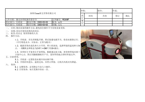
检印:时间内容修订确认4.1、开机前,首先用锁匙开锁,然后接通电源开关,检查水箱指示灯。
(开灯则是水少,应加水,正常为熄灭)
4.2、根据首饰在成色和大小不同,焊口的深浅,选择焊接的温度和大细点,一般K黄金和铂金为240℃--260℃用15-18点。
4.3、补焊时左手拿货右手拿焊线,眼睛通过放大镜,把货和焊线对准十字架中心点,然后用脚踏脚制开产关,需补焊的地点即时焊接完毕。
五、注意事项:
5.1、开机前一定要检查水箱冷却水够不够。
5.2、开机时间进长,温度过高,应停止焊接,让机内风机对内降温。
六、 保养:
6.1 定期保养:必须指定专业人士操作。
一、 目的:规范设备的操作方法,避免因打操作不当导致设备受损.二、 范围:其允许使用范围内的项目.
深圳市xxx珠宝首饰有限公司
6.2 日常保养:每月更换冷却水一次。
三、 权责:经认定 使用资格的人员.
四、 操作方法;
审核:
作成:改订履历文件名称:激光补焊机操作指导书
文件编号:WI009F 制定部门:行政部制定日期:2005-05-05
版本:A/0发行部门:行政部发行日期:2005-05-05
页数:1/1。
IPG激光器控制卡使用说明书

USBLMC_CUH_IPG_V1(4)USBLMC Client Use HandbookIPG BoardCatalogSafety During Installation And Operation (1)Summarize (2)Ways to differentiate modules (3)I.Functions of Fiber Module(IPG)and Definitions of Pins (3)1.Features (4)2.Output Socket Definitions (4)3.Definition of Output Socket Pin (5)a.CON1:DB15Galvo Output (5)b.CON2:DB25Fibre socket (6)c.CON3:DB9Marking-on-fly Encoder (7)d.CON4:DB15Power (8)e.CON5:IDC10Socket (10)4.Jumper Illustration (11)5.Hardware Connection (13)a.Input signal IN0,IN8,Start,EMSTOP (13)b.Input signal IN5,IN9 (13)b.Power Connection (14)c.Typical Connection of Fiber Laser Module (16)II.The common connection ways (16)1.The connection between User-defined digital Galvo conversion board&USBLMC control card (16)2.The encoder,photoelectric switch during marking-on-fly (18)Safety During Installation And OperationPlease read these operating instruction completely before you proceed with installing and operating this product.If there are any questions regarding the contents of this manual,please contact BJJCZ.1.Steps For Safe Operation�Carefully check your application program before running it.Programming errors can cause a break down of the system.In this case neither the laser nor the scan head can becontrolled.�Protect the board from humidity,dust,corrosive vapors and mechanical stress.�For storage and operation,avoid electromagnetic fields and static electricity.These can damage the electronics on the product.For storage,always use the antistatic bag.�The allowed operating temperature range is25℃±10℃.�The storage temperature should be between–20℃and+60℃.ser Safety�This product is intended for controlling a laser scan system.Therefore all relevant laser safety directives must be known and applied before installation and operation.Thecustomer is solely responsible for ensuring the laser safety of the entire system.�All applicable laser safety directives must be adhered to.Safety regulation may differ from country to country.It is the responsibility of the customer to comply with all localregulations.�Please observe all laser safety instructions as described in you scan head or scan module manual,and this manual.�Always turn on the power of this product and the power supply for the scan head first before turning on the laser.Otherwise there is the danger of uncontrolleddeflection of the laser beam.We recommend the use of a shutter to prevent uncontrolled emission of laserradiation.SummarizeUSBLMC marking control card is developed specially for marking machine,it adopt USB interface BLMC marking control card is made up of two PCB board:Main-board and IO board.Main board and IO board are connected by two sockets which with50pins.The main-boards are the same,the IO board is divided into three different kinds by application:Optic fiber module(IPG),common digital module,and common analog module.Among them,common digital module is with a conversion board.Features of USBLMC�PowerUSBLMC marking control card uses5V power.We suggest adopt the power of5V/3Ato achieve power mon digital module,common analog interface’s powerinput signal is on CON2socket of module;and the power input signal of the optic fibermodule is on CON4socket of module.Please check the corresponding instruction ofPINS.�The laser Control1)Offer3routes TTL signal:Laser Gate,PWM,FPK for laser ser Gatesignal used for controlling switch of laser;PWM signal can be regarded as PWMsignal in CO2laser machine or the repeated pulse frequency in Nd:Yag lasermachine;FPK is for the first pulse inhibits signal in YAG laser machine.2)Offer2routes that are used for controlling the power of the laser power supply andrepeated pulse frequency of Q switch.3)As to the YLP series of pulse optic fiber laser machine of IPG,which is supplyspecial control signal.4)Laser Gate,PWM signal can be set up into high level available or low levelavailable.5)Common digital module,common analog module can be used for pre-setting theoutput power of the laser power supply.�Common digital input/output signal(TTL signal)There are10routes input and7routes output mon digital signal is dividedinto two kinds,switch form of input signal(no need external power)and non-switchform of input signal(external component entities supply the electric current drive).Common output signal is belong to TTL output(Without optical-isolation),the maxoutput electric current is15mA.Note:"The inputs/outputs signal"of this manual are all for USBLMC control card.The signals receiving by the USBLMC and driving by external component is inputsignals;signals driving by USBLMC control and receiving by external component isoutput signals.�Support multi-card working pattern.One computer can control8sets of USBLMC at a time,makes and marks the control board to run side by side and operate.Differentcontents can be processed by8sets of control cards.�Marking-on-flyFlying encoder can be connected to do real-time liner speed checking for good result ofhigh speed marking.�Extend axis(step motor/servo electrical motor)outputCan output two directions/pulse signals of channels to control step motor(or servoelectrical motor),applicable to pivot or join.�Start signalUsed when marking contents are the same and high speed is required.The Floor pushcan connect to Start signal,or to the common input signal as well.If there are variablesin marking content,they have to be connected to the common input signal.�Compatible with USB2.0/USB1.0Ways to differentiate modulesThere are some texts at the right-bottom corner of the er can differentiate them by them.The contents are:I.Functions of Fiber Module(IPG)and Definitions of PinsEach module is developed according the different applications.Therefore,its serial number,pin definition,jumper setting,and functional settings can vary.When in use please make sure to refer to the instructions of each particular type of module.For example,5V power input signal of USBLMC,on the common digital module and common analog module,should be inserted from12/13/24/25of the feet on CON2socket;while on the optic fiber module,the power input signal is connected from4/5/12/13of the feet on CON4 socket.1.Featuresa).Specially set for the YLP pulse laser by IPG Company.CON2-DB25pin is directlyconnected with the laser cube’s25-stitch pin.b).Digital IO signal,with1-way common output and3-way common input signals.IN0/IN1are fixed as the input at fiber laser status;IN6as the emergency-stop signal input for fiber laser.IN7is to check whether the power of laser marking machine is turned on or off;IN2/3/5are not applicable.IN4/8/9are comment input signals.For specific connections and the suggested connections,please see the section“Digital IO Connection Instructions”.OUT0is the common output;OUT2s fixed as the red light of fiber laser;OUT3is fixed as laser enabled.OUT1,and OUT4~6are not used.c).Output X-axis step motor to control signals.Y/Z axis cannot be output.d).Connect rotary encoder for high speed marking.e).Galvo output signals are digital outputs and can be set as non-encoded digital signal outputs,or set as digital signal outputs with extend codes.2.Output Socket DefinitionsFig.1-1Fiber Module–Socket Illustration3.Definition of Output Socket Pina.CON1:DB15Galvo OutputGalvo signals are digital signals which can be directly connected to digital Galvo.Digital galvo’s signals transfer protocols are not exactly the same,therefore,it should be confirmed which type of transfer protocols is used by the digital galvo.The company also provides transfer boards,which are analog boards transferred from digital.It can also be transferred analog signal outputs and connected to analog galvo.Fig.1-2CON1of Fiber IO boardPin No.Signal name Illustrations1,9CLK-/CLK+Clock signal.Difference output2,10SYNC-/SYNC+Synchronized signal.Difference output3,11XChannel-/XChannel+Digital signal of X axis galvo.Difference output4,12YChannel-/YChannel+Digital signal of Y axis galvo.Difference output5,13ZChannel-/ZChannel+Digital signal of Z axis galvo.Difference output6,14Status-/Status+The state feedback signal of Galvo.Difference input8,15Gnd The reference ground of control card.For the common two-dimension Galvo,only connecting CLK,SYNC XChannel,Ychannel four groups with8signal lines is enough.We suggest use twisted-pair(such as net-line)for connecting for digital signal.b.CON2CON2::DB25Fibre socketCON2socket and optic fiber25stitch socket of laser instrument connect through25stitch rows of line directly.Fig.1-3Pins of CON2Pins Signal name Illustrations1——8P0——P7Laser power.TTL output.9PLATCH Power latch signal.TTL output.10,14Gnd Control card’s Ground11,12Ver2:GND Control card’s Ground Ver3:SGIN2,SGIN3Laser status input.13,15,24Ver2:GND Control card’s Ground Ver3:NULL Reserved16,21SGIN4,SGIN1Laser status input.17Vcc5V power output of control card.18MO Master Oscillator switch.TTL output 19AP Power amplifier.TTL output.20PRR Repeat pulse power signal.TTL output.22Out2Laser’s red light indication signal.TTL output.23EMSTOP Emergency stop signal.TTL output. 25NULL Reservedc.CON3:DB9Marking-on-fly EncoderFig.1-4Pins of CON3PIN No.Signals Illustrations1IN8Common input signal8.Forms a return circuit with GND9. To use this signal,connect it and GND respectively to either terminals of power.2,6IN9+/IN9-TTL input signal.Internal1K current-limited resistor. External current-limited resistor is suggested when voltage is over12V.Please refer to IN9Port Illustration.3,7BCODEN/BCODEP Encoder phase B input signal.Differential input. 4,5ACODEN/ACODEP Encoder phase A input signal.Differential input. 8Vcc Control card5V output.9Gnd Control card Ground.As the return circuit signal of pin8& 1.d.CON4:DB15PowerFig.1-5Fiber Interfere Board CON4Socket Signals and the definitions PIN No.Signals Illustrations1SGIN0Common input signal0.Forms a return circuit with ground 12and13of the control board.To use this signal,connect it and the ground respectively to either terminal of the power.This is an input signal.2EMSTOP Emergency-stop signal.Forms a return circuit with ground 12&13.To use this signal,connect it and the ground signal respectively to either terminal of the NORM-OPEN switch.When this EMSTOP is pressed,it means there is emergency and operation is immediately stopped.The signal is an input signal.3Ver2:POW_BTN Power signal of the laser instrument main power source. Forms a return circuit with the Ground12&13of the control board.To use this signal,connect it and the Ground signal respectively to either terminal of the NORM-OPEN switch.When the power button is pressed downward,pin 10&11are connected;when the button is bounced upwards,they are disconnected.For the power connection, see“Power Connection”.This is an input signal.Ver3:NULL Reserved4,5VCC5V input power positive terminal.This is an input signal.8START Start signal.Forms a return circuit with Ground12&13. To use this signal,connect it and the Ground signal respectively to either terminal of the power.This is an input signal.9OUT0Common output es GND12&13signals as reference signals.This is an output signal.10,11Ver2:POW_CON,POW_CON1Connection port of power relay.Connect POW_CON to theanode of power relay’s control power.One of the powerrelay’s control ports should be connected withPOW_CON1,and the other to the cathode of the cathode ofpower relay’s control power.When the3-point power isplugged in,POW_CON and POW_CON1are connected.At that time,power relay’s control port is connected to itscontrol power,power relay picks up,and fiber laser mainpower is on.Please see“Power Connection”for reference. Ver3:NULL Reserved12,13Gnd 5V input power cathode(Ground signal),i.e.the control card’s Ground signal.This is an input signal.6,14DIR-/DIR+Output signal.Direction signal of the extend axis(step motor or servo motor).The output mode could be set up either as differential output,or as level output(TTL output).This is an output signal.7,15PUL-/PUL+Pulse signal of extend axis(step motor or servo motor). The output mode could be set up either as differential output,or as level output(TTL output).This is an output signal.e.CON5:IDC10SocketFig.1-6CON5Socket PIN No.Signals Illustrations 1,2,3,4OUT5/4/6/1Common output signal es GND 5&7signals as reference signals.This is an output signal.5,7GND Ground 6,8NULL Reserved 9,10S45GND,SGIN5Common input signal 5.4.Jumper IllustrationFig.1-7Illustration of Fiber Interface board Module Jumper Location See jumper illustration below:Label NO.IllustrationsJP1,JP23Extend axis direction/pulse signaling set up.JP1set direction,JP2set pulse signal.Short connection to pins 1-2of jumper will makedifferential output of direction/pulse signal.CON4’s DIR-,DIR+,PUL-,PUL+should be respectively connected to step drive’sDIR-,DIR+,PUL-,PUL+.Short connection to pins 2-3of jumperwill make level output of direction/pulse signal.In this case,CON4’s VCC 、DIR+、PUL+should be respectively connected tostep drive’s VCC,DIR,PUL.JP32If pin NO.3of CON4is not connected to power switch,thisjumper should be connected short.Here correspond to that thepower switch is push down always.For system that uses powerswitch,do not connect the jumper.JP42Not used.JP5,JP6,JP72Index numbers 0~7,used to differentiate various cards when manycards are working at a time.JP8-JP7-JP6correspond to binary b2,b1,b0.Short connecting JUMPER means b0,and not short connecting it means b1.JP92Short connecting the JUMPER means galvo data excludes expanded code(s).Not short connecting it means it contains expanded code(s).Default Settings:JP1~JP2:Short connecting pin2~3.Extend axis direction/pulse signals output level mode. JP3:Not connecting.JP4:Not connecting.JP5~7:Not connecting.JP9:Short connecting.Fig.1-8Fiber module(Fiber Laser Module)Jumper Default Settings5.Hardware Connectiona.Input signal IN0,IN8,Start,EMSTOPFig.1-9input interface SGIN0、IN8、Start and EMSTOPFig.1-110Recommended Connection for Common Input SignalOnly an external switch is needed,and the contact resistance of the switch should be under100Ω.b.Input signal IN5,IN9Common input signal IN9connection circuit and suggested connection are shown as in fig.1-11 and1-12.(CON5PIN10and PIN9for IN5)Fig.1-11Common Input Signal IN9connection Circuit IllustrationFig.1-12Recommended Connection for Common Input Signal IN9The external power supply needs proper input voltage to make sure the current is between 10mA ~15mA.When input voltage is over 12V,it is suggested that control carton connects current-limited resistor R1.Supposed the input current chosen is 12mA,then the input resistance R1is calculated as per the following formula:10001121×⎟⎠⎞⎜⎝⎛−=Vin R Ωb.Power ConnectionSee below fig.1-13for recommended power connection:Fig.1-13Recommended power connection wayWhen the power switch is on,the control card turns on the power relay,and the laser main power is connected to the fiber laser.Pin POW_CON and pin POW_CON1allow maximum current of500mA.c.Typical Connection of Fiber Laser ModuleFig.1-14Typical connection way of fiber interface boardFor the Floor push,it depends whether the rotary encoder needs connected.If the marking-on-fly function is not used,then there is no need to connect the rotary encoder.II.The common connection ways1.The connection between U ser-defined digital Galvo conversion board&USBLMC control cardCON1(Digital input signal socket):Connect User-defined digital Galvo conversion’s DB15with USBLMC control card’s DB15directly.Fig.3-1Connection of conversion boardCON2(Power socket):Connect the outside±15V power to the corresponding pin,the range of the voltage is[±12V—±15V],as the following figure(Fig.3-2)Fig.3-2Connection of Power supplyCON3/CON4(Galvo control signal):It’s divided into Single interface&Difference two connection ways,we should choose the most suitable connection way according the GalvoNote:Difference connectioninterface’’s.We suggest use connection’’s output voltage is twice of single interfacesingle interface connection.And while only confirmed the Galvo interface is Difference interface,we can consider to follow the Difference output way.The two connection ways are as following figure(Fig.3-3Single interface of Galvo;Fig.3-4The difference of Galvo)Fig.3-3Single interface of GalvoFig.3-4The difference of Galvo2.The encoder,photoelectric switch during marking-on-flyUSBLMC control card receives differential drive signal(eg DS26LS31type)of encoder;use CON3:DB9encoder and photoelectric switch socket of mark-on-fly.The connection as the following figure(Fig:3-5)Fig.3-5Connection of encoder and photoelectric switch。
激光焊接机操作方法

激光焊接机操作方法
激光焊接机操作方法如下:
1.开机前工作
检查激光焊接机电源,水循环是否正常,检查机器内设备气体链接是否正常,检查机器表面无灰尘、花斑、油污等。
接通电源,打开总电源开关,按顺序打开水冷机、激光发生器等,打开氩气阀门,调节好用气流量,输入当前要执行的工作参数,执行焊接操作。
2.设置参数
设置焊接机的参数,电流可以设置为50-400A0.1-20MS频率0-50,常见的是焊接部位周边有咬痕,采用激光空打的方式将焊接部位空打后盖住,防止咬痕的出现,光斑超过焊接位置(0.1mm)即可,正常焊接工件模拟参数可电流可以按照以下设置:90-120脉宽:4-6;频率5-10,但是要根据工件的材质与实际情况调整。
3.关机
退出程序,关闭激光发生器,按顺序关闭除尘机,水冷机等设备;关闭氩气瓶阀门,关闭总电源开关。
激光焊接使用说明
激光焊接使用说明
激光焊接是一种利用激光束对材料进行焊接的技术。
激光焊接具有高能量密度、高精度、高速焊接等特点,广泛应用于金属材料的焊接加工领域。
以下是激光焊接的使用说明:
1. 准备工作:首先,确定待焊接的材料类型和厚度,选择合适的激光焊接机器。
然后,确保焊接机器的工作环境清洁、稳定,并进行必要的校准和调试。
2. 材料准备:将待焊接的材料进行清洁、除油、除尘等处理。
对于不同类型的材料,可能需要进行预处理,如表面涂层、切割等。
3. 安全措施:在进行激光焊接时,务必佩戴防护眼镜,以防止激光对眼睛造成伤害。
确保工作区域没有其他人员进入或对焊接过程产生干扰。
4. 焊接参数调整:根据焊接材料和厚度的不同,需要调整激光焊接机器的参数,如功率、波长、焦距等。
通常,通过测试焊接样品来确定最佳参数。
5. 焊接操作:将激光焊接机器对准焊接部位,调整焦距和焊接速度,开始焊接。
保持稳定的手持或固定焊接头,保持均匀的焊接速度和焊接压力,以确保焊接质量。
6. 焊接质检:完成焊接后,检查焊缝的质量和强度。
如果需要,可以进行非破坏性测试或破坏性测试来验证焊接的质量。
7. 后续处理:根据需要,可以进行后续处理工艺,如抛光、清洗、热处理等,以达到所需的外观和性能要求。
需要注意的是,激光焊接是一项高精密度的工艺,对操作者的要求较高。
在使用前,务必熟悉和掌握激光焊接机器的操作手册,并在安全规范下进行操作。
激光焊接机操作指导书

激光焊接机
操作指导书
版次
A/0
页次
1/1
分发号
编写:
审核:
批准:
一目的
提高效率,降低物耗,使员工更能熟悉激光焊接机的操作。
二、适用范围
激光焊接机的操作人员。
三、操作步骤:
3.1打开总电源、打开制冷机电源、激光焊接机电源及氮气气阀;
3.2打开“激光焊接机锁”,将开机按钮按下;在机器屏幕的调试屏上按“选项”键,调到“ON”后,按确定键;
3.8关掉激光焊接机电源及制冷机电源;
四、注意事项
4.1操作时,戴好手套、防护眼镜、口罩、、工作帽;焊接1个样品OK后方可正式焊接;
4.2参数由专人调试,其他人不得调试;
4.3焊接时手不可接触焊缝和经过激光发射头下方,谨防烧伤;
4.4切勿触摸刚刚焊接完的焊缝,防止烫伤;
4.5作业中如有意外立即按下急停开关并通知上级处理;
3.3待听到“嘭”声后,屏幕右侧的预燃Ⅰ、预燃Ⅱ指示灯亮起,按选项键选择“DEL”选项,按编程键选焊接程序;
3.4将电芯固定在夹具上,将控制板上的“校正”按下,进行对光,调节工作台高度,使激光发射头距焊点10mm左右,调节工作台前后位置,使光点正对焊缝;将氮气喷嘴正对焊点;
3.5关掉控制板上的“校正”,按动脚踏开关进行焊接操作;焊接的电芯及待焊接电芯须整齐摆放在中转盒中;
3.6按调试屏上的“选项”键,选择“DEL”选项,按“编程”键,选择保存的程序编号,按“确定”键后,按“选项”键设定电流及脉宽参数,按“确定”后,设置“频率”,最后连续按“确定”键,待听到“嘀”的一声后设置完成;开始焊接操作;
3.7按调试屏上的“选项”键,选择“OFF”选项,按“确定”键,按下控制板上的开机键,关掉开机锁;
手持光纤激光焊接机说明书

Handheld F iber L aser W elding M achineMachine footprint1.0/1.5/2KW parameterspower1kw/1.5kw/2KWLaser Type Fiber laserCenter wavelength1080nm ±5Max Output Energy1kw/1.5kw/2KWModulation frequency1-20,000HZRed light indicates output power0.5~1Fiber Cable length8mFiber Core Diameter50μmTotal Power Consumption7.5kw(1kw laser source)8.5kw(1.5kw laser source)10KW (2KW laser source) Rated Power220±20% V AC、50/60Hz(1KW/1.5KW)380±20% V AC、50/60Hz(2KW) Cooling Method Water CoolingGross Weight324kg(GW)Machine Dimension (L*W*H)625*1090*1746mmW elding thickness and melt depthItems Thickness Material Power Welding PenetrationMaximum MaterialWelding MaximumMaterialStainless steel 1000w 3mm 4mm 1500w 4mm 5mm 2000w 5mm 6mmGalvanized sheet 1000w 2mm 3mm 1500w 3mm 5mm 2000w 3mm 6mmIron 1000w 3mm 5mm 1500w 4mm 6mm2000w 4mm 6mm Mild steel 1000w 3mm 5mm 1500w 4mm 6mm2000w 4mm 6mm Aluminum 1000w 1mm 2mm 1500w 2mm 3mm2000w 3mm 4mm Brass 1000w 1mm 2mm 1500w 2mm 2mm2000w 2mm 3mmLaser welding head:Hanwei brand : 0.8KGWSX brand: 1KGQilin brand:1.26KGXH 0.9KGHanWei WSX brand Qilin brand XH brandPicturesWeight (KG )0.8 1.37 1.260.9weld methodspot size adjustable: 0-5MM adjustable: 0.2-4 mm adjustable: 0.2-5mm optional: 1.5/1.8/2MM wire size (mm) 0.8 1.0 1.2 1.6 (optional)0.8-1.20.8-1.60.5-1.6power 1000-2000 (Raycus, IPG, Max)1000-15001000-20001000-2000weld materialNormal material: Carbon steel, Stainless steel,Galvanized sheet High anti-material: aluminum, copper (not suggest)Welding wires type: auto feeding wires and manual feeding wires The auto feeding wire is a device as shown in the following pictures, which can automatically fill the welding wire while welding;T he manual type is held by hands without additional device.Wire selection: solid wire, no need core needed, diameter 0.8-1.2MM (customer matching according to the thickness of the plate welded by himself)The inner diameter of the reel is 6.6CM, and the outer diameter is ≤30CM (there is a reel in the wire feeder, and the customer can move it to the reel in the wire feeder after buying the wire)The relationship among laser spot, welding wires and welding line(gap) Laser spot > welding wire > welding lineEg.: 0.5mm welding line should use 0.8mm welding wire, but can not use 0.3mm welding wire. Which kind of welding wires should we choose which is depends on which kind of material you want to weld.When we use auto feeding wire system, the welding wire must be in the middle of the laser spot. This divide the laser spot into two halves automatically and stick to the seam of the welding head.Feeding device user manualThis feeding systm have stable feeding function, with strong anti-jamming. Can feeding 0.8mm, 1.0mm, 1.2mm wire. 1mm wire and 1.0mm, 1.2mm scroll wheel feeding as standard, Read the following for details.Configuration listNO Name Qty Remark1Feeding device(Without feeding tray)12The handheld nozzle trave (With screw).1Handheld parts 3Wire feeding mouth1Handheld parts 4Fixed attachment of wire feeding mouth(With screw)1Handheld parts 5 Power line (With plug)16Feeding ON/OFF switch ( With plug)17Umodel and internal corner feedingnozzle18Schematic diagram1A:The feeding main device – a. Installation parts: Nozzle trave, feeding mouth, fixed attachment ofwire – bser safety, operating safety announcementPl ease consider the following when operation setup1)Please correct install system by picture. Do not damage power supply and tread, twist, pull the electric cable. Cable damage can cause electric shock, short circuit, on fire.2)When smells of burning, abnormal noise, abnormal heating, up in smoke and other abnormal phenomena, please turn off the power supply and stop operating, otherwise cause the electric shock, on fire and other risk.3)In the feeding device should not foreign materials, especially the metal and conductive objects, in order to prevent short circuit and other faults. Do not use in a wet environment, Electric part contact with water may cause an electric shock or short circuit. When not working, please do not turn on power.2.Installation and operation1)Feeding structure setup, the first step is setting the handheld nozzle trave as 2a picture : The second step is setting feeding mouth on the trave as 2b picture : The third step is setting wire tray (Feeding – wire feeding – feeding mouth fix the connect–feeding mouth).The fourth step is fix all of parts by 2c picture.In the standby mode, 1 pin plus, 2 pin minus, when input DC15-24v driving the feeding. Here contact with gas signal of laser board. Power switch as picture 3.3)Face panel operation : As picture 4,Manual Feeding, when press the button wire is feeding.Manual Wire-back, when press the button, the wire feeding back direction.Wire-back Speed Adjust, rotate by clockwise direction to add pullback time of stop feeding. The back-feeding length and speed is directly proportional. When speed is slow, the back-feeding length is short. Opposite, when speed is quickly, the back-feeding length is long.Feeding Speed, adjust wire feeding speed.Power indicator, The light went on when turn on the power switch.Notes : Setting Ramp down time when over feeding. Lift handheld touch when release the button. If the welding is not continue, should resize well the feeding mouth.Wire feeding need compress tightly the nozzle and pull.2 The back-panel wiring installation diagram 3.AC220IN inputas picture 3a : Feeding swith as 3b picture.GAS:Argon and nitrogen.For the materials that are easily oxidized, it is better to use argon.Safety protection:We can choose safety protection from this system.The clip and the welding head have to touchthe same material at the same time,then laser will come out. This can protect operator.Hand-held Welding VS Traditional Electric Welding?PROGRAM TRADITIONALWELDING LASER WELDING HAND-HELD WELDINGHeat Input High Low LowDeformation, Undercut Series Slight SlightBond Strength Normal Good ExcellentFollow-up Program Polishing Hardly Ever Hardly EverSpeed Ordinary More than 2timesargonarc welding More than 2times argonarc weldingApplicable Material Stainless Steel,Carbon Steel,Galvanized SheetStainless Steel,Carbon Steel,Galvanized SheetStainless Steel, CarbonSteel, Galvanized SheetConsumables More Less Less Operation Difficulty Difficult Normal Easy Operator Safety Unsafe Safe Safe Environmental Protection Un-environment Environment Environment Welding Fault Tolerance High Low High Swing Welding Can’t Can’t CanSpot Width Unable Unable Adjustable Welding Quality Less Normal ExcellentSpare parts: Nozzle and Protective lens:In general, it can use 4-7 days, but it depends on operator and environment.If use auto feeding function, in general we need change lens by one week. Ifwe use manual type, the using time will less 7 days.wire feeding maunalHow to ensure the safety of handheld welder?You may know the TIG and MIG, we have many customers now use fiber to replace the TIG or MIG because of the effectiveness. And the safety almost the same as them but less spark.*Working methods The system includes safety protection, and the laser will work only when the clip and the welding gun contact withmetal at the same time, which can protect the safety of the operator.*High temperature resistant glovesWhen you use the machine,please wear gloves for double safe.*Goggles Machine come with Goggles for eye protection,we consider every details for customers :)And the operator will be like this in the video:https:///watch?v=LZXE_Dce-78Welding needs to adjust the light to the focus. The welding effect is the best and safety is the highest. It can avoid the sparks caused by strong light and can also extend thelife of the protective lens.The focal length of the welding head is about 150MM, so the range beyond 30CM of the welding head is safe, so please set a safety warning line for the 30CM near the operating table.Control panel:Machine Pictures:Westermans International LtdUnit 4 Midland Distribution Centre Markfield Road, Groby Leicestershire, LE6 0FS**********************Tel:+44(0) 116 2696941。
IPG高功率激光器客户培训说明材料V3
3.1 开启激光前提................................................................................................11 3.2 手动操作........................................................................................................13 3.3 手动模式使用激光编程...............................................................................14 3.4 外部调制模式................................................................................................15 3.5 模拟量控制模式............................................................................................17 3.6 硬线模式.......................................................................................................19
分钟,温度控制在 20-22℃之间。 6. 去离子水,电导率小于 10 微西门子,最佳流量 1.5 升/分钟,温度控制在 28-30
激光焊接使用说明
激光焊接使用说明
1. 安全操作:在使用激光焊接设备之前,操作人员必须接受专业培训,并严格遵守相关安全规定。
在操作过程中,应佩戴适当的防护设备,如护目镜、手套等,以防止激光辐射对人体造成伤害。
2. 设备准备:检查激光焊接设备的各个部件是否正常,包括激光发生器、光路系统、控制系统等。
确保设备处于良好的工作状态。
3. 材料准备:根据焊接需求,选择合适的材料,并对其进行预处理,如清洗、除锈等,以提高焊接质量。
4. 参数设置:根据材料的特性和焊接要求,设置合适的激光功率、焊接速度、光斑大小等参数。
这些参数的设置将直接影响焊接质量。
5. 焊接操作:将预处理好的材料放置在焊接工位上,启动激光焊接设备,进行焊接操作。
在焊接过程中,操作人员应密切关注焊接情况,如有异常应及时停止焊接。
6. 质量检查:焊接完成后,对焊接部位进行质量检查,如外观检查、焊缝强度检查等,确保焊接质量符合要求。
7. 设备维护:定期对激光焊接设备进行维护保养,如清洁光路系统、检查电气连接等,以延长设备寿命和保证焊接质量。
总之,激光焊接是一种先进的焊接技术,使用时需要严格遵守操作规程和安全规定,以确保焊接质量和操作人员的安全。
ipg2000激光器说明书
ipg2000激光器说明书手持终端接口:这个接口插入位与前面板右侧的前面板端口,它可以用来显示激光工作是的状态信息,这个可伸缩的线可以伸展至两米,急停按钮将禁止激光发射。
主屏:手持界面将会会显示激光的错误信息。
当没有错误存在时,操作人员可以在主屏和设置屏幕之间转换。
主屏显示光的发射状态,能量水平,是否有内外设定点,和激光的温度。
当选择主屏时,操作人员可以按选F4键来开关激光的发射,按F2键将选择设置屏幕。
按下急停按钮可以在任何时候停止激光发射,目独立干屏幕。
急停按钮可以通过顺时针旋转来进行开启。
设置屏幕:设置屏幕显示调制状态和外部控制,操作者可以按F1来启用或禁用调制,外部控制可以通过按选F2来进行开启操作。
按F4将使主屏返回于操作者面前。
操作模式:除了面板控制和远程控制以外,还有三种操作设置:内部/外部控制、调制激光发射禁止。
这些操作设置可以在手持终端的设置屏幕上选择,这些选择在关机后不再保持。
内部/外部能量设置:激光能量设置可以选择内部或外部控制。
当选择内部控制时,激光能量设置可以通过手持终端或RS-232指令,具体的操作为;内部控制可以通过手持终端上的设置屏幕进行或发送“DEC”指令。
外部控制可以手持终端上的设置屏幕选择或发送“EEC”指令。
当选择外部控制时,后面板上的接口连接器提供了激光的能量设置。
请参阅接口连接器引脚部分,该引脚对外部(模拟)进行控制,通过该控制为接口连接器提供了电气分配和电压水平。
使用外部(模拟)控制,必须通过软件或手持装置选择模拟控制模式和调制模式。
在模拟控制模式时必须发送一个触发信号到调制输入脚。
调制设置:外部调制可以用手持终端上的设置屏幕来实现调制或通过发送“EMOD”指令,当调制得以实现,激光将随着调制信号开合,当激光发射打开时,其能量水平由内部/外部设定决定。
外部调制可以被取消通过手持终端上的设置屏幕或发送“DMOD”指令。
该部分为接口连接器提供了电气分配和TTL逻辑门电平。
激光焊接机安全说明
激光焊接机安全说明激光修补·焊接机安全说明1、认真阅读操作说明书,严格按操作规程运转机器,以确保设备和人身安全:2、激光焊机工作期间,切勿用眼睛正视激光束,也切勿让身体(如手)接触激光束,以免造成伤害;3、对设备操作、作业的时候,请穿材料为化纤以外的不易燃烧,皮肤露出少的衣服;4、操作人员工作时,必须佩戴防护眼镜;5、激光加工中,由于加工点会产生可见光和紫外线等。
这些光线可穿透保护眼镜,在加工中请不要直视加工点;6、由于激光加工可能会发生火灾,所以绝对不能再机器的周围放置易燃物品。
(石油、润滑剂、丙酮、废棉纱头等);7、激光管理区域内,禁止激光相关人员以外的人进入;8、注意保持环境及设备的清洁,光具座是本机的核心部分维护时必须特别注意;9、进行维护时,要定期跟换制冷水和操作照明灯;10、更换制冷水时请使用高纯度离子水(制冷水的电阻率是18MΩ/cm2),更换期间的基准为一个月一次。
冷却水更换步骤如下:①打开水箱上盖:②水泵同时从侧面的排水口抽出水箱内的水;③抽出水后,擦去箱内的污垢、沾液等;④装进新的制冷水,到水位线为止。
⑤再盖上水箱上盖。
11、对机器进行检修,一定要断电,且要确定储能电容器上的电荷已经泄放完了,方能进行,以免造成触电事故;12、如机器运行过程中,出现异常现象,则需断电(按下急停开关)检查。
13、该设备操作环境要求①电压是单相200~220V,容量6KW;②请在干净的环境中使用;③操作场所的温度为10~32℃;④操作场所的湿度为<60%。
(请在不结露的场所内使用)14、设备启动操作如下:①将控制装置背面的总开关调到On;②打开水箱的电源后,请确认水温。
(开始时水温设置为20~25℃);③确认急停开关打开,将控制装置的钥匙开关顺时针旋转后,请按下Power On;④确认画面左上角显示“Turnon”后,请安OK按钮。
(画面左上角显示的“Turnon”变成“Turnoff”后、大约1分钟如果再次响起确认的声音,设备已启动,进入了可操作状态)15、设备停止操作如下:①光标停在“turnoff”时、按下OK按钮,请将钥匙开关逆时针旋转;②然后将水箱电源调至OFF,机器运转停止;③最后将控制装置背后的总开关调至off。
- 1、下载文档前请自行甄别文档内容的完整性,平台不提供额外的编辑、内容补充、找答案等附加服务。
- 2、"仅部分预览"的文档,不可在线预览部分如存在完整性等问题,可反馈申请退款(可完整预览的文档不适用该条件!)。
- 3、如文档侵犯您的权益,请联系客服反馈,我们会尽快为您处理(人工客服工作时间:9:00-18:30)。
ipg激光焊接机的说明书
1、在电源发动后,请不要直接观看激光输出端口。
2、在装置激光和相关的零配件的时分要远离眼睛。
3、对激光光线供给了一个密封罩请确保设备是否适用贴在产品上的激光安全标签上注明的输入功率和波长规模。
4、请不要在漆黑的环境下运用设备,在固定光纤或许准直器的时分请必须关掉激光,假如有必要的话,请将输出功率调到最低,然后再逐渐升高。
5、在设备运转的时分请不要进行装置或许半途停止光纤或许准直器。
6、IPG激光器假如输出功率是经过一个防反光膜的镜头输出的,请确保是高质量的镜头并且是洁净的,准直器的镜头任何一头有尘埃都会直接导致镜头和激光器的损坏,请在功率较低的条件下查看光斑和红光的质量,之后再渐渐的升高激光功率。
7、激光的输入电压都是致命的,一切电缆的零配件,连接头都被认为是风险的设备的装置要配适宜当的接地电源,为了避免火灾的风险,请运用平等型号的保险丝。
在供电之前,请确保运用正确的电压。
8、在敞开电源之前,请运用指定的电压。
为了避免电路不稳定,请不要牵动机器外壳,否则会直接影响到设备质量。