布鲁克斯 流量开关
压差式流量开关安装指导书
IP54
× ;长度 0.75mm2 2
1000mm
高压侧接口:G1/4”
低压侧接口:7/16”-20UNF
( ) 1/4” SAE
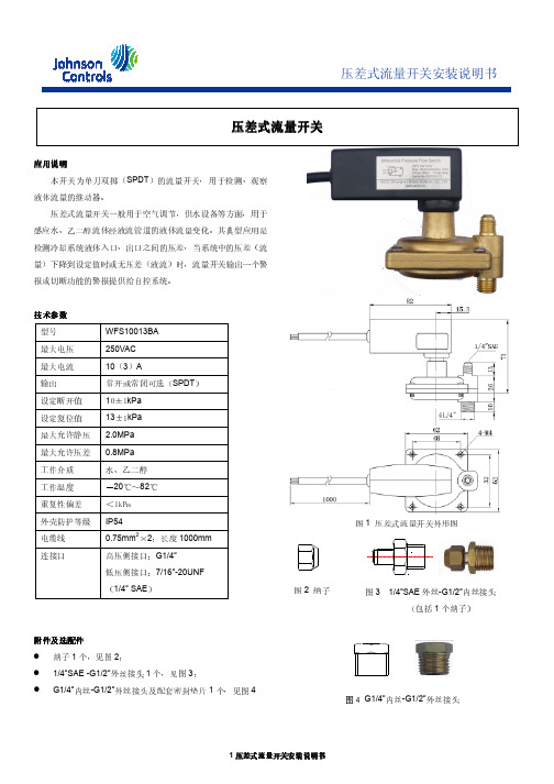
图 1 压差式流量开关外形图
图 2 纳子
图 外丝 内丝接头 3 1/4”SAE -G1/2” (包括 1 个纳子)
附件及选配件 纳子 1 个,见图 2; 1/4”SAE -G1/2”外丝接头 1 个,见图 3;
G1/4”内丝-G1/2”外丝接头及配套密封垫片 1 个,见图 4
内丝 外丝接头 图 4 G1/4” -G1/2”
1 压差式流量开关安装说明书
安装位置 合适的流量开关测压位置非常重要,有利于保证压差测量值
的准确性,选择测压位置应考虑一下几方面: 应尽量靠近换热器的进出水水管的上部作为测压口,不允许 从水管下部取压,避免垃圾进入测压管,进出水管两个测压 口之间的距离应尽可能短; 流量开关测压口与换热器之间不要有阀门等关断水流的装 置,以免影响其准确性; 流量开关的“+”端为 G1/4”外管螺纹必须接壳管换热器的 进水端,“-”端为 7/16”-20UNF 带喇叭口外管螺纹(通常 称 1/4”SAE)必须接壳管换热器的出水端; 两个测压口之间需要铜管连接,请考虑铜管走向,尽量躲开 可能出现人为损坏的位置,安装示意图见图 5。 如果冷水机组安装在室外,压差开关的安装位置对于冬天需 要放水的换热器(单冷机组),最好稍高于换热器的进水口 这样可以排出压差开关一侧的水。
的进出口之间不再有阀门等断流装置。
注意:安装前必须阅读压差式流量开关安装说明书,并请参照要求安装,如有疑问,请与当地最近的约克维修中心联系
2 压差式流量开关安装说明书
关输出触点允许通过电流阻性负载为 10A,感性负载为 。 3A
FS-200系列 直流通式流量开关 说明书
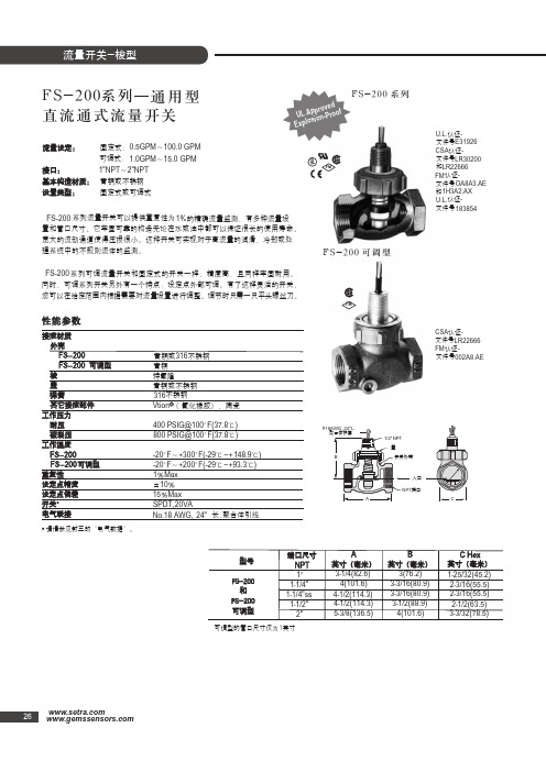
FS-200系列直流通式流量开关性能参数通用型流量设定:固定式:系列流量开关可以提供重复性为系列可调流量开关和固定式的开关一样,精度高,且同样牢固耐用。
同时,可调系列开关另外有一个特点:设定点外部可调。
有了这样灵活的开关,您可以在给定范围内根据需要对流量设置进行调整。
调节时只需一只平头螺丝刀。
可调式:青铜或不锈钢固定式或可调式的精确流量监测,有多种流量设置和管口尺寸。
它牢固可靠的构造无论在水或油中都可以保证很长的使用寿命。
宽大的流动通道使得压损很小。
这种开关可实现对于高流量的润滑、冷却或处理系统中的不规则流体的监测。
接口:基本构造材质:设置类型:接液材质外壳可调型青铜或青铜或不锈钢不锈钢长,聚合体引线型号和可调型可调型的管口尺寸仅为请情参见封三的“电气数据”。
英寸端口尺寸英寸(毫米)英寸(毫米)英寸(毫米)(氟化橡胶),陶瓷不锈钢青铜特氟隆工作压力耐压破裂压工作温度梭盖弹簧其它接液部件可调型重复性设定点精度开关电气联接0.5GPM ~100.0 GPM 1.0GPM ~15.0 GPM1"NPT ~2"NPT1%FS-200FS-200FS -200FS-200NPT 1"11-1/4"3-1/4(82.6)4(101.6)4-1/2(114.3)4-1/2(114.3)5-3/8(136.5)3(76.2)3-3/16(80.9)3-3/16(80.9)3-1/2(88.9)4(101.6)1-25/32(45.2)2-3/16(55.5)2-3/16(55.5)2-1/2(63.5)3-3/32(78.5)1-1/4"ss 1-1/2"2"AC Hex BFS-200FS -200FS -200316316Vtion 400 PSIG@100°F(37.8℃)800 PSIG@100°F(37.8℃)-20°F ~+300°F(-29℃~+148.9℃)-20°F ~+200°F(-29℃~+93.3℃)1%Max 15%Max SPDT,20VANo.18 AWG, 24"±10%FS -200FS-200系列FS-200可调型U.L.U.L.E31926CSA LR30200LR22666OA8A3.AE 1H3A2.AX 183854CSA LR22666FM 002A8.AEFM 认证-认证-认证-认证-认证-认证-文件号文件号文件号文件号文件号文件号和和FM入口 27订购指南-标准型号典型压降FS -200系列开关特殊的部件号是基于所需的外壳材质、管口尺寸和流量设定值而确定的,FS -200可调型还基于流量设定范围。
CF100L流量开关 说明书
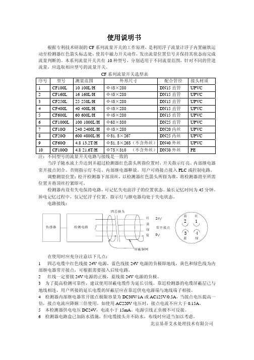
使用说明书根据专利技术研制的CF 系列流量开关的工作原理,是利用浮子流量计浮子内置磁铁运动至检测器红色箭头标志处,使其中磁力开关动作,发出流量位置信号并保持其状态而完成流量判断的。
本系列流量开关共有 10种型号,分别适用于不同流量范围,针对不同的管道流量,应选取相应型号的流量开关。
CF 系列流量开关选型表序号 型号 测量范围 外形尺寸 配合管径 接头材质 1 CF100L 10-100L/H Φ45×280 DN15直管 UPVC 2 CF160L 16-160L/H Φ45×280 DN15直管 UPVC 3 CF250L 25-250L/H Φ45×280 DN15直管 UPVC 4 CF400L 40-400L/H Φ45×280 DN15直管 UPVC 5 CF600L 60-600L/H Φ45×280 DN15直管 UPVC 6 CF1000L 100-1000L/H Φ68×380 DN25直管 UPVC 7 CF10G 240-2400L/H Φ45×280 DN20内丝 UPVC 8 CF20G 600-4800L/H Φ51.5×267 DN25内丝 UPVC 9 CF60G 4.8-13.2T/H Φ51.5×265(不含外丝)DN40外丝 UPVC 10 CF100G 4.8-21.6T/H Φ75×310 (不含外丝)DN50外丝 PE 注:不同型号的流量开关电路与接线是一致的当浮子随水流上升达到并超过检测器红色箭头所指位置时,开关指示灯亮、内部继电器常开接点闭合。
否则指示灯不亮、内部继电器释放。
用户可将接点接入PLC 或控制电路。
调整测量位置:松开检测器下部顶丝,以检测器红色箭头所指为准,将检测器滑至所需位置并将顶丝拧紧即可。
检测器内设有失电保持电路,可记忆失电前浮子的位置状态。
IFW5流量开关样本
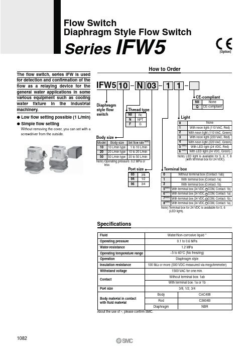
C3604B CAC408NBRAbout the use of , please confirm SMC.The flow switch, series IFW is used for detection and confirmation of the flow as a relaying device for the general water applications in some various equipment such as coolingwater fixture in the industrial machinery.# Low flow setting possible (1 L/min)# Simple flow settingWithout removing the cover, you can set with a screwdriver from the outside.Operating temperature range Water/Non-corrosive liquid0.1 to 0.6 MPa 1.2 MPa–5 to 60n C (No freezing)Diaphragm style100 M 7 or more (500 VDC measured via megohmmeter)1500 VAC for one min.Without terminal box: 1ab With terminal box: 1a or 1b3/8, 1/2, 3/4Rod BodyDiaphragmWater resistanceOperating pressure OperationInsulation resistance Withstand voltage Contact Port sizeBody material in contact with fluid materialFluid(LED light).How to OrderSpecificationsFlow SwitchDiaphragm Style Flow SwitchSeries IFW5[Option]1082Micro Switch Ratings ModelConstruction/Working Principle Flow CharacteristicsNote)Hysteresis is the flow rate that is necessaryfor moving the microswitch from theoperation position (ON signal) to the returnposition (OFF signal).Working PrincipleLiquid flow creates a pressure differential nearby the orifice of the port of the body:. One set of diaphragms monitors the pressure differential and operates themicro switch through the rod @ and operating lever ;.The rod @ moves downward with increased flow, and upward with decreased flow.Moving the gear = upward or downward by the adjusting gear . manually offersan electric signal at various flow rates.Adjusting gearGearFlow settingindication leverBodyRodOperating leverMicro switchProtection diaphragm1083Series IFW5Flow SwitchDiaphragm Style Flow SwitchPFMPFMVIFW5:0-::-10 to 24(With terminal box)DimensionsIFW5:0-::-00 to 04(Without terminal box)With neon lightLead wire length 500With neon lightSeries IFW510841085Series IFW5Flow SwitchDiaphragm Style Flow SwitchDimensionsIFW5:0-::-55 to 86(With light, Terminal box for 24 VDC)PFM PFMVB (NC)A (NO)C (COM)B (NC)A (NO)C (COM)AdjustingBe sure to read before handling.Refer to front matter 56 for Safety Instructions and pages 952 and 953 for Flow Switch Precautions.Caution1.Mount a switch, so that the liquid flow is in the same direction as that of the arrow on the body.2.Be sure to fill the passage with the fluid.3.The flow switch can be installed either horizontally or vertically.4.Provide a straight pipe portion that corresponds to approximate-ly 5 times the bore of the pipe before and after the area of the pipe on which the product is installed, thus keeping the product as far away as possible from the elements that disturb the flow, such as elbows or valves.5.For wiring, refer to the internal wiring diagram.6.If a terminal box is not available, wire by selecting the contact at 1a or 1b. At that time, insulate the lead wires that will not be used.7.Because this is an open style, it cannot be used where water or oil splashes.8.It cannot be used if a water hammer or pulsation pressure is ap-plied to the fluid.9.In order to prevent a malfunction or diaphragm damage caused by debris or cutting chips in the fluid, install a filter with approxi-mately 100 mesh on the inlet side of a flow switch.1. To adjust flow, remove grommet of the upper cover and rotate flow adjusting gear using a flat head screwdriver.Turning clockwise can increase the set flow and turning coun-terclock can decrease the set flow.2. The flow rate setting point is set at the ON flow rate. Therefore, in the case of the 1a contact, the ON signal is output if fluid with a higher flow rate than the set flow rate has occurred.In the case of the 1b contact, the ON signal is output when the flow rate has decreased from the set flow rate for the amount that corresponds to the hysteresis.3. To prevent the chattering that is associated with the fluctuation of the operating flow rate, set the difference between the set flow rate and the operating flow rate so that it is as large as pos-sible.4. Use at or below the maximum operating pressure and maximum flow rate.5. The indicator on the window name plate (Fig. 1) is only a guide-line. For precise setting, mount a flow meter on the downstream side of the flow switch, and set the level.Also, when setting levels with a low flow rate at pressures of 0.2 MPa or more, there may be interference between the indicator needle and the scale plate. In such cases, detach the indicator needle and scale plate before setting. After setting, the indicator needle and scale plate can be reattached in positions of your choice.Graduations for IN pressure 0.1 MPa Graduations foradjusting on flow rateGraduations for IN pressure 0.2 MPaFig. 1 Window name plateIFW5:0-::-00/10/20IFW5:0-::-01 to 04/11 to 14/21 to 24IFW5:0-::-55/56IFW5:0-::-65/66IFW5:0-::-75/76IFW5:0-::-85/86Internal Wiring Diagram1086Series IFW5。
卓然天工 FS580 581 582 583 584 流量开关 说明书
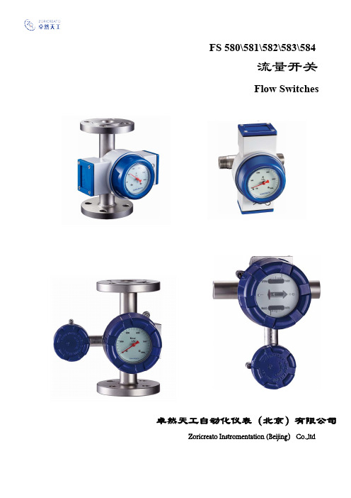
卓然天工自动化仪表(北京)有限公司 Zoricreato Instromentation (Beijing) Co.,ltdF S580\581\582\583\584流量开关Flow Switches一、概述F S58系列流量开关,可对各种液体流量进行监测和开关信号控制。
独特的结构设计,准确可靠的性能,广泛的应用于管道中大、中、小型设备的冷却、润滑系统中。
例如:发电机组、冷/热轧机、压缩机、轴封水、冷却系统等。
任意设置报警点/任意可调。
F S580系列/内管螺纹内管螺纹: 1/2". 3/4". 1-1/4". 1-1/2". 2". 2-1/2" 测量结构:锥管/靶式、喷嘴/靶式指示器形式:M1、 M2、M3、M4、M5流量开关设置:低流量报警/高流量报警;可独立选择低或高,也可同时选择低和高。
F S581系列外管螺纹: 1/2". 3/4". 1-1/4". 1-1/2". 2". 2-1/2" 测量结构:锥管/靶式、喷嘴/靶式指示器形式:M1、 M2、M3、M4、M5流量开关设置:低流量报警/高流量报警;可独立选择低或高,也可同时选择低和高。
F S582系列法兰:DN15 . 20 . 25 . 32 . 40 . 50 . 65 (口径)测量结构:锥管/靶式、喷嘴/靶式指示器形式:M1、 M2、M3、M4、M5流量开关设置:低流量报警/高流量报警;可独立选择低或高,也可同时选择低和高。
F S583系列法兰:DN80 . 100 .125 . 150 . 200 . 250 (口径)测量结构:锥管/靶式、喷嘴/靶式指示器形式:M1、 M2、M3、M4、M5流量开关设置:低流量报警/高流量报警;可独立选择低或高,也可同时选择低和高。
F S584系列(插入式)法兰: DN150 (口径)测量结构:靶式指示器形式:M1、 M2、M3、M4、M5流量开关设置:低流量报警/高流量报警;可独立选择低或高,也可同时选择低和高。
FCI流量开关

C
哈氏合金 C
D
D
蒙耐尔合金 400
E
-
W
W
6. 过程连接
2 级钛 系统认证,用户定义
-
1
1/4” MNPT
1
2
3/4” MNPT
2
3
1” MNPT
3
4
1” M BSPT
4
5
法兰
5
6
11/4” MNPT, 可在线插拔的密封套管, 低压 350 kPa(g) Max.
6
7
法兰, 可在线插拔的密封套管, 低压 350 kPa(g) Max.
7
8
11/4” MNPT, 可在线插拔的密封套管, 中压 3500 kPa(g) Max.
8
9
法兰, 可在线插拔的密封套管, 中压 3500 kPa(g) Max.
M
-
3/4” MNPT (2500 psig 二级压力密封)
C
-
3/4” MNPT,卡套连接,特氟隆卡环 1000 kPa(g) 93ºC max.
4
4
CSA 认证
5
5
6
6
3. 铭牌
A
A
B
B
W
W
4. 工作温度
CSA(T4 级) IEC Ex d IIC 认证
粘贴标签 标签和不锈钢铭牌 系统认证,用户定义
1
1
-40º ~+177ºC
2
2
-73º ~+260ºC
3
-
5. 全焊接材质
A
A
B
B
-73º ~+454ºC
316 不锈钢 316 不锈钢电镀
IO-Link数字流量开关操作手册说明书
Before UseDigital Flow SwitchPF3A703H/PF3A706H/PF3A712H-LSafety InstructionsThese safety instructions are intended to prevent hazardous situations and/orequipment damage.These instructions indicate the level of potential hazard with the labels of"Caution", "Warning" or "Danger". They are all important notes for safety and mustbe followed in addition to International standards (ISO/IEC) and other safetyregulations.OperatorThank you for purchasing an SMC PF3A703H/PF3A706H/PF3A712H-L DigitalFlow Switch.Please read this manual carefully before operating the product and make sure youunderstand its capabilities and limitations. Please keep this manual handy forfuture reference.Safety Instructions1324DisplayBody(IN side)Connector pin numbers(on the product)Mounting•Never mount the product in a place that will be used as a mechanical support during piping.•Never mount the product upside down.•Attach the piping so that the fluid flows in the direction indicated by the arrow on the body.•The monitor with integrated display can be rotated.Rotating the display with excessive force will damage the end stop.•Visibility decreases if the display is viewed from the opposite side to the buttons.Check the settings and display from in front of the display.Mounting and InstallationRefer to the product catalogue or SMC website (URL https://) for moredetailed information.IN OUTArrowthe IN side of the product.When installing a regulator at the IN side of the product, make sure that hunting is not generated.•The piping on the IN side must have a straight section of piping whose length is 8 timesthe piping diameter or more.If a straight section of piping is not installed, the accuracy will vary by approximately 3%F.S.•Avoid sudden changes to the pipingsize on the IN side of the product.The accuracy may vary.•Do not release the OUT side pipingport of the product directly to theThe accuracy may vary.○Flow direction○Rotation of the display•Use the correct tightening torque for piping. (Refer to the table below for the requiredtorque values.)•If the tightening torque is exceeded, the product can be damaged.If the tightening torque is insufficient, the fittings may become loose.•Avoid any sealing tape getting inside the fluid passage.•Ensure there is no leakage after piping.•When mounting the fitting, a spanner should be used on the body (metal part) of thefitting only.Holding other parts of the product with a spanner may damage the product.Specifically, make sure that the spanner does not damage the M12 connector.■WiringConnection•Connections should only be made with the power supply turned off.•Use a separate route for the product wiring and any power or high voltage wiring. If wiresand cables are routed together with power or high voltage cables, malfunction may resultdue to noise.•If a commercially available switching power supply is used, be sure to ground the frameground (FG) terminal. If the product is connected to the commercially available switchingpower supply, switching noise will be superimposed and the product specifications will notbe satisfied. In that case, insert a noise filter such as a line noise filter/ ferrite between theswitching power supplies or change the switching power supply to the series power supply.Connecting/Disconnecting•Align the lead wire connector with the connector keygroove, and insert it straight in. Turn the knurled partclockwise. Connection is complete when the knurledpart is fully tightened. Check that the connection is notloose.•To remove the connector, loosen the knurled part andpull the connector straight out.Connector pin numbers (lead wire)Outline of SettingsPower is supplied.∗: If a button operation is not performed for 3 seconds during the setting, the display will flash. (This is toprevent the setting from remaining incomplete if, for instance, an operator were to leave during setting.)∗: 3 step setting mode, simple setting mode and function selection mode settings will reflect on each other.■3 step setting modeIn the3 step setting mode, the set value selected in the sub display and the hysteresiscan be changed in just 3 steps.Switch ONP_1Flow[L/min]H_1settingsWhen shipped, the default setting is as follows.When the flow exceeds the set value [P_1], the switch will be turned ON.When the flow falls below the set value by the amount of hysteresis [H_1] or more, theswitch will turn OFF.If the operation shown below is acceptable, then keep these settings.For more detailed settings, set each function in the function selection mode.(1) Press the S button once when the item to be changed is displayed on the subdisplay.The set value on the sub display (right) will start flashing.S<Operation>[Hysteresis mode]In the 3 step setting mode, the set value (P_1 or n_1) and hysteresis (H_1) can bechanged.Set the items on the sub display (set value and hysteresis) using the ▲ or ▼ buttons.When changing the set value, follow the operation below. The hysteresis setting can bechanged in the same way.(2) Press the ▲ or ▼ button to change the set value.The ▲ button is to increase and the ▼ button is to decrease the set value.●Press the ▲ button once to increase the value by one digit, press and hold tocontinuously increase.●When ▲ and ▼ buttons are pressed simultaneously for 1 second or more, the setvalue is displayed as [ - - - ], and the set value will be set to the same as thedisplayed value automatically. Afterwards, it is possible to adjust the value bypressing ▲ or ▼.●Press the ▼ button once to reduce the value by one digit, press and hold tocontinuously reduce.(3) Press the S button to complete the setting.To change setting, refer to the operation manual from SMC website(URL https://) or contact SMC.<Operation>[Hysteresis mode](1) Press the S button for 1 second or longer(but less than 3 seconds) in measurementmode. [SEt] is displayed on the main display.When the button is released while in the [SEt] display, the current flow value isdisplayed on the main display, [P_1] or [n_1] is displayed on the sub display (left)and the set value is displayed on the sub display (right).(2) Change the set value using the ▲ or ▼ button, and press the SET button to set thevalue. Then, the setting moves to hysteresis setting.(5) Press and hold the S button for 2 seconds or longer to complete the simple setting.(If the button is pressed for less than 2 seconds, the setting will be returned to P_1.)(3) Change the set value with the ▲ or ▼ button, and press the S button to set thevalue. Then, the setting moves to the setting of OUT2.∗1: Selected items of (1) to (4) become valid after pressing the S button.∗2: After enabling the setting by pressing the S button, it is possible to return to measurementmode by pressing the S button for 2 seconds or longer.∗3: When the output mode is set to accumulated pulse, error output or output OFF, the simplesetting mode cannot be used.(the setting returns to measurement mode by releasing the button when [SEt] is displayed.)■Simple setting modeIn the simple setting mode, the set value, hysteresis and delay time can be changed whilechecking the current flow value (main display).(4) Like the setting of OUT1, the setting returns to the setting of OUT2 by pressing theS button after setting the set value and hysteresis.∗: When [F 1] and [F 2] are set to accumulatedpulse output, error output or output OFF [---]will be displayed in the sub screen when[SEt] is displayed. It is not possible to moveto the Simple setting mode.Change the Function Settings∗1: Setting is only possible for models with the units selection function.∗2: [F 2] The OUT2 setting can be set on the product screen, but since there is no OUT2 switch outputfunction as an output specification, it is not possible to output the ON/OFF signal to an external device.∗3: When the 1 switch output type (output specification symbol is L) is used, [F5] is displayed as [---]and cannot be set.1 to 5 V or 0 to 10 V can be selected when the analogue voltage output type is used.Analogue output free range function can be selected.∗4: When Line name is selected, a suitable line name can be input.To change setting, refer to the operation manual from SMC website(URL https://) or contact SMC.■Function selection modeIn measurement mode, press theS button for 3 seconds or longer,to display [F 0].The [F] indicates the mode forchanging each Function Setting.Press the S button for 2 secondsor longer in function selectionmode to return to measurementmode.To change setting, refer to the operation manual from SMC website(URL https://) or contact SMC.○Reset operationThe Accumulated Flow, Peak Value and Bottom Value can be reset.To reset the accumulated value, press the ▼ and S button for 1 second or longer.○Snap shot functionThe current flow rate value can be stored to the switch output ON/OFF set point.When the items on the Sub display (left) are selected in either 3 step setting mode, Simplesetting mode or Setting of each function mode, by pressing the ▲ and ▼ buttonssimultaneously for 1 second or longer, the value of the sub display (right) will show "----",and the values corresponding to the current flow rate are automatically displayed.MaintenanceHow to reset the product after a power loss or when the power has beenunexpectedly removedThe settings for the product are retained in memory prior to the power loss or de-energizingof the product.The output condition is also recoverable to that prior to the power loss or de-energizing.However, this may change depending on the operating environment. Therefore, check thesafety of the whole installation before operating the product.If the installation is using accurate control, wait until the product has warmed up(approximately 10 to 15 minutes) before operation.Refer to the product catalogue or operation manual from SMC website(URL https://) for more information about the product specifications anddimensions.Specifications / Dimensions○Key-lock function(1) Press the S button for 5 seconds or longer in measurement mode. When [oPE] isdisplayed on the main display, release the button.The current setting "LoC" or "UnLoC" will be displayed on the sub display.(2) Select the key locking/un-locking using the ▲ or ▼ button, and press the S button toset.To use each of these functions, refer to the operation manual from SMC website(URL https://) or contact SMC.The IODD file can be downloaded from the SMC website (URL https://).Note: Specifications are subject to change without prior notice and any obligation on the part of the manufacturer.© 2020 SMC Corporation All Rights ReservedAkihabara UDX 15F, 4-14-1, Sotokanda, Chiyoda-ku, Tokyo 101-0021, JAPANPhone: +81 3-5207-8249 Fax: +81 3-5298-5362URL https://PF※※-OMX0003Troubleshootingdisplayed, please contact SMC.Refer to the operation manual from SMC website (URL https://) for moreinformation about troubleshooting.。
FS-580高品质靶式流量开关
维修时提醒操作人 员, 保证部件在最
佳 的 工 作 环 境 下 正 常 运 行 。Ga. e s c T 另 有 一 种 可 选 配 的 “ 护 锁 ”装 置 , 维 P 1 新 一代 的 激 光 颗 粒 计 C 3 2是 数 器 , 优 化 压 缩 空 气 或 压 缩 气 体 系 为 统 提 供 依 据 ,可每 周 连 续 7天 , 天 每 连续 2 4小 时 工 作 。对 于 03 m 颗 粒 .g 的 测 量 灵 敏 度 ,P 1 C 3 2达 到 了 IO S 87 . 5 34压缩 空 气 标 准 所 规 定 的 需 求 。 显 示 的 测 量 值 代 表 每 立 方 米 压 缩 气 体 中 的 颗 粒 数 , 测 量 值 每 分 钟 更 新 该
一
检测仪未经校 准, 就无法在相关场所
读者 服务 卡编号 0 1 4 口
正常使用 。
这种 新 一代 型号 采用 科尔 康独 创的 Ga. e 引擎 ”探测方法 ,己 s c“ T
一
通 过 行 业 认 证 , 证 适 用 , 足 严 保 满
的 日常使用标准 。Ga.e s c响应时 间 T
成 的 US 端 口或 通 过 可 选 的 以 太 网 B ( ten t Eh re)或 RS 8 4 5接 口传 输 到 个 人 电 脑 上 。 针 对 数 据 分 析 和 报 表 生
0 1,0 p m,误 差值 在± O — 00 0 p 1 %以 内 。 电池 使 用 时 间超 过 2 h 2 ,可 满 足 单 班 不间断连续检测 。 电池 充 电时 间 仅 需
以满 足 车 速 在 3 k g以 内 时 进 行 检 0 m/ 测 。 用 各类 特 定 用 途 的探 头 也 有 供 适
PF3WB PF3WC PF3WS PF3WR数字流量开关-多功能型说明书
Page 1 of 3Instruction ManualDigital Flow Switch – Manifold type PF3WB / PF3WC PF3WS / PF3WRThe intended use of thedigital flow switch manifoldis to monitor and adjust fluid flow to a device while connected to the IO-Link protocol.These safety instructions are intended to prevent hazardous situations and/or equipment damage. These instructions indicate the level of potential hazard with the labels of “Caution,” “Warning” or “Danger.”They are all important notes for safety and must be followed in addition to International Standards (ISO/IEC) *1), and other safety regulations. *1)ISO 4414: Pneumatic fluid power - General rules relating to systems. ISO 4413: Hydraulic fluid power - General rules relating to systems.IEC 60204-1: Safety of machinery - Electrical equipment of machines. (Part 1: General requirements)ISO 10218-1: Manipulating industrial robots -Safety. etc.• Refer to product catalogue, Operation Manual and Handling Precautions for SMC Products for additional information. • Keep this manual in a safe place for future reference.CautionCaution indicates a hazard with a low level of risk which, ifnot avoided, could result in minor or moderate injury.WarningWarning indicates a hazard with a medium level of riskwhich, if not avoided, could result in death or serious injury.DangerDanger indicates a hazard with a high level of risk which, ifnot avoided, will result in death or serious injury.Warning• Always ensure compliance with relevant safety laws and standards.• All work must be carried out in a safe manner by a qualified person in compliance with applicable national regulations.• This product is class A equipment intended for use in an industrial environment. There may be potential difficulties in ensuring electromagnetic compatibility in other environments due to conducted or radiated disturbances.• Refer to the operation manuals on the SMC website (URL: https:// ) for more safety instructions.Warning• Special products (-X) might have specifications different from those shown in the following section. Contact SMC for specific drawings.2 Specifications2.1 Manifold Common Specifications2.2 IO-Link specifications (for PF3W7##-L flow switch)• Refer to the PF3WB Operation Manual and the Operation Manual for the PF3W7, PF3W7-L or PF3W5 series on the SMC website (URL: https:// ) for more Specification details.3.1 PF3WB type ManifoldPart DescriptionSupply(Supply unit)This unit supplies the fluid from the supply side main piping to the application.Flow adjustment valve and stop valve can be combined to comprise the equipment.• The supply unit is not suitable for a flow switch. Return(Return unit)This unit returns the fluid exhausted from the application.Flow adjustment valve and stop valve can be combined to comprise the equipment.Flow switch The flow switch displays or outputs the flow rate when flow is applied.• Applicable to integrated display type / remote sensor type (temperature sensor type can be selected).• IO-Link compatible (Integrated display type PF3W7##-L only).• Cannot be used for the supply unit.Display The integrated display type displays flow rate, set value and error codes.The remote type displays POWER indicator and FLOW indicator.For display, refer to the Operation Manual.(Display integrated type: PF3W7, remote sensor type sensor: PF3W5)Connector This is for connecting the lead wire.PartDescriptionLead wire with M8 connectorLead wire to supply power to and obtain output signals from the flow switchFlow adjustment valveOrifice mechanism to adjust the flow rate.• The flow adjustment valve is not suitable for applications which require constant adjustment of flow rate.• This valve is not suitable for stopping the flow. • Applicable to both the supply and return unit. Flow adjustment knob This knob is for adjusting the flow rate. Lock ringThis is used for holding the flow adjustment valve.Stop valveThis is the mechanism for stopping the flow rate. ∗: Not suitable for adjusting the flow rate. ∗: Applicable to supply/return unit.Stop valve handleThis handle is for stopping the flow rate. When the handle is rotated by 90°, it is possible to stop the flow rate.AttachmentTo connect the piping of the supply/return units. Main pipingTo connect the piping of the manifold body. Open or close cannot be selected.• PF3WC series is not applicable to “Close”. • It is not possible to change the main piping after ordering.ORIGINAL INSTRUCTIONSModel PF3WBPF3WCPF3WSPF3WRManifold specifications Integrated type Remote type Arrangement 1 to 10 stationSupply or Return: 1 to 5 station1 to 10 station1 to 10 stationU n i t Rated flow range 0.5 to 4 L/min, 2 to 16 L/min, 5 to 40 L/min Supply unit construction With flow adjustment valve / stop valve- Return unit construction Flow switch,flow adjustment valve,stop valve-Flow switch, adjustment valve, stop valveF l u i d Applicable fluid Water and ethylene glycol solution with aviscosity of 3 mPa •s(3 cP) or less Fluid temp. 0 to 90 o C (No freezing and condensation)P r e s s u r e Operating pressure range 0 to 1 MPa Proof pressure 1.5 MPaPressure loss Refer to graph for pressure lossE n v i r o n m e n tEnclosure IP65Operating temp. range 0 to 50 oC (No freezing and condensation)Operating humidity range Operation, Storage: 85%R.H. (No condensation)Materials in contact with fluidPPS, SUS304, FKMGrease free P i p i n g p o r tMain piping 1 inch Attachments 3/8, 1/2, 3/4 inch•The PF3WB type manifold is shown .The individual parts of the PF3WC, PF3WS and PF3WR are the same.4.1 InstallationWarning•Do not install the product unless the safety instructions havebeen read and understood.•Use the product within the specified operating pressure andtemperature range.•Tighten to the specified tightening torque.If the tightening torque is exceeded the mounting screws, brackets andthe product can be broken. Insufficient torque can cause displacementof the product from its correct position.•Do not drop, hit or apply excessive shock to the product.Otherwise damage to the internal parts can result, causing malfunction.•Do not pull the lead wire forcefully, and do not lift the product bypulling the lead wire (tensile force 49 N or less).4.2 EnvironmentWarning•Do not use in an environment where corrosive gases, chemicals, saltwater or steam are present.•Do not use in an explosive atmosphere.•Do not expose to direct sunlight. Use a suitable protective cover.•Do not install in a location subject to vibration or impact in excess ofthe product’s specifications.•Do not mount in a location exposed to radiant heat that would result intemperatures in excess of the product’s specifications.•Do not use the product in places where there are cyclic temperaturechanges.Heat cycles other than ordinary changes in temperature can adverselyaffect the inside of the product.4.3 Mounting•Never mount the product in a location where it will be used as a support.•Mount the product so that the fluid flows in the direction indicated bythe arrow on the product label or on the product body.•Check the flow characteristics data for pressure loss and the straightinlet pipe length effect on accuracy, to determine inlet pipingrequirements.•Do not sharply reduce the piping size.•The monitor with integrated display can be rotated. It can be set at 90ointervals clock and anticlockwise, and also at 45o and 225o clockwise.Rotating the display with excessive force will damage the end stop.•When a stop valve is mounted, rotate the monitor after closing the stopvalve handle.Rotating the monitor with excessive force with the stop valve open, themonitor and stop valve will interfere with each other, causing damage(refer to the figure below).4.4 Direct mounting (PF3W704 / 720 / 740)•When mounting the product, mount it to a panel with screws(equivalent to M6) using the mounting holes provided.•Mounting plate thickness should be approximately 3 mm.•Screws and nuts must be prepared by the user.The PF3WB uses 6 mounting screws, and the PF3WC, PF3WS and4.5 PipingCaution•Before connecting piping make sure to clean up chips, cutting oil, dustetc.•When installing piping or fittings, ensure sealant material does notenter inside the port.•Eliminate any dust left in the piping using an air blow before connectingthe piping to the product.•Ensure there is no leakage after piping.•When connecting piping to the product, hold the piping with a wrenchon the metal part of the piping (piping attachment) and main port of themain piping, which is integrated into the piping.•Using a spanner on other parts may damage the product.In particular, do not let the spanner come into contact with the M8connector. The connector can be easily damaged.After hand tightening, apply a spanner of the correct size to thespanner flats on the product, and tighten it for 2 to 3 rotations, to thetightening torque shown in the table below.If the tightening torque is exceeded, the product can be damaged. Ifthe correct tightening torque is not applied, the fittings may becomeloose.Nominal Thread size Tightening torque Width across flatsRc (NPT) 3/8 15 to 20 N•m 20.9 mmRc (NPT) 1/2 20 to 25 N•m 23.9 mmRc (NPT) 3/4 28 to 30 N•m 29.9 mmRc (NPT) 1 36 to 38 N•m 41.0 mm4.6 WiringCaution•Do not perform wiring while the power is on.•Confirm proper insulation of wiring.Poor insulation (interference from another circuit, poor insulationbetween terminals, etc.) can lead to excess voltage or current beingapplied to the product, causing damage.•Do not route wires and cables together with power or high voltagecables.Otherwise the product can malfunction due to interference of noise andsurge voltage from power and high voltage cables to the signal line.Route the wires (piping) of the product separately from power or highvoltage cables.•Keep wiring as short as possible to prevent interference fromelectromagnetic noise and surge voltage.Do not use a cable longer than 30 m. (IO-Link compatible device: 20m or less).•Ensure that the FG terminal is connected to ground when using acommercially available switch-mode power supply.•When an analogue output is used, install a noise filter (line noise filter,ferrite element, etc.) between the switch-mode power supply and thisproduct.4.7 Connector Wiring5 SettingsRefer to the Operation manuals on the SMC website(URL: https://) for the following Settings:Flow switch Setting and Function setting•Integrated display type: PF3W7•Integrated display type (IO-Link compatible): PF3W7-L•Remote type sensor: PF3W56.1 General MaintenanceCaution•Not following proper maintenance procedures could cause the productto malfunction and lead to equipment damage.•If handled improperly, compressed air can be dangerous.•Maintenance of pneumatic systems should be performed only byqualified personnel.•Before performing maintenance, turn off the power supply and be sureto cut off the supply pressure. Confirm that the air is released toatmosphere.•After installation and maintenance, apply operating pressure andpower to the equipment and perform appropriate functional andleakage tests to make sure the equipment is installed correctly.•If any electrical connections are disturbed during maintenance, ensurethey are reconnected correctly and safety checks are carried out asrequired to ensure continued compliance with applicable nationalregulations.•Do not make any modification to the product.•Do not disassemble the product, unless required by installation ormaintenance instructions.•How to reset the product after a power cut or when the power hasbeen unexpectedly removedWhen the flow switch is the integrated display type, the settings of theproduct are retained from before the power cut or de-energizing.The output condition also recovers to that before the power cut or de-energizing, but may change depending on the operating environment.Therefore, check the safety of the whole system before operating theproduct.7 Troubleshooting7.1 Error indication (PF3W7 Integrated display type)When using PF3W7 integrated display or PF3W5 remote sensorWhen PF3W7-L (IO-Link) is used in SIO modeNo. Name Wire colour Function1 DC(+) Brown 12 to 24 VDC2 N.C./ OUT2 White N.C. / Switch output 2 (SIO)3 DC(-) Blue 0 V4 OUT1 Black Switch output 1 (SIO)When PF3W7-L (IO-Link) is used as IO-Link deviceNo. Name Wire colour Function1 L+ Brown 18 to 30 VDC2 N.C./ OUT2 White N.C. / Switch output 2 (SIO)3 L-Blue 0 V4 C/Q BlackIO-Link data /Switch output 1 (SIO)∗: Wire colours are for the lead wire included with the PF3W7 series.Page 3 of 37.2 Error indication (PF3W5 Remote sensor type) If the error cannot be reset after the above measures are taken, or errors other than the above are displayed, please contact SMC.Refer to the Operation manual on the SMC website (URL: https:// ) for more detailed information about Troubleshooting.8 How to OrderRefer to the operation manual or catalogue on the SMC website (URL: https:// ) for How to order information.9 Outline Dimensions (mm)Refer to the Operation manual on the SMC website (URL: https:// ) for outline and mounting dimensions for the PF3WB, PF3WC, PF3WS and PF3WR.10.1 Limited warranty and Disclaimer/Compliance Requirements Refer to Handling Precautions for SMC Products.11 Product disposalThis product should not be disposed of as municipal waste. Check your local regulations and guidelines to dispose of this product correctly, in order to reduce the impact on human health and the environment.12 ContactsRefer to or www.smc.eu for your local distributor / importer.URL: https:// (Global) https:// (Europe) SMC Corporation, 4-14-1, Sotokanda, Chiyoda-ku, Tokyo 101-0021, Japan Specifications are subject to change without prior notice from the manufacturer. © 2021 SMC Corporation All Rights Reserved. Template DKP50047-F-085M。
图尔克流量开关
紧凑型流量监控器:塑料外壳,继电器输出安装指导见第8节“技术与维护”工作电压U B 工作电流输出开关电压开关电流开关容量温度范围(介质)工作范围(流速)-水-油开关特性开时间关时间温度变化响应时间温度梯度耐压等级LED指示功能-流速低于设定值-流速等于设定值,输出动作-流速高于设定值,输出动作探头材料(根据DIN 2462/17440标准)外壳材料防护等级(根据IEC 60529/EN 60529标准)环境温度扭矩连接方式-PVC 电缆(5x0.5mm 2)2米标准长度(其它长度可根据要求定做)附件195.5...264.5V AC 或19.2...28.8VDC ≤30mA 或≤80mA 1个继电器输出(SPDT)≤250V AC/60 VDC ≤4A≤1000 V A/60 W -20 (80)1...150cm/s 3...300cm/s 典型值 8s(2...15s)典型值 2s(1...13s)典型值 2s(1...15s)12s最大250 K/min 100bar红灯亮黄灯亮4个绿灯表示超出设定值的程度(黄灯同时亮)不锈钢A4(AISI316TI - no. 1.4571)PBT IP67-20...+70℃100 Nm2个密封垫圈(适用于G 型螺纹)1把螺丝刀(调节设定点)外形尺寸选型表- 出线方式:电缆型 号连接螺纹A AF 尺 寸L1L2L3FCS-G1/2A4P-VRX/24VDC FCS-G1/2A4P-VRX/230V AC FCS-GL1/2A4P-VRX/24VDC FCS-GL1/2A4P-VRX/230V AC FCT-G1/2A4P-VRX/24VDC FCT-G1/2A4P-VRX/230VAC68 700 9668 700 9468 700 9768 700 98T68 700 96T68 700 94工作电压G1/2G1/2GL1/2GL1/2G1/2G1/219.2...28.8 VDC 195.5...264.5 V AC 19.2...28.8 VDC 195.5...264.5 V AC 19.2...28.8 VDC 195.5...264.5 V AC27272727272746466363464631314848313115152929151511/0403N订 货 号。