机械加工毕业实习和外文翻译
(完整word)机械专业外文翻译(中英文翻译)

外文翻译英文原文Belt Conveying Systems Development of driving systemAmong the methods of material conveying employed,belt conveyors play a very important part in the reliable carrying of material over long distances at competitive cost.Conveyor systems have become larger and more complex and drive systems have also been going through a process of evolution and will continue to do so.Nowadays,bigger belts require more power and have brought the need for larger individual drives as well as multiple drives such as 3 drives of 750 kW for one belt(this is the case for the conveyor drives in Chengzhuang Mine).The ability to control drive acceleration torque is critical to belt conveyors’ performance.An efficient drive system should be able to provide smooth,soft starts while maintaining belt tensions within the specified safe limits.For load sharing on multiple drives.torque and speed control are also important consideratio ns in the drive system’s design. Due to the advances in conveyor drive control technology,at present many more reliable.Cost—effective and performance—driven conveyor drive systems covering a wide range of power are available for customers' choices[1].1 Analysis on conveyor drive technologies1.1 Direct drivesFull-voltage starters.With a full-voltage starter design,the conveyor head shaft is direct-coupled to the motor through the gear drive.Direct full—voltage starters are adequate for relatively low—power, simple—profile conveyors.With directfu11-voltage starters.no control is provided for various conveyor loads and.depending on the ratio between fu11— and no—1oad power requirements,empty starting times can be three or four times faster than full load.The maintenance—free starting system is simple,low-cost and very reliable.However, they cannot control starting torque and maximum stall torque;therefore.they are limited to the low-power, simple—profile conveyor belt drives.Reduced-voltage starters.As conveyor power requirements increase,controlling the applied motor torque during the acceleration period becomes increasingly important.Because motor torque 1s a function of voltage,motor voltage must be controlled.This can be achieved through reduced—voltage starters by employing a silicon controlled rectifier(SCR).A common starting method with SCR reduced—voltage starters is to apply low voltage initially to take up conveyor belt slack.and then to apply a timed linear ramp up to full voltage and belt speed.However, this starting method will not produce constant conveyor belt acceleration.When acceleration is complete.the SCRs, which control the applied voltage to the electric motor. are locked in full conduction, providing fu11-line voltage to the motor.Motors with higher torque and pull—up torque,can provide better starting torque when combined with the SCR starters, which are available in sizes up to 750 KW.Wound rotor induction motors.Wound rotor induction motors are connected directly to the drive system reducer and are a modified configuration of a standard AC induction motor.By inserting resistance in series with the motor’s rotor windings.the modified motor control system controls motor torque.For conveyor starting,resistance is placed in series with the rotor for low initial torque.As the conveyor accelerates,the resistance is reduced slowly to maintain a constant acceleration torque.On multiple—drive systems.an external slip resistor may be left in series with the rotor windings to aid in load sharing.The motor systems have a relatively simple design.However, the control systems for these can be highly complex,because they are based on computer control of the resistance switching.Today,the majority of control systems are custom designed to meet a conveyor system's particular specifications.Wound rotor motors are appropriate for systems requiring more than 400 kW .DC motor.DC motors.available from a fraction of thousands of kW ,are designed to deliver constant torque below base speed and constant kW above base speed to the maximum allowable revolutions per minute(r/min).with the majority of conveyor drives, a DC shunt wound motor is used.Wherein the motor’s rotating armature is connected externally.The most common technology for controlling DC drives is a SCR device. which allows for continual variable-speed operation.The DC drive system is mechanically simple, but can include complex custom—designed electronics to monitor and control the complete system.This system option is expensive in comparison to other soft-start systems.but it is a reliable, cost—effective drive in applications in which torque,1oad sharing and variable speed are primary considerations.DC motors generally are used with higher—power conveyors,including complex profile conveyors with multiple-drive systems,booster tripper systems needing belt tension control and conveyors requiring a wide variable—speed range.1.2 Hydrokinetic couplingHydrokinetic couplings,commonly referred to as fluid couplings.are composed of three basic elements; the driven impeller, which acts as a centrifugal pump;the driving hydraulic turbine known as the runner and a casing that encloses the two power components.Hydraulic fluid is pumped from the driven impeller to the drivingrunner, producing torque at the driven shaft.Because circulating hydraulic fluid produces the torque and speed,no mechanical connection is required between the driving and driven shafts.The power produced by this coupling is based on the circulated fluid’s amount and density and the torque in proportion to input speed.Because the pumping action within the fluid coupling depends on centrifugal forces.the output speed is less than the input speed.Referred to as slip.this normally is between l% and 3%.Basic hydrokinetic couplings are available in configurations from fractional to several thousand kW .Fixed-fill fluid couplings.Fixed—fill fluid couplings are the most commonly used soft—start devices for conveyors with simpler belt profiles and limited convex/concave sections.They are relatively simple,1ow—cost,reliable,maintenance free devices that provide excellent soft starting results to the majority of belt conveyors in use today.Variable-fill drain couplings.Drainable—fluid couplings work on the same principle as fixed—fill couplings.The coupling’s impellers are mounted on the AC motor and the runners on the driven reducer high-speed shaft.Housing mounted to the drive base encloses the working circuit.The coupling’s rotating casing contains bleed-off orifices that continually allow fluid to exit the working circuit into a separate hydraulic reservoir.Oil from the reservoir is pumped through a heat exchanger to a solenoid—operated hydraulic valve that controls the filling of the fluid coupling.To control the starting torque of a single—drive conveyor system,the AC motor current must be monitored to provide feedback to the solenoid control valve.Variable fill drain couplings are used in medium to high-kW conveyor systems and are available in sizes up to thousands of kW .The drives can be mechanicallycomplex and depending on the control parameters.the system can be electronically intricate.The drive system cost is medium to high, depending upon size specified.Hydrokinetic scoop control drive.The scoop control fluid coupling consists of the three standard fluid coupling components:a driven impeller, a driving runner and a casing that encloses the working circuit.The casing is fitted with fixed orifices that bleed a predetermined amount of fluid into a reservoir.When the scoop tube is fully extended into the reservoir, the coupling is l00 percent filled.The scoop tube,extending outside the fluid coupling,is positioned using an electric actuator to engage the tube from the fully retracted to the fully engaged position.This control provides reasonably smooth acceleration rates.to but the computer—based control system is very complex.Scoop control couplings are applied on conveyors requiring single or multiple drives from l50 kW to 750 kW。
机械专业毕业设计外文翻译12

Development of a high-performance laser-guided deep-holeboring tool: optimal determination of reference origin for precise guidingAbstractA laser-guided deep-hole boring tool using piezoelectric actuators was developed to prevent hole deviation. To extend the depth o controll able boring further, the following were improved. The tool’s guiding error, caused by misalignment of the corner cube prism and the mirror in the optical head from the spindle axis, was eliminated using an adjustment jig that determined the reference origins of the two position-sensitive detectors (PSDs) precisely. A single-edge counter-boring head is used instead of the double-edge head used up to now The former was thought to be better in attitude control than the latter. A new boring bar, which was lower in rigidity and better in Controllability of tool attitude, was used. Experiments were conducted to examine the performance of the new tool in detail and to determin its practical application, using duralumin (A2017-T4) workpieces with a prebored 108-mm diameter hole. The experiments were performed with a rotating tool–stationary workpiece system. Rotational speed was 270 rpm and feed was 0.125 mm/rev. Tool diameter was 110 mm Asaresult,controlled boring becomes possible up to a depth of 700 mm under the stated experimental conditions.700 mm is the maximum machinable length of the machine tool. The tool can be put to practical use.Keywords: Deep hole-boring; Adaptive control; Laser application1.IntroductionTo bore a precise straight hole, a deep-hole boring tool should be guided toward a target. From this point of view, the laser-guided deep-hole boring tool was developed [1–6]. The latest tool using piezoelectric actuators could be guided to go straight toward the target,despitedisturbances up to a depth of 388 mm [6].In the present paper, before the performance of the tool is examined, the following points are improved to extend the depth. The tool’s guiding error, caused by misalignment of the corner cube prism and the mirror in the optical head from the spindle axis, is eliminated using a jig that deter- mines the reference origins of the two position-sensitive detectors (PSDs) precisely. A single-edge counter-boring head is used instead of the double-edge head used up to now. The former is thought to be better in attitude control than the latter. A new boring bar, which is 15% lower in both bending and torsional rigidity and which is better in controllability of tool attitude, is used.2. Experimental apparatusFigs. 1 and 2 show the tool head and the experimental apparatus, respectively [6]. The head is the same as that used in experiments up to now. One cutting edge of the double-edge counter-boring head is replaced by a guide pad,And six guide pads are removed[4].By removal of the guide pads, cutting oil is supplied better between the other guide pads and hole wall. The tool head consists of an optical head, a counter-boring head, piezoelectric actuators, and an actuator holder (Fig. 1). The optical head is attached to the front surface of the counter-boring head through an adjust- ment jig. The actuator holder is connected to a rotation stopper 14 behind the tool head by two parallel plates of phosphor bronze 6 (Fig. 2). A laser source 11, and PSDs 9, 10 are set in front of the tool. The rectangular coordinates XAnd Y are set on a plane perpendicular to the spindle rotation axis(Z-axis).The optical distancebetween a dichroic mirror in the optical head and PSD 10 for measuring tool inclina- tion is 2,040 mm [2].3. Method for detection of tool position and its inclinationFig. 3 shows the method used for measuring the tool position and its inclination. The laser beam, radiated from an argon laser, reaches the dichroic mirror 6 through the beam expander 5 and the half mirror 1. The dichroic mirror separates the two beams of wavelengths 514 nm (green) and 488 nm (blue). The green beam for measuring tool position passes through the dichroic mirror 6 and reachesthe corner cube prism 8. The reflected beam passes again through 6 and is deflected by the half mirror 1 toward dichroic mirror 2. By passing through the dichroic mirror 2, it reaches the PSD 9 used for measuring tool position. The blue beam for measuring tool inclination reaches the dichroic mirror 7 with an angle of incidence equal to 0°. The dichroic mirror 7 reflects the blue beam and trans- mits parts of the green beam, which are not completelyseparated by the dichroic mirror 6. The returning beam from the dichroic mirror 7 is deflected by the mirrors 6, 1, and 2, then passing through the dichroic mirror 4, and reaches the PSD 10 for measuring tool inclination. Re- flective characteristics of dichroic mirror 4 differs from that of dichroic mirror 7.4. Acquisition of data for controlling the toolData for tool attitude control are acquired from the two PSDs for tool position and its inclination every rotation of the counter-boring head. Until now, outputs of the two PSDs (measuring tool position and its inclination) some- times did not correspond well to the measured hole devia- tion. To determine what causes this, the following is exam- ined. The tool head with the optical head is supported by two V-blocks and is aligned on the Z-axis at the same longitudinal position as in the experiment. Then, the laser beam is radiated, and the optical head is rotated manually.Fig. 4 shows variations of outputs of two PSDs with encoder pulse during one rotation of the optical head fixed on the counter-boring head. Theoretically, outputs of two PSDs are constant during one rotation of the optical head corresponding to a 1,400 pulse of output of an encoder. Changes of X- and Y-outputs of tool position are caused by change of darkness of the laser spot because of interference and polarization of the laser beam. Changes of X- and Y- outputs of tool inclination are caused by inclination of the reflecting mirror in the optical head from the Z-axis. From the last experiment [6] on, tool position and its inclination are measured at rotational pulse position 700, where the brightness of the two PSDs are preferable at the same time.5. Misalignment of the optical parts in the optical headEven if the laser source and the PSDs for tool position and its inclination are aligned on Z-axis, hole deviation appeared. To discover its cause, the misalignment of the corner cube prism and inclination of reflecting mirror in the optical head from the Z-axis are examined.Fig. 5 shows all cases of alignment errors. Fig. 5(a) shows that the corner cube prism and the reflecting mirror are precisely aligned on the Z-axis. Figs. 5(b) and 5(c) are, the cases in which the corner cube prism is displaced by and the reflecting mirror is inclined byfrom the Z-axis, respectively.IncaseofFig.5(d),errorsofFigs.5(b)and(c) occur together. Fig. 5(e) shows the case when the optical head is inclined byduring the setup of the counter-boring head. Fig. 5(f) is the worst case, when all errors occur together. These errors cannot be eliminated by conventional adjustment. Therefore a new guiding strategy is developed to ensure that the tool can be guided straight, even if errors should occur.6. Optimal setup of reference origin for precise guidingFig. 6 shows the optimal setup method of reference origins. The laser source is aligned on the Z-axis [Fig. 6(a)] [6]. The optical head is fixed to the front surface of a cylindrical alignment jig through an adjustment jig. The alignment jig is inserted into the guide bush, which is fixed on a machine table, and the centers of both alignment jig and the optical head are aligned on Z-axis. Then the laser beam is radiated. Reflected beams reach the PSDs for tool position and its inclination. When the cylinder is rotated by hand, the rotational position, at which the output is most reliable, can be found. Next, the PSDs are moved until the spots lie at their centers. This position corresponds to the pulse position 700 of the encoder. The centers are reference origins for tool position and its inclination.At this rotational position,the optical head is fixed to the counter-boring head using the adjustment jig [Fig.6(b)].When the control starts, the tool head follows the alignment jig’s axis.7. Mechanism of tool displacementFig. 7 shows the mechanism of tool displacement. Fig. 7(a) shows the normal cutting condition [7]. The cutting force P is acting on the cutting edge and is counterbalanced by the guide pads. Fig. 7(b) shows the case where the tool is to correct for a deviation. A chain double-dashed line shows the hole wall before correction of hole deviation. A Directed line shows the direction of the correction.When the tool is controlled to incline toward the direction of the directed line, a cutting edge set ahead of the guide pads overcuts the hole wall. When the guide pad on the opposite side comes to the position of the overcutting zone, the cutting edge leaves a noncutting zone on the hole wall Opposite the overcutting zone.As a result,tool shifts toward the direction of the directed line.In the case of double-edge counter-boring head, the cut- ting force acting on one cutting edge is balanced by the force that acts on the other cutting edge [7]. As a result, the head is easy to vibrate, and the mechanism of tool displace- ment does not function well.Form: Precision Engineering 24 (2000) 9–14 开发高性能的激光制导deep-holeboring工具:最佳测定参考来源精确指导摘要激光制导深孔钻具使用压电致动器是防止孔偏差。
机械专业中英文对照翻译大全.
机械专业英语词汇中英文对照翻译一览表陶瓷ceramics合成纤维synthetic fibre电化学腐蚀electrochemical corrosion车架automotive chassis悬架suspension转向器redirector变速器speed changer板料冲压sheet metal parts孔加工spot facing machining车间workshop工程技术人员engineer气动夹紧pneuma lock数学模型mathematical model画法几何descriptive geometry机械制图Mechanical drawing投影projection视图view剖视图profile chart标准件standard component零件图part drawing装配图assembly drawing尺寸标注size marking技术要求technical requirements刚度rigidity内力internal force位移displacement截面section疲劳极限fatigue limit断裂fracture塑性变形plastic distortion脆性材料brittleness material刚度准则rigidity criterion垫圈washer垫片spacer直齿圆柱齿轮straight toothed spur gear 斜齿圆柱齿轮helical-spur gear直齿锥齿轮straight bevel gear运动简图kinematic sketch齿轮齿条pinion and rack蜗杆蜗轮worm and worm gear虚约束passive constraint曲柄crank摇杆racker凸轮cams共轭曲线conjugate curve范成法generation method定义域definitional domain值域range导数\\微分differential coefficient求导derivation定积分definite integral不定积分indefinite integral曲率curvature偏微分partial differential毛坯rough游标卡尺slide caliper千分尺micrometer calipers攻丝tap二阶行列式second order determinant 逆矩阵inverse matrix线性方程组linear equations概率probability随机变量random variable排列组合permutation and combination 气体状态方程equation of state of gas动能kinetic energy势能potential energy机械能守恒conservation of mechanical energy动量momentum桁架truss轴线axes余子式cofactor逻辑电路logic circuit触发器flip-flop脉冲波形pulse shape数模digital analogy液压传动机构fluid drive mechanism机械零件mechanical parts淬火冷却quench淬火hardening回火tempering调质hardening and tempering磨粒abrasive grain结合剂bonding agent砂轮grinding wheel后角clearance angle龙门刨削planing主轴spindle主轴箱headstock卡盘chuck加工中心machining center 车刀lathe tool车床lathe钻削镗削bore车削turning磨床grinder基准benchmark钳工locksmith锻forge压模stamping焊weld拉床broaching machine拉孔broaching装配assembling铸造found流体动力学fluid dynamics流体力学fluid mechanics加工machining液压hydraulic pressure切线tangent机电一体化mechanotronics mechanical-electrical integration气压air pressure pneumatic pressure稳定性stability介质medium液压驱动泵fluid clutch液压泵hydraulic pump阀门valve失效invalidation强度intensity载荷load应力stress安全系数safty factor可靠性reliability螺纹thread螺旋helix键spline销pin滚动轴承rolling bearing滑动轴承sliding bearing弹簧spring制动器arrester brake十字结联轴节crosshead联轴器coupling链chain皮带strap精加工finish machining粗加工rough machining变速箱体gearbox casing腐蚀rust氧化oxidation磨损wear耐用度durability随机信号random signal离散信号discrete signal超声传感器ultrasonic sensor 集成电路integrate circuit挡板orifice plate残余应力residual stress套筒sleeve扭力torsion冷加工cold machining电动机electromotor汽缸cylinder过盈配合interference fit热加工hotwork摄像头CCD camera倒角rounding chamfer优化设计optimal design工业造型设计industrial moulding design有限元finite element滚齿hobbing插齿gear shaping伺服电机actuating motor铣床milling machine钻床drill machine镗床boring machine步进电机stepper motor丝杠screw rod导轨lead rail组件subassembly可编程序逻辑控制器Programmable Logic Controller PLC 电火花加工electric spark machining电火花线切割加工electrical discharge wire - cutting 相图phase diagram热处理heat treatment固态相变solid state phase changes有色金属nonferrous metal陶瓷ceramics合成纤维synthetic fibre电化学腐蚀electrochemical corrosion车架automotive chassis悬架suspension转向器redirector变速器speed changer板料冲压sheet metal parts孔加工spot facing machining车间workshop工程技术人员engineer气动夹紧pneuma lock数学模型mathematical model画法几何descriptive geometry机械制图Mechanical drawing投影projection视图view剖视图profile chart标准件standard component零件图part drawing装配图assembly drawing尺寸标注size marking技术要求technical requirements刚度rigidity内力internal force位移displacement截面section疲劳极限fatigue limit断裂fracture塑性变形plastic distortion脆性材料brittleness material刚度准则rigidity criterion垫圈washer垫片spacer直齿圆柱齿轮straight toothed spur gear 斜齿圆柱齿轮helical-spur gear直齿锥齿轮straight bevel gear运动简图kinematic sketch齿轮齿条pinion and rack蜗杆蜗轮worm and worm gear虚约束passive constraint曲柄crank摇杆racker凸轮cams共轭曲线conjugate curve范成法generation method定义域definitional domain值域range导数\\微分differential coefficient求导derivation定积分definite integral不定积分indefinite integral曲率curvature偏微分partial differential毛坯rough游标卡尺slide caliper千分尺micrometer calipers攻丝tap二阶行列式second order determinant 逆矩阵inverse matrix线性方程组linear equations概率probability随机变量random variable排列组合permutation and combination气体状态方程equation of state of gas动能kinetic energy势能potential energy机械能守恒conservation of mechanical energy 动量momentum桁架truss轴线axes余子式cofactor逻辑电路logic circuit触发器flip-flop脉冲波形pulse shape数模digital analogy液压传动机构fluid drive mechanism机械零件mechanical parts淬火冷却quench淬火hardening回火tempering调质hardening and tempering磨粒abrasive grain结合剂bonding agent砂轮grinding wheel Assembly line 组装线Layout 布置图Conveyer 流水线物料板Rivet table 拉钉机Rivet gun 拉钉枪Screw driver 起子Pneumatic screw driver 气动起子worktable 工作桌OOBA 开箱检查fit together 组装在一起fasten 锁紧(螺丝)fixture 夹具(治具)pallet 栈板barcode 条码barcode scanner 条码扫描器fuse together 熔合fuse machine热熔机repair修理operator作业员QC品管supervisor 课长ME 制造工程师MT 制造生技cosmetic inspect 外观检查inner parts inspect 内部检查thumb screw 大头螺丝lbs. inch 镑、英寸EMI gasket 导电条front plate 前板rear plate 后板chassis 基座bezel panel 面板power button 电源按键reset button 重置键Hi-pot test of SPS 高源高压测试Voltage switch of SPS 电源电压接拉键sheet metal parts 冲件plastic parts 塑胶件SOP 制造作业程序material check list 物料检查表work cell 工作间trolley 台车carton 纸箱sub-line 支线left fork 叉车personnel resource department 人力资源部production department生产部门planning department企划部QC Section品管科stamping factory冲压厂painting factory烤漆厂molding factory成型厂common equipment常用设备uncoiler and straightener整平机punching machine 冲床robot机械手hydraulic machine油压机lathe车床planer |plein|刨床miller铣床grinder磨床linear cutting线切割electrical sparkle电火花welder电焊机staker=reviting machine铆合机position职务president董事长general manager总经理special assistant manager特助factory director厂长department director部长deputy manager | =vice manager副理section supervisor课长deputy section supervisor =vice section superisor副课长group leader/supervisor组长line supervisor线长assistant manager助理to move, to carry, to handle搬运be put in storage入库pack packing包装to apply oil擦油to file burr 锉毛刺final inspection终检to connect material接料to reverse material 翻料wet station沾湿台Tiana天那水cleaning cloth抹布to load material上料to unload material卸料to return material/stock to退料scraped |\\'skr?pid|报废scrape ..v.刮;削deficient purchase来料不良manufacture procedure制程deficient manufacturing procedure制程不良oxidation |\\' ksi\\'dei?n|氧化scratch刮伤dents压痕defective upsiding down抽芽不良defective to staking铆合不良embedded lump镶块feeding is not in place送料不到位stamping-missing漏冲production capacity生产力education and training教育与训练proposal improvement提案改善spare parts=buffer备件forklift叉车trailer=long vehicle拖板车compound die合模die locker锁模器pressure plate=plate pinch压板bolt螺栓administration/general affairs dept总务部automatic screwdriver电动启子thickness gauge厚薄规gauge(or jig)治具power wire电源线buzzle蜂鸣器defective product label不良标签identifying sheet list标示单location地点present members出席人员subject主题conclusion结论decision items决议事项responsible department负责单位pre-fixed finishing date预定完成日approved by / checked by / prepared by核准/审核/承办PCE assembly production schedule sheet PCE组装厂生产排配表model机锺work order工令revision版次remark备注production control confirmation生产确认checked by初审approved by核准department部门stock age analysis sheet 库存货龄分析表on-hand inventory现有库存available material良品可使用obsolete material良品已呆滞to be inspected or reworked 待验或重工total合计cause description原因说明part number/ P/N 料号type形态item/group/class类别quality品质prepared by制表notes说明year-end physical inventory difference analysis sheet 年终盘点差异分析表physical inventory盘点数量physical count quantity帐面数量difference quantity差异量cause analysis原因分析raw materials原料materials物料finished product成品semi-finished product半成品packing materials包材good product/accepted goods/ accepted parts/good parts 良品defective product/non-good parts不良品disposed goods处理品warehouse/hub仓库on way location在途仓oversea location海外仓spare parts physical inventory list备品盘点清单spare molds location模具备品仓skid/pallet栈板tox machine自铆机wire EDM线割EDM放电机coil stock卷料sheet stock片料tolerance工差score=groove压线cam block滑块pilot导正筒trim剪外边pierce剪内边drag form压锻差pocket for the punch head挂钩槽slug hole废料孔feature die公母模expansion dwg展开图radius半径shim(wedge)楔子torch-flame cut火焰切割set screw止付螺丝form block折刀stop pin定位销round pierce punch=die button圆冲子shape punch=die insert异形子stock locater block定位块under cut=scrap chopper清角active plate活动板baffle plate挡块cover plate盖板male die公模female die母模groove punch压线冲子air-cushion eject-rod气垫顶杆spring-box eject-plate弹簧箱顶板bushing block衬套insert 入块club car高尔夫球车capability能力parameter参数factor系数phosphate皮膜化成viscosity涂料粘度alkalidipping脱脂main manifold主集流脉bezel斜视规blanking穿落模dejecting顶固模demagnetization去磁;消磁high-speed transmission高速传递heat dissipation热传rack上料degrease脱脂rinse水洗alkaline etch龄咬desmut剥黑膜D.I. rinse纯水次Chromate铬酸处理Anodize阳性处理seal封孔revision版次part number/P/N料号good products良品scraped products报放心品defective products不良品finished products成品disposed products处理品barcode条码flow chart流程表单assembly组装stamping冲压molding成型spare parts=buffer备品coordinate座标dismantle the die折模auxiliary fuction辅助功能poly-line多义线heater band 加热片thermocouple热电偶sand blasting喷沙grit 砂砾derusting machine除锈机degate打浇口dryer烘干机induction感应induction light感应光response=reaction=interaction感应ram连杆edge finder巡边器concave凸convex凹short射料不足nick缺口speck瑕??shine亮班splay 银纹gas mark焦痕delamination起鳞cold slug冷块blush 导色gouge沟槽;凿槽satin texture段面咬花witness line证示线patent专利grit沙砾granule=peuet=grain细粒grit maker抽粒机cushion缓冲magnalium镁铝合金magnesium镁金metal plate钣金lathe车mill锉plane刨grind磨drill铝boring镗blinster气泡fillet镶;嵌边through-hole form通孔形式voller pin formality滚针形式cam driver铡楔shank摸柄crank shaft曲柄轴augular offset角度偏差velocity速度production tempo生产进度现状torque扭矩spline=the multiple keys花键quenching淬火tempering回火annealing退火carbonization碳化tungsten high speed steel钨高速的moly high speed steel钼高速的organic solvent有机溶剂bracket小磁导liaison联络单volatile挥发性resistance电阻ion离子titrator滴定仪beacon警示灯coolant冷却液crusher破碎机阿基米德蜗杆Archimedes worm安全系数safety factor; factor of safety安全载荷safe load凹面、凹度concavity扳手wrench板簧flat leaf spring半圆键woodruff key变形deformation摆杆oscillating bar摆动从动件oscillating follower摆动从动件凸轮机构cam with oscillating follower 摆动导杆机构oscillating guide-bar mechanism 摆线齿轮cycloidal gear摆线齿形cycloidal tooth profile摆线运动规律cycloidal motion摆线针轮cycloidal-pin wheel包角angle of contact保持架cage背对背安装back-to-back arrangement背锥back cone ;normal cone背锥角back angle背锥距back cone distance比例尺scale比热容specific heat capacity闭式链closed kinematic chain闭链机构closed chain mechanism臂部arm变频器frequency converters变频调速frequency control of motor speed 变速speed change变速齿轮change gear change wheel变位齿轮modified gear变位系数modification coefficient标准齿轮standard gear标准直齿轮standard spur gear表面质量系数superficial mass factor表面传热系数surface coefficient of heat transfer 表面粗糙度surface roughness并联式组合combination in parallel并联机构parallel mechanism并联组合机构parallel combined mechanism并行工程concurrent engineering并行设计concurred design, CD不平衡相位phase angle of unbalance不平衡imbalance (or unbalance)不平衡量amount of unbalance不完全齿轮机构intermittent gearing波发生器wave generator波数number of waves补偿compensation参数化设计parameterization design, PD残余应力residual stress操纵及控制装置operation control device槽轮Geneva wheel槽轮机构Geneva mechanism ;Maltese cross 槽数Geneva numerate槽凸轮groove cam侧隙backlash差动轮系differential gear train差动螺旋机构differential screw mechanism差速器differential常用机构conventional mechanism; mechanism in common use车床lathe承载量系数bearing capacity factor承载能力bearing capacity成对安装paired mounting尺寸系列dimension series齿槽tooth space齿槽宽spacewidth齿侧间隙backlash齿顶高addendum齿顶圆addendum circle齿根高dedendum齿根圆dedendum circle齿厚tooth thickness齿距circular pitch齿宽face width齿廓tooth profile齿廓曲线tooth curve齿轮gear齿轮变速箱speed-changing gear boxes齿轮齿条机构pinion and rack齿轮插刀pinion cutter; pinion-shaped shaper cutter 齿轮滚刀hob ,hobbing cutter齿轮机构gear齿轮轮坯blank齿轮传动系pinion unit齿轮联轴器gear coupling齿条传动rack gear齿数tooth number齿数比gear ratio齿条rack齿条插刀rack cutter; rack-shaped shaper cutter齿形链、无声链silent chain齿形系数form factor齿式棘轮机构tooth ratchet mechanism插齿机gear shaper重合点coincident points重合度contact ratio冲床punch传动比transmission ratio, speed ratio传动装置gearing; transmission gear传动系统driven system传动角transmission angle传动轴transmission shaft串联式组合combination in series串联式组合机构series combined mechanism 串级调速cascade speed control创新innovation creation创新设计creation design垂直载荷、法向载荷normal load唇形橡胶密封lip rubber seal磁流体轴承magnetic fluid bearing从动带轮driven pulley从动件driven link, follower从动件平底宽度width of flat-face从动件停歇follower dwell从动件运动规律follower motion从动轮driven gear粗线bold line粗牙螺纹coarse thread大齿轮gear wheel打包机packer打滑slipping带传动belt driving带轮belt pulley带式制动器band brake单列轴承single row bearing单向推力轴承single-direction thrust bearing单万向联轴节single universal joint单位矢量unit vector当量齿轮equivalent spur gear; virtual gear当量齿数equivalent teeth number; virtual number of teeth 当量摩擦系数equivalent coefficient of friction当量载荷equivalent load刀具cutter导数derivative倒角chamfer导热性conduction of heat导程lead导程角lead angle等加等减速运动规律parabolic motion; constant acceleration and deceleration motion等速运动规律uniform motion; constant velocity motion等径凸轮conjugate yoke radial cam等宽凸轮constant-breadth cam等效构件equivalent link等效力equivalent force等效力矩equivalent moment of force等效量equivalent等效质量equivalent mass等效转动惯量equivalent moment of inertia等效动力学模型dynamically equivalent model底座chassis低副lower pair点划线chain dotted line(疲劳)点蚀pitting垫圈gasket垫片密封gasket seal碟形弹簧belleville spring顶隙bottom clearance定轴轮系ordinary gear train; gear train with fixed axes 动力学dynamics动密封kinematical seal动能dynamic energy动力粘度dynamic viscosity动力润滑dynamic lubrication动平衡dynamic balance动平衡机dynamic balancing machine动态特性dynamic characteristics动态分析设计dynamic analysis design动压力dynamic reaction动载荷dynamic load端面transverse plane端面参数transverse parameters端面齿距transverse circular pitch端面齿廓transverse tooth profile端面重合度transverse contact ratio端面模数transverse module端面压力角transverse pressure angle锻造forge对称循环应力symmetry circulating stress对心滚子从动件radial (or in-line ) roller follower对心直动从动件radial (or in-line ) translating follower对心移动从动件radial reciprocating follower对心曲柄滑块机构in-line slider-crank (or crank-slider) mechanism多列轴承multi-row bearing多楔带poly V-belt多项式运动规律polynomial motion多质量转子rotor with several masses惰轮idle gear额定寿命rating life额定载荷load ratingII 级杆组dyad发生线generating line发生面generating plane法面normal plane法面参数normal parameters法面齿距normal circular pitch法面模数normal module法面压力角normal pressure angle法向齿距normal pitch法向齿廓normal tooth profile法向直廓蜗杆straight sided normal worm法向力normal force反馈式组合feedback combining反向运动学inverse ( or backward) kinematics 反转法kinematic inversion反正切Arctan范成法generating cutting仿形法form cutting方案设计、概念设计concept design, CD防振装置shockproof device飞轮flywheel飞轮矩moment of flywheel非标准齿轮nonstandard gear非接触式密封non-contact seal非周期性速度波动aperiodic speed fluctuation非圆齿轮non-circular gear粉末合金powder metallurgy分度线reference line; standard pitch line分度圆reference circle; standard (cutting) pitch circle 分度圆柱导程角lead angle at reference cylinder分度圆柱螺旋角helix angle at reference cylinder分母denominator分子numerator分度圆锥reference cone; standard pitch cone分析法analytical method封闭差动轮系planetary differential复合铰链compound hinge复合式组合compound combining复合轮系compound (or combined) gear train 复合平带compound flat belt复合应力combined stress复式螺旋机构Compound screw mechanism复杂机构complex mechanism杆组Assur group干涉interference刚度系数stiffness coefficient刚轮rigid circular spline钢丝软轴wire soft shaft刚体导引机构body guidance mechanism刚性冲击rigid impulse (shock)刚性转子rigid rotor刚性轴承rigid bearing刚性联轴器rigid coupling高度系列height series高速带high speed belt高副higher pair格拉晓夫定理Grashoff`s law根切undercutting公称直径nominal diameter高度系列height series功work工况系数application factor工艺设计technological design工作循环图working cycle diagram工作机构operation mechanism工作载荷external loads工作空间working space工作应力working stress工作阻力effective resistance工作阻力矩effective resistance moment 公法线common normal line公共约束general constraint公制齿轮metric gears功率power功能分析设计function analyses design 共轭齿廓conjugate profiles共轭凸轮conjugate cam构件link鼓风机blower固定构件fixed link; frame固体润滑剂solid lubricant关节型操作器jointed manipulator惯性力inertia force惯性力矩moment of inertia ,shaking moment 惯性力平衡balance of shaking force惯性力完全平衡full balance of shaking force惯性力部分平衡partial balance of shaking force 惯性主矩resultant moment of inertia惯性主失resultant vector of inertia冠轮crown gear广义机构generation mechanism广义坐标generalized coordinate轨迹生成path generation轨迹发生器path generator滚刀hob滚道raceway滚动体rolling element滚动轴承rolling bearing滚动轴承代号rolling bearing identification code 滚针needle roller滚针轴承needle roller bearing滚子roller滚子轴承roller bearing滚子半径radius of roller滚子从动件roller follower滚子链roller chain滚子链联轴器double roller chain coupling 滚珠丝杆ball screw滚柱式单向超越离合器roller clutch过度切割undercutting函数发生器function generator函数生成function generation含油轴承oil bearing耗油量oil consumption耗油量系数oil consumption factor赫兹公式H. Hertz equation合成弯矩resultant bending moment合力resultant force合力矩resultant moment of force黑箱black box横坐标abscissa互换性齿轮interchangeable gears花键spline滑键、导键feather key滑动轴承sliding bearing滑动率sliding ratio滑块slider环面蜗杆toroid helicoids worm环形弹簧annular spring缓冲装置shocks; shock-absorber灰铸铁grey cast iron回程return回转体平衡balance of rotors混合轮系compound gear train积分integrate机电一体化系统设计mechanical-electrical integration system design机构mechanism机构分析analysis of mechanism机构平衡balance of mechanism机构学mechanism机构运动设计kinematic design of mechanism机构运动简图kinematic sketch of mechanism机构综合synthesis of mechanism机构组成constitution of mechanism机架frame, fixed link机架变换kinematic inversion机器machine机器人robot机器人操作器manipulator机器人学robotics技术过程technique process技术经济评价technical and economic evaluation 技术系统technique system机械machinery机械创新设计mechanical creation design, MCD 机械系统设计mechanical system design, MSD 机械动力分析dynamic analysis of machinery机械动力设计dynamic design of machinery机械动力学dynamics of machinery机械的现代设计modern machine design机械系统mechanical system机械利益mechanical advantage机械平衡balance of machinery机械手manipulator机械设计machine design; mechanical design机械特性mechanical behavior机械调速mechanical speed governors机械效率mechanical efficiency机械原理theory of machines and mechanisms机械运转不均匀系数coefficient of speed fluctuation机械无级变速mechanical stepless speed changes基础机构fundamental mechanism基本额定寿命basic rating life基于实例设计case-based design,CBD基圆base circle基圆半径radius of base circle基圆齿距base pitch基圆压力角pressure angle of base circle基圆柱base cylinder基圆锥base cone急回机构quick-return mechanism急回特性quick-return characteristics急回系数advance-to return-time ratio急回运动quick-return motion棘轮ratchet棘轮机构ratchet mechanism棘爪pawl极限位置extreme (or limiting) position极位夹角crank angle between extreme (or limiting) positions计算机辅助设计computer aided design, CAD计算机辅助制造computer aided manufacturing, CAM计算机集成制造系统computer integrated manufacturing system, CIMS计算力矩factored moment; calculation moment计算弯矩calculated bending moment加权系数weighting efficient加速度acceleration加速度分析acceleration analysis加速度曲线acceleration diagram尖点pointing; cusp尖底从动件knife-edge follower间隙backlash间歇运动机构intermittent motion mechanism减速比reduction ratio减速齿轮、减速装置reduction gear减速器speed reducer减摩性anti-friction quality渐开螺旋面involute helicoid渐开线involute渐开线齿廓involute profile渐开线齿轮involute gear渐开线发生线generating line of involute渐开线方程involute equation渐开线函数involute function渐开线蜗杆involute worm渐开线压力角pressure angle of involute渐开线花键involute spline简谐运动simple harmonic motion键key键槽keyway交变应力repeated stress交变载荷repeated fluctuating load交叉带传动cross-belt drive交错轴斜齿轮crossed helical gears胶合scoring角加速度angular acceleration角速度angular velocity角速比angular velocity ratio角接触球轴承angular contact ball bearing角接触推力轴承angular contact thrust bearing 角接触向心轴承angular contact radial bearing 角接触轴承angular contact bearing铰链、枢纽hinge校正平面correcting plane接触应力contact stress接触式密封contact seal阶梯轴multi-diameter shaft结构structure结构设计structural design截面section节点pitch point节距circular pitch; pitch of teeth节线pitch line节圆pitch circle节圆齿厚thickness on pitch circle节圆直径pitch diameter节圆锥pitch cone节圆锥角pitch cone angle解析设计analytical design紧边tight-side紧固件fastener径节diametral pitch径向radial direction径向当量动载荷dynamic equivalent radial load径向当量静载荷static equivalent radial load径向基本额定动载荷basic dynamic radial load rating径向基本额定静载荷basic static radial load tating径向接触轴承radial contact bearing径向平面radial plane径向游隙radial internal clearance径向载荷radial load径向载荷系数radial load factor径向间隙clearance静力static force静平衡static balance静载荷static load静密封static seal局部自由度passive degree of freedom矩阵matrix矩形螺纹square threaded form锯齿形螺纹buttress thread form矩形牙嵌式离合器square-jaw positive-contact clutch 绝对尺寸系数absolute dimensional factor绝对运动absolute motion绝对速度absolute velocity均衡装置load balancing mechanism抗压强度compression strength开口传动open-belt drive开式链open kinematic chain开链机构open chain mechanism可靠度degree of reliability可靠性reliability可靠性设计reliability design, RD空气弹簧air spring空间机构spatial mechanism空间连杆机构spatial linkage空间凸轮机构spatial cam空间运动副spatial kinematic pair空间运动链spatial kinematic chain 空转idle宽度系列width series框图block diagram雷诺方程Reynolds‘s equation离心力centrifugal force离心应力centrifugal stress离合器clutch离心密封centrifugal seal理论廓线pitch curve理论啮合线theoretical line of action 隶属度membership力force力多边形force polygon力封闭型凸轮机构force-drive (or force-closed) cam mechanism力矩moment力平衡equilibrium力偶couple力偶矩moment of couple连杆connecting rod, coupler连杆机构linkage连杆曲线coupler-curve连心线line of centers链chain链传动装置chain gearing链轮sprocket sprocket-wheel sprocket gear chain wheel联组V 带tight-up V belt联轴器coupling shaft coupling两维凸轮two-dimensional cam临界转速critical speed六杆机构six-bar linkage龙门刨床double Haas planer轮坯blank。
(完整版)_毕业设计(机械)外文翻译_

Visualization of PLC Programs using XMLM. Bani Younis and G. FreyJuniorprofessorship Agentenbased AutomationUniversity of KaiserslautemP. 0. Box 3049, D-67653 Kaiserslautem, Germany Abstract - Due to the growing complexity of PLC programs there is an increasing interest in the application of formal methods in this area. Formal methods allow rigid proving of system properties in verification and validation. One way to apply formal methods is to utilize a formal design approach in PLC programming. However, for existing software that approach that can start from a given PLC program. Therefore, formalization of PLC programs is a topic of current research. The paper outlines a re-engineering approach based on the formalization of PLC programs. The transformation into a vendor independent format and the visualization of the structure of PLC programs is identified as an important intermediate step in this process. It is shown be used for the formalization and visualization of an existing PLC program.I. INTRODUCTIONProgrammable Logic Controllers (PLCs) are a special type of computers that are used in industrial and safety critical applications. The purpose of a PLC is to control a particular process, or a collection of processes, by producing electrical control signals in response to electrical process- related inputs signals. The systems controlled by PLCs vary tremendously, with applications in manufacturing, chemical process control, machining, transportation, power distribution, and many otherfields. Automation applications can range in complexity from a simple panel to operate the lights and motorized window shades in a conference room to completely automated manufacturing lines.With the widening of their application ,PLC programs are being subject to increased complexity and the compliance of limited development time as well as the reusability of existing software or PLC modules requires a formal approach to be developed [I]. Ensuring the and validation procedures as well as analysis and simulation of existing systems to be carried out [2]. One of the important fields for the formalization of PLC programs that growing up in recent time is Reverse-engineering [3]. Reverse Engineering is a process of evaluating something to understand order to duplicate or enhance it. While the reuse of PLC codes is being established as a tool for combating the complexity of PLC programs, Reverse Engineering is supposed to receive increased importance in the coming years especially if exiting of existing PLC programs is an important intermediate step of Reverse Engineering. The paper provides an approach towards the visualization of PLC programs using XML which is an important approach for the orientation and better understanding for engineers working with PLC programs.The paper is structured as follows. First, a short introduction to PLCs and the corresponding programming techniques according to the IEC standard is given. In Section Ⅲan approach for Re-engineering based on formalization of PLC programs is introduced. The transformation of the PLC code into a vendor independent format is identified as an important first step in this process. XML and corresponding technologies such asXSL and XSLT that can be used in this transformation are presented in Section IV. Section V presents the application of XML for the visualization of PLC programs and illustrates the approach with an example. The final Section summarizes the results and gives an outlook on future work in this ongoing project.ⅡPLC AND IEC 61131Since its inception in the early …70s the PLC received increasing attention due to its success in fulfilling the objective of replacing , research and development, mainly for Control Engineering.IEC 61 131 is the first real endeavour to standardize PLC programming languages for industrial automation. In I993 the International Electrotechnical Commission [4] published the IEC 61131 Intemational Standard for Programmable Controllers. Before the standardization PLC programming languages were being developed as proprietary programming languages usable to PLCs of a special vendor. But in order to enhance compatibility, openness and interoperability among different products as well as to promote the development of tools and methodologies with respect to a fixed set of notations the IEC 61131 standard evolved. The third part of this standard defines a suit of five programming languages:Instruction List (IL) is a low-level textual language with a structure similar to assembler. Originated in Europe IL is considered to be the PLC language in which all other IEC61 131-3 languages can be translated.Ladder Diagram (LO) is a graphical language that the USA. LDs conform to a programming style borrowed from electronic and electricalcircuits for implementing control logics.Structured Text (STJ is a very powerful Block Diagram (FBD) is a graphical language and it is very common to the process industry. In this language controllers are modelled as signal and data flows through function blocks. FBD transforms textual programming into connecting function blocks and thus improves modularity and software reuse.Sequential Function Chart (SFC) is a graphical language. SFC elements are defined for structuring the organization of programmable controller programs.One problem with IEC 61 131-3 is that there is no standardized format for the project information in a PLC programming tool. At the moment there are only vendor specific formats. This is also one reason for the restriction of formalization approaches to single programs or algorithms. However, recently the PLC users‟ organization PLCopen (see .org) started a Technical Committee to define an XML based format for projects according to IEC. This new format will ease the access of formalization tools to all relevant information of a PLC project.Ⅲ. RE-ENGINEERING APPROACHThe presented approach towards re-engineering (cf. Fig.1) is based upon the conception that XML can be used as a medium in which PLC codes will be transformed.This transformation offers the advantage of obtaining avendor independent specification code. (Even if the PLCopen succeeds in defining a standardized format for PLC applications, there will remain a lot of existing programs that do not conform to this standard.)Based on this code a step-wise transformation to a formal model (automata) is planned. This model can then be used for analysis, simulation, formal verification and validation, and finally for the re-implementation of the optimized algorithm on the same or another PLC.Since re-engineering of complete programs will, in most cases, be only a semi-automatic process, intermediate visualization of the code is an important point. At different stages of the process different aspects of the code andor formal model a way that a designer can guide the further work. XML with its powerful visualization and transformation tools is an ideal tool for solving this task.IV. XML AS A TOOL FOR VISUALIZATIONXML (extensible Markup Language) is a simple and flexible meta-language, i.e,a language for describing other languages. Tailored by the World Wide Web Consortium (W3C) as a dialect of SGML [S], XML removes two constraints which were a single, inflexible document type (HTML) which was being much abused for tasks it was never designed for on one side; and the complexity of full SGML, whose syntax allows many powerful but the other side.While HTML describes across platforms and applications. XML can be tailored to describe virtually any kind of information in a form that the recipient of the information can use in a variety of ways. It is specifically designed to support information exchange between systems that use fundamentally different forms of data representation, as for example between CAD and scheduling applications.Using XML with its powerful parsers and inherent robustness interms of syntactic and semantic grammar is more advantageous than the conventional method of using a lexical analyzer and a validating parser (cf. Fig. 2, [7]).The conventional method of analysis of program code requires a scanner (lexical analyser) which generates a set of terminal symbols (tokens) followed by a parser thatchecks the grammatical structure of the code and generates an object net. In the object net the internal structure of the program is represented by identified objects and the relations between them. Both the scanner and the parser to be used in this method are document oriented which implies that analysis of different types of documents requires rewriting the generated code for the scanner and the parser. An example of an application of this method can be found in [8].The most promising aspect of using XML instead is that XML and its complementary applications for transformations are standardized so as to provide maximum flexibility to its user.The XML based method is advantageous, since the lexical specification is an invariant component of XML; therefore the well-formedness is independent from the respective individual application.Hence, an XML-Parser also can transfer well-shaped XML documents in an abstract representation called Document Object Model (DOM) without using a grammar. DOM is an application programming interface (APII) for valid HTML and well-formed XML documents. It defines the logical structure of documents and the way a document is accessed and manipulated. In the DOM specification, the term "document" is used in abroad sense increasingly. XML is used as a way of representing many different kind of information that may be stored in diverse systems, and much of this would traditionally be seen as data rather than as documents. Nevertheless, XML presents this data as documents, and the DOM can be used to manage this data[5].XSLT, the transformation language for XML is capable of transforming XML not only to another XML or HTML but to many other user-friendly formats. Before the advent of XSLT, the transformation of XML to any other format was only possible through custom applications developed in a procedural language such as C++, Visual Basic or, Java. This procedure lacked the generality with respect to the structural variation of XML documents. Capitalizing on the concept that the custom applications for the transformations are all very similar, XSLT evolved as a two steps. In the first step, it performs a structural transformation so as to convert the XML into a structure that reflects the desired output. The second stage is formatting the new structure into the required format, such as HTML or PDF (cf. Fig. 3 ). The most important advantage of this transformation is that it allows a simple and easily-conceivable representation of the document or data structure embedded inside the well-structured but HTML is chosen as the format of the transformed produce it is possible to use the extensive ability of HTML to produce an easily-conceivable and attractive visualization of a program.Every XML document syntax and vocabulary. Therefore, in addition to being well-formed, the XML document needs to conform to a set of rules. According to W3C recommendations this set of rules (DTD) or an XMLSchema. The rules defined in a DTD or an XML Schema state the proposed. The W3C XML Schema language replicates the essential functionality of DTDs, and adds a number of features: the use of XML instance syntax rather than an ad , clear relationships between schemas and namespaces, a systematic distinction between element types and data types, and a single-inheritance form of type derivation. In other words schemas offer a richer and more powerful way of describing information than what is possible with DTDs. Fig. 4 shows the XML technologies discussed above and the connection between them.V. AN APPROACH FOR THE VISUALIZATION OFPLC PROGRAMSA. OverviewSince Instruction List (IL) is the most commonly used PLC language in Europe, the presented approach is based on this language. The proprietary IL dialect Siemens STEP 5 and the standardized version according to IEC are considered.The generation of XML documents showing different aspects of a PLC program is realized in the following three steps (cf. Fig. 5):1.Transformation of the PLC program to an XML document2.Validation of the XML against the XML Schema which sets the syntax of the XML3.Identification of the Instruction elements of the transformed XML according to the instruction set of the source PLCThese three steps are discussed in sub-sections B to D respectively. Sub-section E explains the visualization of the different XMLs obtainedduring the preceding steps.Throughout this Section an example is used to illustrate the presented concepts. Fig. 6 shows a PLC code written in Instruction List Siemens S5. The PLC code is written in atabular form where each row element is either a delimited list consisting of address, label, instruction, operand and description or a comment.Kommentar :AutorErstellt :15.07.2003 Geaendert am: B1B:ONETZWERK 1 EMPFANGEN SLAVE 3 VON MASTERNAME :EMPE'MAST0005 :U M98.7 ABFRAGE OB EMPFANG MOEGLICH00060007 :SPB= MOOl00080009 :A DB140 EMPFANGSFACH IST DB 140OOOA :L KF+20 LAENGE DES DATENPAKETSoooc :T DLOOOOD :L KF+O ZIELNUMMER O=MASTEROOOF :T DRO00100011 :UNM98.7 FANGEN WIEDER ERLAUBEN0012 :S M98.70013 MOOl :NOP 000140015 :BE BAUSTEIN ENDEFig. 6 A PLC program written in Siemens S5 Instruction ListB. Conversion of a PLC Program inio a well-formed XMLGiven a PLC program in ASCII format and in a tabular structure with separate columns for addresses, labels, instructions, operands and descriptions delimited by whitespaces, XSLT can convert it into a well-formed XML document. The XML document obtained through this transformation is a of the PLC code of Fig. 6. The XML document is structured in a which the root element is the IL Code Block representing the whole PLC code. Each of the rows of the PLC code is contained within a corresponding ILRow element which is M e r smtctured into child elements.Note: The structure chosen for the XML representation of IL-Code is oriented at the working proposal of the PLCopen.C. XML Validation against the XML SchemaThe XML obtained as a result of the previous processing can be validated using a validating parser that confirms that the XML document in addition to being well-formed conforms to the set of syntactic rules defined in context of the PLC programming language.D. rdenhpcation of instructionsThis step in the process of visualization of PLC programs using XML ensures that the XML document to be used for visualization contains only valid instructions.XSLT can be used to transform the well-formed and valid Xh4L to another XML which as a result of identification oninstructions additional attribute appended to the instruction tags. This attribute notifies whether the instruction is a valid instruction of the concerned instruction set. This transformation procedure is also capable of attaching attributes to the instruction tags that declares a classification of the instructions into predefined classes.The instruction identification of the transformed XML proofs the semantic of the XML in accordance with the operation types of the PLC programming language.In the example of this section, (cf. Fig. 8), the new XML contains additional attributes which classify the instructions according to the type of operation it represents. The STEPS instructions are categorized into eleven different types of operations e.g. logical, jump, load or transfer operation assignment, etc.<?xml version="l.O" encOding="ISO" ?><ILCodeBlock><ILRow>(Instruction instructionId='Logical Operation")U<Instruction><ILROW>-.<ILRow><Instruction instructionId="Jump Operation">SPB-<Instruction><Instruction instructionId=" special Opera tion"> BE<Instruction><ILROW><ILRow>Fig. 8 A new transformed XML showing only the inslructions and the corresponding instruction ID<ILCodeBlack>E. Visualization of XMLBoth of the XML documents generated above can be transformed into HTML or other readable documents with the ingenious XSL can be designed so as to produce an HTML which can convey the logical and other features of the PLC program in an easily conceivable form. Moreover, the DOM structure embedded in the XML (cf. Fig. 9), also enables the user to navigate through the PLC programs in an easy way.For the example the visualization is done in HTML. This visualization is done for the transformed XML after the validation of it's syntax as a table where the child elements of the ILRow are the columns of this table.The XML after the instruction identification is transformed using the XSL, where the instruction and the instruction Id, obtained after extracting the XML according to the type of operations are visualized in a table containing two columns (Instruction, Instruction Id) in HTML.The HTML structures suggested be visualized, but they give a very easy practical option for the user's grasp of the PLC code.Fig. IO shows the same PLC code as shown in Fig. 4 as a HTML document converted &om the XML document shown in Fig. 7 using XSL. This visualization enables a better understanding of the PLC program. Fig.11 shows the special visualization of instruction ids given in the XML of Fig. 6.VI. CONCLUSIONS AND OUTLOOKRe-engineering of PLC programs needs a formal approach to be developed. In this paper one way to solve this task is introduced. Based on a given PLC program written in Instruction List a step-wise transformation to a formal representation is proposed. Since this process will not be fully automatic, the need for flexible visualization of intermediate steps is derived. XML is presented as a flexible, standardized means to serve as data format for the description of the PLC code. The corresponding technology of XSL transformations and the Document Object Model are presented as tools for the variety of customized visualization tasks during the re-engineering process.Based on the XML description of PLC programs further transformations will be applied to finally derive a completely formalized description of the original PLC code. This will be in the form of a finite automaton. During this process it is planned to identify common IL structures and formalize them via a library.Gaining the Benefit of the XML Metadata Interchange (XMI) as an open industry standard that applies XML to abstract systems such as UML and referring to the classification of the instructions of IL into the eleven categories mentioned above. We can extract UML classes from this classification, as it resembles the action semantics of UML.VII. AKNOWLDGMENTWe would like to express gratitude to the “StiAung Rheinland-Pfalz fir Innovation” for sponsoring our work under project number 616.VIII. REFERENCES1. L. Baresi, M. Mauri, A. Monti, and M. Pezze, “PLCTools: Design, Formal Validation, a nd Code Generation for Programmable Controllers”, in. IEEEConference on Systems, Man, and Cybernefics (SMCZOOO), Nashville, USA, Oct. 2000, pp. 2437-2442.2. G. Frey and L. Litz, “Formal methods in PLC programming”, in IEEE Con on Systems, Man and Cybernetics(SMC’ZOOO), Nashville, USA, Oct. 2000, pp..3. M. Bani Younis and G. Frey, “Formalization of Existing PLC Programs:A Survey.“, in CESA 2003, Lille (France), Paper No. S2-R July 2003.4. International Electrotechnical Commission, IEC International Standard Programmable Controllers, Part 3, Programming Languages, 1993.5. World Wide Web Consortium: Steuerungssojiware.Ph.D. thesis, University of Kaiserslautern, Germany,Institute for Production-Automation, 1999.8. M. Kay, XSLT - Programmer’s Referenc e. ISBN Wrox Press Ltd2001可视化的PLC程序使用XML米巴尼尤尼斯和G.弗雷摘要:由于P LC程序日益复杂,在PLC应用方面有越来越多的兴趣爱好者。
机械专业中英文对照翻译大全171页word
机械专业英语词汇中英文对照翻译一览表陶瓷 ceramics合成纤维 synthetic fibre 电化学腐蚀 electrochemical corrosion车架 automotive chassis悬架 suspension转向器 redirector变速器 speed changer板料冲压 sheet metal parts孔加工 spot facing machining车间 workshop工程技术人员 engineer气动夹紧 pneuma lock数学模型 mathematical model画法几何 descriptive geometry机械制图 Mechanical drawing投影 projection视图 view剖视图 profile chart标准件 standard component零件图 part drawing装配图 assembly drawing尺寸标注 size marking技术要求 technical requirements刚度 rigidity内力 internal force位移 displacement截面 section疲劳极限 fatigue limit断裂 fracture塑性变形 plastic distortion脆性材料 brittleness material刚度准则 rigidity criterion垫圈 washer垫片 spacer直齿圆柱齿轮 straight toothed spur gear 斜齿圆柱齿轮 helical-spur gear直齿锥齿轮 straight bevel gear运动简图 kinematic sketch齿轮齿条 pinion and rack蜗杆蜗轮 worm and worm gear虚约束 passive constraint曲柄 crank摇杆 racker凸轮 cams共轭曲线 conjugate curve范成法 generation method定义域 definitional domain值域 range导数\\微分 differential coefficient求导 derivation定积分 definite integral不定积分 indefinite integral曲率 curvature偏微分 partial differential毛坯 rough游标卡尺 slide caliper千分尺 micrometer calipers攻丝 tap二阶行列式 second order determinant 逆矩阵 inverse matrix线性方程组 linear equations概率 probability随机变量 random variable排列组合 permutation and combination 气体状态方程 equation of state of gas动能 kinetic energy势能 potential energy机械能守恒 conservation of mechanical energy动量 momentum桁架 truss轴线 axes余子式 cofactor逻辑电路 logic circuit触发器 flip-flop脉冲波形 pulse shape数模 digital analogy液压传动机构 fluid drive mechanism机械零件 mechanical parts淬火冷却 quench淬火 hardening回火 tempering调质 hardening and tempering磨粒 abrasive grain结合剂 bonding agent砂轮 grinding wheel后角 clearance angle龙门刨削 planing主轴 spindle主轴箱 headstock卡盘 chuck加工中心 machining center车刀 lathe tool车床 lathe钻削镗削 bore车削 turning磨床 grinder基准 benchmark钳工 locksmith锻 forge压模 stamping焊 weld拉床 broaching machine拉孔 broaching装配 assembling铸造 found流体动力学 fluid dynamics流体力学 fluid mechanics加工 machining液压 hydraulic pressure切线 tangent机电一体化 mechanotronics mechanical-electrical integration气压 air pressure pneumatic pressure稳定性 stability介质 medium液压驱动泵 fluid clutch液压泵 hydraulic pump阀门 valve失效 invalidation强度 intensity载荷 load应力 stress安全系数 safty factor可靠性 reliability螺纹 thread螺旋 helix键 spline销 pin滚动轴承 rolling bearing滑动轴承 sliding bearing弹簧 spring制动器 arrester brake十字结联轴节 crosshead联轴器 coupling链 chain皮带 strap精加工 finish machining粗加工 rough machining变速箱体 gearbox casing腐蚀 rust氧化 oxidation磨损 wear耐用度 durability随机信号 random signal离散信号 discrete signal超声传感器 ultrasonic sensor 集成电路 integrate circuit 挡板 orifice plate残余应力 residual stress套筒 sleeve扭力 torsion冷加工 cold machining电动机 electromotor汽缸 cylinder过盈配合 interference fit热加工 hotwork摄像头 CCD camera倒角 rounding chamfer优化设计 optimal design工业造型设计 industrial moulding design有限元 finite element滚齿 hobbing插齿 gear shaping伺服电机 actuating motor铣床 milling machine钻床 drill machine镗床 boring machine步进电机 stepper motor丝杠 screw rod导轨 lead rail组件 subassembly可编程序逻辑控制器 Programmable Logic Controller PLC 电火花加工 electric spark machining电火花线切割加工 electrical discharge wire - cutting相图 phase diagram热处理 heat treatment固态相变 solid state phase changes有色金属 nonferrous metal陶瓷 ceramics合成纤维 synthetic fibre电化学腐蚀 electrochemical corrosion车架 automotive chassis悬架 suspension转向器 redirector变速器 speed changer板料冲压 sheet metal parts孔加工 spot facing machining车间 workshop工程技术人员 engineer气动夹紧 pneuma lock数学模型 mathematical model画法几何 descriptive geometry机械制图 Mechanical drawing投影 projection视图 view剖视图 profile chart标准件 standard component零件图 part drawing装配图 assembly drawing尺寸标注 size marking技术要求 technical requirements刚度 rigidity内力 internal force位移 displacement截面 section疲劳极限 fatigue limit断裂 fracture塑性变形 plastic distortion脆性材料 brittleness material刚度准则 rigidity criterion垫圈 washer垫片 spacer直齿圆柱齿轮 straight toothed spur gear 斜齿圆柱齿轮 helical-spur gear直齿锥齿轮 straight bevel gear运动简图 kinematic sketch齿轮齿条 pinion and rack蜗杆蜗轮 worm and worm gear虚约束 passive constraint曲柄 crank摇杆 racker凸轮 cams共轭曲线 conjugate curve范成法 generation method定义域 definitional domain值域 range导数\\微分 differential coefficient 求导 derivation定积分 definite integral不定积分 indefinite integral曲率 curvature偏微分 partial differential毛坯 rough游标卡尺 slide caliper千分尺 micrometer calipers攻丝 tap二阶行列式 second order determinant 逆矩阵 inverse matrix线性方程组 linear equations概率 probability随机变量 random variable排列组合 permutation and combination气体状态方程 equation of state of gas动能 kinetic energy势能 potential energy机械能守恒 conservation of mechanical energy 动量 momentum桁架 truss轴线 axes余子式 cofactor逻辑电路 logic circuit触发器 flip-flop脉冲波形 pulse shape数模 digital analogy液压传动机构 fluid drive mechanism机械零件 mechanical parts淬火冷却 quench淬火 hardening回火 tempering调质 hardening and tempering磨粒 abrasive grain结合剂 bonding agent砂轮 grinding wheel Assembly line 组装线Layout 布置图Conveyer 流水线物料板Rivet table 拉钉机Rivet gun 拉钉枪Screw driver 起子Pneumatic screw driver 气动起子worktable 工作桌OOBA 开箱检查fit together 组装在一起fasten 锁紧(螺丝)fixture 夹具(治具)pallet 栈板barcode 条码barcode scanner 条码扫描器fuse together 熔合fuse machine热熔机repair修理operator作业员QC品管supervisor 课长ME 制造工程师MT 制造生技cosmetic inspect 外观检查inner parts inspect 内部检查thumb screw 大头螺丝lbs. inch 镑、英寸EMI gasket 导电条front plate 前板rear plate 后板chassis 基座bezel panel 面板power button 电源按键reset button 重置键Hi-pot test of SPS 高源高压测试Voltage switch of SPS 电源电压接拉键sheet metal parts 冲件plastic parts 塑胶件SOP 制造作业程序material check list 物料检查表work cell 工作间trolley 台车carton 纸箱sub-line 支线left fork 叉车personnel resource department 人力资源部production department生产部门planning department企划部QC Section品管科stamping factory冲压厂painting factory烤漆厂molding factory成型厂common equipment常用设备uncoiler and straightener整平机punching machine 冲床robot机械手hydraulic machine油压机lathe车床planer |plein|刨床miller铣床grinder磨床linear cutting线切割electrical sparkle电火花welder电焊机staker=reviting machine铆合机position职务president董事长general manager总经理special assistant manager特助factory director厂长department director部长deputy manager | =vice manager副理section supervisor课长deputy section supervisor =vice section superisor副课长group leader/supervisor组长line supervisor线长assistant manager助理to move, to carry, to handle搬运be put in storage入库pack packing包装to apply oil擦油to file burr 锉毛刺final inspection终检to connect material接料to reverse material 翻料wet station沾湿台Tiana天那水cleaning cloth抹布to load material上料to unload material卸料to return material/stock to退料scraped |\\'skr?pid|报废scrape ..v.刮;削deficient purchase来料不良manufacture procedure制程deficient manufacturing procedure制程不良oxidation |\\' ksi\\'dei?n|氧化scratch刮伤dents压痕defective upsiding down抽芽不良defective to staking铆合不良embedded lump镶块feeding is not in place送料不到位stamping-missing漏冲production capacity生产力education and training教育与训练proposal improvement提案改善spare parts=buffer备件forklift叉车trailer=long vehicle拖板车compound die合模die locker锁模器pressure plate=plate pinch压板bolt螺栓administration/general affairs dept总务部automatic screwdriver电动启子thickness gauge厚薄规gauge(or jig)治具power wire电源线buzzle蜂鸣器defective product label不良标签identifying sheet list标示单location地点present members出席人员subject主题conclusion结论decision items决议事项responsible department负责单位pre-fixed finishing date预定完成日approved by / checked by / prepared by核准/审核/承办PCE assembly production schedule sheet PCE组装厂生产排配表model机锺work order工令revision版次remark备注production control confirmation生产确认checked by初审approved by核准department部门stock age analysis sheet 库存货龄分析表on-hand inventory现有库存available material良品可使用obsolete material良品已呆滞to be inspected or reworked 待验或重工total合计cause description原因说明part number/ P/N 料号type形态item/group/class类别quality品质prepared by制表 notes说明year-end physical inventory difference analysis sheet 年终盘点差异分析表physical inventory盘点数量physical count quantity帐面数量difference quantity差异量cause analysis原因分析raw materials原料materials物料finished product成品semi-finished product半成品packing materials包材good product/accepted goods/ accepted parts/good parts良品defective product/non-good parts不良品disposed goods处理品warehouse/hub仓库on way location在途仓oversea location海外仓spare parts physical inventory list备品盘点清单spare molds location模具备品仓skid/pallet栈板tox machine自铆机wire EDM线割EDM放电机coil stock卷料sheet stock片料tolerance工差score=groove压线cam block滑块pilot导正筒trim剪外边pierce剪内边drag form压锻差pocket for the punch head挂钩槽slug hole废料孔feature die公母模expansion dwg展开图radius半径shim(wedge)楔子torch-flame cut火焰切割set screw止付螺丝form block折刀stop pin定位销round pierce punch=die button圆冲子shape punch=die insert异形子stock locater block定位块under cut=scrap chopper清角active plate活动板baffle plate挡块cover plate盖板male die公模female die母模groove punch压线冲子air-cushion eject-rod气垫顶杆spring-box eject-plate弹簧箱顶板bushing block衬套insert 入块club car高尔夫球车capability能力parameter参数factor系数phosphate皮膜化成viscosity涂料粘度alkalidipping脱脂main manifold主集流脉bezel斜视规blanking穿落模dejecting顶固模demagnetization去磁;消磁high-speed transmission高速传递heat dissipation热传 rack上料degrease脱脂rinse水洗alkaline etch龄咬desmut剥黑膜D.I. rinse纯水次Chromate铬酸处理Anodize阳性处理seal封孔revision版次part number/P/N料号good products良品scraped products报放心品defective products不良品finished products成品disposed products处理品barcode条码flow chart流程表单assembly组装stamping冲压molding成型spare parts=buffer备品coordinate座标dismantle the die折模auxiliary fuction辅助功能poly-line多义线heater band 加热片thermocouple热电偶sand blasting喷沙grit 砂砾derusting machine除锈机degate打浇口dryer烘干机induction感应induction light感应光response=reaction=interaction感应ram连杆edge finder巡边器concave凸convex凹short射料不足nick缺口speck瑕??shine亮班splay 银纹gas mark焦痕delamination起鳞cold slug冷块blush 导色gouge沟槽;凿槽satin texture段面咬花witness line证示线patent专利grit沙砾granule=peuet=grain细粒grit maker抽粒机cushion缓冲magnalium镁铝合金magnesium镁金metal plate钣金lathe车 mill锉plane刨grind磨drill铝boring镗blinster气泡fillet镶;嵌边through-hole form通孔形式voller pin formality滚针形式cam driver铡楔shank摸柄crank shaft曲柄轴augular offset角度偏差velocity速度production tempo生产进度现状torque扭矩spline=the multiple keys花键quenching淬火tempering回火annealing退火carbonization碳化tungsten high speed steel钨高速的moly high speed steel钼高速的organic solvent有机溶剂bracket小磁导liaison联络单volatile挥发性resistance电阻ion离子titrator滴定仪beacon警示灯coolant冷却液crusher破碎机阿基米德蜗杆 Archimedes worm安全系数 safety factor; factor of safety安全载荷 safe load凹面、凹度 concavity扳手 wrench板簧 flat leaf spring半圆键 woodruff key变形 deformation摆杆 oscillating bar摆动从动件 oscillating follower摆动从动件凸轮机构 cam with oscillating follower 摆动导杆机构 oscillating guide-bar mechanism摆线齿轮 cycloidal gear摆线齿形 cycloidal tooth profile摆线运动规律 cycloidal motion摆线针轮 cycloidal-pin wheel包角 angle of contact保持架 cage背对背安装 back-to-back arrangement背锥 back cone ; normal cone背锥角 back angle背锥距 back cone distance比例尺 scale比热容 specific heat capacity闭式链 closed kinematic chain闭链机构 closed chain mechanism臂部 arm变频器 frequency converters变频调速 frequency control of motor speed变速 speed change变速齿轮 change gear change wheel变位齿轮 modified gear变位系数 modification coefficient标准齿轮 standard gear标准直齿轮 standard spur gear表面质量系数 superficial mass factor表面传热系数 surface coefficient of heat transfer表面粗糙度 surface roughness并联式组合 combination in parallel并联机构 parallel mechanism并联组合机构 parallel combined mechanism 并行工程 concurrent engineering并行设计 concurred design, CD不平衡相位 phase angle of unbalance不平衡 imbalance (or unbalance)不平衡量 amount of unbalance不完全齿轮机构 intermittent gearing波发生器 wave generator波数 number of waves补偿 compensation参数化设计 parameterization design, PD残余应力 residual stress操纵及控制装置 operation control device槽轮 Geneva wheel槽轮机构 Geneva mechanism ; Maltese cross 槽数 Geneva numerate槽凸轮 groove cam侧隙 backlash差动轮系 differential gear train差动螺旋机构 differential screw mechanism差速器 differential常用机构 conventional mechanism; mechanism in common use 车床 lathe承载量系数 bearing capacity factor承载能力 bearing capacity成对安装 paired mounting尺寸系列 dimension series齿槽 tooth space齿槽宽 spacewidth齿侧间隙 backlash齿顶高 addendum齿顶圆 addendum circle齿根高 dedendum齿根圆 dedendum circle齿厚 tooth thickness齿距 circular pitch齿宽 face width齿廓 tooth profile齿廓曲线 tooth curve齿轮 gear齿轮变速箱 speed-changing gear boxes齿轮齿条机构 pinion and rack齿轮插刀 pinion cutter; pinion-shaped shaper cutter 齿轮滚刀 hob ,hobbing cutter齿轮机构 gear齿轮轮坯 blank齿轮传动系 pinion unit齿轮联轴器 gear coupling齿条传动 rack gear齿数 tooth number齿数比 gear ratio齿条 rack齿条插刀 rack cutter; rack-shaped shaper cutter齿形链、无声链 silent chain齿形系数 form factor齿式棘轮机构 tooth ratchet mechanism插齿机 gear shaper重合点 coincident points重合度 contact ratio冲床 punch传动比 transmission ratio, speed ratio传动装置 gearing; transmission gear传动系统 driven system传动角 transmission angle传动轴 transmission shaft串联式组合 combination in series串联式组合机构 series combined mechanism 串级调速 cascade speed control创新 innovation creation创新设计 creation design垂直载荷、法向载荷 normal load唇形橡胶密封 lip rubber seal磁流体轴承 magnetic fluid bearing从动带轮 driven pulley从动件 driven link, follower从动件平底宽度 width of flat-face从动件停歇 follower dwell从动件运动规律 follower motion从动轮 driven gear粗线 bold line粗牙螺纹 coarse thread大齿轮 gear wheel打包机 packer打滑 slipping带传动 belt driving带轮 belt pulley带式制动器 band brake单列轴承 single row bearing单向推力轴承 single-direction thrust bearing单万向联轴节 single universal joint单位矢量 unit vector当量齿轮 equivalent spur gear; virtual gear当量齿数 equivalent teeth number; virtual number of teeth当量摩擦系数 equivalent coefficient of friction当量载荷 equivalent load刀具 cutter导数 derivative倒角 chamfer导热性 conduction of heat导程 lead导程角 lead angle等加等减速运动规律 parabolic motion; constant acceleration and deceleration motion等速运动规律 uniform motion; constant velocity motion等径凸轮 conjugate yoke radial cam等宽凸轮 constant-breadth cam等效构件 equivalent link等效力 equivalent force等效力矩 equivalent moment of force等效量 equivalent等效质量 equivalent mass等效转动惯量 equivalent moment of inertia等效动力学模型 dynamically equivalent model底座 chassis低副 lower pair点划线 chain dotted line(疲劳)点蚀 pitting垫圈 gasket垫片密封 gasket seal碟形弹簧 belleville spring顶隙 bottom clearance定轴轮系 ordinary gear train; gear train with fixed axes 动力学 dynamics动密封 kinematical seal动能 dynamic energy动力粘度 dynamic viscosity动力润滑 dynamic lubrication动平衡 dynamic balance动平衡机 dynamic balancing machine动态特性 dynamic characteristics动态分析设计 dynamic analysis design动压力 dynamic reaction动载荷 dynamic load端面 transverse plane端面参数 transverse parameters端面齿距 transverse circular pitch端面齿廓 transverse tooth profile端面重合度 transverse contact ratio端面模数 transverse module端面压力角 transverse pressure angle锻造 forge对称循环应力 symmetry circulating stress对心滚子从动件 radial (or in-line ) roller follower对心直动从动件 radial (or in-line ) translating follower对心移动从动件 radial reciprocating follower对心曲柄滑块机构 in-line slider-crank (or crank-slider) mechanism 多列轴承 multi-row bearing多楔带 poly V-belt多项式运动规律 polynomial motion多质量转子 rotor with several masses惰轮 idle gear额定寿命 rating life额定载荷 load ratingII 级杆组 dyad发生线 generating line发生面 generating plane法面 normal plane法面参数 normal parameters法面齿距 normal circular pitch法面模数 normal module法面压力角 normal pressure angle法向齿距 normal pitch法向齿廓 normal tooth profile法向直廓蜗杆 straight sided normal worm法向力 normal force反馈式组合 feedback combining反向运动学 inverse ( or backward) kinematics 反转法 kinematic inversion反正切 Arctan范成法 generating cutting仿形法 form cutting方案设计、概念设计 concept design, CD防振装置 shockproof device飞轮 flywheel飞轮矩 moment of flywheel非标准齿轮 nonstandard gear非接触式密封 non-contact seal非周期性速度波动 aperiodic speed fluctuation非圆齿轮 non-circular gear粉末合金 powder metallurgy分度线 reference line; standard pitch line分度圆 reference circle; standard (cutting) pitch circle 分度圆柱导程角 lead angle at reference cylinder分度圆柱螺旋角 helix angle at reference cylinder分母 denominator分子 numerator分度圆锥 reference cone; standard pitch cone分析法 analytical method封闭差动轮系 planetary differential复合铰链 compound hinge复合式组合 compound combining复合轮系 compound (or combined) gear train复合平带 compound flat belt复合应力 combined stress复式螺旋机构 Compound screw mechanism杆组 Assur group干涉 interference刚度系数 stiffness coefficient刚轮 rigid circular spline钢丝软轴 wire soft shaft刚体导引机构 body guidance mechanism 刚性冲击 rigid impulse (shock)刚性转子 rigid rotor刚性轴承 rigid bearing刚性联轴器 rigid coupling高度系列 height series高速带 high speed belt高副 higher pair格拉晓夫定理 Grashoff`s law根切 undercutting公称直径 nominal diameter高度系列 height series功 work工况系数 application factor工艺设计 technological design工作循环图 working cycle diagram工作载荷 external loads工作空间 working space工作应力 working stress工作阻力 effective resistance工作阻力矩 effective resistance moment公法线 common normal line公共约束 general constraint公制齿轮 metric gears功率 power功能分析设计 function analyses design共轭齿廓 conjugate profiles共轭凸轮 conjugate cam构件 link鼓风机 blower固定构件 fixed link; frame固体润滑剂 solid lubricant关节型操作器 jointed manipulator惯性力 inertia force惯性力矩 moment of inertia ,shaking moment 惯性力平衡 balance of shaking force惯性力完全平衡 full balance of shaking force惯性力部分平衡 partial balance of shaking force 惯性主矩 resultant moment of inertia惯性主失 resultant vector of inertia冠轮 crown gear广义机构 generation mechanism广义坐标 generalized coordinate轨迹生成 path generation轨迹发生器 path generator滚刀 hob滚道 raceway滚动体 rolling element滚动轴承 rolling bearing滚动轴承代号 rolling bearing identification code 滚针 needle roller滚针轴承 needle roller bearing滚子 roller滚子轴承 roller bearing滚子半径 radius of roller滚子从动件 roller follower滚子链 roller chain滚子链联轴器 double roller chain coupling滚珠丝杆 ball screw滚柱式单向超越离合器 roller clutch 过度切割 undercutting函数发生器 function generator函数生成 function generation含油轴承 oil bearing耗油量 oil consumption耗油量系数 oil consumption factor 赫兹公式 H. Hertz equation合成弯矩 resultant bending moment 合力 resultant force合力矩 resultant moment of force 黑箱 black box横坐标 abscissa互换性齿轮 interchangeable gears 花键 spline滑键、导键 feather key滑动轴承 sliding bearing滑动率 sliding ratio滑块 slider环面蜗杆 toroid helicoids worm环形弹簧 annular spring缓冲装置 shocks; shock-absorber灰铸铁 grey cast iron回程 return回转体平衡 balance of rotors混合轮系 compound gear train积分 integrate机电一体化系统设计mechanical-electrical integration system design机构 mechanism机构分析 analysis of mechanism机构平衡 balance of mechanism机构学 mechanism机构运动设计 kinematic design of mechanism机构运动简图 kinematic sketch of mechanism机构综合 synthesis of mechanism机构组成 constitution of mechanism机架 frame, fixed link机架变换 kinematic inversion机器 machine机器人 robot机器人操作器 manipulator机器人学 robotics技术过程 technique process技术经济评价 technical and economic evaluation技术系统 technique system机械 machinery机械创新设计 mechanical creation design, MCD机械系统设计 mechanical system design, MSD机械动力分析 dynamic analysis of machinery机械动力设计 dynamic design of machinery机械动力学 dynamics of machinery机械的现代设计 modern machine design机械系统 mechanical system机械利益 mechanical advantage机械平衡 balance of machinery机械手 manipulator机械设计 machine design; mechanical design机械特性 mechanical behavior机械调速 mechanical speed governors机械效率 mechanical efficiency机械原理 theory of machines and mechanisms机械运转不均匀系数 coefficient of speed fluctuation 机械无级变速 mechanical stepless speed changes基础机构 fundamental mechanism基本额定寿命 basic rating life基于实例设计 case-based design,CBD基圆 base circle基圆半径 radius of base circle基圆齿距 base pitch基圆压力角 pressure angle of base circle基圆柱 base cylinder基圆锥 base cone急回机构 quick-return mechanism急回特性 quick-return characteristics急回系数 advance-to return-time ratio急回运动 quick-return motion棘轮 ratchet棘轮机构 ratchet mechanism棘爪 pawl极限位置 extreme (or limiting) position极位夹角 crank angle between extreme (or limiting) positions计算机辅助设计 computer aided design, CAD计算机辅助制造 computer aided manufacturing, CAM计算机集成制造系统 computer integrated manufacturing system, CIMS 计算力矩 factored moment; calculation moment计算弯矩 calculated bending moment加权系数 weighting efficient加速度 acceleration加速度分析 acceleration analysis加速度曲线 acceleration diagram尖点 pointing; cusp尖底从动件 knife-edge follower间隙 backlash间歇运动机构 intermittent motion mechanism 减速比 reduction ratio减速齿轮、减速装置 reduction gear减速器 speed reducer减摩性 anti-friction quality渐开螺旋面 involute helicoid渐开线 involute渐开线齿廓 involute profile渐开线齿轮 involute gear渐开线发生线 generating line of involute 渐开线方程 involute equation渐开线函数 involute function渐开线蜗杆 involute worm渐开线压力角 pressure angle of involute渐开线花键 involute spline简谐运动 simple harmonic motion键 key键槽 keyway交变应力 repeated stress交变载荷 repeated fluctuating load交叉带传动 cross-belt drive交错轴斜齿轮 crossed helical gears胶合 scoring角加速度 angular acceleration角速度 angular velocity角速比 angular velocity ratio角接触球轴承 angular contact ball bearing角接触推力轴承 angular contact thrust bearing 角接触向心轴承 angular contact radial bearing 角接触轴承 angular contact bearing铰链、枢纽 hinge校正平面 correcting plane接触应力 contact stress接触式密封 contact seal阶梯轴 multi-diameter shaft结构 structure结构设计 structural design截面 section节点 pitch point节距 circular pitch; pitch of teeth节线 pitch line节圆 pitch circle节圆齿厚 thickness on pitch circle节圆直径 pitch diameter节圆锥 pitch cone节圆锥角 pitch cone angle解析设计 analytical design紧边 tight-side紧固件 fastener径节 diametral pitch径向 radial direction径向当量动载荷 dynamic equivalent radial load径向当量静载荷 static equivalent radial load径向基本额定动载荷 basic dynamic radial load rating 径向基本额定静载荷 basic static radial load tating 径向接触轴承 radial contact bearing径向平面 radial plane径向游隙 radial internal clearance径向载荷 radial load径向载荷系数 radial load factor径向间隙 clearance静力 static force静平衡 static balance静载荷 static load静密封 static seal局部自由度 passive degree of freedom矩阵 matrix矩形螺纹 square threaded form锯齿形螺纹 buttress thread form矩形牙嵌式离合器 square-jaw positive-contact clutch 绝对尺寸系数 absolute dimensional factor绝对运动 absolute motion绝对速度 absolute velocity均衡装置 load balancing mechanism抗压强度 compression strength开口传动 open-belt drive开式链 open kinematic chain开链机构 open chain mechanism可靠度 degree of reliability可靠性 reliability可靠性设计 reliability design, RD空气弹簧 air spring空间机构 spatial mechanism空间连杆机构 spatial linkage空间凸轮机构 spatial cam空间运动副 spatial kinematic pair空间运动链 spatial kinematic chain空转 idle宽度系列 width series框图 block diagram雷诺方程Reynolds‘s equation离心力 centrifugal force离心应力 centrifugal stress离合器 clutch离心密封 centrifugal seal理论廓线 pitch curve理论啮合线 theoretical line of action隶属度 membership力 force力多边形 force polygon力封闭型凸轮机构 force-drive (or force-closed) cam mechanism 力矩 moment力平衡 equilibrium力偶 couple力偶矩 moment of couple连杆 connecting rod, coupler连杆机构 linkage连杆曲线 coupler-curve连心线 line of centers链 chain链传动装置 chain gearing链轮 sprocket sprocket-wheel sprocket gear chain wheel 联组 V 带 tight-up V belt联轴器 coupling shaft coupling两维凸轮 two-dimensional cam临界转速 critical speed六杆机构 six-bar linkage龙门刨床 double Haas planer轮坯 blank轮系 gear train螺杆 screw螺距 thread pitch螺母 screw nut螺旋锥齿轮 helical bevel gear螺钉 screws螺栓 bolts。
机械加工外文翻译
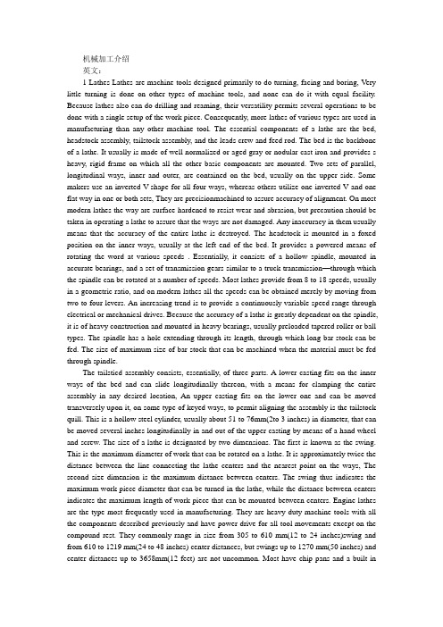
机械加工介绍英文:1 Lathes Lathes are machine tools designed primarily to do turning, facing and boring, V ery little turning is done on other types of machine tools, and none can do it with equal facility. Because lathes also can do drilling and reaming, their versatility permits several operations to be done with a single setup of the work piece. Consequently, more lathes of various types are used in manufacturing than any other machine tool. The essential components of a lathe are the bed, headstock assembly, tailstock assembly, and the leads crew and feed rod. The bed is the backbone of a lathe. It usually is made of well normalized or aged gray or nodular cast iron and provides s heavy, rigid frame on which all the other basic components are mounted. Two sets of parallel, longitudinal ways, inner and outer, are contained on the bed, usually on the upper side. Some makers use an inverted V-shape for all four ways, whereas others utilize one inverted V and one flat way in one or both sets, They are precisionmachined to assure accuracy of alignment. On most modern lathes the way are surface-hardened to resist wear and abrasion, but precaution should be taken in operating a lathe to assure that the ways are not damaged. Any inaccuracy in them usually means that the accuracy of the entire lathe is destroyed. The headstock is mounted in a foxed position on the inner ways, usually at the left end of the bed. It provides a powered means of rotating the word at various speeds . Essentially, it consists of a hollow spindle, mounted in accurate bearings, and a set of transmission gears-similar to a truck transmission—through which the spindle can be rotated at a number of speeds. Most lathes provide from 8 to 18 speeds, usually in a geometric ratio, and on modern lathes all the speeds can be obtained merely by moving from two to four levers. An increasing trend is to provide a continuously variable speed range through electrical or mechanical drives. Because the accuracy of a lathe is greatly dependent on the spindle, it is of heavy construction and mounted in heavy bearings, usually preloaded tapered roller or ball types. The spindle has a hole extending through its length, through which long bar stock can be fed. The size of maximum size of bar stock that can be machined when the material must be fed through spindle.The tailsticd assembly consists, essentially, of three parts. A lower casting fits on the inner ways of the bed and can slide longitudinally thereon, with a means for clamping the entire assembly in any desired location, An upper casting fits on the lower one and can be moved transversely upon it, on some type of keyed ways, to permit aligning the assembly is the tailstock quill. This is a hollow steel cylinder, usually about 51 to 76mm(2to 3 inches) in diameter, that can be moved several inches longitudinally in and out of the upper casting by means of a hand wheel and screw. The size of a lathe is designated by two dimensions. The first is known as the swing. This is the maximum diameter of work that can be rotated on a lathe. It is approximately twice the distance between the line connecting the lathe centers and the nearest point on the ways, The second size dimension is the maximum distance between centers. The swing thus indicates the maximum work piece diameter that can be turned in the lathe, while the distance between centers indicates the maximum length of work piece that can be mounted between centers. Engine lathes are the type most frequently used in manufacturing. They are heavy-duty machine tools with all the components described previously and have power drive for all tool movements except on the compound rest. They commonly range in size from 305 to 610 mm(12 to 24 inches)swing and from 610 to 1219 mm(24 to 48 inches) center distances, but swings up to 1270 mm(50 inches) and center distances up to 3658mm(12 feet) are not uncommon. Most have chip pans and a built-incoolant circulating system. Smaller engine lathes-with swings usually not over 330 mm (13 inches ) –also are available in bench type, designed for the bed to be mounted on a bench on a bench or cabinet. Although engine lathes are versatile and very useful, because of the time required for changing and setting tools and for making measurements on the work piece, thy are not suitable for quantity production. Often the actual chipproduction tine is less than 30% of the total cycle time. In addition, a skilled machinist is required for all the operations, and such persons are costly and often in short supply. However, much of the op erator’s time is consumed by simple, repetitious adjustments and in watching chips being made. Consequently, to reduce or eliminate the amount of skilled labor that is required, turret lathes, screw machines, and other types of semiautomatic and automatic lathes have been highly developed and are widely used in manufacturing. 2 Numerical Control One of the most fundamental concepts in the area of advanced manufacturing technologies is numerical control (NC). Prior to the advent of NC, all machinetools ere manually operated and controlled. Among the many limitations associated with manual control machine tools, perhaps none is more prominent than the limitation of operator skills. With manual control, the quality of the product is directly related to and limited to the skills of the operator. Numerical control represents the first major step away from human control of machine tools. Numerical control means the control of machine tools and other manufacturing systems through the use of prerecorded, written symbolic instructions. Rather than operating a machine tool, an NC technician writes a program that issues operational instructions to the machine tool. For a machine tool to be numerically controlled, it must be interfaced with a device for accepting and decoding the programmed instructions, known as a reader. Numerical control was developed to overcome the limitation of human operators, and it has done so. Numerical control machines are more accurate than manually operated machines, they can produce parts more uniformly, they are faster, and the long-run tooling costs are lower. The development of NC led to the development of several other innovations in manufacturing technology: Electrical discharge machining,Laser cutting,Electron beam welding. Numerical control has also made machine tools more versatile than their manually operated predecessors. An NC machine tool can automatically produce a wide of parts, each involving an assortment of widely varied and complex machining processes. Numerical control has allowed manufacturers to undertake the production of products that would not have been feasible from an economic perspective using manually controlled machine tolls and processes. Like so many advanced technologies, NC was born in the laboratories of the Massachusetts Institute of Technology. The concept of NC was developed in the early 1950s with funding provided by the U.S. Air Force. In its earliest stages, NC machines were able to made straight cuts efficiently and effectively. However, curved paths were a problem because the machine tool had to be programmed to undertake a series of horizontal and vertical steps to produce a curve. The shorter the straight lines making up the steps, the smoother is the curve, Each line segment in the steps had to be calculated. This problem led to the development in 1959 of the Automatically Programmed Tools (APT) language. This is a special programming language for NC that uses statements similar to English language to define the part geometry, describe the cutting tool configuration, and specify the necessary motions. Thedevelopment of the APT language was a major step forward in the fur ther development from those used today. The machines had hardwired logic circuits. The instructional programs were written on punched paper, which was later to be replaced by magnetic plastic tape. A tape readerwas used to interpret the instructions written on the tape for the machine. Together, all of this represented a giant step forward in the control of machine tools. However, there were a number of problems with NC at this point in its development. A major problem was the fragility of the punched paper tape medium. It was common for the paper tape containing the programmed instructions to break or tear during a machining process. This problem was exacerbated by the fact that each successive time a part was produced on a machine tool, the paper tape carrying the programmed instructions had to be rerun through the reader. If it was necessary to produce 100 copies of a given part, it was also necessary to run the paper tape through the reader 100 separate tines. Fragile paper tapes simply could not withstand the rigors of a shop floor environment and this kind of repeated use. This led to the development of a special magnetic plastic tape. Where as the paper carried the programmed instructions as a series of holes punched in the tape, the plastic tape carried the instructions as a series of magnetic dots. The plastic tape was much stronger than the paper tape, which solved the problem of frequent tearing and breakage. However, it still left two other problems. The most important of these was that it was difficult or impossible to change the instructions entered on the tape. To made even the most minor adjustments in a program of instructions, it was necessary to interrupt machining operations and make a new tape. It was also still necessary to run the tape through the reader as many times as there were parts to be produced. Fortunately, computer technology became a reality and soon solved the problems of NC associated with punched paper and plastic tape. The development of a concept known as direct numerical control (DNC) solved the paper and plastic tape problems associated with numerical control by simply eliminating tape as the medium for carrying the programmed instructions. In direct numerical control, machine tools are tied, via a data transmission link, to a host computer. Programs for operating the machine tools are stored in the host computer and fed to the machine tool an needed via the data transmission linkage. Direct numerical control represented a major step forward over punched tape and plastic tape. However, it is subject to the same limitations as all technologies that depend on a host computer. When the host computer goes down, the machine tools also experience downtime. This problem led to the development of computer numerical control.中文翻译:1.车床车床主要是为了进行车外圆、车端面和镗孔等项工作而设计的机床。
外文参考资料及译文
毕业设计(论文)外文参考资料及译文译文题目: development and application of combinedmachine tool组合机床的发展与应用学生姓名:王斑学号: 1021108014专业: M10机械设计制造及其自动化所在学院:机电工程学院指导教师:赵海霞职称:教师2014年 2 月 25 日Development and application of combined machine tool The aggregate machine-tool is take the general part as a foundation, matches by presses the work piece specific shape and the processing technological design special-purpose part and the jig, the composition semiautomatic or the automatic special purpose machine. The aggregate machine-tool selects the method which generally multiple spindle, the multi-knives, the multi-working procedures, many or the multi-locations simultaneously process, production efficiency ratio general engine bed high several times to several dozens times. Because the general part already the standardization and the seriation, might according to need to dispose nimbly, could reduce the design and the manufacturing cycle. The multi-axle-boxes are aggregate machine-tool's core parts. It selects the common parts, carries on the design according to the special-purpose request, in the aggregate machine-tool design's process, is one of work load big parts. It is acts according to the work piece processing hole quantity which and the position the working procedure chart and the processing schematic drawing determined, the cutting specifications and the main axle type design transmission various main axles movement power unit. Its power from the general power box, installs together with the power box in to feed sliding table, may complete drills, twists and so on working processes. To meet the combination of CNC machine tools of development, it is a component of the NC machine tool NC module. Portfolio machine is modular combination of CNC machine tools brought about by the inevitable result is the combination of CNC machine tools necessary foundation, NC module so greatly enriched the portfolio of generic pieces of machine tools, it will cause combination of General Machine Type of a fundamental change. NC module, according to their coordinates NC (axis) of mainly single coordinates, dual coordinate and coordinate. Its spindle number, single and multi-axis module, there are single and multi-axis composite processing module.NC module development, there are mainly two kinds of ways: First, the existing combination of machine tools should be relatively common items, the NC General of the design. At present there is also domestic NC is developing one-dimensional slider, NC two-dimensional (Cross) Waterloo Taiwan, the NC rotary table, all this is the way the NC is based on the characteristics of the development of NC The unique combination of machine tool parts, such as automatic replacement of multi-axis spindle box, the NCrotary knife, NC for the manipulator, NC for me, such as mechanical hand. The past 10 years, machine tools and automatic line group in the highly efficient, high productivity, flexibility and the use of parallel (synchronous) works develop more reasonable and more savings in the programme has made a lot of progress. In particular the automobile industry, in order to improve the performance of motor vehicles, precision machining of components made a number of new demands, so the machine performance requirements are also higher.In recent years, with numerical control technology, electronics technology, computer technology, such as the development of machine tools combination of mechanical structure and control system has also undergone a tremendous change. With the combination of machine tools of development: 1. NC. A combination of CNC machine tools, not only a complete change from the previous relay circuit composed of a combination of machine tool control system, and the head. Also the mechanical structure and composition of machine parts universal standards has or is undergoing an enormous change。
机电实习报告英文版
Executive Summary:This report details my internship experience at XYZ Corporation, a leading manufacturer of industrial machinery. During my internship, I was exposed to various aspects of mechanical and electrical engineering, including design, production, and quality control. The internship provided me with invaluable hands-on experience, enhancing my technical skills and broadening my understanding of the industry. This report outlines the key activities, challenges, and insights gained during the internship.Introduction:My internship at XYZ Corporation, a renowned manufacturer of industrial machinery, was a significant milestone in my academic and professional journey. The internship was a six-month long program, during which I had the opportunity to work with a diverse team of engineers and professionals. The objective of the internship was to gain practical experience in the field of mechanical and electrical engineering, and to understand the intricacies of the manufacturing process.Company Overview:XYZ Corporation is a global leader in the design, development, and manufacturing of industrial machinery. The company has a state-of-the-art manufacturing facility, equipped with cutting-edge technology and skilled workforce. The company’s prod uct portfolio includes conveyors, crushers, and separators, which are used in various industries such as mining, construction, and agriculture.Internship Activities:1. Design and Drafting:During the first month of my internship, I was trained in the use of AutoCAD, a computer-aided design (CAD) software. I worked on drafting various components of industrial machinery, such as conveyors, gears, and bearings. This helped me understand the importance of accurate design in the manufacturing process.2. Production Process:After mastering the CAD software, I was assigned to the production department. I observed the entire production process, from raw material handling to the final assembly of the machinery. I learned about different manufacturing techniques, such as welding, casting, and CNC machining.3. Quality Control:One of the critical aspects of my internship was to learn about quality control. I was trained in the use of various testing equipment, such as calipers, micrometers, and hardness testers. I also participated in the inspection of the machinery components to ensure that they meet the required quality standards.4. Project Management:I was involved in a project aimed at improving the efficiency of the production line. I worked with the project manager and the team to identify potential bottlenecks and suggest improvements. This project helped me understand the importance of teamwork and effective communication in achieving project objectives.5. Client Interaction:Towards the end of my internship, I was assigned to assist the sales team in client interactions. I learned about the importance of understanding customer requirements and providing tailored solutions. This experience enhanced my communication and negotiation skills.Challenges and Insights:1. Adapting to the Work Environment:Initially, I found it challenging to adapt to the fast-paced work environment at XYZ Corporation. However, with the support of my colleagues and supervisors, I was able to quickly acclimate and excel in my responsibilities.2. Technical Knowledge:The internship exposed me to a wide range of technical knowledge, which helped me understand the complexities of the industry. I realized that continuous learning and staying updated with the latest technological advancements are crucial for success in this field.3. Problem-Solving Skills:During the project management phase, I faced several challenges, which required me to think critically and find innovative solutions. This experience enhanced my problem-solving skills and helped me develop a more practical approach to tackling real-world issues.4. Teamwork and Communication:The internship emphasized the importance of teamwork and effective communication. I learned that a collaborative approach can lead tobetter outcomes and a more productive work environment.Conclusion:My internship at XYZ Corporation was a rewarding experience that provided me with a comprehensive understanding of the mechanical and electrical engineering industry. The hands-on experience, combined with the guidance of experienced professionals, has significantly enhanced my technical and soft skills. I am confident that the knowledge and skills gained during this internship will be invaluable in my future career. I would like to express my gratitude to XYZ Corporation for this opportunity and to all the individuals who have guided and supported me throughout the internship.。
机械类毕业设计外文翻译
本科毕业论文(设计)外文翻译学院:机电工程学院专业:机械工程及自动化姓名:高峰指导教师:李延胜2011年 05 月 10日教育部办公厅Failure Analysis,Dimensional Determination And Analysis,Applications OfCamsINTRODUCTIONIt is absolutely essential that a design engineer know how and why parts fail so that reliable machines that require minimum maintenance can be designed.Sometimes a failure can be serious,such as when a tire blows outon an automobile traveling at high speed.On the other hand,a failure may be no more than a nuisance.An example is the loosening of the radiator hose in an automobile cooling system.The consequence of this latter failure is usually the loss of some radiator coolant,a condition that is readily detected and corrected.The type of load a part absorbs is just as significant as the magnitude.Generally speaking,dynamic loads with direction reversals cause greater difficulty than static loads,and therefore,fatigue strength must be considered.Another concern is whether the material is ductile or brittle.For example,brittle materials are considered to be unacceptable where fatigue is involved.Many people mistakingly interpret the word failure to mean the actual breakage of a part.However,a design engineer must consider a broader understanding of what appreciable deformation occurs.A ductile material,however will deform a large amount prior to rupture.Excessive deformation,without fracture,may cause a machine to fail because the deformed part interferes with a moving second part.Therefore,a part fails(even if it has not physically broken)whenever it no longer fulfills its required function.Sometimes failure may be due to abnormal friction or vibration between two mating parts.Failure also may be due to a phenomenon called creep,which is the plastic flow of a material under load at elevated temperatures.In addition,the actual shape of a part may be responsiblefor failure.For example,stress concentrations due to sudden changes in contour must be taken into account.Evaluation of stress considerations is especially important when there are dynamic loads with direction reversals and the material is not very ductile.In general,the design engineer must consider all possible modes of failure,which include the following.——Stress——Deformation——Wear——Corrosion——Vibration——Environmental damage——Loosening of fastening devicesThe part sizes and shapes selected also must take into account many dimensional factors that produce external load effects,such as geometricdiscontinuities,residual stresses due to forming of desired contours,and the application of interference fit joints.Cams are among the most versatile mechanisms available.A cam is a simple two-member device.The input member is the cam itself,while the output member is called the follower.Through the use of cams,a simple input motion can be modified into almost any conceivable output motion that is desired.Some of the common applications of cams are——Camshaft and distributor shaft of automotive engine——Production machine tools——Automatic record players——Printing machines——Automatic washing machines——Automatic dishwashersThe contour of high-speed cams (cam speed in excess of 1000 rpm) must be determined mathematically.However,the vast majority of cams operate at low speeds(less than 500 rpm) or medium-speed cams can be determinedgraphically using a large-scale layout.In general,the greater the cam speed and output load,the greater must be the precision with which the cam contour is machined.DESIGN PROPERTIES OF MATERIALSThe following design properties of materials are defined as they relate to the tensile test.Figure 2.7Static Strength.The strength of a part is the maximum stress that the part can sustain without losing its ability to perform its required function.Thus the static strength may be considered to be approximately equal to the proportional limit,since no plastic deformation takes place and no damage theoretically is done to the material.Stiffness.Stiffness is the deformation-resisting property of a material.The slope of the modulus line and,hence,the modulus of elasticity are measures of the stiffness of a material.Resilience.Resilience is the property of a material that permits it to absorb energy without permanent deformation.The amount of energy absorbed is represented by the area underneath the stress-strain diagram within theelastic region.Toughness.Resilience and toughness are similar properties.However,toughness is the ability to absorb energy without rupture.Thus toughness is represented by the total area underneath the stress-strain diagram, as depicted in Figure 2.8b.Obviously,the toughness and resilience of brittle materials are very low and are approximately equal.Brittleness. A brittle material is one that ruptures before any appreciable plastic deformation takes place.Brittle materials are generally considered undesirable for machine components because they are unable to yield locally at locations of high stress because of geometric stress raisers such as shoulders,holes,notches,or keyways.Ductility. A ductility material exhibits a large amount of plastic deformation prior to rupture.Ductility is measured by the percent of area and percent elongation of a part loaded to rupture.A 5%elongation at rupture is considered to be the dividing line between ductile and brittle materials.Malleability.M alleability is essentially a measure of the compressive ductility of a material and,as such,is an important characteristic of metals that are to be rolled into sheets.Hardness.The hardness of a material is its ability to resistindentation or scratching.Generally speaking,the harder a material,the more brittle it is and,hence,the less resilient.Also,the ultimate strength of a material is roughly proportional to its hardness.Machinability.Machinability is a measure of the relative ease with which a material can be machined.In general,the harder the material,the more difficult it is to machine.Figure 2.8COMPRESSION AND SHEAR STATIC STRENGTHIn addition to the tensile tests,there are other types of static load testing that provide valuable information.Compression Testing.M ost ductile materials have approximately the same properties in compression as in tension.The ultimate strength,however,can not be evaluated for compression.As a ductile specimen flows plastically in compression,the material bulges out,but there is no physical rupture as is the case in tension.Therefore,a ductile material fails in compression as a result of deformation,not stress.Shear Testing.Shafts,bolts,rivets,and welds are located in such a way that shear stresses are produced.A plot of the tensile test.The ultimateshearing strength is defined as the stress at which failure occurs.The ultimate strength in shear,however,does not equal the ultimate strength in tension.For example,in the case of steel,the ultimate shear strength is approximately 75% of the ultimate strength in tension.This difference must be taken into account when shear stresses are encountered in machine components.DYNAMIC LOADSAn applied force that does not vary in any manner is called a static or steady load.It is also common practice to consider applied forces that seldom vary to be static loads.The force that is gradually applied during a tensile test is therefore a static load.On the other hand,forces that vary frequently in magnitude and direction are called dynamic loads.Dynamic loads can be subdivided to the following three categories.Varying Load.W ith varying loads,the magnitude changes,but the direction does not.For example,the load may produce high and low tensile stresses but no compressive stresses.Reversing Load.In this case,both the magnitude and direction change.These load reversals produce alternately varying tensile andcompressive stresses that are commonly referred to as stress reversals.Shock Load.This type of load is due to impact.One example is an elevator dropping on a nest of springs at the bottom of a chute.The resulting maximum spring force can be many times greater than the weight of the elevator,The same type of shock load occurs in automobile springs when a tire hits a bump or hole in the road.FATIGUE FAILURE-THE ENDURANCE LIMIT DIAGRAMThe test specimen in Figure 2.10a.,after a given number of stress reversals will experience a crack at the outer surface where the stress is greatest.The initial crack starts where the stress exceeds the strength of the grain on which it acts.This is usually where there is a small surface defect,such as a material flaw or a tiny scratch.As the number of cycles increases,the initial crack begins to propagate into a continuous series of cracks all around the periphery of the shaft.The conception of the initial crack is itself a stress concentration that accelerates the crack propagation phenomenon.Once the entire periphery becomes cracked,the cracks start to move toward the center of the shaft.Finally,when the remaining solid inner area becomes small enough,the stress exceeds the ultimate strength and the shaft suddenly breaks.Inspection of the break reveals a very interesting pattern,as shown in Figure 2.13.The outer annular area is relatively smooth because mating cracked surfaces had rubbed againsteach other.However,the center portion is rough,indicating a sudden rupture similar to that experienced with the fracture of brittle materials.This brings out an interesting fact.When actual machine parts fail as a result of static loads,they normally deform appreciably because of the ductility of the material.Figure 2.13Thus many static failures can be avoided by making frequent visual observations and replacing all deformed parts.However,fatigue failures give to warning.Fatigue fail mated that over 90% of broken automobile parts have failed through fatigue.The fatigue strength of a material is its ability to resist the propagation of cracks under stress reversals.Endurance limit is a parameter used to measure the fatigue strength of a material.By definition,the endurance limit is the stress value below which an infinite number of cycles will not cause failure.Let us return our attention to the fatigue testing machine in Figure 2.9.The test is run as follows:A small weight is inserted and the motor is turned on.At failure of the test specimen,the counter registers the number of cycles N,and the corresponding maximum bending stress iscalculated from Equation 2.5.The broken specimen is then replaced by an identical one,and an additional weight is inserted to increase the load.A new value of stress is calculated,and the procedure is repeated until failure requires only one complete cycle.A plot is then made of stress versus number of cycles to failure.Figure 2.14a shows the plot,which is called the endurance limit or S-N curve.Since it would take forever to achieve an infinite number of cycles,1 million cycles is used as a reference.Hence the endurance limit can be found from Figure 2.14a by noting that it is the stress level below which the material can sustain 1 million cycles without failure.The relationship depicted in Figure 2.14 is typical for steel,because the curve becomes horizontal as N approaches a very large number.Thus the endurance limit equals the stress level where the curve approaches a horizontal tangent.Owing to the large number of cycles involved,N is usually plotted on a logarithmic scale,as shown in Figure 2.14b.When this is done,the endurance limit value can be readily detected by the horizontal straight line.For steel,the endurance limit equals approximately 50% of the ultimate strength.However,if the surface finish is not of polished equality,the value of the endurance limit will be lower.For example,for steel parts with a machined surface finish of 63 micr oinches ( μin.),the percentage drops to about 40%.For rough surfaces (300μin.or greater),the percentage may be as low as 25%.The most common type of fatigue is that due to bending.The next most frequent is torsion failure,whereas fatigue due to axial loads occurs very seldom.Spring materials are usually tested by applying variable shear stresses that alternate from zero to a maximum value,simulating the actual stress patterns.In the case of some nonferrous metals,the fatigue curve does not level off as the number of cycles becomes very large.This continuing toward zero stress means that a large number of stress reversals will cause failure regardless of how small the value of stress is.Such a material is said to have no endurance limit.For most nonferrous metals having an endurance limit,the value is about 25% of the ultimate strength.EFFECTS OF TEMPERATURE ON YIELD STRENGTH AND MODULUS OF ELASTICITYGenerally speaking,when stating that a material possesses specified values of properties such as modulus of elasticity and yield strength,it is implied that these values exist at room temperature.At low or elevated temperatures,the properties of materials may be drastically different.For example,many metals are more brittle at low temperatures.In addition,the modulus of elasticity and yield strength deteriorate as the temperature increases.Figure 2.23 shows that the yield strength for mild steel is reduced by about 70% in going from room temperature to 1000o F.Figure 2.24 shows the reduction in the modulus of elasticity E for mild steel as the temperature increases.As can be seen from the graph,a 30% reduction in modulus of elasticity occurs in going from room temperature to 1000o F.In this figure,we also can see that a part loaded below the proportional limit at room temperature can be permanently deformed under the same load at elevated temperatures.Figure 2.24CREEP: A PLASTIC PHENOMENONTemperature effects bring us to a phenomenon called creep,which is the increasing plastic deformation of a part under constant load as a function of time.Creep also occurs at room temperature,but the process is so slow that it rarely becomes significant during the expected life of the temperature is raised to 300o C or more,the increasing plastic deformation can become significant within a relatively short period of time.The creep strength of a material is its ability to resist creep,and creep strength data can be obtained by conducting long-time creep tests simulating actual part operating conditions.During the test,the plastic strain is monitored for given material at specified temperatures.Since creep is a plastic deformation phenomenon,the dimensions of a part experiencing creep are permanently altered.Thus,if a part operateswith tight clearances,the design engineer must accurately predict the amount of creep that will occur during the life of the machine.Otherwise,problems such binding or interference can occur.Creep also can be a problem in the case where bolts are used to clamp tow parts together at elevated temperatures.The bolts,under tension,will creep as a function of time.Since the deformation is plastic,loss of clamping force will result in an undesirable loosening of the bolted joint.The extent of this particular phenomenon,called relaxation,can be determined by running appropriate creep strength tests.Figure 2.25 shows typical creep curves for three samples of a mild steel part under a constant tensile load.Notice that for the high-temperature case the creep tends to accelerate until the part fails.The time line in the graph (the x-axis) may represent a period of 10 years,the anticipated life of the product.Figure 2.25SUMMARYThe machine designer must understand the purpose of the static tensile strength test.This test determines a number of mechanical properties of metals that are used in design equations.Such terms as modulus ofelasticity,proportional limit,yield strength,ultimate strength,resilience,and ductility define properties that can be determined from the tensile test.Dynamic loads are those which vary in magnitude and direction and may require an investigation of the machine part’s resistance to failure.Stress reversals may require that the allowable design stress be based on the endurance limit of the material rather than on the yield strength or ultimate strength.Stress concentration occurs at locations where a machine part changes size,such as a hole in a flat plate or a sudden change in width of a flat plate or a groove or fillet on a circular shaft.Note that for the case of a hole in a flat or bar,the value of the maximum stress becomes much larger in relation to the average stress as the size of the hole decreases.Methods of reducing the effect of stress concentration usually involve making the shape change more gradual.Machine parts are designed to operate at some allowable stress below the yield strength or ultimate strength.This approach is used to take care of such unknown factors as material property variations and residual stresses produced during manufacture and the fact that the equations used may be approximate rather that exact.The factor of safety is applied to the yield strength or the ultimate strength to determine the allowablestress.Temperature can affect the mechanical properties of metals.Increases in temperature may cause a metal to expand and creep and may reduce its yield strength and its modulus of elasticity.If most metals are not allowed to expand or contract with a change in temperature,then stresses are set up that may be added to the stresses from the load.This phenomenon is useful in assembling parts by means of interference fits.A hub or ring has an inside diameter slightly smaller than the mating shaft or post.The hub is then heated so that it expands enough to slip over the shaft.When it cools,it exerts a pressure on the shaft resulting in a strong frictional force that prevents loosening.TYPES OF CAM CONFIGURATIONSPlate Cams.This type of cam is the most popular type because it is easy to design and manufacture.Figure 6.1 shows a plate cam.Notice that the follower moves perpendicular to the axis of rotation of the camshaft.All cams operate on the principle that no two objects can occupy the same space at the same time.Thus,as the cam rotates ( in this case,counterclockwise ),the follower must either move upward or bind inside the guide.We will focus our attention on the prevention of binding and attainment of the desired output follower motion.The spring is required to maintain contact between the roller of the follower and the cam contour when the follower is movingdownward.The roller is used to reduce friction and hence wear at the contact surface.For each revolution of the cam,the follower moves through two strokes-bottom dead center to top dead center (BDC to TDC) and TDC to BDC.Figure 6.2 illustrates a plate cam with a pointed follower.Complex motions can be produced with this type of follower because the point can follow precisely any sudden changes in cam contour.However,this design is limited to applications in which the loads are very light;otherwise the contact point of both members will wear prematurely,with subsequent failure.Two additional variations of the plate cam are the pivoted follower and the offset sliding follower,which are illustrated in Figure 6.3.A pivoted follower is used when rotary output motion is desired.Referring to the offset follower,note that the amount of offset used depends on such parameters as pressure angle and cam profile flatness,which will be covered later.A follower that has no offset is called an in-line follower.Figure 6..3Translation Cams.Figure 6.4 depicts a translation cam.The follower slides up and down as the cam translates motion in the horizontal direction.Note that a pivoted follower can be used as well as a sliding-type follower.This type of action is used in certain production machines in which the pattern of the product is used as the cam.A variation on this design would be a three-dimensional cam that rotates as well as translates.For example,a hand-constructed rifle stock is placed in a special lathe.This stock is the pattern,and it performs the function of a cam.As it rotates and translates,the follower controls a tool bit that machines the production stock from a block of wood.Figure 6.4Positive-Motion Cams.In the foregoing cam designs,the contact between the cam and the follower is ensured by the action of the spring forces during the return stroke.However,in high-speed cams,the spring force required to maintain contact may become excessive when added to the dynamic forces generated as a result of accelerations.This situation can result in unacceptably large stress at the contact surface,which in turn can result in premature wear.Positive-motion cams require no spring because the follower is forced to contact the cam in two directions.There are four basic types of positive-motion cams: the cylindrical cam,the grooved-plate cam ( also called a face cam ) ,the matched-plate cam,and the scotch yoke cam.Cylindrical Cam.The cylindrical cam shown in Figure 6.5 produces reciprocating follower motion,whereas the one shown in Figure 6.6 illustrates the application of a pivoted follower.The cam groove can be designed such that several camshaft revolutions are required to produce one complete follower cycle.Grooved-plate Cam.In Figure 6.8 we see a matched-plate cam with a pivoted follower,although the design also can be used with a translation follower.Cams E and F rotate together about the camshaft B.Cam E is always in contact with roller C,while cam F maintains contact with roller D.Rollers C and D are mounted on a bell-crank lever,which is the follower oscillating about point A.Cam E is designed to provide the desired motion of roller C,while cam F provides the desired motion of roller D.Scotch Yoke Cam.This type of cam,which is depicted in Figure 6.9,consists of a circular cam mounted eccentrically on its camshaft.The stroke of the follower equals two times the eccentricity e of the cam.This cam produces simple harmonic motion with no dwell times.Refer to Section 6.8 for further discussion.CAM TERMINOLOGYBefore we become involved with the design of cams,it is desirable to know the various terms used to identify important cam design parameters.Thefollowing terms refer to Figure 6.11.The descriptions will be more understandable if you visualize the cam as stationary and the follower as moving around the cam.Trace Point.The end point of a knife-edge follower or the center of the roller of a roller-type follower.Cam Contour.The actual shape of the cam.Base Circle.The smallest circle that can be drawn tangent to the cam contour.Its center is also the center of the camshaft.The smallest radial size of the cam stars at the base circle.Pitch Curve.The path of the trace point,assuming the cam is stationary and the follower rotates about the cam.Prime Circle.The smallest circle that can be drawn tangent to the pitch curve.Its center is also the center of the camshaft.Pressure Angle.The angle between the direction of motion of the follower and the normal to the pitch curve at the point where the center of the roller lies.Cam Profile.Same as cam contour.BDC.Bottom Dead Center,the position of the follower at its closest point to the cam hub.Stroke.The displacement of the follower in its travel between BDC and TDC.Rise.The displacement of the follower as it travels from BDC to TDC.Return.The displacement of the follower as it travels from TDC or BDC.Ewell.The action of the follower when it remains at a constant distance from the cam hub while the cam turns.A clearer understanding of the significance of the pressure angle canbe gained by referring to Figure 6.12.Here FTis the total force acting on the roller.It must be normal to the surfaces at the contact point.Its direction is obviously not parallel to the direction of motion of the follower.Instead,it is indicated by the angle α,the pressure angle,measured from the line representing the direction of motion of thefollower.Therefore,the force FT has a horizontal component FHand a verticalcomponent FV.The vertical component is the one that drives the followerupward and,therefore,neglecting guide friction,equals the follower Fload.The horizontal component has no useful purpose but it is unavoidable.In fact,it attempts to bend the follower about its guide.This can damage the follower or cause it to bind inside its guide.Obviously,we want the pressure angleto be as possible to minimize the side thrust F.A practical rule of thumbHis to design the cam contour so that the pressure angle does not exceed 30o.The pressure angle,in general,depends on the following four parameters: ——Size of base circle——Amount of offset of follower——Size of roller——Flatness of cam contour ( which depends on follower stroke and type of follower motion used )Some of the preceding parameters cannot be changed without altering the cam requirements,such as space limitations.After we have learned how to design a cam,we will discuss the various methods available to reduce the pressure angle.故障的分析、尺寸的决定以及凸轮的分析和应用前言介绍:作为一名设计工程师有必要知道零件如何发生和为什么会发生故障,以便通过进行最低限度的维修以保证机器的可靠性。
机械加工外文翻译
Introduction of MachiningHave a shape as a processing method, all machining process for the production of the most commonly used and most important method. Machining process is a process generated shape, in this process, Drivers device on the work piece material to be in the form of chip removal. Although in some occasions, the workpiece under no circumstances, the use of mobile equipment to the processing, However, the majority of the machining is not only supporting the workpiece also supporting tools and equipment to complete.Machining know the process has two aspects. Small group of low-cost production. For casting, forging and machining pressure, every production of a specific shape of the workpiece, even a spare parts, almost have to spend the high cost of processing. Welding to rely on the shape of the structure, to a large extent, depend on effective in the form of raw materials. In general, through the use of expensive equipment and without special processing conditions, can be almost any type of raw materials, mechanical processing to convert the raw materials processed into the arbitrary shape of the structure, as long as the external dimensions large enough, it is possible. Because of a production of spare parts, even when the parts and structure of the production batch sizes are suitable for the original casting, Forging or pressure processing to produce, but usually prefer machining.Strict precision and good surface finish, machining the second purpose is the establishment of the high precision and surface finish possible on the basis of. Many parts, if any other means of production belonging to the large-scale production, Well Machining is a low-tolerance and can meet the requirements of small batch production. Besides, many parts on the production and processing of coarse process to improve its general shape of the surface. It is only necessary precision and choose only the surface machining. For instance, thread, in addition to mechanical processing, almost no other processing method for processing. Another example is the blacksmith pieces keyhole processing, as well as training to be conducted immediately after the mechanical completion of the processing.Primary Cutting ParametersCutting the work piece and tool based on the basic relationship between the following four elements to fully describe : the tool geometry, cutting speed, feed rate, depth and penetration of a cutting tool.Cutting Tools must be of a suitable material to manufacture, it must be strong, tough, hard and wear-resistant. Tool geometry -- to the tip plane and cutter angle characteristics -- for each cutting process mustbe correct.Cutting speed is the cutting edge of work piece surface rate, it is inches per minute to show. In order to effectively processing, and cutting speed must adapt to the level of specific parts -- with knives. Generally, the more hard work piece material, the lower the rate.Progressive Tool to speed is cut into the work piece speed. If the work piece or tool for rotating movement, feed rate per round over the number of inches to the measurement. When the work piece or tool for reciprocating movement and feed rate on each trip through the measurement of inches. Generally, in other conditions, feed rate and cutting speed is inversely proportional to.Depth of penetration of a cutting tool -- to inches dollars -- is the tool to the work piece distance. Rotary cutting it to the chip or equal to the width of the linear cutting chip thickness. Rough than finishing, deeper penetration of a cutting tool depth.Rough machining and finishing machiningThere are two kinds of cuts in machine- shop work called, respectively, the "roughing cut" and the "finishing cut". When a piece is "roughed out", it is quite near the shape and size required, but enough metal has been left on the surface to finish smooth and to exact size." Generally speaking, bars of steel, forging, castings, etc. are machined to the required shape and size with only one roughing and one finishing cut. Sometimes, however, certain portions of a piece may require more than one roughing cut. Also, in some jobs, for example, when great accuracy is not needed, or when a comparatively small amount of metal must be removed, a finishing cut may be all that is required. The roughing cut, to remove the greater part of the excess material, should be reasonably heavy, that is, all the machine, or cutting tool, or work, or all three, will stand. So the machinist’s purpose is to remove the excess stock as fast as he can without leaving, at the same time, a surface too torn and rough, without bending the piece if it is slender, and without spoiling the centers. The finishing cut, to make the work smooth and accurate, is a finer cut. The emphasis here is refinement - very sharp tool, comparatively little metal removed, and a higher degree of accuracy in measurement. Whether roughing or finishing, the machinist must set the machine for the given job. He must consider the size and shape of the work and the kind of material, also the kind of tool used and the nature of the cut to be made, then he proceeds to set the machine for the correct speed and feed and to set the tool to take the depth of cut desired.Automatic Fixture DesignAssembly equipment used in the traditional synchronous fixture put parts of the fixture mobile center, to ensure that components from transmission from the plane or equipment plate placed after removal has been scheduled for position. However, in certain applications, mobilemandatory parts of the center line, it may cause parts or equipment damage. When parts vulnerability and may lead to a small vibration abandoned, or when their location is by machine spindle or specific to die, Tolerance again or when the request is a sophisticated, it would rather let the fixture to adapt to the location of parts, and not the contrary. For these tasks, Elyria, Ohio, the company has developed Zaytran a general non-functional data synchronization West category FLEXIBILITY fixture. Fixture because of the interaction and synchronization devices is independent; the synchronous device can use sophisticated equipment to replace the slip without affecting the fixture force. Fixture specification range from 0.2 inches itinerary, 5 pounds clamping force of the six-inch trip, 400-inch clamping force. The characteristics of modern production are becoming smaller and smaller quantities and product specifications biggest changes. Therefore, in the final stages of production, assembly of production, quantity and product design changes appear to be particularly vulnerable. This situation is forcing many companies to make greater efforts to rationalize the extensive reform and the previously mentioned case of assembly automation. Despite flexible fixture behind the rapid development of flexible transport and handling devices, such as backward in the development of industrial robots, it is still expected to increase the flexibility fixture. In fact the important fixture devices -- the production of the devices to strengthen investment on the fixture so that more flexibility in economic support holders.According to their flexibility and fixture can be divided into: special fixture, the fixture combinations, the standard fixture, high flexible fixture. Flexible fixture on different parts of their high adaptability and the few low-cost replacement for the characteristic.Forms can transform the structure of the flexible fixture can be installed with the change of structure components (such as needle cheek plate, Multi-chip components and flake cheek plate), a non-standard work piece gripper or clamping elements (for example: commencement standard with a clamping fixture and mobile components fixture supporting documents), or with ceramic or hardening of the intermediary substances (such as : Mobile particle bed fixture and heat fixture tight fixture). To production, the parts were secured fixture, the need to generate clamping function, its fixture with a few unrelated to the sexual submissive steps.According to the processing was part of that foundation and working characteristics to determine the work piece fixture in the required position, then need to select some stability flat combination, These constitute a stable plane was fixed in the work piece fixture set position on the clamp-profile structure, all balanced and torque, it has also ensured that the work features close to the work piece. Finally, it must be calculated and adjusted, assembly or disassembly be standard fixturecomponents required for the position, so that the work piece firmly by clamping fixture in China. In accordance with this procedure, the outline fixture structure and equipped with the planning and recording process can be automated control.Structural modeling task is to produce some stable flat combination, Thus, these plane of the work pieces clamping force and will fixture stability. According to usual practice, this task can be human-machine dialogue that is almost completely automated way to completion. A man-machine dialogue that is automated fixture structure modeling to determine the merits can be conducted in an organized and planning fixture design reduce the amount of the design, shortening the study period and better distribution of work conditions. In short, can be successfully achieved significantly improve fixture efficiency and effectiveness.Fully prepared to structure programs and the number of material circumstances, the completion of the first successful assembly can save up to 60% of the time.Therefore fixture process modeling agencies is the purpose of the program has appropriate documents.Lathes。
- 1、下载文档前请自行甄别文档内容的完整性,平台不提供额外的编辑、内容补充、找答案等附加服务。
- 2、"仅部分预览"的文档,不可在线预览部分如存在完整性等问题,可反馈申请退款(可完整预览的文档不适用该条件!)。
- 3、如文档侵犯您的权益,请联系客服反馈,我们会尽快为您处理(人工客服工作时间:9:00-18:30)。
毕业设计(前期材料) 目录 第一部分(实习报告) 第1章 公司简介…………………………………………………………………..…………...1 第2章 经过实习………………………………………………………………………..……...1 第3章 实习总结……………………………………………………………………………….4 第4章 致谢………………………………………………………………………….................5
第二部分(中文翻译) 一 绪言…………………………………………………………………..……………………...6 二 基本机械加工参数……………………………………………………………………….....6 三 切削参数的改变对切削温度的影响……………………………………………………….7 四 刀具磨损…………………………………………………………………………………….8 五 自动夹具设计……………………………………………………………………………….9
第三部分(外文原文) I. Introduction…………………………………………………………………………….....10
II. Primary Cutting Parameters…………………………………………………………..... 10 III. Wears of Cutting Tool........................................................................................................ 11 IV. The Effect of Changes in Cutting Parameters on Cutting Temperatures………….....12 V. Automatic Fixture Design……………………………………………………………….. 13 第1章 公司简介 1.1公司地址 本次实习我来到了铜陵卓成金属粉体新材料科技有限责任公司,该公司坐落于美丽的青铜古都,交通便利的安徽皖南的的铜陵市。公司位于铜陵市经济技术开发区,翠湖三路892号路段北侧。该公司成立于2006年,注册资金250万人民币,法人代表为张玉林,其前身为林宝机械。 1.2公司现状及主营产品 该公司2008年正式更名为铜陵卓成金属粉体新材料科技有限责任公司的,公司现有三个分厂,卓成金属粉体新材料科技有限责任公司铜粉厂、螺栓厂、机械厂、各类职工、技术人员160多人,年销售额2000多万,是一家发展中的中小企业,公司的主营方向为铜粉的加工及销售,依托铜陵丰富的铜矿资源着力打造千吨级铜粉年生产加工线,并已开通铜粉加工1号线、3号线、4号线、此外公司还生产各种类型 的螺栓,机械外罩,其生产的产品主要销往江浙等华东地区,也有部分产品出口到国外地区主要是南美的一些国家。但公司主要是以铜粉的加工销售为主,在已开通的3条铜粉生产线中,1号线,主要为传统的铜粉加工生产线,机械设备比较老旧,生产率低下,所生产的铜粉质量一般,主要适合作铜基粉以及少量的合金粉与扩散粉,3号线为半自动化的plc铜粉生产加工线,引进plc自动控制生产线大大提高了铜粉生产效率及经济效益,显著提高了铜粉成品的质量,为企业带来了更多的收益。4号线为电解硫酸铜生产线,电解生产线生产率高,设备成本低,操作相对简单,可以明显提高效益,是企业实现利润的根本保证。目前公司主要铜粉产品主要有+30-100的铜基粉,-100—+200的铜基粉,等各个目数的铜基粉,还有黄铜粉、扩散铜锡粉、扩散660粉等。此外公司也生产各种型号的螺栓、机械外罩,极力打造铜都形象,立足铜都,辐射安徽,面向全国的经营理念争取做大做强。 1.3公司的规划和前景 公司的口号是“卓之为专,成之为信”,喻意卓成,设有技术部、营销部、资产综合管理部、电子商务部、品质部、检测部等。各部门机构设置合适严谨,员工的操行良好,公司本着做大做强的决心,于所有员工齐心协力,同舟共济,直挂云帆济沧海。在未来5年内的目标是年生产值翻一番,达到4000多万元,争创更多的收益,为铜陵的地方经济发展贡献更多的力量。 1.4公司的薪资待遇 公司在铜陵地区对于人才的培养主要依托铜陵的各大高校,对于我们铜陵学院的毕业学生在实习期的基本工资定为1500元,实行一周六天制上班制度,相对于铜陵的薪资总体水平还算可以,在签订就业合同之后每月在2500左右,对于企业来说是能给我们毕业生毕业之后的最好待遇。
第2章 实习经历 2.1总体实习经历 在卓成的首次实习是在公司的铜粉厂,在铜粉厂有半个月的时间,在此期间我主要了解了1号线的铜粉生产加工工艺和过程及各个环节设备机器的操作方法和运行的流程。后来在铜粉检测部学习和了解铜粉各项物理、化学指标的检测方法和步骤,并辅助车间主任完成车间人员班次的排表,以及对氨气发生装置的设备的检修,排水泵的主轴检修等工作,并对合格成品做了跟踪入库记录,用Excel表格记录了产品的出厂指标和相关技术要求。在铜粉厂实习结束后,我又去了螺栓厂,在螺栓厂生产车间详细了解了操作工人生产螺栓的整个过程,从原料圆棒的下料到成型螺栓产品的出厂,整个加工过程有了大致的直观感受。最后在实习的尾声我去了机械厂,机械厂主要生产各种型号的机械外罩,并进行焊接加工工艺的处理,强调很强的团队配合意识,对从CAD图纸到成型产品的出厂,需要大家齐心协力共同完成,这是一个过程,更是一个整体。 2.2铜粉厂的实习经历 在刚进公司的时候,我被安排到了铜粉厂的生产车间1号线去进行操作员实习,主要熟悉铜粉加工工序及设备的操作,了解1号线的铜粉生产全过程。首先从原材料铜块(铜丝)先要经过中频炉的熔化过程。该中频炉的额定工作电压为2KV,额定电流为18A,中频炉在开启时采用直流发电机顺序启动,启动电流为20A,每天的炉化能力为4吨左右,按8小时制,在中频炉开启时,需要对锡包进行加热处理,保证熔化后的铜水可以顺利流下,一般用工业焦炭对其加热,加热至1350度左右即可。在完成熔化后,经过出口时还需要雾化处理,在雾化过程中,需要用真空抽水泵将其中的水分抽出,风干、雾化、这些环节相对简单,处理时需要注意高温蒸汽对人体的灼伤,作业人员一般需要戴防护面罩,在完成雾化、风干后,就来到铜粉生产中最重要的一个环节了,就是进入还原炉进行冷却还原,还原即是去氧的过程将铜粉中的氧用氢还原成纯净的铜基粉,在进行破碎和筛分。 还原炉分为氨气发生装置,氨气分解装置,及温控区域等,采用高压下的液态氨作为原料发生装置,将氨气分解为氮气和氢气,氮气作为保护气体,氢气作为还原气体,在开启还原炉前,先要开启加热装置,进行炉内升温,待炉内温度达到一定时(260度左右)即开始下料进行还原。 2.3还原炉的操作过程 在还原过程中,先通入氮气,打开氮气进气管道,对炉膛进行氮气吹扫,约半小时后关闭氮气进气管道,对炉内的吹扫工作结束,然后缓慢打开氢气进气管道,将氢气压力至0.2-0.5Mpa并定时检查氢气的压力值确保其恒定在设定的压力区间内,待到新氢气达到18Mpa左右时,点燃导火管口对其进行正式的还原工作,还原时氨气进气阀控制在0.5Mpa内,中央温度控制区有5个温度控制区域分为上下两个半区,温度分别设定在:1区450度、2区450度、3区450度、4区375度、5区480度,在达到各自温控时,绿色指示会闪跳,表示设定温度内正常运行。 2.4下料速度的控制及破碎和筛分合批过程 在还原过程中需要注意下料的速度,一般控制在一分钟内五个铲锹的量,保证下料的匀速和连续性,并接通排水蒸汽导管,将还原后的水蒸气及时排出,以免影响还原质量。在经过还原之后铜粉块就成了纯净的无氧无杂质的铜基粉块了,之后对其进行的是破碎处理,在破碎环节需开启古风机,破碎机,在破碎时同样要注意下料的速度,不宜太快,否则容易烧坏电动机导致生产中断。在破碎之后还需要进行筛分处理,将破碎后的铜基粉倒入筛分机筛分出不同目数的铜基粉,在筛分之后按厂家提供的发货要求对筛分后的铜粉进行合批处理,知道合批后的检测数据达到厂家出厂的发货要求为止。整个铜粉的生产过程大致如此,在进行完所有的熔化、雾化、还原、破碎、筛分、合批、之后基本完成其整个生产过程。 2.5螺栓厂的实习经历 在半个月的铜粉厂实习之后我来到了螺栓厂,主要了解螺栓的生产工艺和过程,在实际的生产中,对于螺栓的材料的收缩和伸长率会对最终成形产品的尺寸有一些影响有了切实感受。在计算下料的长度时,需要充分考虑到材料的机械可加工性能,并能及时发现加工过程中存在的问题。在螺栓生产中,螺栓主要是连接紧固件,通用化,标准化,需要考虑到产品良好的互换性,保证加工零件的可互换性和连接的可靠性。在产品生产过程中,工序较多,而且繁杂,对尺寸精度要求非常高,在生产中需要认真集中精力,全力做好每一道工序,保证产品的质量,创造更好的经济效益。 2.6在机械厂的实习经历 在实习的尾声,去了卓成金属粉体新材料科技有限责任公司的机械厂,这是本次实习的最后一站,在这里我主要了解了机械外罩的生产过程,在产品的制造过程中,需要不停的进行切割,不停的焊接,热工艺处理及漆料的喷涂,风干、贴标签,每个看似简单的环节都有我们工人的艰辛和汗水,是大家的共同努力才创造出的产品,在这里我不仅学到了加工工艺,更懂得了团队协作的重要性,在一个相互关联的整体我们必须齐心协力才能创造更多更好的效益。 第3章 实习小结 一个月的实习看似短暂却又不那么简单,时间虽然短,但却使我收获非常多,人生的第一份工作,第一次的工作经历,第一次面对老师学生这种单纯师生关系以外的关系,这种经历,这种感觉真的只有当你走过风景时才能体会得到,以后的人生路也许很长,所面对的工作也会相对稳定并一成不变,但这一个月,却是我人生积淀的开始,从新开始,从新出发,我们需要感谢更需要铭记,有些逝去的风景和旅途在下一站的航程里也许不会再见,所以相遇就当怀念。