韩国CoreRiver电容IC-2
NCP1207A中文资料

5.0 ms Timeout
Timeout Reset
380 ns
L.E.B.
CS
Demag
ÁÁÁÁÁÁMAÁÁÁXIMÁÁÁUMÁÁÁRATÁÁÁINGÁÁÁS ÁÁÁÁÁÁÁÁÁÁÁÁÁÁÁFRiÁÁÁgautirnÁÁÁeg2.ÁÁÁInteÁÁÁrnaÁÁÁl CiÁÁÁrcuiÁÁÁt ArÁÁÁchitÁÁÁectÁÁÁureÁÁÁÁÁÁÁÁÁÁÁÁSymÁÁÁbolÁÁÁÁÁÁVaÁÁlÁue ÁÁÁÁÁÁUniÁÁtÁs
© Semiconductor Components Industries, LLC, 2004
1
November, 2004 − Rev. 1
Publication Order Number: NCP1207A/D
元器件交易网
NCP1207A
Universal Network
NCP1207ADR2 SOIC−8 2500/Tape & Reel
NCP1207ADR2G NCP1207AP
SOIC−8 (Pb−Free)
PDIP−8
2500/Tape & Reel 50 Units/Tube
†For information on tape and reel specifications, including part orientation and tape sizes, please refer to our Tape and Reel Packaging Specifications Brochure, BRD8011/D.
2
FB
Sets the peak current setpoint By connecting an Optocoupler to this pin, the peak current setpoint is
24lc256系列中文
1.8-5.5V 400 kHz (2) 2.5-5.5V 400 kHz 1.8-5.5V 400 kHz(2) 2.5-5.5V 400 kHz 4.5V-5.5V 400 kHz
8 字节
16 字节 16 字节
整个阵列
整个阵列 无
无
A0, A1, A2 A0, A1, A2
I I, E
I I C, I, E
装。
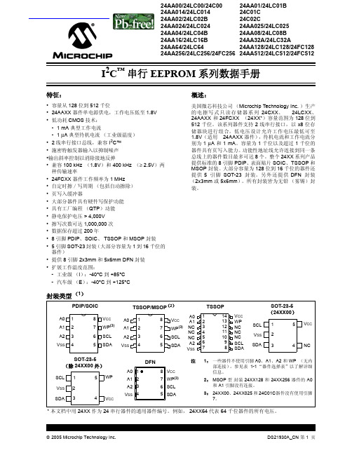
封装类型 (1)
PDIP/SOIC
TSSOP/MSOP(2)
A0 1 A1 2 A2 3 VSS 4
8 VCC
A0 1
7 WP(3) A1 2
6 SCL
A2 3
5 SDA VSS 4
8 VCC
A0 A1
7 WP(3) NC NC
6 SCL NC
5
SDA
A2 VSS
TSSOP
1
14
2
13
3
12
4
11
1.8-5.5V 2.5-5.5V 1.8-5.5V
400 kHz (2)
400 kHz 1 MHz(3)
64 字节
整个阵列
A0, A1, A2(4)
I
P, SN, SM, ST, MS, MF,
I, E ST14
I
256 千位器件
24AA256
1.8-5.5V 400 kHz (2)
24LC256 24FC256
2005 Microchip Technology Inc.
DS21930A_CN 第 3 页
24AAXX/24LCXX/24FCXX
2.0 电气特性
绝对最大额定值 (†)
VCC.............................................................................................................................................................................6.5V 相对于 Vss 的所有输入和输出 ............................................................................................................ -0.6V 到 VCC +1.0V 存储温度 ................................................................................................................................................. -65°C 到 +150°C 环境温度 (使用电源时)........................................................................................................................ -40°C 到 +125°C 所有引脚静电保护 ....................................................................................................................................................................≥ 4 kV
MAX2870中文规格书

PARAMETER
CONDITIONS
REFERENCE OSCILLATOR INPUT (REF_IN)
REF_IN Input Frequency Range
REF_IN Input Sensitivity
REF_IN Input Capacitance
REF_IN Input Current
CONDITIONS
CP[3:0] = 1111, RSET = 5.1kI CP[3:0] = 0000, RSET = 5.1kI
With output dividers (1/2/4/8/16/32/64/128)
Open loop Open loop into 2:1 VSWR Fundamental VCO output Fundamental VCO output VCO output divided-by-2 VCO output divided-by-2
定购信息在数据资料的最后给出。 典型应用电路在数据手资料的最后给出。
相关型号以及配合该器件使用的推荐产品,请参见:china.maximintegrated. com/MAX2870.related。
功能框图
MAX2870
REF_IN
CLK DATA
LE
MUX
R COUNTER
X2
SPI AND REGISTERS
Both channels enabled, maximum output power
Total, including RFOUT, both channel (Note 3)
Each output divide-by-2 ICCVCO + ICCRF (Note 3) Low-power sleep mode
英飞凌低压MOS选型
Product Type BSB012NE2LX BSB014N04LX3 G BSB015N04NX3 G BSB017N03LX3 G BSB012N03LX3 G BSB028N06NN3 G BSB044N08NN3 G BSB056N10NN3 G BSB013NE2LXI BSB008NE2LX BSB150N15NZ3 G BSB280N15NZ3 G BSF024N03LT3 G BSF050N03LQ3 G BSF077N06NT3 G BSF030NE2LQ BSF134N10NJ3 G IPB067N08N3 G IPB023N04N G IPB034N03L G IPB015N04L G IPB027N10N3 G IPB035N08N3 G IPB015N04N G IPB019N06L3 G IPB083N10N3 G IPB042N10N3 G IPB054N06N3 G IPB034N06L3 G IPB039N04L G IPB037N06N3 G IPB041N04N G IPB048N06L G IPB050N06N G IPB097N08N3 G IPB052N04N G IPB055N03L G IPB054N08N3 G IPB042N03L G IPB022N04L G IPB065N03L G IPB072N15N3 G IPB049N06L3 G IPB025N08N3 G IPB080N03L G IPB081N06L3 G IPB075N04L G IPB114N03L G IPB093N04L G IPB147N03L G IPB096N03L G IPB136N08N3 G
IPB200N15N3 G IPB090N06N3 G IPB029N06N3 G IPB021N06N3 G IPB230N06L3 G IPB260N06N3 G IPB049NE7N3 G IPB031NE7N3 G IPB020NE7N3 G IPB123N10N3 G IPB038N12N3 G IPB144N12N3 G IPB320N20N3 G IPB107N20N3 G IPB200N25N3 G IPB600N25N3 G BUZ32 H3045A BUZ31 H3045A IPB108N15N3 G BUZ30A H3045A IPB065N15N3 G IPB530N15N3 G SPB100N03S2-03 G IPB009N03L G IPB011N04L G IPB011N04N G IPB016N06L3 G IPB017N06N3 G IPB019N08N3 G IPB020N04N G IPB023N06N3 G IPB025N10N3 G IPB030N08N3 G IPB039N10N3 G IPB036N12N3 G IPB034N06N3 G SPD07N20 G IPD031N06L3 G IPD034N06N3 G IPD035N06L3 G IPD036N04L G IPD038N06N3 G IPD038N04N G IPD048N06L3 G IPD053N06N3 G IPD053N08N3 G SPD50N03S2L-06 G SPD30N03S2L-07 G IPD068N10N3 G SPD50N03S2-07 G IPD079N06L3 G IPD082N10N3 G IPD088N04L G IPD088N06N3 G IPD096N08N3 G SPD30N03S2L-10 G
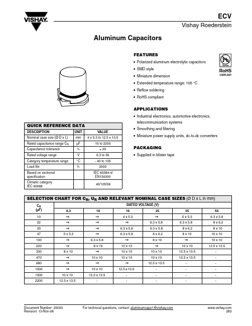
ECV中文资料
Document Number: 25003For technical questions, contact: aluminumcaps1@Aluminum CapacitorsECVVishay RoedersteinFEATURES•Polarized aluminum electrolytic capacitors •SMD style•Miniature dimension•Extended temperature range: 105 °C •Reflow soldering •RoHS compliantAPPLICATIONS•Industrial electronics, automotive electronics, telecommunication systems•Smoothing and filtering•Miniature power supply units, dc-to-dc convertersPACKAGING•Supplied in blister tapeQUICK REFERENCE DATADESCRIPTIONUNIT VALUENominal case size (Ø D x L)mm 4 x 5.3 to 12.5 x 13.5Rated capacitance range C R µF 10 to 2200 Capacitance tolerance %± 20Rated voltage range V 6.3 to 50 Category temperature range °C - 40 to 105 Load lifeh2000Based on sectional specification IEC 60384-4/EN130300Climatic category IEC 6006840/105/56SELECTION CHART FOR C R , U R AND RELEVANT NOMINAL CASE SIZES (Ø D x L in mm)C R (µF)RATED VOLTAGE (V)6.3101625355010→→ 4 x 5.3→ 5 x 5.3 6.3 x 5.822→→→ 6.3 x 5.8 6.3 x 5.88 x 6.233→→ 6.3 x 5.8 6.3 x 5.8 8 x 6.28 x 1047 5 x 5.3→ 6.3 x 5.88 x 6.2 8 x 1010 x 10100→ 6.3 x 5.8→8 x 10→10 x 10220→8 x 1010 x 10→ 10 x 1012.5 x 13.53308 x 10→10 x 1010 x 10 12.5 x 13.5-470→10 x 1010 x 1010 x 1012.5 x 13.5-680→→→12.5 x 13.5--1000→10 x 1012.5 x 13.5---150010 x 1012.5 x 13.5----220012.5 x 13.5----- For technical questions, contact: aluminumcaps1@Document Number: 25003ECVVishay RoedersteinAluminum CapacitorsNoteUnless otherwise specified, all electrical values apply at T amb =20°C, P = 86 to 106kPa, RH =45to 75 %.ORDERING EXAMPLEECV 220 µF/35 V, ± 20 %, size 10 x 10 mm Ordering code: MALSECV00AG322FARKFor Standard Packaging Quantity (SPQ) and Minimum Order Quantity (MOQ) please refer to our price list or contact customer service.ELECTRICAL DATASYMBOL DESCRIPTIONU R rated voltageC R rated capacitance at 120 Hztan δmax. dissipation factor at 120HzR ESR max. equivalent series resistance at 120 Hz I Rrated alternating current at 120 Hz and upper catagory temperatureELECTRICAL DATA AND ORDERING INFORMATIONU R (V)C R 120 Hz (µF)DIMENSIONSD x L (mm)tan δ120 Hz R ESR120 Hz/20 °C(Ω)I R120 Hz/105 °C(mA)WEIGHT (g)CATALOG NUMBER 6.347 5 x 5.30.22 6.21360.17MALSECV00BC247BARK 3308 x 100.28 1.13288 1.00MALSECV00AF333BARK 150010 x 100.280.25560 1.21MALSECV00AG415BARK 220012.5 x 13.50.280.17730 2.00MALSECV00AH422BARK 10100 6.3 x 5.80.19 2.52600.30MALSECV00AD310CARK 2208 x 100.24 1.45173 1.00MALSECV00AF322CARK 47010 x 100.240.68351 1.21MALSECV00AG347CARK 100010 x 100.240.32550 1.21MALSECV00AG410CARK 150012.5 x 13.50.240.21650 2.00MALSECV00AH415CARK 1610 4 x 5.30.1621.22170.12MALSECV00BB210DARK 33 6.3 x 5.80.16 6.43400.30MALSECV00AD233DARK 47 6.3 x 5.80.16 4.52500.30MALSECV00AD247DARK 22010 x 100.20 1.21330 1.21MALSECV00AG322DARK 33010 x 100.200.80441 1.21MALSECV00AG333DARK 47010 x 100.200.56489 1.21MALSECV00AG347DARK 100012.5 x 13.50.200.276002.00MALSECV00AH410DARKDocument Number: 25003For technical questions, contact: aluminumcaps1@ECVAluminum CapacitorsVishay RoedersteinREFLOW SOLDERING CONDITIONS FOR SMD ALUMINUM ELECTROLYTIC CAPACITORS2522 6.3 x 5.80.148.44380.30MALSECV00AD222EARK 33 6.3 x 5.80.14 5.63480.30MALSECV00AD233EARK 478 x 6.20.16 4.52790.55MALSECV00AE247EARK 1008 x 100.16 2.12181 1.00MALSECV00AF310EARK 33010 x 100.160.64372 1.21MALSECV00AG333EARK 47010 x 100.160.45450 1.21MALSECV00AG347EARK 68012.5 x 13.50.160.31500 2.00MALSECV00AH368EARK 3510 5 x 5.30.1215.92240.17MALSECV00BC210FARK 22 6.3 x 5.80.127.23420.30MALSECV00AD222FARK 338 x 6.20.13 5.22760.55MALSECV00AE233FARK 478 x 100.13 3.67124 1.00MALSECV00AF247FARK 22010 x 100.130.78450 1.21MALSECV00AG322FARK 33012.5 x 13.50.130.52500 2.00MALSECV00AH333FARK 47012.5 x 13.50.130.37600 2.00MALSECV00AH347FARK 5010 6.3 x 5.80.1013.26300.30MALSECV00AD210HARK 228 x 6.20.127.23670.55MALSECV00AE222HARK 338 x 100.12 4.82133 1.00MALSECV00AF233HARK 4710 x 100.12 3.39180 1.21MALSECV00AG247HARK 10010 x 100.12 1.59310 1.21MALSECV00AG310HARK 22012.5 x 13.50.120.724802.00MALSECV00AH322HARKPROFILE FEATURESOLDERING CONDITIONØ 4 ~ Ø 10Ø 12.5Ø 16Average ramp-up rate (T L to T P) 3 °C/s max. 3 °C/s max.PreheatT emperature min. (T s min.)150 °C 150 °C T emperature max. (T s max.)200 °C 200 °CTime (T s min. to T s max.)60 ~ 150 s 40 ~ 120 s40 ~ 100 s T s max. to T L Ramp-up rate3 °C/s max.3 °C/s max.ELECTRICAL DATA AND ORDERING INFORMATIONU R (V)C R 120 Hz (µF)DIMENSIONSD x L (mm)tan δ120 Hz R ESR120 Hz/20 °C(Ω)I R120 Hz/105 °C(mA)WEIGHT (g)CATALOG NUMBER For technical questions, contact: aluminumcaps1@Document Number: 25003ECVVishay RoedersteinAluminum CapacitorsTime maintained above Temperature (T L )217 °C 217 °C Time (t L )60 ~ 90 s 40 ~ 60 sPeak/classification temperature (T P )250 °C 240 °C230 °CTime within 5 °C of actual peak temperature (T P )10 s max.10 s max.Ramp-down rate3 °C/s max. 3 °C/s max.Time 25 °C to peak temperature8 min max.8 min max.RESISTANCE TO SOLDERING HEATLeakage current Less than specified value Capacitance value Within ± 10 % of initial value tan δLess than specified valueLOW TEMPERATURE BEHAVIOR (at 120 Hz)IMPEDANCE RATIO (Z) T2/(Z) T1RATED VOLTAGE (V)T2/T16.31016253550- 25 °C/+ 20 °C 332222- 40 °C/+ 20 °C854333PROFILE FEATUREADDITIONAL ELECTRICAL DATAPARAMETERCONDITIONSVALUECurrentLeakage current(T est conditions: U R , 20 °C)After 2 minutes at U RI L2 ≤ 0.01 x C R x U Ror 3 µAfor U R ≤ 100 V (whichever is greater)ResistanceEquivalent series resistance (ESR)Calculated from tan δmax.ESR = tan δ/2 π f C RMULTIPLIER OF RIPPLE CURRENT (I R ) AS A FUNCTION OF FREQUENCYFREQUENCY (Hz)I R MULTIPLIER FOR U R ≤ 100 V500.70120 1.00300 1.171000 1.36≥ 10 0001.50TEST PROCEDURES AND REQUIREMENTSTEST PROCEDURE (QUICK REFERENCE)REQUIREMENTSLoad lifeT amb = 105 °C U R and I R applied After 2000 hΔC/C: ± 20 % of initial value I L ≤ spec. limittan δ ≤ 2 x spec. limit Shelf lifeNo voltage applied After 1000 hAfter test: U R to be applied for 30 min 24 to 48 h before measurementΔC/C: ± 20 % of initial value I L ≤ spec. limittan δ ≤ 2 x spec. limitDisclaimer Legal Disclaimer NoticeVishayAll product specifications and data are subject to change without notice.Vishay Intertechnology, Inc., its affiliates, agents, and employees, and all persons acting on its or their behalf (collectively, “Vishay”), disclaim any and all liability for any errors, inaccuracies or incompleteness contained herein or in any other disclosure relating to any product.Vishay disclaims any and all liability arising out of the use or application of any product described herein or of any information provided herein to the maximum extent permitted by law. The product specifications do not expand or otherwise modify Vishay’s terms and conditions of purchase, including but not limited to the warranty expressed therein, which apply to these products.No license, express or implied, by estoppel or otherwise, to any intellectual property rights is granted by this document or by any conduct of Vishay.The products shown herein are not designed for use in medical, life-saving, or life-sustaining applications unless otherwise expressly indicated. Customers using or selling Vishay products not expressly indicated for use in such applications do so entirely at their own risk and agree to fully indemnify Vishay for any damages arising or resulting from such use or sale. Please contact authorized Vishay personnel to obtain written terms and conditions regarding products designed for such applications.Product names and markings noted herein may be trademarks of their respective owners.元器件交易网Document Number: 。
STATEC 2011设备说明

0~999.9mV(Step 0.1 mV, Accuracy :ADC 16Bits) 2 Station Multiplexing AC Power:210~250VAC,50/60HZ,1Phase DC Power Supply:,+5V/+12V, ±15V,±24V DM2000A:±24V 2000B:±36V, Voltage control(40V~220V) 440mm(W) * 620 mm(D) * 600mm(H) 50Kg
Wide range VDS/VCB (1 to 200V) High Accuracy Sample & Holed (ADC 16Bits) Easy Operation & Maintenance Quick Set-up Installation Windows XP based Operation IE/ID – DM2000A:20A
Copyright © 2010 STATEC Co.,Ltd.
www.statec.co.kr
Ⅱ. Hardware
1. Discrete test system- DM2000A/B
The DM2000 test system series is used to measure the thermal resistance characteristics of Diodes, transistors, MOSFETs ,IGBTs The thermal resistance characteristics of the MOSFETs, Transistors, etc are measured as the temperature change (㎷) of the PN junction. Consideration of a contact check function and an oscillation detection function to prevent the wrong measurement. DM2000 is designed to have 2-channel multiplexing capability.
CY7C64215-56LFXC资料
3.2 The Digital System
The Digital System is composed of 4 digital enCoRe III blocks. Each block is an 8-bit resource that can be used alone or combined with other blocks to form 8, 16, 24, and 32-bit peripherals, which are called user module references.元器件交易网CY7 Nhomakorabea64215
enCoRe™ III Full Speed USB Controller
1.0 Features
• Powerful Harvard Architecture Processor — M8C Processor Speeds to 24 MHz — Two 8x8 Multiply, 32-bit Accumulate — 3.0 to 5.25V Operating Voltage — USB Temperature Range: 0°C to +70°C
SIM6800M系列应用手册
1 4"/,&/&-&$53*$$0 -5%
7FS
)JHI7PMUBHFQIBTF.PUPS%SJWFS*$ 4*..4FSJFT
"QQMJDBUJPO /PUF
1.产品概要 SIM6800M 系列是将输出功率器件具有各种保护功能的预驱 IC、带有限流电阻的自举二极管封装在一起的逆 变ɾ功率ɾ模块。 适用于风扇、泵、压缩机等高压 相电机逆变应用。 图 1 所示为内部方块图。
7FS
)JHI7PMUBHFQIBTF.PUPS%SJWFS*$ 4*..4FSJFT
"QQMJDBUJPO/PUF
SIM6800M 系列 应用手册
目录 1 . 产 品 概 要 . . . . . . . . . . . . . . . . . . . . . . . . . . . . . . . . . . . . . . . 2 2 . 特 征 . . . . . . . . . . . . . . . . . . . . . . . . . . . . . . . . . . . . . . . . . . 3 3 . 产 品 一 览 . . . . . . . . . . . . . . . . . . . . . . . . . . . . . . . . . . . . . . . 5 4 . 端 子 功 能 . . . . . . . . . . . . . . . . . . . . . . . . . . . . . . . . . . . . . . . 6 5 . 保 护 功 能 . . . . . . . . . . . . . . . . . . . . . . . . . . . . . . . . . . . . . . . 1 1 6 . 应 用 电 路 例 . . . . . . . . . . . . . . . . . . . . . . . . . . . . . . . . . . . . . 1 6 7 . 使 用 上 的 注 意 点 . . . . . . . . . . . . . . . . . . . . . . . . . . . . . . . . . 1 9 8. 特性数据
电磁兼容(EMC)设计参考电路
1000pF/2KV FBMA-11-160808-601A10T
1 2 3.3V-Earth
L5
1000pF
C5
C6
1000pF
C1 1000pF
L3
C4 100nF
C3
100nF
C13 1000pF/2KV C14 1000pF/2KV
A
备注: 1、C2、C9、C10、C11 为预设计,根据实际的情况增加,一般不需要增加; 2、C13、C14为预设计,根据实际的情况增加或调整; 3.如防雷等级需要打空接(4、5、7、8)pin,可接上D5做防护。 4.此方案相比中心抽头的方案有了明显的差摸保护。如果要测试绝缘阻抗,请与工程师确认具体的方案。 5.如果4、5、7、8 PIN 不需要测试的话,这部分的器件可以不加
5
3
2
1
千兆网口EMC设计标准电路
D
C1 100nF
1 TCT1 TD1+ TD1-
U1
MCT1 MX1+ MX124 23 22 MX1+ MX1MX1+ MX1MX2+ MX3+ MX3MX2MX4+ MX41 2 3 4 5 6 7 8 MX1+ MX1MX2+ MX3+ MX3MX2MX4+ MX49
MCT3 MX3+ MX3-
18 17 16 MX3+ MX3-
TVS3
BV03C
330R R5 link_o
C4 100nF
10 11 12
TCT4 TD4+ TD4-
MCT4 MX4+ MX4-
15 14 13 MX4+ MX4-
03_SCALE-2 产品型谱
© 2013 CONCEPT | Power Integrations
9
SCALE-2 Driver Cores
2SC0650P - Ultra-flat and highest power density dual channel driver core - For IGBTs and MOSFETs up to 1700V - ±50A gate current - +15V/-10V IGBT mode, +10…20V/0V MOSFET mode - 6W per channel - Direct paralleling capability - Regulated gate-emitter voltage - Advanced active clamping - Short-circuit protection - Under-voltage lockout - 100kV/us - Up to 150kHz, delay time <80ns, jitter <± 1ns - Safe isolation to EN50178 - UL compliant - -40°C…+85°C
3
SCALE-2 Driver Cores
2SC0108T - Ultra-compact dual channel driver core - For IGBTs 600V to 1700V - ±8A gate current, +15V/-8V - 1W per channel - Direct paralleling capability - Regulated gate-emitter voltage - Short-circuit protection - Under-voltage lockout - Up to 50kHz - Delay time <100ns, jitter <± 4ns - 75kV/us - Safe isolation to EN50178 - UL compliant - Two Types: 2SC0108T2Ax-17 (-20°C…+85°) 2SC0108T2Bx-17 (-40°C…+85°)
- 1、下载文档前请自行甄别文档内容的完整性,平台不提供额外的编辑、内容补充、找答案等附加服务。
- 2、"仅部分预览"的文档,不可在线预览部分如存在完整性等问题,可反馈申请退款(可完整预览的文档不适用该条件!)。
- 3、如文档侵犯您的权益,请联系客服反馈,我们会尽快为您处理(人工客服工作时间:9:00-18:30)。
Touch Screen Control IC
Confidential Document
深圳市天机触摸技术有限公司
1/8
Touch Sensor Control IC
Technical brief document Ver. 1.0
Revision Date
2010. 10.15
Touch Screen Control IC
Confidential Document
深圳市天机触摸技术有限公司
2/8
C O N T E N T S
1. General Description
2. Application
3. Capacitive Touch Sensor Control IC
4. H/W Block Diagram
5. ITO sensor pattern guide
6. I2C Overview
7. Mechanical Structure
8. Customized Design Process
Touch Screen Control IC
Confidential Document
深圳市天机触摸技术有限公司
3/8
1. General Description
此技术资料为电容式触摸屏的设计所需要的技术资料说明。
此资料以电容式触摸屏所用的IC的主要特征及性能、所提供的S/W及技术设计指南构成。
希望贵公司参照此资料,开发出成功的产品。
为了贵公司能成功的完善开发,天机触摸技术有限公司会尽全力为贵公司提供最新技术以做约定。
2. Application
Mobile phone / MP3P / MID / PMP / DSC
3. Capacitive Touch Sensor Control IC
3.1 IC Manufacture : Coreriver semiconductor
3.2 Self sensing IC series general specs
Part NO Core Multi Volt InterfaceScreen Channel Package
TC3.0-24 80c52 Vector Zoom 2.2 ~ 3.6V 2-I2C 1-UART ~4.0 inch24 5 x 5
TC3.0-16 ~3.0 inch21 4 x 4
3.3 Mutual Sensing IC series general specs
Part NO Core Multi Volt InterfaceScreen Channel Package
TC400
DSP Real 2 point
Drawing
2.2 ~
3.6V
2-I2C
2-UART
1-SPI
~6.0 inch34 6 x 6
TC410 ~8.0 inch52 8 x 8
TC460 ~12 inch96 10 x 10
Touch Screen Control IC
Confidential Document
深圳市天机触摸技术有限公司
4/8
4. H/W Block Diagram
4.1 Self Sensing Touch Screen Block Diagram
- 接口 : I2C 6pin 接口 (Vcc, GND, SDA, SCL, INT, Reset
)
- FPCB设计 : 天机触摸技术有限公司(无偿设计)
4.2 Mutual Sensing Touch Screen Block Diagram
- 接口 : I2C 6pin 接口 (Vcc, GND, SDA, SCL, INT, Reset )
- 下载pins : 2 pin (TDO, TDI)
- FPCB设计 : 天机触摸技术有限公司(无偿设计)
Touch Screen Control IC
Confidential Document
深圳市天机触摸技术有限公司
5/8
5. ITO sensor pattern guide
5.1 ITO Film sensor pattern design guide
- 建议模式 : Diamond图案
- 推荐尺寸& C/H : 依照屏幕尺寸
- ITO图案设计 : 天机触摸技术有限公司(无偿设计)
5.2 ITO Glass sensor pattern design guide
- 建议模式 : Diamond图案
- 推荐尺寸& C/H : 依照屏幕尺寸
- ITO 图案设计 : 天机触摸技术有限公司(无偿设计)
Touch Screen Control IC
Confidential Document
深圳市天机触摸技术有限公司
6/8
6. I2C Overview
Touch Screen Control IC
Confidential Document
深圳市天机触摸技术有限公司
7/8
7. Mechanical Structure
7.1 W/F/F
<结构> <厚度>
强化玻璃 0.7㎜, 1.1㎜
OCA 50㎛ , 100㎛
ITO 菲林 125㎛ , 188㎛
OCA 50㎛ , 100㎛
ITO 菲林 125㎛ , 188㎛
LCD 模块 Total : 1.1T ~
7.2 W/G
<结构> <厚度>
强化玻璃 0.7㎜, 1.1㎜
OCA 50㎛
ITO 玻璃 0.55㎜, 0.7㎜
LCD 模块 Total : 1.30T ~
Touch Screen Control IC
Confidential Document
深圳市天机触摸技术有限公司
8/8
8. Customized Design Process
项目步骤 客户 备注
描述 H/W M/E S/W 采购
产品展示 ● ● ● ●
* 检查设计、功能、规格、价格
△ △ △ △
项目开始
咨询的规格
● ● ● ●
* 展示方法、尺寸、场所
△ △
* 模块的尺寸
△ △ △
△
* FPCB 结构
* H/W 的构图
△
*O/S , 接口描述 ,
△ △
* 驱动程序开发
△
* 每个样品时间表
△ △ △ △
咨询 TSP Maker
第一个样品发送&检查 ● ● ●
* 触动敏感度的质量
△ △
* 看M/E的设计
△
咨询 TSP Maker
* 看接口
△
* 解决问题
△ △ △
第二个样品发送& 检查
● ● ● ●
* 修改第一个样品
△ △
* 细节调整
△ △
* 处理通过
△ △ △
采购单 (P/O) ●
P/P & M/P 的发送
●
4周左右