Calculation of Stresses and Slips in Helical Layers of Dynamically Bent Flexible Pipes
土木工程英文论文 专业英语词汇
dial gauge 百分表1/1000 mm LVDTs 千分表Demec gauge 缝隙测量计joist 工字钢梁superposition 叠加原理creep function/compliance 徐变函数creep coefficient 徐变系数aging coefficient 老化系数low-relaxation steel 低松弛钢绞线the derivative with respect to z of f(z,t*) 函数f(z,t*)关于z的微分depend on time t 与时间t有关soffit 楼板底面the area, the first moment of area, and second moment of area of the concrete slab 面积,面积矩,惯性矩the bottom fiber of the steel 钢梁下翼缘the top fiber of the steel 钢梁上翼缘flexural rigidity 抗弯刚度air-cured 自然养护transverse reinforcement 横向钢筋mild steel reinforcement 光圆钢筋铁路结合梁设计规定. 英文名称, Regulation for design on composite beam of railwayvertical displacement 竖向位移strain at midspan 跨中应变slips at the beam ends 梁端滑移strain in tendons 预应力筋应变the equilibrium of forces in the cross section and compatibility of deformation 截面内力平衡和变形协调spring element 弹簧单元shell element 壳单元truss element 桁架单元deviator 转向块theoretical span length 计算跨度tendon eccentricity 预应力筋偏心距post-tensioning 后张拉the age of concete 混凝土龄期the cross section's plastic bending resistance 截面塑性抵抗矩stress increment 应力增量initial prestressing force 初始预应力800 mm wide and 100 mm thick concrete slab 800宽100厚的混凝土板yield stress 屈服应力ultimate stress 极限应力the strand's cross-sectional area 钢绞线截面积welding quality 焊接质量cross-sectional area of stud shear connector, mm2 栓钉截面积specified minimum tensile strength of a stud shear connector 栓钉最小抗拉强度the principle of superposition 叠加原理second-order effects 二次效应fc' is the cylinder compressive strength of concrete 混凝土圆柱体抗压强度bond reduction coefficient 粘结降低系数Eq.(1) through Eq.(4) 公式(1)~公式(4)elastic-perfectly plastic 理想弹塑性layered approach 分层法the virtual work principle 虚功原理(the principle of virtual work)in the light of 按照,根据the unit vectors 单位向量initial and final bending moment diagrams 初始和最终弯矩图in the negative moment regions 负弯矩区the member is subjected to sagging moment 试件承受正弯矩the member be in hogging moment 试件承受负弯矩two full-scale continuous composite beams tested for a period of 340 days 两根大尺度340d试验梁rolled or fabricated I-section 轨制工字钢top flange 上翼缘sustained uniformly distributed loads 持续均布荷载linear elastic 线弹性in compression 受压区in tension 受拉区stress-strain relationship 应力应变关系time interval 时间段sth is defined as the ratio of the creep strain to the elastic strain 被定义为….与….的比值stress in the concrete 砼板中的应力the foregoing analysis 前面的分析the force method 力法one-fold indeterminate beam 一次超静定梁the redundant force冗余力two-span continuous beam 两跨连续梁external supports 边支座unknown redundant reaction at the internal support 中支座上的冗余力left-hand 左边beams were loaded with …….梁承受荷载beams were subjected to self weight loading 梁承受自重.irrespective of 不管,无论admissible displacement 允许位移a suitable discretization of the time interval 对时间段微分the application of prestressing force 预应力的施加construction sequence 施工顺序in the impending section 在接下来的部分中failure mode 破坏模式the least square method 最小二乘法aging 老化in combination with 结合…….。
FLUENT软件操作界面中英文对照
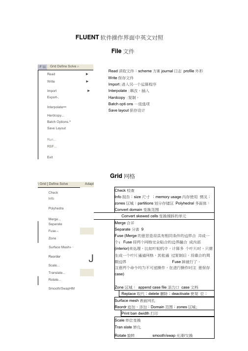
FLUENT 软件操作界面中英文对照File 文件Read 读取文件:scheme 方案journal 日志 profile 外形 Write 保存文件 Import :进入另一个运算程序 Interpolate :窜改,插入Hardcopy :复制,Batch opti ons —组选项Save layout 保存设计 Grid 网格| F 屆 Grid Define Solve i-Read► Write►Import ► Export-, Interpolate —Hardcopy...Batch Options.^Save LayoutRun...RSF...ExitDefine Models模型:solver解算器Pressure based 基于压力Den sity based基于密度末解用丁 pressure based,雀改用Censity based 岀观不苻合秦相36的摄不,请甸pres 羊WE base d Al density based 慎仆则迢.41刊卜 IS 况?北外.血OC ・EHU ^ cotipled >(/^ ptiaw ccupl ed simple 可这孔 & pimple ijEpiso 逞划.--■轟=Sortg 冲-丸布时制* ^jfe-5-6 1844DOden ba&ed 亘工F 吋.压聲血ptessurt ba$«i 适可于那可乐册斤"dens Ply based 把丸“河悴掏t :至殳嗟之一.刑牛可爪門d 的创R 监當歎1一,般如人锻暮叫人丄有用 轴怀,火薩墟迭牛才H5)-0 程:yje8D8-丸布门 1叫;20GS-3-7 10-2ODQ歆;I :谢PrflSsdrfl-Bawd Soker ^Fluflnt 它星英于压力快的束解孤便丹的圮压力修止畀法"求释旳控制片悝足标联式的,擅K 家鮮不町压縮舐Mb 对于町压砂也可旦索麟;Fk«nl 6-3 tl 前的I 板』冷孵臥 B fjS4^r«^at«d &Olvar fli Cfruptod Solvtr,的实也fltje Pr#4iurft-ea5<KJ ScFvAi 约两种虽幵方ib应理拈Fluent 氐J 眇坝犢型小的.它拈垒于曲喪红旳求聲塞,最辑的出H .也桿 艮先■那式的.丰誓■載密式冇Roz AU$hk>谏方法的初和&让Fhwrt 耳有比我甘的求IT 可压胃(说 劫謹力,們耳帕榕式淮冇琴加IF 科限闾辉,倒比还丰A 完荐匚Coupted 的算送t 对子慨站何Hh 地们足便用円匕口讷油皿购 加£未处為 性上世魅端计棒低逢刈趾.擁说的DansJty-Bjiwd Solver F ft St SiMPLEC, P 怡DE 些选以的.闪为進些ffliQl ;力修止鼻袪・不金在这种类崖的我押■中氏现泊I 建址祢匹足整用Fw»ur 护P.sed Solver 堺决昧的利底*implicit 隐式, explicit 显示Space 空间:2D , axisymmetric (转动轴), axisymmetric swirl (漩涡转动轴);Time 时间 :steady 定常,unsteady 非定常 Velocity formulatio n 制定速度: absolute 绝对的;relative 相对的Gradient option 梯度选择:以单元作基础;以节点作基础;以单元作梯度的最小正方形。
Flac3D使用手册

Flac3D使⽤⼿册3INTERFACES3.1General CommentsThere are several instances in geomechanics in which it is desirable to represent planes on which sliding or separation can occur—for example:1.joint,fault or bedding planes in a geologic medium;2.an interface between a foundation and the soil;3.a contact plane between a bin or chute and the material that it contains;4.a contact between two colliding objects;and5.a planar“barrier”in space,which represents a?xed,non-deformable boundaryat an arbitrary position and orientation.FLAC3D provides interfaces that are characterized by Coulomb sliding and/or tensile and shear bonding.Interfaces have the properties of friction,cohesion,dilation,normal and shear stiffnesses, tensile and shear bond strength.Although there is no restriction on the number of interfaces or the complexity of their intersections,it is generally not reasonable to model more than a few simple interfaces with FLAC3D because it is awkward to specify complicated interface geometry.Theprogram3DEC(Itasca1998)is speci?cally designed to model many interacting bodies in three dimensions;it should be used instead of FLAC3D for the more complicated interface problems. Interfaces may also be used to join regions that have different zone sizes.In general,the ATTACH command should be used to join grids together.However,in some circumstances it may be more convenient to use an interface for this purpose.In this case,the interface is prevented from sliding or opening because it does not correspond to any physical entity.3.2FormulationFLAC 3D represents interfaces as collections of triangular elements (interface elements),each of which is de?ned by three nodes (interface nodes).Interface elements can be created at any location in space.Generally,interface elements are attached to a zone surface face;two triangular interface elements are de?ned for every quadrilateral zone face.Interface nodes are then created automatically at every interface element vertex.When another grid surface comes into contact with an interface element,the contact is detected at the interface node,and is characterized by normal and shear stiffnesses,and sliding properties.Each interface element distributes its area to its nodes in a weighted fashion.Each interface node has an associated representative area.The entire interface is thus divided into active interface nodes representing the total area of the interface.Figure 3.1illustrates the relation between interface elements and interface nodes and the representative area associated with an individual node.elementinterfaceFigure 3.1Distribution of representative areas to interface nodesIt is important to note that interfaces are one-sided in FLAC 3D .(This differs from the formulation of two-sided interfaces in two-dimensional FLAC (Itasca 2000).)It may be helpful to think of FLAC 3D interfaces as “shrink-wrap”that is stretched over the desired surface,causing the surface to become sensitive to interpenetration with any other face with which it may come into contact.The fundamental contact relation is de?ned between the interface node and a zone surface face,also known as the target face .The normal direction of the interface force is determined by the orientation of the target face.During each timestep,the absolute normal penetration and the relative shear velocity are calculated for each interface node and its contacting target face.Both of these values are then used by the interface constitutive model to calculate a normal force and a shear-force vector.The constitutive model is de?ned by a linear Coulomb shear-strength criterion that limits the shear force acting at an interface node,normal and shear stiffnesses,tensile and shear bond strengths,and a dilation angle that causes an increase in effective normal force on the target face after the shear-strength limit is reached.By default,pore pressure is used in the interface effective stress calculation.This option can be activated/deactivated using the command INTERFACE i effective=on/off.Figure3.2 illustrates the components of the constitutive model acting at interface node(P).Figure3.2Components of the bonded interface constitutive modelThe normal and shear forces that describe the elastic interface response are determined at calculation time(t+ t)using the following relations.F(t+ t)n=k n u n A+σn A(3.1)F(t+ t) si =F(t)si+k s u(t+(1/2) t)siA+σsi Awhere F(t+ t)n is the normal force at time(t+ t)[force];F(t+ t)si is the shear force vector at time(t+ t)[force];u n is the absolute normal penetration of the interface nodeinto the target face[displacement];u si is the incremental relative shear displacement vector[displacement];σn is the additional normal stress added due to interface stressinitialization[force/displacement];k n is the normal stiffness[stress/displacement];k s is the shear stiffness[stress/displacement];σsi is the additional shear stress vector due to interface stressinitialization;andA is the representative area associated with the interface node[length2].The inelastic interface logic works in the following way:(1)Bonded interface—The interface remains elastic if stresses remain below the bond strengths:there is a shear bond strength as well as a tensile bond strength.The nor-mal bond strength is set using the tension interface property keyword.The command INTERFACE n prop sbratio=sbr sets the shear bond strength to sbr times the normal bond strength.The default value of sbratio(if not given)is100.0.The bond breaks if either the shear stress exceeds the shear strength,or the tensile effective normal stress exceeds the normal strength.Note that giving sbratio alone does not cause a bond to be established; the tensile bond strength must also be set.(2)Slip while bonded—An intact bond,by default,prevents all yield behavior(slip and separation).There is an optional property switch(bslip)that causes just separationto be prevented if the bond is intact(but allows shear yield,under the control of the friction and cohesion parameters,using abs(F n)as the normal force).The command to allow/disallow slip for a bonded interface segment isINTER n PROP bslip=onbslip=offThe default state of bslip(if not given)is off.(3)Coulomb sliding—A bond is either intact or broken.If it is broken,then the behaviorof the interface segment is determined by the friction and cohesion(and of course the stiffnesses).This is the default behavior,if bond strengths are not set(zero).A broken bond segment cannot take effective tension(which may occur under compressive normal force,if the pore pressure is greater).The shear force is zero(for a non-bonded segment)if the effective normal force is tensile or zero.The Coulomb shear-strength criterion limits the shear force by the following relation.F smax=cA+tanφ(F n?pA)(3.2)where c is the cohesion[stress]along the interface;φis the friction angle[degrees]of the interface surface;andp is pore pressure(interpolated from the target face),provided the keywordeffective=off has not been issued for the interface.If the criterion is satis?ed(i.e.,if|F s|≥F smax),then sliding is assumed to occur,and |F s|=F smax,with the direction of shear force preserved.During sliding,shear displacement may cause an increase in the effective normal stress on the joint,according to the relation:σn:=σn+|F s|o?F smaxAk s tanψk n(3.3)whereψis the dilation angle[degrees]of the interface surface;and|F s|o is the magnitude of shear force before the above correction is made.On printout(PRINT interface n prop tens),the value of tension denotes if a bond is intact or broken (or not set)—non-zero or zero,respectively.The normal and shear forces calculated at the interface nodes are distributed in equal and opposite directions to both the target face and the face to which the interface node is connected(the host face). Weighting functions are used to distribute the forces to the gridpoints on each face.The interface stiffnesses are added to the accumulated stiffnesses at gridpoints on both sides of the interface,in order to maintain numerical stability.Interface contacts are detected only at interface nodes,and contact forces are transferred only at interface nodes.The stress state associated with a node is assumed to be uniformly distributed over the entire representative area of the node.Interface properties are associated with each node; properties may vary from node to node.By default,the effect of pore pressure is included in the interface calculation by using effective stress as the basis for the slip condition.(The interface pore pressure is interpolated from the target face.)This applies either in CONFIG?uid mode,or if pore pressures are assigned with the WATER table or INITIAL pp command without specifying CONFIG?uid.The user can switch options for interface i by using the command INTERFACE i effective=on/off.By default,in the FLAC3D logic,?uid?ow—saturated or unsaturated—is carried across an interface,provided the interface keyword maxedge is not used for that particular interface.The permeable interface option can be deactivated/reactivated for interface i by using the command INTERFACE i perm=on/off.Note that if the keyword maxedge is used,and perm is on for a particular interface,a warning is issued to inform the user that this interface will be considered as impermeable to?uid?ow.(Note that, for?uid?ow calculation only,a mechanical model must be present.Also,the command CYCLE 0with SET mech on should be used to initialize the weighting factors used to transfer?uid?ow information across the interface.)No pressure drop normal to the joint and no in? uence of normal displacement on pore pressure are calculated.Also,?ow of?uid along the interface is not modeled.3.3Creation of Interface GeometryInterfaces are created with the INTERFACE command.For cases in which an interface is required between two separate grids in the model,the command INTERFACE i face range...should be used to attach an interface to one of the grid surfaces.This command generates interface elements for interface i along all surface zone faces with a center point that fall within a speci?ed range.Any surfaces on which an interface is to be created must be generated initially with some separation between the adjacent surfaces;it must be possible to specify an existing surface in order to create the interface elements. (Also,a gap must be speci?ed between the two grids because the grid generator will automatically merge surface gridpoints if they are created at the same location in space.)By default,two interface elements are created for each zone face.The number of interface elements can be increased by using the command INTERFACE i maxedge v.*This causes all interface elements with edge lengths larger than v to subdivide into smaller elements until their lengths are smaller than v.This command can be used to increase the resolution and decrease arching of forces in portions of a model that have large contrasts in zone size across an interface.The following rules should be followed when using interface elements in FLAC3D.1.If a smaller surface area contacts a larger surface area(e.g.,a small block restingon a large block),the interface should be attached to the smaller region.2.If there is a difference in zone density between two adjacent grids,the interfaceshould be attached to the grid with the greater zone density(i.e.,the greaternumber of zones within the same area).3.The size of interface elements should always be equal to or smaller than thetarget faces with which they will come into contact.If this is not the case,theinterface elements should be subdivided into smaller elements.4.Interface elements should be limited to grid surfaces that will actually comeinto contact with another grid.A simple example illustrating the procedure for interface creation is provided in Example3.1.The example is a block specimen containing a single joint dipping at an angle of45?.Example3.1Creating a model with a dipping joint;Create Basegen zone brick size333&p0(0,0,0)p1(3,0,0)p2(0,3,0)p3(0,0,1.5)&p4(3,3,0)p5(0,3,1.5)p6(3,0,4.5)p7(3,3,4.5)group Base*Note that if CONFIG?uid is invoked,and perm is on for a particular interface,specifying maxedge for that interface will automatically make it impermeable.Do not specify maxedge if?ow across the interface is desired.;Create Top-1unit high for initial spacinggen zone brick size333&p0(0,0,2.5)p1(3,0,5.5)p2(0,3,2.5)p3(0,0,7)&p4(3,3,5.5)p5(0,3,7)p6(3,0,7)p7(3,3,7)group Top range group Base not;;Create interface elements on the top surface of the baseinterface1face range plane norm(-1,0,1)origin(1.5,1.5,3)dist0.1;plot create view_intplot add surfaceplot add interface redplot showpause;;Lower top to complete geometryini z add-1.0range group Topsave int.savFigure3.3shows the grid before the interface is created.Two sub-grid groups are de?ned:a Base grid,and a Topgrid.Figure3.4shows the model with the interface elements attached to the Base grid.Figure3.5shows the?nal geometry with the sub-grids moved together.A uniaxial compression test with this model is described later in Section3.4.3.Figure3.3Initial geometry before creation of the interfaceFigure3.4Interface elements addedFigure3.5Final geometry3.4Choice of Material PropertiesAssignment of material properties(particularly stiffnesses)to an interface depends on the way in which the interface is used.Three possibilities are common.The interface may be:1.an arti?cial device to connect two sub-grids together;2.a real interface that is stiff compared to the surrounding material,but which canslip and perhaps open in response to the anticipated loading.(This case alsoencompasses the situation in which stiffnesses are unknown or unimportant,but where slip and/or separation will occur—e.g.,?ow of frictional materialin a bin);or3.a real interface that is soft enough to in?uence the behavior of the system(e.g.,a joint with soft clay?lling or a dyke containing heavily fractured material).These cases are examined in detail.3.4.1Interface Used to Join Two Sub-gridsIf possible,sub-grids should be joined with the ATTACH command.It is more computationally-ef?cient to use ATTACH than INTERFACE to join sub-grids.See Section3.2.1.2in the User’s Guide, for a description of,and restrictions on,the ATTACH command.Under some circumstances it may be necessary to use an interface to join two sub-grids.This type of interface is assigned high strength properties with the INTERFACE command,thus preventing any slip or separation.(This is the equivalent ofa“glued”interface in FLAC.)Shear and normal stiffnesses must also be provided;values of friction and cohesion are not needed.It is tempting (particularly for people familiar with?nite element methods)to give a very high value for these stiffnesses to prevent movement on the interface.However,FLAC3D does“mass scaling”(see Section1.1.2.6)based on stiffnesses—the response(and solution convergence)will be very slow if very high stiffnesses are speci?ed.It is recommended that the lowest stiffness consistent with small interface deformation be used.A good rule-of-thumb is that k n and k s be set to ten times the equivalent stiffness of the stiffest neighboring zone.The apparent stiffness(expressed in stress-per-distance units)of a zone in the normal direction ismax K+43Gz min(3.4)where K&G are the bulk and shear moduli,respectively;andz min is the smallest width of an adjoining zone in the normal direction—seeFigure3.6.The max[]notation indicates that the maximum value over all zones adjacent to the interface is to be used(e.g.,there may be several materials adjoining the interface).InterfaceFigure3.6Zone dimension used in stiffness calculationTo illustrate the approach,consider Figure3.7,in which two sub-grids of unequal zoning are joined by the commands in Example3.2and are loaded by a pressure on the left-hand part of the upper surface:Example3.2Joining two sub-gridsgen zone brick size444p00,0,0p14,0,0p20,4,0p30,0,2gen zone brick size884p00,0,3p14,0,3p20,4,3p30,0,5inter1face range z 2.9,3.1inter1prop kn300e9ks300e9tens1e10SBRATIO=1ini z add-1.0range z 2.9,5.1model elasprop bulk8e9shear5e9fix z range z-.1.1fix x range x-.1.1fix x range x 3.9 4.1fix y range y-.1.1fix y range y 3.9 4.1apply szz-1e6range z 3.9 4.1x0,2y0,2hist unbalsolvesave join.savThe value of(K+4G/3)is15GPa,and the minimum zone size adjacent to the interface is 0.5m.Hence,we choose both shear stiffness and normal stiffness to be150×109/0.5—i.e., k n=k s=3×10¹¹Pa/m.The resulting contours of z-displacement are shown in Figure3.8.Compare this result to that for a single grid,shown in Figure3.7in the User’s Guide.This plot is at the same scale and contour intervals as Figure3.8.The two plots are almost identical,which indicates that the interface does not affect the behavior to any great extent.The prescription given in Eq.(3.4)is reasonable if the materials on the two sides of the interface are similar,and variations ofstiffness occur only in the lateral directions.However,if the material on one side of the interface is much stiffer than that on the other,then Eq.(3.4)should be applied to the softer side.In this case,the deformability of the whole system is dominated by the soft side;making the interface stiffness ten times the soft-side stiffness will ensure that the interface has minimal in?uence on system compliance.Figure3.7Two unequal sub-grids joined by an interfaceFigure3.8Vertical displacement contours—two joined grids3.4.2Real Interface—Slip and Separation OnlyIn this case,we simply need to provide a means for one sub-grid to slide and/or open relative to another sub-grid.The friction(and perhaps cohesion,dilation,and tensile strength)is important, but the elastic stiffness is not.The approach of Section3.4.1is used here to determine k n and k s. However,the other material properties are given real values(see Section3.4.3for advice on choice of properties).As an example,we can allow slip in a bin-?ow problem,as shown in Figure3.9,corresponding to the data?le inExample3.3.The bond strengths are not set(i.e.,they default to zero);the interface stiffnesses are set to approximately ten times the equivalent stiffness of the neighboring zones.Figure3.9Flow of frictional material in a“bin”Example3.3Slip in a bin-?ow problem;Create Material Zonesgen zone brick size555&p0(0,0,0)p1(3,0,0)p2(0,3,0)p3(0,0,5)&p4(3,3,0)p5(0,5,5)p6(5,0,5)p7(5,5,5) gen zone brick size555p0(0,0,5)edge 5.0 group Material;Create Bin Zonesgen zone brick size155&p0(4,1,0)p1add(3,0,0)p2add(0,3,0)&p3add(2,0,5)p4add(3,6,0)p5add(2,5,5)&p6add(3,0,5)p7add(3,6,5)gen zone brick size155&p0(6,1,5)p1add(1,0,0)p2add(0,5,0)&p3add(0,0,5)p4add(1,6,0)p5add(0,5,5)&p6add(1,0,5)p7add(1,6,5)gen zone brick size515&p0(1,4,0)p1add(3,0,0)p2add(0,3,0)&p3add(0,2,5)p4add(6,3,0)p5add(0,3,5)&p6add(5,2,5)p7add(6,3,5)gen zone brick size515&p0(1,6,5)p1add(5,0,0)p2add(0,1,0)&p3add(0,0,5)p4add(6,1,0)p5add(0,1,5)&p6add(5,0,5)p7add(6,1,5)group Bin range group Material not;Create named range synonymsrange name=Bin group Binrange name=Material group Material;Assign models to groupsmodel mohr range Materialmodel elas range Bin;Create interface elementsint1face ran plane ori(4,0,0)nor(-5,0,2)dist0.01z(0,5)y(1,6) int2face ran plane ori(0,4,0)nor(0,-5,2)dist0.01z(0,5)x(1,6) int1face ran x 5.9 6.1y16z510int2face ran x16y 5.9 6.1z510int1maxedge0.55int2maxedge0.55;Move bin toward materialini x add-1.0range Binini y add-1.0range Bin;Assign propertiesprop shear1e8bulk2e8fric30range Materialprop shear1e8bulk2e8range Binini den2000int1prop ks2e9kn2e9fric15int2prop ks2e9kn2e9fric15;Assign Boundary Conditionsfix x range x-0.10.1any x 5.9 6.1anyfix y range y-0.10.1any y 5.9 6.1anyfix z range z-0.10.1Bin;Monitor historieshist unbalhist gp zdisp(6,6,10)hist gp zdisp(0,0,10)hist gp zdisp(0,0,0);Settingsset largeset grav0,0,-10;Cyclingstep4000save bin.sav3.4.3All Properties Have Physical Signi?canceIn this case,properties should be derived from tests on real joints*(suitably scaled to account for size effect),or from published data on materials similar to the material being modeled.However, the comments of Section3.4.1also apply here with respect to the maximum stiffnesses that are reasonable to use.If the physical normal and shear stiffnesses are less than ten times the equivalent stiffness of adjacent zones,then there is no problem in using physical values.If the ratio is much more than ten,the solution time will be signi?cantly longer than for the case in which the ratio is limited to ten,without much change in the behavior of the system.Serious consideration should be given to reducing supplied values of normal and shear stiffnesses to improve solution ef?ciency. There may also be problems with interpenetration if the normal stiffness,k n,is very low.A rough estimate should be made of the joint normal displacement that would result from the application of typical stresses in the system(u=σ/k n).This displacement should be small compared to a typical zone size.If it is greater than,say,10%of an adjacent zone size,then there is either an error in one of the numbers,or the stiffness should be increased if calculations are to be done in large-strain mode.Joint properties are conventionally derived from laboratory testing(e.g.,triaxial and direct shear tests).These tests can supply physical properties for joint friction angle,cohesion,dilation angle, and tensile strength,as well as joint normal and shear stiffnesses.The joint cohesion and friction angle correspond to the parameters in the Coulomb strength criterion?described in Section3.2. Values for normal and shear stiffnesses for rock joints typically can range from roughly10to100 MPa/m for joints with soft clay in-?lling,to over100GPa/m for tight joints in granite and basalt. Published data on stiffness properties for rock joints are limited;summaries of data can be found in Kulhawy(1975),Rosso(1976),and Bandis et al.(1983).Approximate stiffness values can be back-calculated from information on the deformability and joint structure in the jointed rock mass and the deformability of the intact rock.If the jointed rock mass is assumed to have the same deformational response as an equivalent elastic continuum,then relations can be derived between jointed rock properties and equivalent continuum properties. For uniaxial loading of rock containing a single set of uniformly spaced joints oriented normal to the direction of loading,the following relation applies.1=1r +1n(3.5)*“Joint”is used here as a generic term.The Coulomb yield surface provides a reasonable approximation for joint strength for most engi-neering calculations.More complex joint models are available which include,for example,effects of continuous yielding and displacement weakening.For analysis with other joint models,the user is referred to UDEC(Itasca1996).ork n=E E rs(E r?E)(3.6)where E=rock mass Young’s modulus;E r=intact rock Young’s modulus;k n=joint normal stiffness;ands=joint spacing.A similar expression can be derived for joint shear stiffness:k s=G G rs(G r?G)(3.7)where G=rock mass shear modulus;G r=intact rock shear modulus;andk s=joint shear stiffness.The equivalent continuum assumption,when extended to three orthogonal joint sets,produces the following relations:E i=1r+1i ni1(i=1,2,3)(3.8)G ij=1G r+1s i k si+1s j k sj1(i,j=1,2,3)(3.9)Several expressions have been derived for two-and three-dimensional characterizations and multiple joint sets.References for these derivations can be found in Singh(1973),Gerrard(1982(a)and (b)),and Fossum(1985).Published strength properties for joints are more readily available than stiffness properties.Sum-maries can be found,for example,in Jaeger and Cook(1979),Kulhawy(1975),and Barton(1976). Friction angles can vary from less than10?for smooth joints in weak rock,such as tuff,to over 50?for rough joints in hard rock,such as granite.Joint cohesion can range from zero to values approaching the compressive strength of the surrounding rock.It is important to recognize that joint properties measured in the laboratory typically are not rep-resentative of those for real joints in the?eld.Scale dependence of joint properties is a major question in rock mechanics.Often,the only way to guide the choice of appropriate parameters is by comparison to similar joint properties derived from?eld tests.However,?eld test observations are extremely limited.Some results are reported by Kulhawy(1975).The following example illustrates an application of the interface logic to simulate the physical response of a rock joint subjected to normal and shear loading.The model represents a direct shear test,which consists of a single horizontal joint that is?rst subjected to a normal con?ning stress, and then to a unidirectional shear displacement.Figure3.10shows the model.Figure3.10Direct shear test modelFirst,a normal stress of10MPa is applied that is representative of the con?ning stress acting on the joint.A horizontal velocity is then applied to the top sub-grid to produce a shear displacement along the interface.For demonstration purposes,we only apply a small shear displacement of less than2mm to this model.The average normal and shear stresses,and normal and shear displacements along the joint,are measured with a FISH function.With this information we can determine the shear strength and dilation that are produced.The data?le for this test is contained in Example3.4.Example3.4Direct shear testtitleDirect shear testgen zone brick size12110p0406p11606p2416p34011 gen zone brick size20110p12000p2010p3005range name bot z05range name top z611interface1face range z5int1prop ks4e4kn4e4fric30dil6;tension1e10bslip=onini z add-1.0range top;plo surf lorange interface white axes blackmodel eprop bulk45e3sh30e3fix x y z range z0fix x range x0fix x range x20apply nstress-10range z10step0plot contour szz interface white axes blacksolvesave dsta.savini xvel5e-7range topfix xvel range topdef ini_jdispvalnd=0.0count=0.0p_in=i_node_head(i_head)loop while p_in#nullif in_ztarget(p_in)#null thenvalnd=valnd+in_pen(p_in)count=count+ 1.0end_ifp_in=in_next(p_in)end_loopnjdisp0=valnd/countendini_jdispdef sstavvalns=0.0valss=0.0valsd=0.0valnd=0.0count=0.0p_in=i_node_head(i_head)loop while p_in#nullif in_ztarget(p_in)#null thenvalns=valns+in_nstr(p_in)*in_area(p_in) valss=valss+in_sstr(p_in,1)*in_area(p_in) valsd=valsd+in_sdisp(p_in,1)valnd=valnd+in_pen(p_in)count=count+ 1.0end_ifp_in=in_next(p_in)end_loopsstav=valss/(12.0*1.0)nstav=valns/(12.0*1.0)sjdisp=valsd/countnjdisp=valnd/count-njdisp0endhist ns1hist sstav nstav sjdisp njdispini xdis0ydis0zdis0step2500save dst.savplot his-1vs-3pauseplot his-4vs-3pauseretThe average shear stress versus shear displacement along the joint is plotted in Figure3.11,and the average normal displacement versus shear displacement is plotted in Figure3.12.These plots indicate that joint slip occurs for the prescribed properties and conditions.The loading slope in Figure3.11is initially linear and then becomes nonlinear as interface nodes begin to fail until a peak shear strength of approximately5.8MPa is reached.As indicated in Figure3.12,the joint begins to dilate when the interface nodes begin to fail in shear.。
一类动力学方程及流体力学方程解的Gevrey类正则性
Boltzmann 方程 . . . . . . . . . . . . . . . . . . . . . . . . 碰撞算子 Q(f, f ) 的基本性质 . . . . . . . . . . . . . . . . . Fokker-Planck 方程、Landau 方程以及 Boltzmann 方程线性 化模型 . . . . . . . . . . . . . . . . . . . . . . . . . . . . . . Navier-Stokes 方程 . . . . . . . . . . . . . . . . . . . . . . . Gevrey 函数空间 . . . . . . . . . . . . . . . . . . . . . . . .
研究现状及本文主要结果 . . . . . . . . . . . . . . . . . . . . . . . 1.2.1 1.2.2 1.2.3 1.2.4 存在性及唯一性 . . . . . . . . . . . . . . . . . . . . . . . . . 动力学方程的正则性理论: 空间齐次情形 . . . . . . . . . . . 动力学方程的正则性理论: 空间非齐次情形 . . . . . . . . . . Navier-Stokes 方程的正则性理论 . . . . . . . . . . . . . . .
第二章 预备知识 2.1 2.2 2.3 基本记号
Fourier 变换 . . . . . . . . . . . . . . . . . . . . . . . . . . . . . . . 基本函数空间及常用不等式 . . . . . . . . . . . . . . . . . . . . . . 2.3.1 2.3.2 Lp 空间及其性质 . . . . . . . . . . . . . . . . . . . . . . . . Sobolev 空间及其性质 . . . . . . . . . . . . . . . . . . . . .
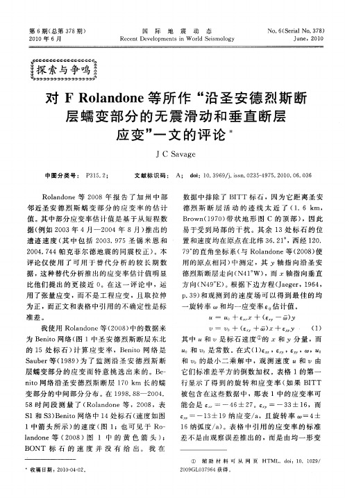
对F Rolandone等所作“沿圣安德烈斯断层蠕变部分的无震滑动和垂直断层应变”一文的评论
21 0 0年 6月
国
际
地
震
动
态
No 6 S ra . 7 ) . ( e il No 3 8
Re e t v l p n si o l es l g c n De eo me t n W rd S imo 对 FRoa d n ln o e等所 作 “ 圣 安德 烈斯 断 沿 层 蠕 变 部 分 的 无 震 滑 动 和 垂 直 断 层
应 变 ’ 文 的评 论 * ’ 一
JC S v g a a e
中 图 分 类 号 : P 1. ; 3 5 2 文 献标 识码 : A; d i 0 3 6 /.sn 0 3 — 9 5 2 1 . 6 0 6 o :1 . 9 9 ] i . 2 54 7 . 0 0 0 . 3 s
用 了 张 量 应 变 , 不 是 工 程 应 变 ,且 取 拉 伸 而
数据 中排 除 了 B TT标石 ,因为 它距 离圣 安 I
德 烈 斯 断 层 活 动 的 迹 线 太 近 了 ( . m, 1 6k Bo (9O 带 状地 形 图 C 的顶 部 ) rwn 1 7 ) ,因 此
R ln o e等 2 0 oa d n 0 8年 报 告 了加 州 中 部 邻 近圣 安 德 烈 斯 蠕 变 部 分 的应 变 率 的估 计 值 。 中部分 应变 率估计 值 是基 于从 短 程数 其 据( 例如 2 0 0 3年 4月 一2 0 0 4年 8月) 出 的 推 遗迹 速 度 ( 中 包 括 2 0 . 7 其 0 3 9 5圣 锡 米 恩 和 20 .4 0 4 7 4帕克 菲 尔德 地震 的同震 校 正 ) 。本 评论仅 使 用 了可 用 于 替代 分 析 的 较 长 期 数 据 ,这种替 代分析 推 出的应 变率 估计 值 明显 比他们 提出 的更 接 近 0 。在 这 一 评 论 中 ,运
Lesson19 Structural Analysis
Basic principles 基本原理
The law of equilibrium is basic in structural analysis.
平衡原理是结构分析的基础。
It is useful in computing external reactions of beams,trusses,frames, arches and other structures, as well as internal stresses.
Structural Analysis
For earthquake forces,a building designed with a conventional rectangular configuration is analysed by the equivalent lateral load method prescribed by the local building code.
如果计算显示反力平衡了荷载(结构、人群、存放的材料等 的重量,车辆荷载,风力和地震力),那么结构就处于静力平衡 状态。
The next step is determination of internal forces and unit stresses in the components of the structure.
保证结构安全的一种方法是确定由荷载产生的应力、应变 比公认的设计规范所容许的应力、应变小。
This determination of stresses and strains in structures is a primary objective of structural analysis.
在结构中确定应力和应变是结构分析的主要的目的。
卿建业副教授 Jianye Ching
5.
Ching, J., Beck, J.L., Porter, K.A. and Shaikhutdinov, R. (2006), Bayesian state estimation method for nonlinear systems and its application to recorded seismic response, ASCE Journal of Engineering Mechanics, 132(4), 396-410. (SCI:0.787 35/107: Cite #: 3)
corresponding author
graduang, J., Au, S.K. and Beck, J.L. (2005), Reliability estimation for dynamic systems subject to stochastic excitations using Subset Simulation with splitting, Computer Methods in Applied Mechanics and Engineering, 194, 1557-1579. (SCI:1.488 17/112; Cite #: 18)
1
2005-2009 教師著作目錄集
11. Ching, J. and Hsieh, Y.-H. (2007), Approximate reliability-based optimization using a three-step Stochastic Design approach with Subset Simulation, ASCE Journal of Engineering Mechanics, 133(4), 481-493. (SCI:0.787 35/107; Cite #:1) 12. Ching, J. and Chen, Y.-C. (2007), Transitional Markov chain Monte Carlo method for Bayesian model updating, model class selection and model averaging, ASCE Journal of Engineering Mechanics, 133(7), 816-832. (SCI:0.787 35/107; Cite #:4) 13. Ching, J. and Hsu, W.-C. (2007), An efficient method of evaluating connectivity reliability of huge infrastructure networks, Computer-Aided Civil and Infrastructure Engineering, 22, 584-596. (SCI:0.861 4/34) 14. Ching, J. and Hsieh, Y.-H. (2007), Local estimation of failure probability function with direct Monte Carlo simulation, ASCE Geotechnical Special Publication. (EI) 15. Ching, J. and Hsu, W.-C. (2008), Transforming probabilistic limit-state constraints into deterministic constraints, Structural Safety, 30, 11-33. (SCI:1.075 11/89; Cite #:1) 16. Ching, J., Chen, Y.C., Chen, J.R. and Phoon, K.K. (2008), Updating uncertainties in soil shear strength parameters with multivariate in-situ and laboratory test data, Sino-Geotechnics, 115, 5-18. (in Chinese) 17. Ching, J., Liao, H.-J., and Sue, J.-W. (2008), Calibration of reliability-based resistance factors for flush drilled soil anchors in Taipei basin, ASCE Journal of Geotechnical and Geoenvironmental Engineering, 134(9), 1348-1363. (SCI:0.746 10/26) 18. Ching, J. and Hsu, W.-C. (2008), Approximate optimization of uncertain systems in high dimensions with multiple reliability constraints, Computer Methods in Applied Mechanics and Engineering, 198, 52-71. (invited paper for special issue) (SCI:1.488 17/112) 19. Ching, J. (2009), Equivalence between reliability and factor of safety, Probabilistic Engineering Mechanics, 24(2), 159-171. (SCI:1.162 29/112) 20. Ching, J. and Hsieh, Y.-H. (2009), Updating reliability of instrumented systems with stochastic simulations, Probabilistic Engineering Mechanics, 24(2), 242-250. (SCI:1.162 29/112) (NSC 95-2221-E-011-057) 21. Ching, J., Porter, K.A. and Beck, J.L. (2009), Propagating uncertainties for loss estimation in performance-based earthquake engineering using moment matching, Structure and Infrastructure Engineering, 5(3), 245-262. (SCI:0.442 53/89) 22. Ching, J., Yen, M.-T., and Lin, H.-D. (2009), Model selection issue in calibrating geotechnical reliability-based resistance factors based on in-situ test data, Structural Safety, 31(5), 420-431. (SCI:1.075 11/89) 23. Ching, J. and Chen, W.-Y. (2009), Approximate reliability-based design with general geotechnical models by stochastic simulation, GeoRisk, 3(2), 58-66. (invited paper for special issue) 24. Ching, J. and Hsieh, Y.H. (2009), Observations in reliability analysis of a 1-D consolidation problem, Journal of GeoEngineering, 4(1), 19-27.
化工设备英文名称大全
化工设备英文名称大全目? ? 录? ?Contents1. 工艺设备Process Equipment 1. 塔Column 11.1.1. 板式塔和填料塔Plate Column and Packed Column 1. 液流型式Liquid – Flow Patterns 2. 泡罩(帽)塔盘Bubble Cap Trays 3. 浮阀塔盘Valve Trays 4. 筛板塔盘Sieve Trays 6. 穿流式塔盘和喷射型塔盘Dual – Flow Trays and Jet Trays 7. 塔盘的支承Supports of Tray 8. 塔底结构及重(再)沸器Bottom Structures and Reboilers 9 . 进料和抽出Feed and Draw – Off 10. 填料Packing 12. 液体分配(布)器,再分配(布)器及填料支持版Liquid Distributors, Redistributors and Support Plates 13. 塔附件??T ower Attachments 14. 楼梯(梯子)和平台Stair and Platform 15CO2吸收塔CO2 Absorber 16再生塔/CO2汽提塔Regenerator / CO2 Stripper 17造粒塔Prill Tower 18. (造粒塔)总图及造粒喷头组装图General Assembly and Prill-Spray Assembly 18. 造粒塔扒料机Prill tower Reclaimer 20. 反应器Reactor 22氨合成塔Ammonia Converter 22聚合釜Polymerizer 24电解槽Cell 26. 隔膜电解槽Diaphragm Cells 26. 水银电解槽Mercury Cells 27. 贮罐Storage Tanks 28浮顶罐Floating Roof Tanks 30. 浮顶型式??Floating Roof Types 32. 浮顶罐的密封形式??Seal Types of Floating Roof Tank 34内浮顶罐??Covered Floating Roof Tanks 35低温贮罐Refrigerated Storage Tanks 36. 蒸发器Evaporators 37. 换热器Heat Exchangers 38换热器的名称Nomenclature of Heat Exchanger 40. 换热器部件Components of Heat Exchanger 40. 固定端头盖(或管箱),壳体及后端头盖型式Types of Stationary Head, Shell and Rear End Head 42. 管板Tube sheets 43. 管子-管板连接,膨胀节及其他零件Tube-Tube Sheet Joints, Expansion Joints and Other Parts 44. 横向折流板和纵向折流板Transverse Baffles and Longitudinal Baffles 46套管式换热器和刮面式换热器Double-Pipe Heat Exchanger and Scraped-Surface Exchanger 47套管式纵向翅片换热器Double Pipe Longitudinal Finned Exchanger 48 板式换热器Plate-Type Exchangers 49蒸汽表面冷凝器,凝汽器Steam Surface Condensers 50空冷器,空气冷却器Air-Cooled Heat Exchangers 51. 空冷器的组合形式Bay Arrangements of Air-Cooled Heat Exchanger 52 . 管束和头盖(管箱)的典型结构Typical Construction of Tube Bundles and Headers 53. 空冷器的驱动装置Drive Arrangements for Air Cooler 54. 翅片Fins 55. 空冷器的温度控制Temperature Control of Air Cooler 56冷却塔,凉水塔(1)Cooling Towers(Ⅰ) 57冷却塔,凉水塔(2)Cooling Towers(Ⅱ) 58. 工业炉Furnace 60管式加热炉Pipe Heater 60. 管式加热炉型式Types of pipe Heaters (pipe Still Heater) 60 . 加热炉Heaters 62. 燃烧器,烧嘴Burners 63. 炉管,联管箱和回弯头Tube, Headers and Return Bends 64 . 管架Tube Supports 65转化炉Reformers (Reforming Furnaces) 66二段转化炉Secondary Reformer 67变换炉Shift Converter 68热回收和废热锅炉Heat Recovery and Waste Heat Boiler 69. 热回收Heat Recovery 69. CO燃烧废热锅炉CO Firing Waste Heat Boiler 70. 第一废热锅炉Primary Waste Heat Boiler 71. 第二废热锅炉Secondary Waste Heat Boiler 72火炬Flare Stacks 73. 混合设备Mixing Equipment 74搅拌器型式(1)Types of Agit ator(Ⅰ) 74搅拌器型式(2)Types of Agitator(Ⅱ) 76混合(搅拌)槽Mixing Tanks 77管道混合器Line Mixers (Flow Mixers) 78静止混合器Static Mixers 79膏状物料及粘性物料混(拌)合设备Paste and Viscous-Material Mixing Equipments 80固体混合机械Solids Mixing Machines 82双螺杆连续混合机Double Screw Continuous Mixer 83. 萃取器Extractors 84连续萃取设备,连续抽提设备Continuous Contact (DifferentialContact) Equipments 84浸提设备Leaching Equipments 86. 旋风分离器、沉清器、过滤器和离心机Cyclone, Decanter, Filter and Centrifuge 87旋风分离器(1)Cyclone Separators (Ⅰ) 87旋风分离器(2)Cyclone Separators (Ⅱ) 88气体洗涤器Gas Scrubbers 90沉降罐,澄清器Gravity Settlers (Decanters) 92过滤机Filter 93压滤机Pressure Filters 93叶滤机Pressure Leaf Filters 94袋式过滤器Bag Filters 95转鼓真空过滤机Rotary-Drum Vacuum Filter 96离心式分离机Centrifugal Separator 97. 双鼓真空离心过滤机Double-Bowl Vacuum Centrifuge 97. 离心机Centrifuges 98. 静止叶片型离心式分离器Stationary Vane Type Centrifugal Separators 100. 干燥器Dryers 101间接干燥器Indirect Dryers 101直接干燥器Direct Dryers 102喷雾干燥器Spray Dryers 104. 雾化喷头,喷雾嘴,雾化器Spray Nozzles (Atomizers) 105气流(气动)输送干燥器? ? Pneumatic Conveyor Dryers 106. 其他? ? Miscellaneous 107石油炼制中的流化过程? ? Fluidization Processes in Petroleum Refinery107. 流态化? ? Fluidization 108. 流化床分布器? ? Distributors for Fluidized Bed 109破沫器及其应用? ? Demister and Its Applications 110. 破沫网的安装和纤维除雾器? ? Installation of Mesh and Fiber Mist Eliminator 111设备的支座和封头? ? Supports and Heads of Equipments 112 立式容器的外部保温? ? External Thermal Insulation for Vertical Vessel 1132. 泵? ? Pump 114. 各种型式的泵(1) Various Types of P ump (Ⅰ) 114各种型式的泵(2) Various Types of Pump (Ⅱ) 116各种型式的泵(3) Various Types of Pump (Ⅲ) 117各种型式的泵(4) Various Type s of Pump (Ⅳ) 118. 离心泵(1)? ? Centrifugal Pump(Ⅰ) 119离心泵(2)? ? Centrifugal Pump(Ⅱ) 120离心泵(3)? ? Centrifugal Pump(Ⅲ) 121. 管道泵? ? Inline Pump 122. 双作用蒸汽往复泵? ? Duplex Acting Steam-Driven Reciprocating Pump 123 . 双作用活塞式往复泵? ? Double Action Reciprocating Pump, Bucket Type 124 . 混流泵??Mixed-Flow Pump 126. 计量泵? ? Metering Pumps 127. 喷射泵? ? Jet Pumps 128. 喷射装置? ? Ejector Units 129喷射器的结构? ? Ejector Structures 1303. 压缩机、鼓风机和风机? ? Compressors Blowers and Fans 131. 螺杆压缩机? ? Screw Compressors 131. 旋转式螺杆压缩机? ? Rotary Helical Screw Compressors 132 . 活塞式压缩机? ? Piston Compressors 133. 往复式压缩机? ? Reciprocating Compressors 134. 低密度聚乙烯(超)高压压缩机? ? High Pressure Compressor forLow Density Polyethylene Process 136高压气缸和中心型组合阀? ? High-Pressure Cylinder and Central Valve 138 卸荷阀并及其他阀? ? Unloading Valve and Other Valves 140. 水平剖分式离心压缩机? ? Horizontally Split Centrifugal Compressor 142 . 鼓风机,压气机? ? Blowers 144. 风机? ? Fans 146. 典型的空气压缩机装置? ? Typical Compressor Installation 1484. 输送机和提升机? ?Conveyor and Elevator 149. 垂直提升(输送)机? ? Vertical Elevator (Conveyor) 149斗式提升机? ? Bucket Elevator 149垂直提升输送机和箱类提升机? ? Vertical Rising Conveyor and Case Elevator 150双带提升机? ? Twin Riser 151. 带式输送机? ? Band (Belt) Conveyor 152带式输送机示意图? ? Band Conveyor Sketch 152输送机系统? ? Conveyor Systems 153带式输送机? ? Band Conveyor 154中心距超过600英尺的单轮传动带式输送机用的张紧装置? ? Take-up Unit for Single Drum Drive Belt Conveyor Exceeding 600 Feet Centers 155双轮传动带式输送机的张紧装置? ? Take-up Unit for Dual Drum Drive Belt Conveyor 156拼装式皮带运输机和移动式皮带运输机? ? Pre-built Sectional Belt Conveyor and Mobile Belt Conveyor 157. 螺旋输送机? ? Screw Conveyor 158. 吊挂式链输送机和振动输送机? ? Chain Trolley Conveyor and Vibrating Conveyor 159吊挂式链输送机部件? ? Units of Chain Trolley Conveyor 160. 辊子输送机? ? Roller Conveyors 162. 惰轮(托辊)型式? ? Types of Idlers 163托辊(惰轮)结构? ? Construction of Iders 1645. 破碎和筛分设备? ? Crushing and Screening Equipment 166. 颚式破碎机? ? Jaw crusher 166. 颚式冲击破碎机? ? Impact Jaw Crusher 168. 回转球形破碎机? ? Gyrasphere Crusher 169. 盘式回转破碎机? ? Tray Type Gyratory Crusher 170. 液压锥形破碎机和冲击式破碎机(叶片破碎机)? ? Hydraulic Cone Crusher and Impact Crusher (Impeller Breaker) 172 . 辊子粉碎机? ? Roller Mill 173. 双轴锤击破碎机? ? Double Shaft Hammer Mill 174. 球磨机? ? Ball Mill 176. 干燥粉磨机? ? Dryer-Pulveriser 177. 返混设备布置? ? Layout of Back mixing Equipment 178. 振动筛? ? Vibrating Screen 179. 分级机? ? Classifiers 1806. 塑料和橡胶加工成型机械? ???Forming Machine For Plastics and Rubber181. 挤压机? ? Extruder 181. 螺杆注塑机? ? Screw Injection Molding Machine 182. 聚氯乙烯辊压机生产线? ? Calender Line for PVC Production 183. 四辊辊压机? ? Four-Roll Calender 1847. 给料机,称量器和包装机? ? Feeder, Weighing and Bagging Machine 186 . 振动给料机? ? Vibrating Feeder 186. 电振动给料机? ? Electric Vibrating Feeder 188. 板式给料机? ? Apron Feeder 189. (粉末)均匀自动给料机? ? Smooth Auto-Feeder 190. 带式计量秤? ? Dosing Belt Weigher 191. 定量给料秤? ? Constant Feed Weigher 192. 自动装袋系统??Automatic Bagging System 1938. 汽轮机? ? Steam Turbine 194. 汽轮机的分类(1)? ? Classification of Steam Turb ines (Ⅰ) 194汽轮机的分类(2)? ? Classification of Steam Turbines (Ⅱ) 196. 汽轮机的循环? ? Steam Turbine Cycles 197. 汽轮机供汽方式? ???Methods of Steam Supply to a Turbine 198. 单级汽轮机? ? Single Stage Steam Turbine 199. 冲动式汽轮机? ? Impulse Turbines 200. 汽轮机轴封? ? Turbine Glands and Gland Sealings 202. 汽轮机的润滑? ? Lubrication of Steam Turbine 204. 汽轮机调速器及调速? ? Governors and Governing of Steam Turbine 206 . 汽轮机调速器??Turbine Governor 208. 超速脱扣装置(保安器)??Overspeed Tripping Device 210. 汽轮机的安装??Installation of Steam Turbine 2119. 锅炉??Boiler 212. 火管锅炉及水管锅炉的基本型式??Basic Patterns for Fire and Water Tube Boiler 212. 椭圆管板换热器??Ellipsoidal Shell and Tube Heat Exchanger 213. 水冷管夹套换热器??Cooling Tubes and Jacket Heat Exchanger 214. 蒸汽净化及锅筒内件(1)??Steam Purification and Drum Internals (Ⅰ) 215蒸汽净化及锅筒内件(2)??Steam Purification and Drum Internals (Ⅱ) 216蒸汽净化及锅筒内件(3)??Steam Purification and Drum Internals (Ⅲ) 218蒸汽净化及锅筒内件(4)??Steam Purification and Drum Internals (Ⅳ) 219 . 过热器??Superheater 220. 减温器??Attemperators 221. 空气预热器??Air Preheater 222. 炉排??Grates 224. 下饲炉排??Underfeed Stoker 225. 喷燃器,燃烧器??Burners 226. 省煤器??Economizer 228. 抛煤机??Spreader Feeders 229. 磨煤机??Pulverizers 23010. 机械零件??Machine Element 231. 万向节??FUniversal Joints 231. 联轴器??Couplings 232. 液力联轴器(1)??Fluid Couplings (Ⅰ) 234液力联轴器(2)??Fluid Couplings (Ⅱ) 235. 轴颈密封,圆周密封??Circumferential Seals 236. 端面密封,轴封,轴端连接件??Face Seals, Shaft Sealings and End Fittings 237. 滚子轴承,滚柱轴承??Roller Bearings 238. 球轴承,滚珠轴承 Ball Bearings 239. 加油机构??Oiling Devices 240. 紧固件??Fastener 241螺栓和双头螺柱??Bolts and Studs (stud bolts) 241螺钉的头部和端部型式??Heads and Points of Screw 242螺母??Nuts 243非螺纹紧固件??Non-threaded Fasteners 24411. 配管(管路)和管件??Piping and Fitting 245. 阀杆与阀盖结构??Valve Stem and Bonnet Designs 245. 阀门(1)??Valves(Ⅰ) 246阀门(2)??Valves(Ⅱ) 248阀门(3)??Valves(Ⅲ) 249阀门(4)??Valves(Ⅳ) 250. 闸阀??Gate Valve 251. 截止阀??Globe Valve 252. 球阀??Ball Valve 253. 止回阀??Check Valve 254. 弹簧安全泄压阀??Spring Safety-Relief Valve 255. 液面控制浮球阀??Pilot Operated Ball Float Valve 256. 波纹管密封闸门阀??Bellows Sealed Gate Valve 257. 热膨胀阀??Thermo Expansion Valve 258. 阀门操纵机构??Valve Operating Mechanisms 259. 蒸汽疏水阀(器)和空气疏水阀(器)??Steam Traps and Air Traps 260. 管道附件??Pipe Line Fitments 262. 法兰、法兰密封面及垫片??Flanges, Flange Facings and Gaskets 264. 填料??Packings 266. 管件??Pipe Fitting 267法兰管件??Flanged Fittings 267螺纹管件??Threaded Fittings 268钢焊接管件??Steel-Welding Fittings 269. 塑料压接管接头??Plastics Compression Joints 270. 预制弯管与膨胀节??Fabricated Pipe Bends and Expansion Joints 271. 管子连接??Joints in Tubing and Pipe 272. 管道绝热??Piping Insulation 273. 管吊与管支架??Pipe Hangers and Pipe Supports 274. 急救冲洗和洗眼站??Safety Shower and Eyewash Station? ?? ?? ?Hose??Station??软管站 27612. 量测仪表??Instrumentation 277. 液位(面)计??Level Gage 277就地安装直读液面计??Locally Mounted Direct Reading Level Gages 277 浮筒式液面计??Displacement Type Level Gages 278液面调节器及液位开关??Level Controllers and Switches 279. 压力测量仪表??Pressure Instruments 280液体压力计??Manometers 282压力测量的新成果??New Developments in Pressure Measurements 283压力表的安装??Installation of Pressure Guage 284. 流量测量元件??Flow Measuring Element 285速率式流量计??Inferential Meters① (Fluid Velocity Meter) 285 . 涡轮流量计??Turbine Meter 285. 漩涡流量计??Vortex flow meter 286. 漩涡流量计测量系统??Vortex Flow meter Measurement System 287一次流量元件??Primary Flow Elements 288容积式流量计??Positive Displacement Type Flow Meters 290 可变面积(定压降)式流量计??Variable Area Type Flow Meters 292差压流量计的安装? ?Installation of Head Meters 294面积式流量计及计量泵??Area Meters and metering pumps 296其他流量计(1)??Other Flow Meters(Ⅰ) 297其他流量计(2)??Other Flow Meters(Ⅱ) 298. 温度计??Thermometer 299热电偶??Thermocouple 299液体膨胀温度计及双金属温度计??Liquid Expansion and BimetallicThermometer 300电阻式温度计及热敏电阻??Resistance Thermometer and Thermistor 302 压力式温度计??Filled System Thermometer 303 辐射高温计??Radiation Pyrometer 304光学高温计??Optical Pyrometer 305电动指示调节器??Electritic Indicating Controller 306气动指示调节器??Pneumatic Indicating Controller 307多点长图温度记录仪??Multi-Point Long Chart Temperature Recorder 308 控制操作箱??Control Station 309记录纸??Charts 310. 变送器??Transmitter 311压力变送器??Pressure Transmitter 311差压变送器??Differential Pressure Transmitters 312气动温度变送器??Pneumatic Temperature Transmitter 314物位变送器??Level Transmitters 315. 调节(控制)器??Controller 316液位调节器??Liquid Level Controller 316气动调节器??Pneumatic Controller 317弹簧管调节器??Bourdon Tube Controller 318. 调节阀??Control Valve 319薄膜及活塞执行机构??Diaphragm and Piston Actuators 320调节阀阀盖??Bonnets of Control Valve 321调节阀阀体(1)??Control Valve Bodies (Ⅰ) 322调节阀阀体(2)??Control Valve Bodies (Ⅱ) 323阀芯及笼式阀芯??Valve plugs and Cages 324阀内组件(组成)部分??Components Valve Trim① 325调节阀的作用及导向??Acting and Guiding of Control Valve 326调节阀定位器??Positioner of Control Valve 327调节阀手动机构??Handjack Assembly of Control Valve 328气动活塞定位器??Pneumatic Piston Positioner 329. 氧分析器??Oxygen Analysis Equipment 330. 二氧化碳分析器??Carbon Dioxide Analyzer 332. PH计??pH meters 333. 粘度测量仪表??Viscosity Measuring Instruments 334. 比重仪表??Specific Gravity Instrument 336. 速度测量与控制??Speed Measurement and Control 337. 仪表盘??Instrument Panels 338. 温度控制??Temperature Control 340. 信号系统 Annunciators Systems 341集中式信号器??Integral Annunciators 342分离式信号器及半模拟式信号器??Remote Annunciator and Semigraphic Annunciator 343. 继动器??Relays 344. 仪表管件及仪表箱??Instrumentation Tube Fittings and Housings 346. 仪表图例符号及名称??Instrumentation Symbols and Identifications 348 . 总体分散控制系统(1)??Total Di stributed Control System(Ⅰ) 350. 总体分散系统(2)??Total Distributed Control System(Ⅱ) 351 . 总体分散系统(3)??Total Distribu ted Control System(Ⅲ) 352 . 总体分散系统(4)??Total Distributed Control System(Ⅳ) 353 . 总体分散系统(5)??Total Distributed Control System(Ⅴ) 354 . 总体分散系统(6)??Total Distributed Control System(Ⅵ) 35513. 电气工程??Electrical Engineering 356. 旋转电机??Electrical Rotating Machine 356直流电机??Direct-Current Machine 356直流发电机??Direct-Current Generator 357AC换向电机??AC Commutator Machine 358交流电动机??Alternating-Current Motor 359滑环式感应电动机??Slip-ring Type Induction Motor 360无刷同步电动机??Brushless Synchronous Motor 362同步电动机的无刷励磁??Brushless Excitation of Synchronous Motor 363 线槽和绕组??Slots and Windings 364. 变压器??Transformer 365油浸式变压器正视图??Oil Immersed Transformer Front View 365油浸式变压器侧视图??Oil Immersed Transformer Side View 366油浸式变压器外视图??Oil Immersed Transformer Exterior 367 . 整流器和电池??Rectifier and Battery 368整流器??Rectifier 368原电池(1)??Primary Batteries(Ⅰ) 369原电池(2)??Primary Batteries(Ⅱ) 370. 高压开关装置??High Voltage Switchgear 372金属封闭式开关装置??Metal-Enclosed Switchgear 372金属高压开关柜??Metal-Clad High-Voltage Cubicle 373六氟化硫断路器??SF6 Circuit-Breaker 374T型断路器??T-Breaker 376电动机操纵机构??Motor Drive 377. 低压开关??Low-Voltage Switches 378限流空气断器??Currentt-Limiting Air-Break Circuit-Breaker 378塑料外壳断路器??Moulded Case Circuit-Breaker 379控制开关??Control Switches 380. 按钮开关??Pushbutton Switches 382. 凸轮旋转开关??Cam Switches 384. 电磁设备??Electromagnetic Apparatus 386电磁机构和器件??Electromagnetic Mechanism and Devices 386电磁继电器??Electromagnetic Relays 388电压调整继电器??Voltage Regulating Relay 390. 电气防爆??Electrical Explosion-proof 391危险场所内的电力和照明安装??Power and Lighting Installation in Hazardous Location 391防爆设备??Explosion-proof Apparatus 392. 供电系统??Power Supply System 394热电厂??Thermal Power Plant 394. 节能发电厂??Energy Saving Power plant 396变电所屋内配电装置??Indoor Installations of Electric Substation 398 铁塔及电杆??T owers and Poles 399静电除尘器??Electrostatic Precipitator 400. 内线??Interior Wiring 401电缆??Cables 401熔断器??Fuses 404连接器和端子??Connectors and Terminals 406灯泡??Lamps 407电热器件??Electroheating Devices 40814. 施工设备和工具??Construction Equipment and Tool 409. 起重机械??Hoisting Machinery 409桅杆起重机,转臂起重机??Derricks 409安装起重机??Erecting Cranes 410起重设备??Hoisting Devices 412起重机(1)??Cranes(Ⅰ) 413起重机(2)??Cranes(Ⅱ) 414起重机(3)??Cranes(Ⅲ) 415手拉葫芦和千斤顶??Chain Hoists and Jacks 416麻绳,钢丝绳,绳结和吊索??Hemp Ropes, Cable Wires, Knots and Sling Chains 418起重机用的起吊附件??Lifting Attachments for Crane Use 420 叉式起重车的附属配件??Fork-Truck Attachments 421. 工具??Tools 422扳手??Wrenches 422活扳手及管钳??Adjustable Wrenches and Pipe Wrenches 423 钳和剪钳??Pliers and Nippers 424刀具的柄部、套节及套筒??Shanks, Sockets and Sleeves 425丝锥??Taps 426绞刀??Reamers 427麻花钻??Twist Drills 428木工工具??Wood Working T ools 429检测规??Inspection Gages 430量具??Measuring T ools 43115. 焊接??Welding 432. 金属焊接??Welding of Metals 432. 焊接符号??Welding Symbols 434. 保护式电弧焊原理??Principles of Shielded Arc Welding 435 . 焊接位置、接头形式及焊接形式??Welding Positions, Types of Joints and Welding 436. 坡口??Grooves 437. 坡口详图??Detail of Grooves 438. 焊接缺陷??Defects of Welding 439. 填角焊,角焊??Fillet Welding 440. 自动埋弧焊??Automatic Submerged Arc Welding 441. 气体保护电弧焊??Gas-Shielded Arc Welding 442. 金属极楕性气体保护焊??Gas Metal-Arc welding 444. 金属极气体保护焊焊枪? ?Electrode Guns of Gas Metal-Arc Welding 445 . 普通电渣焊??Conventional Electroslag Welding 446 . 熔嘴电渣焊??Electroslag Welding by Consumable Guide Tube 447. 电气焊??Electrogas Welding 448. 管状焊丝电弧焊??Flux-Cored Arc Welding 450. 气焊设备??Gas Welding Equipment 451. 移动式乙炔发生器??Portable Acetylene Generators 452. 乙炔发生器的基本型式??Basic Types of Acetylene Generators 453. 塑料焊接(1)??Welding of Plastics(Ⅰ) 454塑料焊接(2)??Welding of Plastics(Ⅱ) 45516. 无损检验??No-Destructive Testing 456. 无损检验方法??Non-Destructive Testing Method 456. 探孔镜及显微镜??Borescope and Microscope 458. X射线发生管及其线路??X-ray Tube and Its Circuit 459. 射线照相及电子照相??Photoradiography and Electroradiography 460. 轻便X射线机及透度计??Mobile X-ray Unit and Penetrometer 461. 超声波探伤方法及探头??Ultrasonic Test Methods and Search Units 462 . 超声波发射探头及接受探头??Ultrasonic Transducer and Refraction 463 . 配管焊缝的超声波探伤??Ultrasonic T esting of Weld in Tubing 464. 液体渗透试验??Liquid Penetrant Test 465. 磁化法??Methods of Magnetization 46617. 土建工程??Civil Engineering and Building 467. 地形图和土层剖面图??Topographical Map and Subsoil Profile 467. 土壤与基础??Soils and Foundations 468. 桩的形式??Types of Pile 469. 设备基础??Foundations for Equipment 470. 大型设备的锚固(1)??Anchorage of Heavy Machine(Ⅰ) 471大型设备的锚固(2)??Anchorage of Heavy Machi ne(Ⅱ) 472. 道路和路面??Road and Paving 473. 屋顶的形式??Types of Roof 474. 薄壳屋顶??Shell Roofs 475. 钢筋混凝土结构??Reinforced Concrete Construction 476. 钢结构??Steel Construction 478钢结构连接详图??Structural Steel Connection Details 480钢构件的连接??Connection of Steel Members 481钢栏杆??Steel Balustrade 482钢扶梯和梯子??Steel Stairs and Ladders 483. 多层工业厂房??Multistory Industrial Buildings 484. 门的形式??Types of Doors 485. 窗的形式??Types of Windows 486窗的组成??Components of a Window 487. 工业构筑物??Industrial Structures 488管支架??Pipe Supports 488烟囱的形式??Types of Chimneys 490排气筒??Vent Stacks 491水塔的形式??Types of Water Towers 492冷却塔??Cooling T owers 493通廊和栈桥??Galleries and Trestles 494筒仓和贮斗??Silos and Bunkers 49518. 实验室仪器??Laboratory Apparatus and Instruments 496. 实验室常用仪器(1)??General Apparatus a nd Instruments(Ⅰ) 496实验室常用仪器(2)??General Apparatus and Instruments(Ⅱ) 498. 石油产品的蒸馏??Distillation of Petroleum Products 499. 粘度计??Viscometer 500. 比重天平,韦氏天平??Specific Gravity Balance (Westphal Balance) 501 . 闪点和燃点测定器??Flash and Fire Points Apparatus 502. 残碳及含水量??Carbon Residue and Water Content 503. 冰点,凝点和融点??Freezing Point, Pour Point and Melting Point 504 . 脆裂点,针入度及软化点??Breaking Point, Cone penetration and Softening Point 505. 吸附柱??Absorption Column 50619. 流程图和管道布置图??Flow Diagram and piping Layout 507. 工厂平面布置总图??Master Plot Plan 507. 炼厂加工流程图(1)??Diagrammatic Flow Sheet of Petroleum Ref inery(Ⅰ) 508炼厂加工流程图(2)??Diagrammatic Flow Sheet of Petroleum Refinery(Ⅱ) 510 . 合成氨装置工艺流程图??Ammonia Plant Process Flow Diagram 512. 乙烯装置工艺流程图??Ethylene Plant Process Flow Diagram 514. 管道布置-装置配管??Piping Layout-Installation Piping 516. 配管图,管道(路)图??Piping Drawing 517平面视图??Plan View 517前视图??Front View 518. 管道组装图(等角图,轴侧图,管段图)??Pipe Line Isometric Diagram (Erection Diagram) 519. 蒸汽伴热管的布置??Piping Arrangement of Steam Tracing Lines 520. 工艺管道及仪表流程图??Process Piping and Instrument Flow Diagram 521 管道代号??Piping Code 521管道图例??Line Symbols 522在仪表符号中字母标志的意义Meanings of Identification Letters in Instrument Symbols 524绘图示例-氨库装置??Illustrative Drawing-Ammonia Storage Facility 525 . 工程图常用缩写词 (按字母顺序排列) Abbreviations for Use on Drawings (in Alphabetical Order) 52620. 其他??Miscellaneous 536. 型钢,管子??Steel Sections, Pipes and Tubes 536. 钢管的制造方法??Manufacturing Methods of Steel Pipe 538 参考文献??Reference 539。
立管扰流装置Helical Strakes的数值模拟分析
示 。主 要 有 Hei lS rk s( 旋 侧 板 , l ) l a ta e 螺 c 图 a, S ru ( h o d 屏蔽 装 置 , l ) F i n s减振 器 , l ) 图 b , a ig ( r 图 d,
S l trPae 导流 板 , l ) 。其 中螺 旋 侧 板 外 pi e lt( t 图 g等 形如 同螺 栓 的螺纹 , 是第 一代 抑振 技术 的产 物 , 裹 包 在立 管 的周 围 , 截 面 图见 图 2 其 。海 流 方 向 的变 化 不会对 其 抑制 效果 产 生 影 响 , 即螺 旋 侧板 对 海 流 方 向不 敏感 。因而螺 旋侧 板是 现场 最 常用 的抑制 涡激 振动 的装 置 。 国内外很 多专 家对 螺旋 侧板 的分 析 主要研 究螺
3 .海 洋 石 油 工 程 股 份 有 限公 司 天 津 3 0 5 ) 0 4 1
,
摘 要 : 泻 涡 脱 落 诱 发 的 涡 激 振 动 是 海 洋 立 管 疲 劳 破 坏 的 主 要 诱 因 , 用 Hei l t k s 螺 旋 侧 板 ) 制 涡 利 la Sr e ( c a 抑 激 振 动 对 立 管 的 损 伤 。通 过 C D数 值 模 拟 软 件 , 光 滑 立 管和 覆 盖 两 种 不 同螺 旋侧 板 的 立 管 , 不 同 的 雷诺 数 下 进 F 对 在 行 模 拟 分 析 。将 得 到 拖 曳 力 和 升 力 结 果 与 现 有 的 数 值 和 实 验 结 果 进 行 对 比 , 到 相 关 的 拖 曳 力 系数 和 升 力 , 究 得 研 Hei l ta e 的 相 关 特 性 。数 值 模 拟 结果 表 明 , 旋 侧 板 可 以影 响拖 曳 力 和 升 力 的 变 化 , 乱 流 场 , 好 地 抑 制 漩 l a S rk s c 螺 扰 很
结构力学专业英语
结构力学结构力学structural mechanics 结构分析structural analysis 结构动力学structural dynamics 拱Arch 三铰拱three-hinged arch 抛物线拱parabolic arch 圆拱circular arch 穹顶Dome 空间结构space structure 空间桁架space truss 雪载[荷] snow load 风载[荷] wind load 土压力earth pressure 地震载荷earthquake loading 弹簧支座spring support 支座位移support displacement 支座沉降support settlement 超静定次数degree of indeterminacy 机动分析kinematic analysis 结点法method of joints 截面法method of sections 结点力joint forces 共轭位移conjugate displacement 影响线influence line 三弯矩方程three-moment equation 单位虚力unit virtual force 刚度系数stiffness coefficient 柔度系数flexibility coefficient 力矩分配moment distribution 力矩分配法moment distribution method 力矩再分配moment redistribution 分配系数distribution factor 矩阵位移法matri displacement method 单元刚度矩阵element stiffness matrix 单元应变矩阵element strain matrix 总体坐标global coordinates 贝蒂定理Betti theorem 高斯--若尔当消去法Gauss-Jordan elimination Method 屈曲模态buckling mode 复合材料力学mechanics of composites 复合材料composite material 纤维复合材料fibrous composite 单向复合材料unidirectional composite 泡沫复合材料foamed composite 颗粒复合材料particulate composite 层板Laminate 夹层板sandwich panel 正交层板cross-ply laminate 斜交层板angle-ply laminate 层片Ply 多胞固体cellular solid 膨胀Expansion 压实Debulk 劣化Degradation 脱层Delamination 脱粘Debond 纤维应力fiber stress 层应力ply stress 层应变ply strain 层间应力interlaminar stress 比强度specific strength 强度折减系数strength reduction factor 强度应力比strength -stress ratio 横向剪切模量transverse shear modulus 横观各向同性transverse isotropy 正交各向异Orthotropy 剪滞分析shear lag analysis 短纤维chopped fiber 长纤维continuous fiber 纤维方向fiber direction 纤维断裂fiber break 纤维拔脱fiber pull-out 纤维增强fiber reinforcement 致密化Densification 最小重量设计optimum weight design 网格分析法netting analysis 混合律rule of mixture 失效准则failure criterion 蔡--吴失效准则Tsai-W u failure criterion 达格代尔模型Dugdale model 断裂力学fracture mechanics 概率断裂力学probabilistic fracture Mechanics 格里菲思理论Griffith theory 线弹性断裂力学linear elastic fracture mechanics, LEFM 弹塑性断裂力学elastic-plastic fracture mecha-nics, EPFM 断裂Fracture 脆性断裂brittle fracture 解理断裂cleavage fracture 蠕变断裂creep fracture 延性断裂ductile fracture 晶间断裂inter-granular fracture 准解理断裂quasi-cleavage fracture 穿晶断裂trans-granular fracture 裂纹Crack 裂缝Flaw 缺陷Defect 割缝Slit 微裂纹Microcrack 折裂Kink 椭圆裂纹elliptical crack 深埋裂纹embedded crack [钱]币状裂纹penny-shape crack 预制裂纹Precrack 短裂纹short crack 表面裂纹surface crack 裂纹钝化crack blunting 裂纹分叉crack branching 裂纹闭合crack closure 裂纹前缘crack front 裂纹嘴crack mouth 裂纹张开角crack opening angle,COA 裂纹张开位移crack opening displacement, COD 裂纹阻力crack resistance 裂纹面crack surface 裂纹尖端crack tip 裂尖张角crack tip opening angle, CTOA 裂尖张开位移crack tip opening displacement, CTOD 裂尖奇异场crack tip singularity Field 裂纹扩展速率crack growth rate 稳定裂纹扩展stable crack growth 定常裂纹扩展steady crack growth 亚临界裂纹扩展subcritical crack growth 裂纹[扩展]减速crack retardation 止裂crack arrest 止裂韧度arrest toughness 断裂类型fracture mode 滑开型sliding mode 张开型opening mode 撕开型tearing mode 复合型mixed mode 撕裂Tearing 撕裂模量tearing modulus 断裂准则fracture criterion J积分J-integral J阻力曲线J-resistance curve 断裂韧度fracture toughness 应力强度因子stress intensity factor HRR场Hutchinson-Rice-Rosengren Field 守恒积分conservation integral 有效应力张量effective stress tensor 应变能密度strain energy density 能量释放率energy release rate 内聚区cohesive zone 塑性区plastic zone 张拉区stretched zone 热影响区heat affected zone, HAZ 延脆转变温度brittle-ductile transition temperature 剪切带shear band 剪切唇shear lip 无损检测non-destructive inspection 双边缺口试件double edge notched specimen, DEN specimen 单边缺口试件single edge notched specimen, SEN specimen 三点弯曲试件three point bending specimen, TPB specimen 中心裂纹拉伸试件center cracked tension specimen, CCT specimen 中心裂纹板试件center cracked panel specimen, CCP specimen 紧凑拉伸试件compact tension specimen, CT specimen 大范围屈服large scale yielding 小范围攻屈服small scale yielding 韦布尔分布Weibull distribution 帕里斯公式paris formula 空穴化Cavitation 应力腐蚀stress corrosion 概率风险判定probabilistic risk assessment, PRA 损伤力学damage mechanics 损伤Damage 连续介质损伤力学continuum damage mechanics 细观损伤力学microscopic damage mechanics 累积损伤accumulated damage 脆性损伤brittle damage 延性损伤ductile damage 宏观损伤macroscopic damage 细观损伤microscopic damage 微观损伤microscopic damage 损伤准则damage criterion 损伤演化方程damage evolution equation 损伤软化damage softening 损伤强化damage strengthening 损伤张量damage tensor 损伤阈值damage threshold 损伤变量damage variable 损伤矢量damage vector 损伤区damage zone 疲劳Fatigue 低周疲劳low cycle fatigue 应力疲劳stress fatigue 随机疲劳random fatigue 蠕变疲劳creep fatigue 腐蚀疲劳corrosion fatigue 疲劳损伤fatigue damage 疲劳失效fatigue failure 疲劳断裂fatigue fracture 疲劳裂纹fatigue crack 疲劳寿命fatigue life 疲劳破坏fatigue rupture 疲劳强度fatigue strength 疲劳辉纹fatigue striations 疲劳阈值fatigue threshold 交变载荷alternating load 交变应力alternating stress 应力幅值stress amplitude 应变疲劳strain fatigue 应力循环stress cycle 应力比stress ratio 安全寿命safe life 过载效应overloading effect 循环硬化cyclic hardening 循环软化cyclic softening 环境效应environmental effect 裂纹片crack gage 裂纹扩展crack growth, crack Propagation 裂纹萌生crack initiation 循环比cycle ratio 实验应力分析experimental stress Analysis 工作[应变]片active[strain] gage 基底材料backing material 应力计stress gage 零[点]飘移zero shift, zero drift 应变测量strain measurement 应变计strain gage 应变指示器strain indicator 应变花strain rosette 应变灵敏度strain sensitivity 机械式应变仪mechanical strain gage 直角应变花rectangular rosette 引伸仪Extensometer 应变遥测telemetering of strain 横向灵敏系数transverse gage factor 横向灵敏度transverse sensitivity 焊接式应变计weldable strain gage 平衡电桥balanced bridge 粘贴式应变计bonded strain gage 粘贴箔式应变计bonded foiled gage 粘贴丝式应变计bonded wire gage 桥路平衡bridge balancing 电容应变计capacitance strain gage 补偿片compensation technique 补偿技术compensation technique 基准电桥reference bridge 电阻应变计resistance strain gage 温度自补偿应变计self-temperature compensating gage 半导体应变计semiconductor strain Gage 集流器slip ring 应变放大镜strain amplifier 疲劳寿命计fatigue life gage 电感应变计inductance [strain] gage 光[测]力学Photomechanics 光弹性Photoelasticity 光塑性Photoplasticity 杨氏条纹Young fringe 双折射效应birefrigent effect 等位移线contour of equal Displacement 暗条纹dark fringe 条纹倍增fringe multiplication 干涉条纹interference fringe 等差线Isochromatic 等倾线Isoclinic 等和线isopachic 应力光学定律stress- optic law 主应力迹线Isostatic 亮条纹light fringe 光程差optical path difference 热光弹性photo-thermo -elasticity 光弹性贴片法photoelastic coating Method 光弹性夹片法photoelastic sandwich Method 动态光弹性dynamic photo-elasticity 空间滤波spatial filtering 空间频率spatial frequency 起偏镜Polarizer 反射式光弹性仪reflection polariscope 残余双折射效应residual birefringent Effect 应变条纹值strain fringe value 应变光学灵敏度strain-optic sensitivity 应力冻结效应stress freezing effect 应力条纹值stress fringe value 应力光图stress-optic pattern 暂时双折射效应temporary birefringent Effect 脉冲全息法pulsed holography 透射式光弹性仪transmission polariscope 实时全息干涉法real-time holographic interferometry 网格法grid method 全息光弹性法holo-photoelasticity 全息图Hologram 全息照相Holograph 全息干涉法holographic interferometry 全息云纹法holographic moire technique 全息术Holography 全场分析法whole-field analysis 散斑干涉法speckle interferometry 散斑Speckle 错位散斑干涉法speckle-shearing interferometry, shearography 散斑图Specklegram 白光散斑法white-light speckle method 云纹干涉法moire interferometry [叠栅]云纹moire fringe [叠栅]云纹法moire method 云纹图moire pattern 离面云纹法off-plane moire method 参考栅reference grating 试件栅specimen grating 分析栅analyzer grating 面内云纹法in-plane moire method 脆性涂层法brittle-coating method 条带法strip coating method 坐标变换transformation of Coordinates 计算结构力学computational structural mechanics 加权残量法weighted residual method 有限差分法finite difference method 有限[单]元法finite element method 配点法point collocation 里茨法Ritz method 广义变分原理generalized variational Principle 最小二乘法least square method 胡[海昌]一鹫津原理Hu-Washizu principle 赫林格-赖斯纳原理Hellinger-Reissner Principle 修正变分原理modified variational Principle 约束变分原理constrained variational Principle 混合法mixed method 杂交法hybrid method 边界解法boundary solution method 有限条法finite strip method 半解析法semi-analytical method 协调元conforming element 非协调元non-conforming element 混合元mixed element 杂交元hybrid element 边界元boundary element 强迫边界条件forced boundary condition 自然边界条件natural boundary condition 离散化Discretization 离散系统discrete system 连续问题continuous problem 广义位移generalized displacement 广义载荷generalized load 广义应变generalized strain 广义应力generalized stress 界面变量interface variable 节点node, nodal point [单]元Element 角节点corner node 边节点mid-side node 内节点internal node 无节点变量nodeless variable 杆元bar element 桁架杆元truss element 梁元beam element 二维元two-dimensional element 一维元one-dimensional element 三维元three-dimensional element 轴对称元axisymmetric element 板元plate element 壳元shell element 厚板元thick plate element 三角形元triangular element 四边形元quadrilateral element 四面体元tetrahedral element 曲线元curved element 二次元quadratic element 线性元linear element 三次元cubic element 四次元quartic element 等参[数]元isoparametric element 超参数元super-parametric element 亚参数元sub-parametric element 节点数可变元variable-number-node element 拉格朗日元Lagrange element 拉格朗日族Lagrange family 巧凑边点元serendipity element 巧凑边点族serendipity family 无限元infinite element 单元分析element analysis 单元特性element characteristics 刚度矩阵stiffness matrix 几何矩阵geometric matrix 等效节点力equivalent nodal force 节点位移nodal displacement 节点载荷nodal load 位移矢量displacement vector 载荷矢量load vector 质量矩阵mass matrix 集总质量矩阵lumped mass matrix 相容质量矩阵consistent mass matrix 阻尼矩阵damping matrix 瑞利阻尼Rayleigh damping 刚度矩阵的组集assembly of stiffness Matrices 载荷矢量的组集consistent mass matrix 质量矩阵的组集assembly of mass matrices 单元的组集assembly of elements 局部坐标系local coordinate system 局部坐标local coordinate 面积坐标area coordinates 体积坐标volume coordinates 曲线坐标curvilinear coordinates 静凝聚static condensation 合同变换contragradient transformation 形状函数shape function 试探函数trial function 检验函数test function 权函数weight function 样条函数spline function 代用函数substitute function 降阶积分reduced integration 零能模式zero-energy mode P收敛p-convergence H收敛h-convergence 掺混插值blended interpolation 等参数映射isoparametric mapping 双线性插值bilinear interpolation 小块检验patch test 非协调模式incompatible mode 节点号node number 单元号element number 带宽band width 带状矩阵banded matrix 变带状矩阵profile matrix 带宽最小化minimization of band width 波前法frontal method 子空间迭代法subspace iteration method 行列式搜索法determinant search method 逐步法step-by-step method 纽马克法Newmark 威尔逊法Wilson 拟牛顿法quasi-Newtonmethod 牛顿-拉弗森法Newton-Raphson method 增量法incremental method 初应变initial strain 初应力initial stress 切线刚度矩阵tangent stiffness matrix 割线刚度矩阵secant stiffness matrix 模态叠加法mode superposition method 平衡迭代equilibrium iteration 子结构Substructure 子结构法substructure technique 超单元super-element 网格生成mesh generation 结构分析程序structural analysis program 前处理pre-processing 后处理post-processing 网格细化mesh refinement 应力光顺stress smoothing 组合结构composite structure。