美国GT执行器说明书
SY..-3-T 执行器说明书

SY..-3-T actuators for 3-point control or Open/close controlWiring diagramAuxilary Switches (SPDT Relays)SY1SY2 (12)Install to butterfly valveManual operate the actuator to the similar open position of the valve, which can be judged by the valve disc or the red line on the valve top stem.Fit coupling on the top stem of the valve.Mount the actuator onto the coupling, manual operate the actuator to align the holes of valve top flange and actu-ator bottom; then tighten the bolts by wrench in diagonal sequence.Uncover the actuator, wire according to the wiring diag-ram.Power on to test run the actuator, check its stroke and feedback position, do some adjustment if necessary.Put the cover on and tighen the bolts for it.1).2).3).4).5). 6).Auxiliary switch for closed Auxiliary switch for open(factory setting 3°)(factory setting 87°)The line indicates the position of the valve's discS ub j ec t t o t e c h n i c a l c h a n g es1. How to adjust the travel cam1.1Loosen the cam to be adjustedwith a 2.5 mm allen key;1.2By turning the key rotate andadjust the cam as shown in the right diagram;1.3Commission;1.4Tighten the cam after succes-sfuladjustment.LS4LS3LS2LS1Limiting of manual rotation with stop screwsSY quarter-turn actuator is provided with a limiting of manual rotation device to avoid over-travel with the handwheel going beyond the 1/4-turn rotation.The actuator is supplied and tested for 90° electrical operation, and -2°...92° limiting of manual rotation.The limiting of manual rotation is realized by the stop screws 1 and 2 ( max. ± 2° which corresponding to 1 turn of the stop screw).eg. SY1..~SY12..If it's necessary to change the following settings, only authorized and trained persons are allowed to do that.!Limit switches LS.. with travel cams TC..The TC.. cams operating the LS.. limit switches rotate with the shaft. Clockwise movement of the shaft closes the actuator, counterclockwise opens the actuator.There are 4 cams included , marked with two colors : blue for open, silver for close; each cam can be set independently.(factory setting 0°)(factory setting 90°)Closed switch Open switch !TAC 24 VConnect via safety isolating transformer1-Stop screw for manual OPEN limit 2-Stop screw for manual CLOSED limit 3-Handwheel connection (Note: SY1 without the device)The stop screws must be sec-ured with the lock nut after any adjustment. (by both a allen key and a wrench) The 90° travel must always be limited by the travel limit sw-it ches so they must be set to trip just BEFORE stop screw's contact. To achieve this, loose stop screws by 2 1/2 turns. Then,after travel limit switch setting is terminated, (see paragraphLimit switches LS.. with travel cams TC..), operate the actuator elect-rically to closed position. Now rotate the stop screw 2 to closed position,re-loose 1 turn, and secure by lock nut. Proceed in the same way for stop screw 1 in open position.It is emphasized that the limiting of manual rotation device is only a design feature to prevent over-travel when the actuator is being operated manually,not a safety function to prevent over-travel in the event of travel limit switch failure.2. Closed position (0%) setting2.1Wiring on terminal #1, #4;2.2Power on. The actuator will drive CW to fully closed position.2.3Adjust travel cam TC2 in the closed position.2.4Check whether LS2 switch trips prior to manual operation stop.(So when motor stops at fully closed position, it should be possible to further operate the handwheel CW 1/2...3/4 turn.Otherwise the stop screw for close need to be adjusted.)Proceed in the similar way for TC1 in open position.71100-00001.ASY..-3-T执行器接线说明辅助开关SY1SY2 (12)与蝶阀安装根据阀板或阀轴顶端红线所指示位置,将执行器手动打开至该位置。
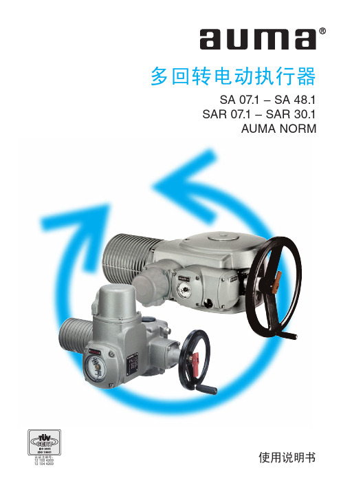
多回转电动执行器使用说明书

非侵入设置(可选)
用于 SA 07.1 – SA 16.1 型产品的限位和力矩开关的电磁感应器 MWG (仅在与执行器控制部件 AUMATIC 结合使用时) 适用于每行程 1 至 500 转或每行程 10 至 5000 转
特殊马达的连接
7.4
延迟时间
7.5
AUMA 制造的控制部件
7.6
加热器
7.7
马达保护
7.8
远程位置发送器
7.9
限位和扭矩开关
7.10
安装端子盖
8. 打开开关盒
8.1
取下开关盒护盖
8.2
取下指示器盘(可选)
9. 设置限位开关
9.1
关方向限位开关设置(黑色区域)
9.2
开方向限位开关设置(白色区域)
9.3
每个方向上采用串联开关2ncno开关之间电流隔离非侵入设置可选用于sa071sa161型产品的限位和力矩开关的电磁感应器mwg仅在与执行器控制部件aumatic结合使用时适用于每行程500转或每行程10位置反馈信号模拟可选电位计或0420ma有关更多信息参见单独的数据表扭矩反馈信号模拟可选mwg及执行器控制部件aumatic结合使用机械位置指示器不间断显示的可调节指示器盘带开和闭标记运转指示闪烁指示灯对于sa为标准配置对于sar为可选配置开关盒中的加热器标准
型号
启动次数 (百万)
基于 S4 – 25% 工作方式的每小时启动次数 (预期最短的操作寿命)
其他信息 参考文档
最小
SAR 07.1 – SAR 10.1
5.0
角行程执行器说明书

目录一、安全使用注意事项 (2)二、产品概述 (3)三、主要技术参数 (4)四、结构与原理 (5)五、安装 (10)六、调试与配线 (11)七、外形尺寸 (15)八、配套支架 (17)九、故障和解决办法 (20)十、订货说明 (20)1安全注意事项使用前请您认真阅读本说明书,并按说明书操作。
注意说明书中标有△的标志处,请务必遵守。
1.1电源与配线△接通电源之前,请确认电源电压与本执行器铭牌上注明的电源电压一致。
△电源配线应有足够的容量以满足执行器额定电流及启动电流的要求,否则,将可能引起配线烧坏造成事故。
△本执行器部位精密电子部件,请严格按照手册中接线图接线。
△请不要私自拆卸维修控制器,请与购买厂家或本公司联系。
△请安装地线并保持接地良好。
1.2 隔爆型执行器△选用隔爆型安装使用时,请严格遵守《中华人民国危险场所安全规程》中的规定:外接地牢固、良好;维修时先切断电源再打开护盖;连接电源的接线端子,爬电距离及电器间隙应大于8mm;定期检查密封圈的老化问题,如已经老化应及时更换。
更换零件须到生产厂家购买或与本公司联系,不得借用其他厂家零件;外壳应保持清洁,其最高表面温度不超过130℃。
1.3 露天安装△安装在露天中的执行器,在雨天不要开启护罩,请注意不要弄湿本执行器部或使其结霜。
△一旦部潮湿时,请切断电源,使其充分干燥后再接通电源。
△运转过程中请不要用手触摸电机表面,以免发生烫伤。
△本执行器不允许裸露运转,以防止机械卷入或发生触电危险。
△更换零件之前必须切断电源。
△发现生烟,异味或异常噪音时,请断电检查或与本公司联系。
2 产品概述2.1 概述3810R系列电子式执行器是以220V交流单相电源作为驱动电源,接收来自调节器控制信号(DC4-20mA或DC1-5V),实现预定角位移运动的新型执行器。
本系列执行器被用作调节阀的执行机构时,几乎具备了调节阀本身所要求的各种动作变换功能以及阀开度信号功能和手动功能。
IK25电动执行器说明书

IK25电动执行器说明书一、根据阀门类型选择电动执行器阀门的种类相当多,工作原理也不太一样,一般以转动阀板角度、升降阀板等方式来实现启闭控制,当与电动执行器配套时首先应根据阀门的类型选择电动执行器。
1.角行程电动执行器(转角<360度)电动执行器输出轴的转动小于一周,即小于360度,通常为90度就实现阀门的启闭过程控制。
此类电动执行器根据安装接口方式的不同又分为直连式、底座曲柄式两种。
a)直连式:是指电动执行器输出轴与阀杆直连安装的形式。
b)底座曲柄式:是指输出轴通过曲柄与阀杆连接的形式。
此类电动执行器适用于蝶阀、球阀、旋塞阀等。
2.多回转电动执行器(转角>360度)电动执行器输出轴的转动大于一周,即大于360度,一般需多圈才能实现阀门的启闭过程控制。
此类电动执行器适用于闸阀、截止阀等。
3.直行程(直线运动)电动执行器输出轴的运动为直线运动式,不是转动形式。
此类电动执行器适用于单座调节阀、双座调节阀等。
二、根据生产工艺控制要求确定电动执行器的控制模式电动执行器的控制模式一般分为开关型(开环控制)和调节型(闭环控制)两大类。
1.开关型(开环控制)开关型电动执行器一般实现对阀门的开或关控制,阀门要么处于全开位置,要么处于全关位置,此类阀门不需对介质流量进行精确控制。
特别值得一提的是开关型电动执行器因结构形式的不同还可分为分体结构和一体化结构。
选型时必需对此做出说明,不然经常会发生在现场安装时与控制系统冲突等不匹配现像。
a)分体结构(通常称为普通型):控制单元与电动执行器分离,电动执行器不能单独实现对阀门的控制,必需外加控制单元才能实现控制,一般外部采用控制器或控制柜形式进行配套。
此结构的缺点是不便于系统整体安装,增加接线及安装费用,且容易出现故障,当故障发生时不便于诊断和维修,性价比不理想。
b)一体化结构(通常称为整体型):控制单元与电动执行器封装成一体,无需外配控制单元即可现实就地操作,远程只需输出相关控制信息就可对其进行操作。
GTUT_UserManual

GT/UT ONCORE 用户手册产品介绍关于Oncore Oncore 接收器是摩托罗拉公司各类型GPS接收器的总称。
Oncore接收器通过串行口提供位置、速度、时间和卫星跟踪状态等信息。
下图为Oncore接收器的简化功能图示:图1 Oncore接收器功能方块图功能示意图介绍警告Oncore接收器有8个并行通道,可同时跟踪8颗卫星。
它通过天线接收L1 GPS信号(1575.42MHz),并对C/A码跟踪。
码跟踪由载波辅助。
Oncore接收器必须使用5V直流稳压电源。
接收器内部具有时间恢复能力,但这种功能是属于任选的。
GPS卫星发送的L1波段信号由低剖面微带插拔天线接收,经过一个窄带滤波器后,由天线模块内的信号前置放大器放大。
经过滤波放大的L1波段信号通过一根同轴电缆被送至射频信号处理电路。
该同轴电缆同时也提供天线模块进行信号前置放大所需的5V电源。
Oncore接收器印刷电路板(PCB)的射频(RF)信号处理部分包括有将天线接收的GPS信号进行下变频的电路。
最后得到的中频(IF)信号进入Oncore接收器印刷电路板上的8通道码和载波相关器,在通道分开器前高速模数转换器(A/D)已将中频信号转换为数字信号。
经过数字化处理的中频信号被送至数字信号处理器中(8通道码相关和载波相关电路也包括在其中),然后信号被分解,进入8个并行通道,以进行信号检测、码相关、载波跟踪和滤波。
经过处理的信号被同步送进定位微处理器(MPU)单元,这部分电路控制GPS接收器的工作模式和解码,处理卫星数据、测量伪距和伪距增量,以进行位置、速度和时间的计算。
另外,定位处理器单元也包括经过反相的TTL串行接口。
Oncore接收器中还有一个能使接收器保持休眠状态(keep alive)的随机存贮器(RAM),用于保存卫星星历表数据,用户操作参数,历书等信息(参见《硬件安装与数据结构》部分)。
当ONCORE接收器的电源关闭时,为防止这些信息的丢失,需外接一个+5V的备用电源。
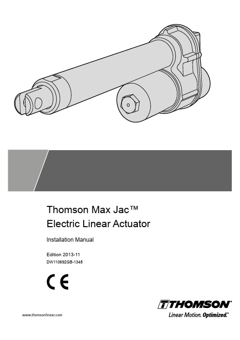
Thomson Max Jac电动直线执行器安装手册说明书

Thomson Max Jac™ Electric Linear Actuator Installation ManualEdition 2013-11DW110692GB-1348ThomsonVersion HistoryEdition Reason for revision2013-11First editionWarrantyThe Thomson Max Jack™ is warranted to be free from defects in materials and workmanship for a period of twelve (12) months from date of delivery. The application of this product is the responsibilityof the buyer and Thomson makes no representation or warranty as to the suitability of the product for any particular use or purpose. For a copy of the entire warranty for this product that is contained in our standard terms and conditions of sale, please go to /website/com/eng/support/terms_and_conditions.php.DisclaimerTechnical changes to improve the performance of the equipment may be made without prior notice! All rights reserved. No part of this work may be reproduced in any form (by printing, photocopying, microfilm or any other method) or processed, copied or distributed by electronic means without the written permission of Thomson.ContentsThomson Contents1. General (4)1.1 About this manual (4)1.2 Target group (4)1.3 Symbols used (4)1.4 Transport and storage (4)1.5 Packaging (4)1.6 Disposal (4)1.7 Support (4)2. Safety (5)2.1 Safety notes (5)3. Standards (5)3.1 EC Declaration of conformity (5)4. Installation (6)4.1 Name plate (6)4.2 Terminology (6)4.3 Operation environment (6)4.4 Mechanical installation (7)4.5 Electrical installation (8)5. Technical specifications (10)5.1 Technical data (10)5.2 Duty cycle vs. load chart (11)5.3 Type designation key (11)Thomson General 1. General1.1 About this manualThis manual decribes how to install the Thomson Max Jac™ electric linear actuator both mechanically and electrically. It also contains, among other things:• technical data• dimensional drawings• type designation key.It is important to carefully read this manual before installing the actuator and to have the correct qualifications needed to perform the installation.1.2 Target groupThis manual addresses qualified mechanical and electrical personnel.1.3 Symbols used1.4 Transport and storageThe actuator may only be transported and stored in the original packaging supplied by Thomson. The temperature during transportation and storage must be between -40 to +85 °C(-40 to +185 °F). Avoid shocks to the package. If the package is damaged, check the actuator for visible damage and notify the carrier, and if appropiate also Thomson.1.5 PackagingThe packaging consists of a cardboard box. The box contains the actuator and this manual.1.6 DisposalWhere required by law, used packaging and actuators are taken back by Thomson for professional disposal if the transportation cost is taken over by the sender. Please contact Thomson for information on where to ship it.1.7 SupportIn case you need technical support or any information related to this product, please contact the nearest Thomson Service Center. See the back of this manual. You can also visit for information on this product and how to get in touch with us.Thomson Safety and Standards2. Safety2.1 Safety notes• Only properly qualified personnel are permitted to perform mechanical and electricalinstallation on this product. Properly qualified personnel are familiar with mechanical or electrical installation work and that have the appropiate qualifications for their jobs.• Read this manual and any other available documentation before working on the equipment.that the actuator is or shall be a part of.• Keep strictly to the data in this manual and on the name plate on the actuator and neverexceeed the performance limits stated herein.• Never work on the actuator or its installation with the power on.• Never unplug any cables or connectors during operation or with power on.• Immediately stop using the actuator if it seems faulty or broken in any way and notify anappropiate person so that corrective actions can be taken.• Never try to open the actuator as that will compromise the sealing and the function of theactuator. There are no serviceable components inside.• Grease may be present on the extension tube. Contact is non-hazardous. Film should not be removed.3. Standards3.1 EC Declaration of conformityWe, Tollo Linear ABdeclare that this products corresponds with the directive 2006/42/EC annex 2.1.B, RoHS II directive 2011/65/EU, WEEE directive 2002/96/EC, low voltage directive 2006/95/EC (EN60204-1:2006+A1:2009) and also with the directive of electromagnetic compatibility 2004/108/EC (EN55014-1:2006+A1:2009, EN61000-6-3:2007, EN61000-3-2:2006+A2:2009, 61000-3-3:2008) and that the standard EN ISO 12100:2010, Safety of machinery, have been applied.Thomson Max Jac™ Linear Actuator MX12(24)xxxxxxxProduct DescriptionCan be used when the machine or the system, which it shall be, a part of is in accordance with the demands in the EEC Machinery Directive and/or other relevant regulations.Kristianstad 2013-06-19DateHåkan Persson Business Unit ManagerName Title SignatureThomson4. Installation4.1 Name plateThe name plate can be found on the actuator housing. It will tell you which model of actuator you have and its basic performance data. Please study the name plate to see what type of actuator you have before starting any installation or service on the actuator. If you need any assistance from Thomson, please tell us the manufacturing date and the deisgnation of the actuator(s) in question.4.2 Terminologya. cable outlet c. housing e. cover tube g. front adapterb. rear adapter d. motor f. extension tube4.3 Operation environmentInstallationMin. -40° C (-40° F) Max. +85° C (+185° F) IP66 / IP69KbcdfgeThomson4.4 Mechanical installationAlways install actuator so that the force of the load acts in the center of the extension tube and the rear adapter and support the mounting pins at both ends (a). Only mount the actuator to the rear and frontmounting adaptors using solid pins (b). The mounting pins must be parallel to each other both radially and axially and be supported in both ends.Failure modes of the actuator should be considered to ensure it does not create harm.Do not hold the extension tube while the tube is rotating or the unit is energized.InstallationThomsonInstallation4.5 Electrical installation4.5.1 General notes• Make sure the leads/cables leading to the motor can handle the maximum motor current.• We recommend to include an emergency stop to avoid any crushing hazard.• Never work on the actuator or the wiring with the power switched on!4.5.2 Fuse sizeProtect the actuator and the wiring by using a slow blow fuse between the actuator and the power source. See table below for recommended fuse size.4.5.3 Wire cross sectionsT o avoid malfunction due to voltage drop the cross section of the wires between the actuator motor and the power source must be of sufficient size. For longer cables than stated in the table calculations based on the supply voltage, the current draw, the length of the cables and the ambient temperature must be done.4.5.4 Connector wiring configurationsThe actuator either has flying leads or an AMP Superseal Series 1,5 connector. In case of a connector the cable leads are connected to the connector pins as shown in the diagram below.Wire cross sections Length of cable (L)Min. allowed cross section (X)00 - 10 m 1.0 mm 2 (AWG 18)10 - 20 m1.5 mm 2 (AWG 14)Actuator with analog feedback (standard)FunctionLead No.Pin. No.Potentiometer supply voltage 0 VDC 11Potentiometer supply voltage 5 VDC 22Potentiometer output signal 33Motor supply voltage 44Motor supply voltage55Actuator with digital feedback (option E)FunctionLead No.Pin. No.Encoder supply voltage 0 VDC 11Encoder supply voltage 5 VDC 22Encoder channel B output signal 33Encoder channel A output signal 44Motor supply voltage 55Motor supply voltage66* Leads for motor connections.** Leads for signal/logic connections.Recommended fuse size Actuator supply voltage Fuse size 12 VDC 10 A 24 VDC5 AThomson4.5.5 Installation of standard actuator with analog feedback 4.5.6 Installation of actuator with digital feedback (option E)By switching the polarity of the voltage to the motor the extension tube will changedirection. Make sure the switch used canhandle the maximum motor current.Warning! The actuator voltage muststroke overload to avoid causing damage to the actuator.By switching the polarity of the voltage to the motor the extension tube will changedirection. Make sure the switch used can handle the maximum motor current.Warning! The actuator voltage must stroke overload to avoid causing damage to the actuator.Installation M Actuator motorS1 Double pole double throw (DPDT) switch F FuseE Digital feedback deviceM Actuator motorS1 Double pole double throw (DPDT) switch F FuseP Analog feedback device+–+Thomson5. Technical Specifications5.1 Technical data(1) Specifications are subject to change without notice. It is the responsibility of the product user to determine the suitability of this product for a specific application.(2) The static force (i.e. the backdriving force) for a ball screw unit varies and is dependant on the number of cycles it have been running and at wich loads.(3) Strokes possible for ball screw models only.(4) For ball screw actuator with 100 mm stroke, average load of 500 N and changing load direction.ThomsonThomson Max Jac™ Electric Linear Actuator - Installation Manual - 2013-11115.2 Duty cycle vs. load chart5.3Ordering KeyDynamic load [N] (lbs)ED @ 25 °C [%]040802060100600(155.0)700(167.5)800(180.0)100(22.5)200(45.0)300(67.5)400(90.0)500(112.5)DW110692-GB-1348 ENGSpecifications are subject to change without notice. It is the responsibility of the product user to determine the suitability of this product for a specific application. All trademarks property of their respective owners. © Thomson 2013. EUROPEUnited KingdomThomsonPhone: +44 (0) 1271 334 500Fax: +44 (0) 1271 334 501E-mail:**************************GermanyThomsonNürtinger Straße 7072649 WolfschlugenPhone: +49 (0) 7022 504 0Fax: +49 (0) 7022 504 405E-mail:*******************************FranceThomsonPhone: +33 (0) 243 50 03 30Fax: +33 (0) 243 50 03 39E-mail:******************************ItalyThomsonLargo Brughetti20030 Bovisio MasciagoPhone: +39 0362 594260Fax: +39 0362 594263E-mail:*********************SpainThomsonRbla Badal, 29-31 7th, 1st08014 BarcelonaPhone: +34 (0) 9329 80278Fax: + 34 (0) 9329 80278E-mail:***************************SwedenThomsonEstridsväg 1029109 KristianstadPhone: +46 (0) 44 24 67 00Fax: +46 (0) 44 24 40 85E-mail:***********************************SOUTH AMERICAThomsonSao Paulo, SP BrasilPhone: +55 11 3879 6600Fax: +55 11 3879 6656Email:******************************USA, CANADA and MEXICOThomson203A West Rock RoadRadford, VA 24141, USAPhone: 1-540-633-3549Fax: 1-540-633-0294E-mail:*************************Literature: ASIAAsia PacificThomson750, Oasis, Chai Chee Road,#03-20, Technopark @ Chai Chee,Singapore 469000E-mail:****************************ChinaThomsonRm 2205, Scitech Tower22 Jianguomen Wai StreetBeijing 100004Phone: +86 400 6661 802Fax: +86 10 6515 0263E-mail:*****************************IndiaThomson India1001, Sigma BuildingHiranandani Business ParkPowai , Mumbai – 400076Phone. +91 22 422 70 300Fax: +91 22 422 70 338E-mail:*****************************JapanThomsonOsaka 564-0044Phone: +81-6-6386-8001Fax: +81-6-6386-5022KoreaThomsonF12 Ilsong Bldg, 157-37Seoul (135-090)Phone: +82 2 6917 5049Fax: +82 2 6917 5007E-mail:*****************************。
美国奥玛电动门调试说明二.
美国奥玛电动门调试说明二9.电气定位板(选项)9.1 技术数据9.2 设定AUMA MA TIC中的定位板是根据用户要求在发运前被事先设定。
由于控制系的特性不可能与预计的完全吻合,所以必须再次调整。
调整前要对定位板的编程进行检查。
* 松开AUMA MATIC盖上的4只螺栓,并取下外盖。
* 按照15.2项逻辑板的编程。
当使用定位板时远程控制自保持必须处于关断状态。
* 取下盖板(图S2)并根据需要参数表4在定位板图(S1)上编程控制信号E1和反馈信号E2的数值见盖板(图S2)上的标识。
控制信号E1和反馈信号E2失去时执行器的状态可以通过位置板上的拨码开关实现。
此功能仅对4-20mA信号时适用。
* 调试之前必须确认位置反馈回路E2闭合(测试仪器或跳线)。
否则,失去信号E2诊断灯LEDV10“E1/E2<4mA 亮起,并且位置反馈没有响应。
表4 推荐设定表5;其它设定1)内部反馈信号;有电子位置变送器给出的0/4—20mA或由5000欧姆精确电位计给定0—5V信号2)因为E1或E2信号〈4mA时仍会工作(关端点信号=0V或0mA),所以当E1或E2信号丢失时回引起误解。
3)当配有外部模拟/脉冲信号转换(选项);在两个方向上附加紧急操作信号。
(第15.3项)4)仅适用于活零信号(即4—20mA)9.3全关位置定位板的调节(标准)调整定位板之前,确保执行器的限位开关和力矩开关以及位置反馈),已经设定完成。
* 把选位开关旋转到现场控制(LOCAL)。
* 用按扭操作执行器到全关位置。
* 输入控制信号E1=0或4mA(见接线图)。
* 逆时针旋转电位计P10(t)至不动为止。
(Figure S2)E1/E2信号断掉或极性错误指示灯LED V10 E1/E2<4mA会显示出来。
(图S2)* 用电压表测量MP3和MP4( Figure S3),检查输入信号电压值(0-5V)。
控制信号E1为0mA时测量指示为0V。
GT协议转换器E1-V24说明书
(F)E1/V.24接口转换器用户手册安全使用须知(F)E1/V.24接口转换器在设计使用范围内具有良好可靠的性能,但仍应避免人为对设备造成的损害或破坏。
◆仔细阅读本手册,并保存好本手册,以备将来参考用;◆不要将设备放置在接近水源或潮湿的地方;◆不要在电源电缆上放任何东西,不要将电缆打结或包住,并应将其放在不易碰到的地方;◆电源接头以及其它设备连接件应互相连接牢固,请经常检查;◆连接电源线时,务必认真按接线柱标注接线;所用电源必须满足如下条件:1.直流-48V机种:-36V ~-72V2.交流220V机种:220V±20%,50Hz◆请注意设备清洁,必要时可用软棉布擦拭;◆不要堵塞通风口;◆在下列情况下,请立即断开电源,并与公司联系:1.设备进水;2.设备摔坏或机壳破裂;3.设备工作异常或展示的性能已完全改变;4.设备产生气味、烟雾或噪音。
◆请不要自己修理设备,除手册中有明确指示外。
一、概述(F)E1/V.24接口转换器是北京佳特科为科技有限公司()使用自主开发的专用集成电路研制生产的E1到V.24 接口转换器。
该设备是以超大规模集成电路为核心构成的E1 到V.24接口转换设备,适用于基于V.24接口的数据网。
(F)E1/V.24接口转换器还可提供集中式机框结构。
二、主要特点◆提供1路透明或成帧V.24接口;◆提供1个E1数字口,阻抗75Ω/120Ω;◆提供多个功能开关,适应不同的应用需求;◆采用大规模芯片,电路简单,功耗低,可靠性高;◆体积小,重量轻,工作稳定可靠,安装方便;◆适应多种电源环境。
三、设备原理说明V.24接口的数据信号送入转换器,由专用集成芯片提取时钟,对信号译码并映射到E1信号的码流中。
接收侧E1信号送到专用集成芯片中进行时钟提取和解码,恢复成原有V.24信号,经输出驱动电路送出符合V.24接口要求的信号。
图3.1 原理框图四、产品安装4.1 设备拆封1.在您确定了设备的安装位置后,清理好该处,并将装有设备的纸箱移到安装处旁; 2. 请注意包装箱方向,保证正面朝上; 3.打开纸箱,取出设备及附件。
GT-Power中文使用手册
用户手册
华中科技大学பைடு நூலகம்振动、噪声与诊断研究所
PDF 文件使用 "pdfFactory Pro" 试用版本创建
目录
第一章 消声器设计前处理 ......................................................................................1 第一节 图形用户界面(GUI).........................................................................1 1.1.1 打开一个新文件 ................................................................................1 1.1.2 截面库................................................................................................2 1.1.3 输入外部形状文件.............................................................................2 1.1.4 绘图区域 ............................................................................................4 1.1.5 树状图................................................................................................5 1.1.6 工具条和菜单项 ................................................................................5 第二节 工具条和下拉菜单 ...............................................................................5 1.2.1 工具条.................................................................................................5 1.2.2 菜单特征 ............................................................................................7 第三节 创建和编辑对象 ...................................................................................9 1.3.1 消声器壳体 ........................................................................................9 1.3.2 隔板..................................................................................................10 1.3.3 隔板开孔 ..........................................................................................11 1.3.4 隔板打孔 ..........................................................................................11 1.3.5 直管..................................................................................................12 1.3.6 分支连接...........................................................................................12 1.3.7 弯管..................................................................................................13 1.3.8 交叠管..............................................................................................14 1.3.9 同心管(套管) ..............................................................................15 1.3.10 管口................................................................................................15 1.3.11 管上打孔 ........................................................................................15 1.3.12 绒毛................................................................................................16 第四节 三维显示窗口 .....................................................................................16 第五节 输入消声器组件到 GT-POWER .........................................................17 1.5.1 干扰..................................................................................................18 1.5.2 离散消声器 ......................................................................................18 1.5.3 在 GT-POWER 仿真时使用多个消声器..........................................19 1.5.4 在 GT-POWER 仿真时使用双排气系统...........................................19
FS-GT3C说明书
2.SERVICES (2)...................................................3.THE SPECIAL SYMBOLS (3)................................................4.SAFTY GUIDES.. (3).................................................6.BATTERY CHARGING NOTES.. (5)7.TANSMITTER PARAMETERS (6).............................................8.RECEIVER PARAMETERS.. (6)..............................................9.RECEIVER CONNECTIVITY.............................7.............................................11.EACH PART OF THE TRANSMITTER..................11........................................13.TRANSMITTER FUNCTION NOTES (22)15.SIMULATE (25)...................................................16.PACKAGING WITH CONTENT LIST. (26).........................................524GHZ SYSTEM 4.. ........................................................................................12.LCD FUNCTION EXPLANATION 13 .............................................................14.FAIL SAFE FUNCTION (24)6.01 TRANSMITTER CHARGER (5)6.02 RECEIVER CHARGER (5)9.01 INSTALLATION WHEN A MOTOR CONTROLLER IS USED (7)9.02 INSTALLATION FOR GAS POWERED MODELS (8)10.01 MATCHING (CODE )........................................................................9 10.02 POWER.ON...................................................................................10 10.03 SHUT.DOWN.................................................................................1012.01 LCD DISPLAY................................................................................13 12.02 OPENING SCREEN........................................................................13 12.03 MODEL.........................................................................................14 12.04 NAME............................................................................................15 12.05 REV..............................................................................................16 12.06 E.POINT........................................................................................17 12.07 TRIM.............................................................................................18 12.08 D /R..............................................................................................19 12.09 EXP..............................................................................................20 12.10 ABS...............................................................................................21 13.01 STEERING CONTROL. (22)13.02 THROTTLE CONTROL (23)6.BA TTERY CHARGING NO TES6.BA TTERY CHARGING NO TESFS-GT3C7.TRANSMITTER PARAM E TERS8.RECEIVER PARAM E TERSno more3.7USB328151*138*1161.通道个数:3个通道;3.发射功率:小于等于20bBm(100mW);7.低电压报警功能:有(低于3.7伏后);6.数据分辨率:1024级;8.数据输出接口:有(3.5英寸);9.充电接口:有(USB);10.电源标准:3.7V(800毫安锂电);12.天线长度:26毫米;13.外形尺寸:151*138*116毫米;15.安规认证:CE、FCC;2.适合机种:车、船;4.调制方式:GFSK;5.系统模式:AFHDS;11.整机重量:328克;14.外观颜色:黑色;20dBm(100mW);B9.RECEIVER CONNECTIVITY 9.01INSTALLATION WHEN A MOTOR CONTROLLER IS USED:9.02INSTALLATION FOR GAS POWERED MODELS:10.2.4G OPERA TION NO TES 10.01MATCHING(CODE)10.02POWER ON:10.03SHUT DOWN:12354678A11.EACH PART OF THE TRANSMITTERCDE F G I HJBA12.02OPENING SCREEN :12.01LCD DISPLAYBUTTON FUNCTION :按键定义:12.L CD FUNCTION EXPL ANA TION3.7V3.7V12.03MODEL:CC12.04NAME:Function explanation :Operation :12.05 REV :CHANNEL:12.06 E .POINT :olnCHANNEL:%CHANNEL:%功能说明:此功能是对三个输出通道中立点微调的设定,调整修正机种在装配及伺服系统中心点不以使车或船等模型在操控时更加直线。
