6660产品说明 3HAC028207-001_revF_en
SH366000 Introduction V0.0

Preliminary SH366000入门指南1V 0.0本文档主要针对在SH366000市场推广中所遇到的问题进行总结,并按照系统信息、常用配置、常见问题进行分类。
一、SH366000系统信息..............................................................................................................................................................31.1SH366000可以兼容哪些机型,有没有兼容性问题......................................................................................................31.2SH366000具有哪些工作模式,功耗如何......................................................................................................................31.3SH366000电流、电压、温度精度如何..........................................................................................................................31.4SH366000容量采用哪种算法,精度如何......................................................................................................................31.5SH366000具有哪些保护功能..........................................................................................................................................31.6SH366000器件选择有哪些特别的注意事项..................................................................................................................41.7SH366000采用什么振荡器,精度如何..........................................................................................................................41.8SH366000 PCB Layout 有哪些特别的注意事项..............................................................................................................4二、SH366000常用配置.. (5)2.1如何选择2-,3-,4-设置,应更改哪些参数.................................................................................................................52.2如何更改器件名称、厂商名称、SMBus 版本号等信息................................................................................................52.3如果不需要预充电模式,应该如何配置.......................................................................................................................52.4如果不需要PRES 存在的低功耗模式,应该如何配置..................................................................................................52.5如果不需要二级保护,应该如何配置...........................................................................................................................62.6如何设置动态EDV ,如何设置固定EDV0......................................................................................................................62.7如何设置在充满、放空时不关闭相应的充电、放电MOSFET (6)2.8SH366000电流取样电阻选用多大阻值..........................................................................................................................72.9SH366000如何设置LED 显示...........................................................................................................................................72.10SH366000如何开启中间校准..........................................................................................................................................72.11SH366000如何开启对外广播..........................................................................................................................................72.12SH366000充电截止条件有哪些 (7)SH366000 入门指南2V0.02.13SH366000放电截止条件有哪些......................................................................................................................................82.14SH366000预充电模式的进入退出条件是什么..............................................................................................................82.15SH366000如何更新FCC 、MaxError..............................................................................................................................8三、SH366000常见问题 (9)3.1 SH366000上电后没有电压,没有通讯,怎么处理.......................................................................................................93.2SH366000激活后有SMBus 通讯,但无法进行充放电,怎么处理...............................................................................93.3SH366000能够放电,但不能充电,怎么处理..............................................................................................................93.4SH366000放电正常,充电也正常,可是充不满,怎么处理....................................................................................103.5SH366000能够充电,但不能放电,怎么处理............................................................................................................103.6SH366000学习后MaxError 未更新,或不是2%,怎么处理.......................................................................................103.7SH366000电压、电流、温度精度特别差,怎么处理................................................................................................103.8SH366000温度为116.9度,电压为0,电流为-16384mA ,怎么处理.........................................................................113.9SH366000出现温度为116.9或-112度,怎么处理........................................................................................................113.10SH366000温度校准无效,怎么处理............................................................................................................................113.11SH366000电压无法校准,怎么处理............................................................................................................................113.12SH366000电流校准无效,怎么处理............................................................................................................................113.13SH366000老化结束时,无法进行补电,怎么处理....................................................................................................11四、历史版本 (12)SH366000 入门指南3V0.0一、SH366000系统信息该部分主要为SH366000系统简介,关注点一般集中在对外接口、关键功能、性能指标等方面。
IND360产品系列的商品说明书

IND360base Automation Indicators• CalFree TM and CalFree Plus TM, as well as automaticPLC/DCS-driven calibration of precision scalesI N D 360b a s e A u t o m a t i o n I n d i c a t o rTechnical FeaturesIND360 Automation Indicator Technical Features Continued IND360 Automation IndicatorParameter Detail Units ofMeasurementDINPanelHarshHousingEnclosure typeDIN-Rail mount,quick connection with automatic grounding Panel mount with detachable electronicsVESA 100 Desk/wall/column mountMaterialRugged ABS plasticStainless steel front panel with hygienic drip edge including mounting hardware Stainless steel, includes fixed-angle brackets Ingress protection IP20, Type 1IP65 display, IP20 electronicsIP66 and IP69KW × H × D mm / in 40 × 130 × 100 / 1.6 × 5.1 × 3.9175 × 94 × 16 / 6.9 × 3.7 × 0.6275 × 85 × 200 / 10.8 × 3.3 × 7.9Shipping weight kg / lb 0.5 / 1.11.7 / 3.73.6 / 7.9Legal for Trade °C / °F -10 to 40 / 14 to 104; 10% to 90% relative humidity, non-condensing Operation °C / °F -10 to 50 / 14 to 122; 10% to 90% relative humidity, non-condensing Storage°C / °F -40 to 60 / -40 to 140; 10% to 90% relative humidity, non-condensing PowerRequirementsDC poweredVDC / W20 - 28VDC 1 / 12W 21 Power supply short circuit protection time shall be equal or longer than 100ms.218W, when 5 to 8 POWERCELLs are connectedAC poweredVAC / Hz NA 100 - 240 VAC / 49 - 61 Hz Power Dissipation DC powered W 3 4.5 4.5AC powered WNA 66ScaleNumber of scales 1Strain gauge (analog) type Max. 8× 350Ω (20× 1,000Ω) load cells; 1-4mV/V sensitivity; 5VDC excitation voltageμV buildrecommended / approved 0.1 μV/d recommended; 0.3 μV/e Weights and Measures approvedPOWERCELL ® type Supports one PowerDeck TM floor scale or a network of up to 8 POWERCELL ® load cells, or PowerMount TM weigh modulesPrecision type Precision scales and weigh modules – see Precision Scale Compatibility on page 6Adjustment / calibration Zero / span with linearization up to 5 points; step; CalFree (analog scale) / CalFree Plus (POWERCELL ® scale)Primary unit Analog/POWERCELL ®: g, kg, lb, t and tonPrecision: Determined by scale or weigh module Calibration unit Analog/POWERCELL ®: g, kg, lb, t and ton Precision: Determined by scale or sensorCapacity & incrementAnalog/POWERCELL ®: 1,000,000 maximum Capacity, maximum 100,000 display incrementsPrecision: Determined by scale or sensorConnectivityAutomation interface Optional: EtherNet/IP , Profibus DP , PROFINET, EtherCAT, CC-Link IE Field Basic, Mod-bus TCP , Modbus RTU, or Analog Output (4-20 mA/0-10VDC, 16-bit resolution)Redundancy Media Redundancy Protocol (MRP - Siemens) and Device Level Ring (DLR - ODVA)Protocol Standard Automation Interface (SAI) 2 and 8 block format Protocol type Floating point and binary; cyclical or acyclicalSimultaneous floating point variables 1 or 7 user-selectable including status block for condition monitoringAlarm status Smart5TMbased on NAMUR NE107Condition monitoring Heartbeat, Data OK, Smart5TMAutomation Bus driv-ers - Siemens GSD (Profibus DP), GSDML (PROFINET), function block Certification Profibus DP / PROFINETProfibus international Certificate No: Z02266, Z13050, Z13051Parameter DetailUnits of Mea-surementDINPanelHarshConnectivityAutomation device drivers ODVA / Rockwell Electronic Data Sheet (EDS), Custom Add-on Profile (AOP), Custom Add-on Instruction (AOI)Certification EtherNet/IP Open Device Vendors Association (ODVA) File Number: 12095.01Automation Bus drivers - BeckhoffEtherCAT Slave Information (ESI)Automation Bus drivers - MitsubishiControl & Communication System Profile Plus (CSP+)Certification CC-Link IE Field BasicCC-Link Partner Association (CLPA) Reference Number: NTC-SL-00032, NTC-IFB-00036Service Interfaces Service interfaces Web interface over Ethernet TCP/IP and/or keypad and displayService functions Configuration, adjustment, parameter backup and restore, cloning and monitoring Automation Bus Update RateStrain gauge (analog)Hz960 for PROFINET, EtherNet/IP , Profibus DP , EtherCAT, CC-Link IE Field Basic without application480 for PROFINET, EtherNet/IP , Profibus DP , EtherCAT, CC-Link IE Field Basic with application100 for analog output, Modbus TCP and Modbus RTUPOWERCELL ®/PowerMount TM / PowerDeck-TM100 for 1-4 load cells; 50 for 5-8 load cells over all automation interfacesPrecisionMaximum 92Hz over all automation interfaces FilteringStrain gauge (analog)Weighing Mode Normal, dynamicEnvironment Very stable, stable, standard, unstable, very unstable Limit FrequencyLow pass filter, 1 - 20Hz POWERCELL ®/ PowerMount/PowerDeckLow Pass Filter Very light, light, medium, heavy Stability FilterEnable, disablePrecision scales and weigh modulesFilter type and settings depending on scale or weigh module Inputs / OutputsOptional inputs (selectable polarity)Max. 5 inputs - functions: none, clear tare, tare, zero, print. Voltage range high: 5 ~ 30VDC; voltage range low 0 ~ 3VDCOptional OutputsMax. 8 outputs - functions: none, center of zero, comparators (1-8), Smart5 red, Smart5 orange, motion, net, over capacity, under zero. Voltage range high: 5 ~ 30VDC, max current 150mA Display Type1.04“ Green OLED4.3” Color TFTOn-display status IndicatorsWeight units, gross/net indication; graphic symbols for motion, center of zero, Smart5 alarms.Tri-color status LEDs System (SYS), Network 1 (NW1), Network 2 (NW2)Status information displayed on main display Weight displayCharactersMaximum 9 digits including sign, displays 8 weight digits on high-precision devices Keyboard Keys 4 keys (Up, Down, Left, Enter)5 keys (Up, Down, Left, Right, Enter)Overlay0.9 mm thick polyester overlay (PET) with 0.178 mm thick polycarbonate display lens0.9 mm thick polyester overlay (PET) with 0.178 mm thick polycarbonate display lens User Security - 3 levels: administrator, maintenance and operator LogsAlibi 27,000 records Error log 500 recordsMaintenance log2,500 recordsChange log 2,500 recordsIII III N D 360b a s e A u t o m a t i o n I n d i c a t o rTechnical Features ContinuedIND360 Harsh dimensionIND360 DIN dimension175mm94 mm114 m m 275 m m87 mm200 mm 135 mm40 mm100mmActuatorsPLC/DCSPrecision Scale Compatibility IND360 Automation IndicatorsIND360 Precision connects to many types of precision weigh modules. The following table lists how various functions are supported when different types of weigh modules or scales are connected.Precision Scales for Legal-for-TradePrecision Scales for AutomationCompatible Modules PBD555 / PBD769 / PBD655 / PBK785 / PBK9 / PTA4XX / PFA5XX / PUA5XX / PFA779lift / PFK9WKC / WMS / WXS / SLF6 / PBK989-APW / PFK989-APW Basic Functions:Read weight and status, tare, zero, clearDisplay/keypad Display/keypad Web interface Web interface Automation interfaceAutomation interfaceParameter configuration:e.g. calibration, adjustment, filter parametersPanel and harsh version: use the display/keypadDIN version: not supported on OLED. Use panel display(30617718), and the display cable (30624029). Purchase as a separate item.Display/keypad (main parameters)Software tool: APW-Link (all parameters)Automation interface 1Firmware upgrade for pre-cision modulesSoftware tool: eloaderSoftware tool: eloader1Each weigh module supports different functions. Please consult the SAI (Standard Automation Interface) manual for further details.Safety and Metrology ApprovalSafety and MetrologyI N D 360b a s e A u t o m a t i o n I n d i c a t o rOrdering InformationIND360 Automation Indicators IND360 is available in different variants with the main item number 30601194.Choose options according to the variant configuration structure, and contact your METTLER TOLEDO Sales represen-tative for detailed ordering information.C - 5in8out (Solid State)Modbus TCP or EtherCAT or CC-Link IE Field Basic)M - Modbus RTU R - Profibus DPOrdering InformationIND360 Automation IndicatorsBase Unit DescriptionsItem Number IND360 in different enclosures 30601194IND360 DIN Mount IND360 Panel Mount IND360 HarshSmart Options1 = None (analog scale)4 = Precision (PBK, PFK) - Standard Industrial (approved readability and M12 connector on terminal side)5 = PowerDeck M12 (connector on terminal side)6 = PowerMount (open wires on terminal side)8 = Precision - APW incl. PBK, PFK (higher readability and open wires on terminal side)Input/Output Options0 = NoneA = Analog output (4 - 20mA / 0 - 10VDC)B = Analog output (4 - 20mA / 0 - 10VDC) plus 3 digital inputs / 4 digital outputs (solid state)C = 5 digital inputs / 8 digital outputs (solid state)Connectivity Options 0 = NoneI = Industrial Ethernet (PROFINET or EtherNet/IP or Modbus TCP or EtherCAT or CC-Link IE Field Basic)M = Modbus RTU R = Profibus DPApplication Options 0 = Base F = Fill/dose T = Tank vesselL = legacy IND131/331 PLC CommunicationPower Options1 = AC (AC/DC power module included)3 = DCFor more information/IND360METTLER TOLEDO Group Industrial DivisionLocal contact: /contactsSubject to technical changes©06/2022 METTLER TOLEDO. All rights reserved Document No. 30531752 B MarCom IndustrialOrdering InformationIND360 Automation IndicatorsAccessoriesItem Number Descriptions30601149 4 - 20mA / 0 - 10VDC analog output PCBA kit for IND360 DIN and Panel mount version including enclosure opening tool 30601150 4 - 20mA / 0 - 10VDC analog output PCBA kit for IND360 Harsh version30601151PCBA kit of 4 - 20mA / 0 - 10VDC analog output, 3 discrete inputs, 4 discrete outputs (solid state) for IND360 DIN and Panel mount version including enclosure opening tool30601152PCBA kit of 4 - 20mA / 0 - 10VDCA analog output, 3 discrete inputs, 4 discrete outputs (solid state) for IND360 Harsh version 30601153PCBA kit of 5 discrete inputs, 8 discrete outputs (solid state) for IND360 DIN and Panel mount version including enclosure ope-ning tool30601154PCBA kit of 5 discrete inputs, 8 discrete outputs (solid state) for IND360 Harsh version30601155PCBA kit of Industrial Ethernet connection (PROFINET, EtherNet/IP , EtherCAT, CC-Link IE Field Basic or Modbus TCP) for IND360 DIN and Panel mount version including enclosure opening tool30601156PCBA kit of Industrial Ethernet connection (PROFINET, EtherNet/IP , EtherCAT, CC-Link IE Field Basic or Modbus TCP) for IND360 Harsh version30601159PCBA kit of Modbus RTU connection for IND360 DIN and Panel mount version including enclosure opening tool 30601160PCBA kit of Modbus RTU connection for IND360 Harsh version30601161PCBA kit of Profibus DP connection for IND360 DIN and Panel mount version including enclosure opening tool 30601162PCBA kit of Profibus DP connection for IND360 Harsh version 30617714AC/DC Power Module APS32430617716Power supply cable from the APS324 power module to IND36030624028Complete set of IND360 connecters.30624029Display cable (3m) from IND360 module to the panel. Use this when the IND360 module is not mounted to the back of the panel.30624030Display cable (11cm) from IND360 module to the panel. Use this when the IND360 module is mounted to the back of the panel.30462051VESA 100 Bracket to mount a IND360 Harsh version on desk or on wall 22020286Adjustable Column Bracket VESA 100 for IND360 Harsh version 30624077Opening tool for IND360 DIN mount version enclosureI N D 360b a s e A u t o m a t i o n I n d i c a t o r。
USB-7660 系列硬件 说明书
硬件说明书USB-7660USB-7660 系列硬件说明书声明:本手册的版权归本公司所有,并保留所有的权利。
本公司的权利,恕不另行通知。
本手册的任何一部 分未经过本公司明确的书面授权,任何其他公司或个人均不允许以商业获利目的来复制、抄袭、翻译或者 传播本手册。
订购产品前,请向本公司详细了解产品性能是否符合您的要求。
产品并不完全具备本手册的 所描述的功能,客户可根据需要增加产品的功能,具体情况请跟本公司的技术员或业务员联系。
本手册提 供的资料力求准确和可靠。
然而,本公司对侵权使用本手册而造成后果不承担任何法律责任。
安全使用常识:• 使用前,请务必仔细阅读产品用户手册。
• 当需要对产品进行操作时请先关闭电源。
• 不要带电插拔,以免部分敏感元件被瞬间冲击电压烧毁。
• 避免频繁开机对产品造成不必要的损坏。
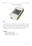
第 1 页 共 27 页硬件说明书USB-7660目录第一章 产品介绍………………………………………………………………………………………………3 1.1 概述 …… ……………………………………………………………………………………………3 1.1.1 USB/RS485/RS232多方式通讯接口……………………………………………………41.1.2 自动通道/程控增益………………………………………………………………….…………………4 1.1.3 模块上48路(单)/24路(差分)模拟输入……………………………………………………………4 1.1.4 模块上4路模拟输出………………………………………………………………….…………………4 1.1.5 模块上可编程的3路计数器………………………………………………………………….……………4 1.1.6 模块上16路数字输入和16路数字输出………………………………………………………………….4 1.1.7 系统开机时模拟输出设置和输出值………………………………………………………………….…4 1.1.8 重新启动数字量保持输出值………………………………………………………………….…………4 1.2 特点………………………………………………………………….…………………4 1.3 一般特性………………………………………………………………….…………………5第二章 安装与测试………………………………………………………………….…………………………52.1 初始检查………………………………………………………………….…………………5 2.2 跳线分布图………………………………………………………………………….…………………5 2.3 跳线设置………………………………………………………………………….…………………5 2.3.1 模拟输入量程跳线说明 --JP1………………………………………………………………………….5 2.3.2 模拟输入单端/差分方式跳线说明 --JP2………………………………………………………………5 2.3.3 模拟输入电压/电流方式跳线说明 -JP3~JP34、 JP42~JP57…………………………………………6 2.3.4 供电方式路线说明………………………………………………………………………….……………6 2.3.5 模拟输出跳线说明………………………………………………………………………….……………6 2.3.6 上电模拟输出跳线说明………………………………………………………………………….………6 2.3.7 终端匹配电阻路线说明………………………………………………………………………….………6 2.4 Windows2K/XP/9X下板卡的安装………………………………………………………………………….…7 2.4.1 软件的安装………………………………………………………………………….…………………7 2.4.2 硬件的安装………………………………………………………………………….…………………9 2.5 测试………………………………………………………………………….…………………9 2.5.1 模拟输入功能测试………………………………………………………………………….……………9 2.5.2 模拟输出功能测试………………………………………………………………………….……………10 2.5.3 计数器输入功能测试………………………………………………………………………….…………10 2.5.4 频率输入功能测试………………………………………………………………………….……………11 2.5.5 数字量输入功能测试………………………………………………………………………….…………11 2.5.6 数字量输出功能测试………………………………………………………………………….…………12 2.5.7 232通讯功能测试………………………………………………………………………….……………13 2.5.8 485通讯功能测试………………………………………………………………………….……………17第三章 连接说明………………………………………………………………………….…………………173.1 管脚和电位器分布图………………………………………………………………………….……………17 3.1.1 管脚功能定义说明………………………………………………………………………….……………17 3.1.2 电位器功能说明………………………………………………………………………….………………18 3.2 模拟输入连接………………………………………………………………………….………………18 3.2.1 单端模拟输入连接及注意事项………………………………………………………………………….19 3.2.2 差分模拟输入连接及注意事项………………………………………………………………………….19 3.3 模拟输连接………………………………………………………………………….…………………19 3.3.1 电压模拟输出连接………………………………………………………………………….……………19第 2 页 共 27 页硬件说明书USB-76603.3.2 电流模拟输出连接………………………………………………………………………….……………19 3.4 计数器/频率输入连接………………………………………………………………………….…………20 3.5 数字量输入连接………………………………………………………………………….…………………20 3.5.1 TTL数字信号输入连接及注意事项………………………………………………………………………20 3.5.2 光隔数字信号输入连接及注意事项……………………………………………………………………20 3.6 数字量输出连接………………………………………………………………………….…………………21 3.6.1 TTL数字信号输出连接………………………………………………………………………….…………21 3.6.2 光隔数字信号输出连接………………………………………………………………………….………21第四章 结构说明………………………………………………………………………….…………………21 第五章 常见问题及解决方法…………………………………………………………………….………23第一章 产品介绍1.1 概述 USB-7660/7660D/7660A/7660AD/7660B/7660BD/7660N/7660DN/7660AN/7660B/7660ADN/7660BDN/7660 DA/7660DAN 系列既是真正即插即用 USB 的数据采集模块,也是 RS485/232 通讯方式的数据采集模块,因此 无需再打开您的计算机机箱来安装板卡,仅需插上模块,便可以采集到数据。
MT6620 datasheet

Copyright © MediaTek Inc. All rights reserved.
2012/1/20
1
Internal Use
Outline
▪ Module features overview ▪ Module block diagram and interface ▪ Module pin description and reference design ▪ MT6620 ATE test instrument support ▪ PCB /Antenna layout guide. ▪ Apply for WiFi MAC address numbers
WiFi self-calibration function embedded Supported WiFi 11b/g /n features Supported WiFi SDIO 2.0 (4-bits and 1-bit up to 50MHz) Bluetooth specification 3.0+HS (802.11 AMP) compliance (W1126 ready) Supported Bluetooth 4.0, BT Low Energy (LE) GPS/GALILEO/QZSS/SBAS(WAAS/MSAS/EGNOS/GAGAN) support Best GPS sensitivity : -165 dBm tracking sensitivity, -160 hot start sensitivity. Supported FM 76-108MHz band with 50KHz step. Supported FM RDS/RBDS
GPS_ANT_P GPS input port EEDI
Conettix IP设备说明书

Typical Application
Control Panel
Host PC with D6200 Software
Why is Conettix IP better?
• Compatible with almost all manufacturers’ control panels — simple integration into an existing system
Receiver/Gateway
panel LCD display for programming, status and event information. Caller ID, ANI and DNIS compatible. PC-based platform design for future expandability.
D6690 SAFECOM Line Card
Adds SAFECOM Long-Range Radio capability that supports up to 2500 SAFECOM Radios. Supports up to 4 RF-2000 Radio Modems per line card and an additional 4 with the installation of a D6691 SAFECOM Expansion Card. Requires 1 D6695 SAFECOM Termination Card per D6690.
• supports both Static IP and Dynamic IP addressing using DHCP.
• UDP/IP packets average 64 bytes, which consume minimal bandwidth
Power Focus 6000产品说明书

Why a smartfactory?Because this is the future.In the smart factory, state-of-the-artsoftware provides real-time data fromconnected devices enabling them tolearn and adapt to changing demandson the production lines.The technology contributes tomanaging the entire productionprocess and enables continuousimprovements in productivity andend-product quality.How Atlas Copco cantake you one step closerAtlas Copco has the technology to solve yourproduction challenges. Technology that can operateseveral tools using only one physical controller, predicttool failures, and suggest maintenance schedules.Technology that gives valuable insights into the data it generates from previous production programs. The data continuously created by Atlas Copco smart tools and solutions can be used to maximize uptime and quality in your operation and cut yourWe present our Power Focus Offering. It's smart!What do you need in order to create a smart assembly?Power up your tightening stationsTurboTight for STR tools and TensorPulse and TurboTight for SRB tools help minimize Improves ergonomics by eliminating reaction force; increased productivity due to faster tightening time TBP SRB ST WrenchTensor STRQST Tensor SLMWR-TA MWR-STensor STB Tensor ES Tensor SBTBP-S BCP-REIAM Power Focus Power Focus 6000Fieldbus modulesController accessoriesElectronic deliveryPhysical deliveryItemOrder nr.Hardware Power Focus 60008436 1800 02Power Focus 6000 LV8436 1800 11ItemOrder nr.Profibus 8436 0940 05DeviceNet8436 0940 10Ethernet/IP 2 PORT 8436 0940 15ProfiNet I/O 2 PORT 8436 0940 20Anybus CC – CC Link 8436 0940 25Anybus CC – CC Link IE8436 0940 30Open Protocol Extension Open Protocol Extension 1 pcs 8436 1950 20TrueAngle TrueAngle 1 pcs8436 1910 03StepSync StepSync 1 pcs8436 1950 00Industrial Location Guidance Industrial Location Guidance 1 pcs8436 1950 10 SoftPLC SoftPLC 1 pcs 8436 1910 04Yield Control Yield Control 1 pcs8436 1910 06ItemOrder nr.Low Reaction Strategies Low Reaction Strategies 1 pcs 8436 1910 80Electronic deliveryJoint ControlJoint Control Virtual Station 1 pcs 8436 1960 20Station ControlStation Control Virtual Station 1 pcs 8436 1960 30Critical ControlCritical Control Virtual Station 1 pcs 8436 1960 40Process ControlProcess Control Virtual Station 1 pcs8436 1960 50ItemOrder nr.Batch ControlBatch Control Virtual Station 1 pcs 8436 1960 10Physical deliveryItemOrder nr.Batch ControlBatch Control Virtual Stations 1 pcs 8436 1960 11Batch Control Virtual Stations 2 pcs 8436 1960 12Batch Control Virtual Stations 5 pcs 8436 1960 15Batch Control Virtual Stations 10 pcs 8436 1960 16Joint ControlJoint Control Virtual Station 1 pcs 8436 1960 21Joint Control Virtual Station 2 pcs 8436 1960 22Joint Control Virtual Station 5 pcs 8436 1960 25Joint Control Virtual Station 10 pcs 8436 1960 26Station ControlStation Control Virtual Station 1 pcs 8436 1960 31Station Control Virtual Station 2 pcs 8436 1960 32Station Control Virtual Station 5 pcs 8436 1960 35Station Control Virtual Station 10 pcs 8436 1960 36Critical ControlCritical Control Virtual Station 1 pcs 8436 1960 41Critical Control Virtual Station 2 pcs 8436 1960 42Critical Control Virtual Station 5 pcs 8436 1960 45Critical Control Virtual Station 10 pcs 8436 1960 46Process ControlProcess Control Virtual Station 1 pcs 8436 1960 51Process Control Virtual Station 2 pcs 8436 1960 52Process Control Virtual Station 5 pcs 8436 1960 55Process Control Virtual Station 10 pcs8436 1960 56ItemOrder nr.Low Reaction Strategies Low Reaction Strategies 1 pcs 8436 1910 81Low Reaction Strategies 2 pcs 8436 1910 82Low Reaction Strategies 5 pcs 8436 1910 85Low Reaction Strategies 10 pcs 8436 1910 86TrueAngle TrueAngle 1 pcs 8436 1910 31TrueAngle 2 pcs 8436 1910 32TrueAngle 5 pcs 8436 1910 35TrueAngle 10 pcs 8436 1910 36SoftPLC SoftPLC 1 pcs 8436 1910 41SoftPLC 2 pcs 8436 1910 42SoftPLC 5 pcs8436 1910 45SoftPLC 10 pcs 8436 1910 46Yield ControlYield 1 pcs 8436 1910 61Yield 2 pcs8436 1910 62Yield 5 pcs 8436 1910 65Yield 10 pcs8436 1910 66Open Protocol Extension OP Extension 1 pcs 8436 1950 21OP Extension 2 pcs 8436 1950 22OP Extension 5 pcs 8436 1950 25OP Extension 10 pcs 8436 1950 26Industrial Location Guidance Industrial Location Guidance 1 pcs8436 1950 11 StepSync StepSync 1 pcs8436 1950 01ItemOrder nr.PF6000 Mounting Stand 4222 1736 80PF6000 Adapter Plate 4222 1783 80PF6000 Security Seal4222 1736 03PF6000 Communication Cable 1M 4222 1721 01PF6000 Communication Cable 3M 4222 1721 03PF6000 Communication Cable 5M4222 1721 05ItemOrder nr.Power Focus IAM8436 0910 00ItemOrder nr.Line Configurator – Electronic Delivery ToolsTalk 2 Line Configurator 1 pcs 8092 1714 02Line Configurator – Physical Delivery ToolsTalk 2 Line Configurator 1 pcs 8092 1714 03ToolsTalk 2 Line Configurator 5 pcs 8092 1714 04ToolsTalk 2 Line Configurator 10 pcs8092 1714 05Line Manager – Electronic Delivery ToolsTalk 2 Line Manager 1 pcs 8092 1714 06Line Manager – Physical Delivery ToolsTalk 2 Line Manager 1 pcs 8092 1714 07ToolsTalk 2 Line Manager 5 pcs 8092 1714 08ToolsTalk 2 Line Manager 10 pcs8092 1714 09ItemOrder nr.Electronic DeliveryManual Tightening Control 1 pcs 8436 1970 20Physical DeliveryManual Tightening Control 1 pcs 8436 1970 21Manual Tightening Control 2 pcs 8436 1970 22Manual Tightening Control 5 pcs 8436 1970 25Manual Tightening Control 10 pcs8436 1970 26FMS PortableThe FMS Portable is a great option for you who does not have the controllers networked.With the Atlas Copco FMS Portable it is possible to load and distribute virtual stations and features to individual controllers.Total Workstation SolutionsIn the Smart Connected Ecosystem, Atlas Copco offers Total WorkstationSolutions with reaction supports, including arms, visualization equipment, positioning solutions, and error proofing accessories. Atlas Copco also offers an assembly software suite for collecting and analyzing tightening data and managing quality assurance. In addition, Atlas Copco can provide station control and work guidance solutions ItemOrder nr.FMS Portable8436 1910 99At Atlas Copco service, we create the best value from your investmentsEvery production line and industrial site is unique and has its own challenges. With that in mind, our service solutions are designed to help you get the most out of your industrial equipment. We combine analysis of production data with know-how and expertise to enhance your productivity and quality, while maximizing the cost efficiency of your maintenance.Service solutions from Atlas CopcoFor Power Focus 6000, tools and software, we can provide a wide range of services■Startup, calibration and programing of the tightening system. ■Optimized maintenance solutions for cost savings and higher uptime.■Operator training on systems and products.■Tightening Services – a consultancy service for optimized tightening results.Atlas Copco offers worldwide service■We have a global presence and can support you at every step of the assembly production process.■Standard service products and tailor-made solutions are available.Contact us!As your dedicated assembly partner, Atlas Copco has the technology you need to handle today’s and future production challenges.Our Smart Connected Ecosystem will meet all your needs and keep your operation ahead of the game in a sustainable way.Atlas Copco Industrial Technique AB (publ) SE-105 23 Stockholm, Sweden Phone: +46 8 743 80 00Reg. no: 556014-27209 8 3 3 2 2 1 9 0 1–E N ©A t l a s C o p c o I n d u s t r i a l T e c h n i q u e A B , S t o c k h o l m , S w e d e n . P r o d u c t i o n。
ASCO Numatics产品目录说明书
All leaflets are available on: www.asconumatics.euV003-1Catalogue number identification systemProducts in this catalogue are identified by an alphanumerical or numerical identification systemALPHANUMERICAL CATALOGUE NUMBERSE 290A385SCB 262C220SC X (1)S 272A017TPL 20655WPE030B013E MBMOprefix pipe thread series no.basic numbersuffix TPL no.(1) The prefix X is always associated with the TPL (temporary parts list) numberPREFIX - Electrical characteristics, connectors etc.prefixdescription1234567C F S C Solenoid with connector DIN 43650, 9,4 mm, pilot 302C F V TSolenoid with connector M12, LED and protection, pilot 302E F Explosionproof - NEMA 3, 4, 6, 7, 9E VExplosionproof - NEMA 3, 4, 6, 7, 9 - 316 SS W B L P Increased safety / encapsulation - moulded enclosure ATEX-IECEx E M Encapsulated ATEX-IECExE T Threaded conduit / ext. thread (M20 x 1.5)H T Class H - high temperature , +80°C ambient temp.L P K F Flameproof - Alum. ATEX-IECEx N F Flameproof - Alum. ATEX-IECEx P V Encapsulated ATEX-IECEx S C Solenoid with spade plug connectorT Threaded conduit / ext. thread (1/2" NPT)W P Waterproof IP67 - metal enclosure L I Intrinsically safe - Alum. enclosure ATEX-IECEx N F I S I.S. with Aluminium IP67 enclosure ATEX-IECEx W S Waterproof IP67 - 316 SS enclosure W S E M Encapsulated ATEX-IECEx, 316 SS enclosure W S L I Intrinsically safe - 316L enclosure ATEX-IECEx W S L P K F Flameproof - 316L SS ATEX-IECEx W S N F Flameproof - 316L SS ATEX-IECEx W S N F I S I.S. with 316 SS IP67 enclosure ATEX-IECEx S G Dust applications - coils and connectors - II 3 D, Ex tc IIICX Other special constructions ** If prefix X is used, always specify Temporary Parts List (TPL) numberSUFFIX - Seal materials, manual operator etc.(under the “options” column in the SPECIFICATIONS table)suffixdescription1234567C O Epoxy coating on all external surfaces E EPDM (ethylene-propylene)N Oxygen service (CR (chloroprene)N V FPM (fluoroelastomer) parts cleaned for oxygen service H W Diaphragm for hot water service J CR (chloroprene / neoprene)L T Low temperature M B Mounting bracketM OImpulse or maintained manual operator M S Maintained manual operator P Dry gas, non-lubricated air construction Q Long life construction S L Certifiied IEC 61508 Functional Safety data T PTFE (polytetrafluoroethylene)V FPM (fluoroelastomer)V M Primary vacuum V H Secondary vacuumTPL (temporary parts list) number - always associated with the prefix X(under “options” in the catalogue)TPL description20547Version for external pilot air supply (series 551-553)20655Manual operator with pushbutton (series 272-374)20674LED and protection (prefix CFSC)230122 Mounting holes øM4, 7 mm depth (stainless steel body, series 370)The catalogue number appears on the product label:NUMERICAL CATALOGUE NUMBERS1650008821055510900040970517series no.type of standard materialserial numberoption codeOPTION CODES (under “options” in the catalogue)option description210555Protective cover mounted on valves 1/2-3/4-DN15-20 (series 165-166)210556Protective cover mounted on valves 1-1 1/4-DN25-32 (series 165-166)210557Protective cover mounted on valves 1 1/2-2-DN40-50 (series 165-166)210558Protective cover mounted on valves DN65-80 (series 165)260657 2 explosionproof switches, 1 contact, -20°..+80°C, DN15..32 (series 165-166)260658 2 explosionproof switches, 1 contact, -20°..+80°C, DN40..80 (series 165-166)260660 2 explosionproof switches, 2 contacts, -20°..+80°C, DN15..32 (series 165-166)260661 2 explosionproof switches, 2 contacts, -20°..+80°C, DN40..80 (series 165-166)260663 2 explosionproof switches, 1 contact, -55°..+82°C, DN15..32 (series 165-166)260664 2 explosionproof switches, 1 contact, -55°..+82°C, DN40..80 (series 165-166)970509Oxygen service (series 165 except for DN65 to 80, series 166)970517Oxygen service (series 108-109)970523Valve body degreased during assembly (series 165-166)The catalogue number appears on the product label:00003G B -2015/R 01A v a i l a b i l i t y , d e s i g n a n d s p e c i fic a t i o n s a r e s u b j e c t t o c h a n g e w i t h o u t n o t i c e . A l l r i g h t s r e s e r v e d .10900040All leaflets are available on: www.asconumatics.eu V003-2How to use the product’s catalogue number (on the label) to find the product characteristics:00003G B -2015/R 01A v a i l a b i l i t y , d e s i g n a n d s p e c i fic a t i o n s a r e s u b j e c t t o c h a n g e w i t h o u t n o t i c e . A l l r i g h t s r e s e r v e d .V003-3If you know the valve function:➜ Consult the Product Index of section C , page V300-12/2 SOLENOID VALVES ➜ Consult the Product Index of section D , page V400-12/2 VALVES ➜➜paget o :s n c t e ri s t i s a l u e s )t o :00003G B -2015/R 01All leaflets are available on: www.asconumatics.eu V003-400003G B -2014/R 01A v a i l a b i l i t y , d e s i g n a n d s p e c i fic a t i o n s a r e s u b j e c t t o c h a n g e w i t h o u t n o t i c e . A l l r i g h t s r e s e r v e d .+2 mounting holes øM4,depth 7 mm+voltage/frequency (AC)or voltage (DC)full catalogue number:SCXE370A031TPL:23012230V/AC 50 Hz+oxygen service+voltage/frequency (AC)or voltage (DC)full catalogue number:10900040option code:97051724V/DCPRESSURE-OPERATED VALVES=+full catalogue number:E290A384solenoid pilot valve:18900032=++guard mounted on valvefull catalogue number:16500088solenoid pilot valve:E314K151S1N01F8option code: 210555V003-5Example: Y ou have selected a 2/2 NC series 262 solenoid valve (from section C ) and would like to Prefix EM before the selected catalogue number: EMB262C22000003G B -2015/R 01A v a i l a b i l i t y , d e s i g n a n d s p e c i fic a t i o n s a r e s u b j e c t t o c h a n g e w i t h o u t n o t i c e . A l l r i g h t s r e s e r v e d .Example: Y ou have selected a series 290 pressure-operated valve 2/2 NC (from section D) and would like to use it in explosive atmosphere zone 22.➜ Product page V410-1 (standard pressure-operated valve)V003-6。
Door Access Control System 产品说明 说明书
1: UNPACKING AND DISASSEMBLY(see detail drawing in Assembly section)∙ Remove the two assemblies from packaging. Receiver side has Key Switch and Indicator .∙ Remove three(3) 5/64” Allen Screws at upper, middle, and lower points on each assembly.∙ Remove the Upper Cover . Set Upper Cover aside.(NOTE - Unplug wiring from circuit board when removing the Receiver-side Upper Cover)∙ Remove the Lower Cover and set aside.∙ Remove the two 1/4” Hex Standoffs at the top and bottom of each electronics package, then slide package up and lift off of Mounting Plate .∙ Repeat for opposite assembly.4: WIRINGDefinitions:A &B Sides - If standing between the two units and Facing the unit with the Key, Left is “A” and Right is “B.” (see diagram at right for detail)Door Prop function - Monitors Door input for a held open door. Goes into Alarm if door is not closed within 10 seconds, unless another Valid User input is seen. ACS - Access Control SystemOutput Relays:(Output contact rating: 1 Amp)Mag Lock Relay - Can be used to control an Electric Lock in response to a Valid User input. Form C (held 5 sec)Alarm Relay - Connect to remote equipment to monitor Alarm conditions. Tailgater, Door Prop, Loiter, and Tamper conditions)Alarm. Form C (2.5 second minimum duration)Door Relay (Follows Door Input)“A” & “B” Passage Complete - These relays change state upon valid passage of a user from the A or B side. Used to monitor for Time and Attendance by remote equipment. Form C (held 1 sec)Inputs:(all Inputs share 2 common GNDs on connector)Valid “A” Card Valid User approaching from the “A” side.*Valid “B” Card Valid User approaching from the “B” Side ** Enable Free Passage by shorting input for Valid A or B Card.Bypass function as Key Switch.Door - Closed Loop from Door when Door is closed. Optional, used for Door Prop monitoring and enhanced TDS operation. Power - 12-24 VDC@ 500 mA (1 Amp supply suggested )REMOTE DISPLAY CONNECTOR:Optional . Refer to ES5200-R1 or R2 InstructionsSETUP and TESTSwitches: (as shown on drawing)1) Door Prop Enable - Turns on the Door Prop function whenplaced in the ON position.2) Beep Disable - Turns Off the Valid Card beep when placed in the ON position.3) Bi-Direction Card Enable - Allows an A card input to pass in either direction when placed in the ON position. 4) Card Stacking Disable - Requires a Valid User to pass, or time out, prior to accepting another card input.Key Switch on Upper Cover - Use to Bypass the unit (held) or to Reset an alarm (momentary).Pushbuttons: (as shown on drawing)To Calibrate : Install lower covers. Verify clear beam path. Apply Power. Press Calibrate Button.Keep beam path clear until Calibrate LED is ON (up to 60 sec). That’s all it takes to set up! NOTE: If Tamper is enabled alarm may sound if cover is removed.A &B Card buttons - Press to simulate an A or B - Card input (respectively) for test and troubleshooting purposes.LEDs:Calibrate : On - Calibrated. Flashing - Beam interruption or Calibration required. Off - During Calibration. Inputs : Respective LED will illuminate when a closure is seen on any Input (A Card, B Card, Bypass, Door) Upper Cover : See “ES5200 ENTRY SENTRY - USER INSTRUCTION”Sensitivity: (as shown on drawing)Clockwise: Increase Sensitivity - Reduce loiter time to 3 sec (min), improved step-over/crawl-under detection Counter-Clockwise: Decrease Sensitivity - Increase loiter time up to 10 sec, reduce step-over/crawl-under detection.DOOR MNT. WALL MNT.A B A BCLEANING - Soft damp cloth, mild soap solution. Dry with soft cloth. Avoid using paper as this may damage the optical surface. DSI recommends: Chemtronics® ES1668 (enlarged drawing on insert)ES5200—ENTRY SENTRY TAILGATE DETECTION SYSTEM2: PHYSICAL INSTALLATIONEntry Sentry may be mounted both on a doorframe, or onto facing walls of a hallway.Wall mount on corridor walls.∙∙ Hang the Transmitter and Receiver sub-travel. (Optical Alignment Required: ± 1°)∙ Door/ Hallway Width 30” min. - 80” max.∙ Use mounting plate as Template for holes.∙level and plumb.∙floor.∙∙ Set mounting plate aside.∙ Drill 5 mounting holes as needed for yourmounting surface. (max. dia. 9/64”)∙ Drill a 1” wiring hole.∙to wiring insulation.∙ Install mounting plate using appropriatehardware for your mounting surface.∙ Repeat for second mounting plate.3: ASSEMBLYFinished FloorHEIGHTABOVEFINISHEDFLOORDOOR MOUNT。
Moxa DA-660A Series 产品说明书
P/N: 1802006620022 *1802006620022*DA-660A SeriesQuick Installation GuideVersion 3.0, March 2020Technical Support Contact Information/supportMoxa Americas:Toll-free: 1-888-669-2872 Tel: 1-714-528-6777 Fax: 1-714-528-6778 Moxa China (Shanghai office): Toll-free: 800-820-5036 Tel: +86-21-5258-9955 Fax: +86-21-5258-5505 Moxa Europe:Tel: +49-89-3 70 03 99-0 Fax: +49-89-3 70 03 99-99 Moxa Asia-Pacific:Tel: +886-2-8919-1230 Fax: +886-2-8919-1231 Moxa India:Tel: +91-80-4172-9088 Fax: +91-80-4132-10452020 Moxa Inc. All rights reserved.OverviewDA-660A computers are Arm-based, ready-to-run embedded computers designed for industrial data acquisition applications. The computers come with 8 to 16 RS-232/422/485 serial ports, 4 Ethernet ports, and 2 USB 2.0 ports, all based on the Moxa Macro communication processor. In addition, the DA-662A-I-8/16-LX’s serial ports support 2k digital isolation and 8 kV contact, 15 kV Air ESD protection and 2 kV line-to-line, as well as 4 kV line-to-ground surge protection. The casing is a standard 1U, 19-inch wide rack-mounted rugged enclosure. The robust,rack-mountable design provides the hardened protection needed for industrial environment applications, and makes it easy for users to install the DA-660A Series on a standard 19-inch rack. The DA-660A computers are ideal for applications that require a distributed embedded technology, such as SCADA systems, plant floor automation, and power electricity monitoring applications.Package ChecklistBefore installing your DA-660A computer, verify that the package contains the following items:• 1 DA-660A Series computer• 6 jumper caps•19-inch Rackmount Kit: 2 L-shaped metal plates and 8 screws •Cross-over Ethernet cable•CBL-RJ45M9-150: 150 cm, 8-pin RJ45 to DB9 (M) serial port cable •CBL-RJ45F9-150: 150 cm, 8-pin RJ45 to DB9 (F) console port cable •Quick installation guide (printed)•Warranty cardNotify your sales representative if any of the above items are missing or damaged.Panel LayoutFront ViewRear ViewLED IndicatorsThe following LED indicators are located on the front panel of the DA-662A Series. LED Name LED Color LED FunctionReadyGreen Power is on and functioning normally LAN1, LAN2, LAN3, LAN4 Orange 10 Mbps Ethernet connection Green 100 Mbps Ethernet connection P1-P16 (Tx) Green Serial port is transmitting data OffSerial port is not transmitting data P1-P16 (Rx)Orange Serial port is receiving data OffSerial port is not receiving dataInstalling Your ComputerDesktop MountingPlace the DA-660A on a clean, flat, well-ventilated desktop. For better ventilation, attach the 4 pads from the desktop kit to the bottom of the DA-660A, and leave some space between the DA-660A and otherequipment. Do not place equipment or objects on top of the DA-660A, since doing so could damage it. Rack MountingThe DA-660A can be mounted on a standard 19-inch rack. Use theenclosed pair of L-shaped metal plates and screws to fasten the DA-660A to the rack cabinet. You can lock either the front panel or the rear panel of the DA-660A to the front side of the rack. Each L-shaped plate has 6 holes, leaving two outer or inner holes open for your convenience.Connecting Your ComputerPower ConnectorConnect the 100-240 VAC power line to the DA-660A’s power connector. The Ready LED on the front panel will glow a steady green when the OS is ready.Ethernet PortsPin Signal 1 ETx+ 2 ETx- 3 ERx+ 6ERx-Serial PortsThe DA-660A models have 8 or 16 serial ports that use RJ45 connectors. The ports can be configured independently for RS-232, RS-422, or RS-485 by software. PinRS-232RS-422RS-4851 DSR – –2 RTS TXD+ –3 GND GND GND4 TXD TXD- –5 RXD RXD+ Data+6 DCD RXD- Data-7 CTS – – 8DTR––Serial Ports (DA-662A-I-8/16-LX only) Pin RS-2321 -2 RTS3 GND4 TXD5 RXD6 –7 CTS 8–Console PortsThe console port is an RJ45 RS-232 port. The pin definitions are the same as for the serial ports. Reset ButtonPress the “Reset” button on the front panel continuously for at least 5 seconds to load the factory default configuration. After the factory default configuration has been loaded, the system will reboot automatically. The Ready LED will blink for the first 5 seconds, and then maintain a steady glow once the system has rebooted. LCD ScreenThe DA-660A has an LCD screen on the front panel. The LCD screen displays 16 columns and 2 rows of text. On boot-up, the LCD screen displays the model name and firmware version, as shown here: D A - 6 6 2 A - 1 6VER.1.There are four push buttons on the DA-660A’s front panel. The buttons are used to enter text onto the LCD screen. The buttons are MENU, (up cursor), (down cursor), and SEL: Button ActionMENUDisplays the main menuScrolls up through a list of items shown on the LCD screen’s second lineScrolls down through a list of items shown on the LCD screen’s second lineSELSelects the option listed on the LCD screenReal-time ClockThe DA-662A’s real-time clock is powered by a lithium battery. Westrongly recommend that you do not replace the lithium battery without help from a qualified Moxa support engineer. If you need to change the battery, contact the Moxa RMA service team.Powering on Your ComputerTo power on the DA-660A, connect the power line to the DA-660A’s AC power connector (located on the right side of the rear panel), and then turn on the power switch. It takes about 30 seconds for the system to boot up. Once the system is ready, the Ready LED on the front panel will light up, and the DA-660A will display the model name and firmware version on the LCD screen.Connecting to the DA-660A From a PCThere are two ways to connect to the DA-660A from a PC: through the serial console port or by Telnet over the network. The COM settings for the serial console port are: Baudrate = 115200 bps, Parity = None, Data bits = 8, Stop bits = 1, Flow Control = None.When using Telnet, you need to know the DA-660A’s IP address and netmask. The default LAN settings are shown below. For first-time configuration, you may find it convenient to use a crossover Ethernet cable to connect directly from the PC to the DA-660A.Default IP Address NetmaskLAN 1 192.168.3.127 255.255.255.0LAN 2 192.168.4.127 255.255.255.0LAN 3 192.168.5.127 255.255.255.0LAN 4 192.168.6.127 255.255.255.0Once the DA-660A is powered on, the Ready LED will light up, and a login page will open. Use the following default Login name and Password to proceed.Login: rootPassword: rootConfiguring the Ethernet InterfaceIf you are using the console cable for first-time configuration of the network settings, use the following commands to edit the interface file: # ifdown –a//Disable LAN1/LAN2 interface first, before you reconfigure the LAN settings. LAN 1 = eth0, LAN 2= eth1// # vi /etc/network/interfaces//check the LAN interface first//After the boot settings of the LAN interface have been modified, use the following commands to activate the LAN settings to take effect immediately:# sync ; ifup –aDeveloping Your ApplicationInstalling the ToolchainThe PC must have the Linux operating system preinstalled to install the DA-662A GNU toolchain. Redhat 7.3/8.0/9.0 Fedora Core 1/2/3/4/5Debian 7 and later compatible versions are recommended. The toolchain will use about 1 GB of your PC’s hard disk space. Download the software package from the Resources tab on the DA-660A product page and use the following command to install it.#sh arm-linux_x.x.x-Vx_Build_YYMMDDHH.sh arm-linux_x.x.x-Vx_Build_YYMMDDHH.shCompiling and Running Hello.cThe path to the toolchain is:#export PATH=“/usr/local/arm-linux-4.4.2-v4/bin:$PATH”The DA-660A software package also includes several example programs. Here we use hello.c as an example to show you how to compile and run your applications. Type the following commands on your PC:#unzip moxa-da-660a-series-library-v1.2.zip #cd ExamplesNext, go to the hello subdirectory and type the following command to finish compiling hello,c:# makeFinally, run the executable file that was created to generate hello-release and hello-debug .Install GNU cross compiler on PC Linux Power on target and connect to PC LinuxInstall Glibc on PC Linux Install GDB client on PC Linux (optional)Set up cross compiler and Glibc environment variables Codeprogram & CompileDownload to target to run and testDevelop end-user applicationProgram Debugged?NewProgramYesNoEnvironmental SpecificationsPower requirements 100 to 240 VAC auto ranging(47 to 63 Hz for AC input)Dimensions (W×D×H) With rack-mount ears: 480 × 237 × 45 mmWithout rack-mount ears: 440 × 237 × 45 mm Operating temperature -10 to 60°C (14 to 140°F), 5 to 95% RH Storage temperature -20 to 80°C (-4 to 176°F), 5 to 95% Regulatory approvals UL 60950-1,EN 55022/24,CISPR 22, FCC Part 15B Class A,IEC 61000-4-2 ESD: Contact 8 kV; Air 15 kV,IEC 61000-4-3 RS: 3 V/m (80 MHz to 1 GHz)IEC 61000-4-4 EFT: Power 1 kV; Signal 0.5 kV,IEC 61000-4-5 Surge: Power 2 kV; Signal 4 kV,IEC 61000-4-6 CS: 3 VIEC 61000-4-8IEC 61000-4-11Warranty 5 years。
Microchip电子产品说明书
TREE 3: POWER MANAGEMENT 2Supervisors & Voltage Detectors Unique Strengths (So What)Broad Portfolio(It's likely we have your part)Small Packages: SOT-23 and SC-70 (Saves space)Industrial Standard Crosses (Replace high priced and poor delivery suppliers)Battery Management Unique Strengths (So What)Wide variety of charging solutions for Li-Ion batteries(We have the solution for you)Small SOT-23, MSOP, DFN and QFN packages (Saves space)DC-DC Converter (So What)Low-voltage operation (Saves Power)PFM/PWM Auto switch mode (PFM at low loads reduces current, saves power)Small SOT-23 packaging (Saves space)Step-down, Step-up (Efficiently increase or decrease voltage) Charge Pumps (So What)Low-voltage operation (Battery operation)Small SOT-23 packaging (Saves space)Step-down, Step-up (Efficiently increase or decrease voltage)Doubling & Inverting (Meets V OUT needs) Low-Frequency capable (Reduces EMI)Low-Current Operation (Saves power)LDO Unique Strengths (So What)Hundreds of voltages, currents, packages (We have a match for the need)0.5% V OUT accuracy (Fills precision need)Up to 1.5A output current(Able to power high load applications)Op Amp Unique Strengths (So What)Low current versus GBWP (Saves power)TC and MCP6XXX devices RR-I/O (Expands usable voltage range)MCP604X 1.4V operation(Two alkaline cells 90% used =1.8V)MCP644X, 450 nA operation (Use the batteries even longer)Comparators Unique Strengths (So What)Low current versus propagation delay (Saves power)Integrated Features (Saves space)1.8V and 1.4V operation (That stuff about the batteries)Programmable Gain Amplifier Unique Strengths (So What)MUX inputWide bandwidth (2 to 12 MHz) (Reduces demand on MCU I/O)System control of gain(Changes easier through software configurable hardware)TREE 5: LINEARTemperature Sensor Unique Strengths (So What)Wide variety of solutions: logic, voltage and digital output products(Multiple sensor needs met)Small packages (Saves space)Low operating current(Saves power, smaller supply)Field or factory programmable (Low cost vs. flexibility)Programmable hysteresis (Stop system cycling)Multi-drop capability (Great for large systems)Beta compensation (Compatible with processor substrate diodes)Resistance error correction (Compensates for measurement error from long PCB traces)Fan Controllers Unique Strengths (So What)Closed loop fan control (Adjust to meet target speed even on aging fans)Integrated temperature sensing (Consolidate thermal management)Multiple temperature measurements drive one fan (Consolidate thermal management)Built-in ramp rate control and spin up alogorithm (Quick time to market, lower acoustic noise)Ability to detect/predict failure of less expensive 2-wire fans (Saves system cost)Unique solutions for extending fan life and reducing acoustic noise(Less power, nuisance and long fan life)TREE 6: MIXED-SIGNALADC Unique Strengths (So What)Low current at max sampling rate (Saves power, system cost)Small SOT-23 and MSOP packages (Saves space)Up to 24-bit resolution(Ideal for precision sensitive designs)Differential & single ended inputs (Able to cover various design needs)Up to 6 ADC per device(Save board space, system cost)DAC Unique Strengths (So What)Low Supply Current (Saves power)Low DNL & INL (Better accuracy)Extended Temperature Range(Suitable for wide temperature applications)Digital Potentiometers Unique Strengths (So What)64/256 tap (6-bit to 8-bit resolution)(Sufficient resolution for most applications)Non-volatile Memory(Remembers last wiper setting on power up)WiperLock™ Technology(Locks NV memory setting-better than OTP)Small SOT-23 and 2 × 3 DFN packages (Saves space)Low CostMOSFET Drivers (So What)4.5V up to 30V Supply voltages (Fills many application needs)Up to 12A Peak output current(Able to meet demanding design needs)Outstanding robustness and latch-upi mmunity (Ours work when the others burn up)Low-FOM MOSFETs(Support high-efficency applications)TREE 4: POWER MANAGEMENT 3LIN Unique Strengths(So What)Compliant with LIN Bus Specs 1.3, 2.0, 2.1 andSAE J2602 (Allows for reliable interoperability)High EMI Low EME (Meets OEM requirements)On-board V REG available(Saves space, allows for MCU V CC flexibility)CAN Unique Strengths(So What)Simple SPI CAN controller is an easy way toadd CAN Ports (Short design cycles)High speed transceiver meets ISO-11898 (Drop inreplacement for industry standard transceivers)Low-cost, easy-to-use development tools(Tools easy to buy/use, quick design)I/O Expanders Unique Strengths(So What)Configurable inputs (interrupt configuration flexibility)Interrupt on pin change, or change fromregister default (interrupt source flexibility)Can disable automatic address incrementingwhen accessing the device(allows continual access to the port)The 16-bit devices can operate in 8-bit or 16-bitmode (easy to interface to 8-bit or 16-bit MCUs)IrDA Unique Strengths (So What)IrDA protocol handler embedded on chip(Complex design issue solved)Low cost developer's kit available to assistInfrared design-in (Quick design cycle)Small, cost-effective way of replacing serial links(No more wires)Enables system to wirelessly communicatewith PDA (Wireless connectivity solution) TREE 8: INTERFACEAnalog & InterfaceQuestion TreesAnalog & Interface Development ToolsDemonstration Boards, Evaluation Kits and AccessoriesAnalog & Interface LiteratureADM00313EV: MCP73830L 2 × 2 TDFN Evaluation BoardADM00352: MCP16301 High Voltage Buck Converter 600 mA Demonstration BoardADM00360: MCP16301 High Voltage Buck Coverter 300 mA D2PAK Demonstration BoardADM00427: MCP16323 Evaluation Board (Supports MCP16321 and MCP16322)ARD00386: MCP1640 12V/50 mA Two Cells Input Boost Converter Reference DesignMCP1252DM-BKLT: MCP1252 Charge Pump Backlight Demonstration BoardMCP1256/7/8/9EV: MCP1256/7/8/9 Charge Pump Evaluation BoardMCP1630RD-LIC1: MCP1630 Li-Ion Multi-Bay Battery Charger Reference DesignMCP1630DM-NMC1: MCP1630 NiMH Battery Charger Demonstration BoardMCP1640EV-SBC: MCP1640 Sync Boost Converter Evaluation BoardMCP1640RD-4ABC: MCP1640 Single Quad-A Battery Boost Converter Reference DesignMCP1650DM-LED1: MCP165X 3W White LED Demonstration BoardMCP1726EV: MCP1726 LDO Evaluation BoardMCP73831EV: MCP73831 Evaluation KitMCP7383XEV: MCP73837/8 AC/USB Dual Input Battery Charger Evaluation BoardMCP7383XRD-PPM: MCP7383X Li-Ion System Power Path Management Reference DesignMCP7384XEV: MCP7384X Li-Ion Battery Chager Evaluation BoardMCP73871EV: MCP73871 Load Sharing Li-Ion Battery Charger Evaluation BoardTC1016/17EV: TC1016/17 LDO Evaluation BoardVSUPEV: SOT-23-3 Voltage Supervisor Evaluation BoardPowerManagementThermalManagementMCP9700DM-PCTL: MCP9700 Thermal Sensor PICtail Demonstration BoardMCP9800DM-PCTL: MCP9800 Thermal Sensor PICtail Demonstration BoardTC72DM-PICTL: TC72 Digital Temperature Sensor PICtail Demonstration BoardTC74DEMO: TC74 Serial Daughter Thermal Sensor Demonstration BoardTC1047ADM-PCTL: TC1047A Temperature-to-Voltage Converter PICtail™ Demonstration BoardSerial GPIODM-KPLCD: GPIO Expander Keypad and LCD Demonstration BoardMCP23X17: MCP23X17 16-bit GPIO Expander Evaluation BoardInterface MCP2515DM-BM: MCP2515 CAN Bus Monitor Demonstration BoardMCP2515DM-PTPLS: MCP2515 PICtail™ Plus Daughter BoardMCP2515DM-PCTL: MCP2515 CAN Controller PICtail Demonstration BoardMCP215XDM: MCP215X/40 Data Logger Demonstration BoardMCP2140DM-TMPSNS: MCP2140 IrDA® Wireless Temp Demonstration BoardLinear ADM00375: MCP6H04 Evaluation BoardARD00354: MCP6N11 Wheatstone Bridge Reference DesignMCP651EV-VOS: MCP651 Input Offset Evaluation BoardMCP661DM-LD: MCP661 Line Driver Demo BoardMCP6S22DM-PCTL: MCP6S22 PGA PICtail Demonstration BoardMCP6S2XEV: MCP6S2X PGA Evaluation BoardMCP6SX2DM-PCTLPD: MCP6SX2 PGA Photodiode PICtail Demonstration BoardMCP6SX2DM-PCTLTH: MCP6SX2-PGA Thermistor PICtail Demonstration BoardMCP6V01RD-TCPL: MCP6V01 Thermocouple Auto-Zero Ref DesignMCP6XXXDM-FLTR: Active Filter Demo BoardPIC16F690DM-PCTLHS: Humidity Sensor PICtail Demonstration BoardMixed-Signal MCP3221 DM-PCTL: MCP3221 12-bit A/D PICtail Demonstration BoardMCP3421DM-BFG: MCP3421 Battery Fuel Gauge Demonstration BoardMCP3551DM-PCTL: MCP3551 PICtail Demonstration BoardMCP355XDM-TAS: MCP355X Tiny Application Sensor Demonstration BoardMCP355XDV-MS1: MCP3551 Sensor Demonstration BoardMCP402XEV: MCP402X Digital Potentiometer Evaluation BoardMCP4725EV: MCP4725, 12-bit Non-Volatile DAC Evaluation Board (Preferred One)MCP4725DM-PTPLS: MCP4725, 12-bit Non-Volatile DAC PICtail Demonstration BoardADM00398: MCP3911 ADC Evaluation Board for 16-bit MicrocontrollersCorporate Microchip Product Line Card - DS00890Brochures Analog and Interface Product Selector Guide - DS21060Low Cost Development Tools Solutions Guide - DS51560Analog and Interface Guide (Volume 1) - DS00924Analog and Interface Guide (Volume 2) - DS21975Cards Analog Highlights Card - DS21972Microchip Op Amp Discovery Card - DS21947Analog & Interface Question Trees - DS21728Mirochip SAR and Delta-Sigma ACD Discovery Card - DS22101Software Tools MAPS - Microchip Advanced Product SelectorAnalog & Interface Treelink Products PresentationDesign Guides Analog-to-Digital Converter Design Guide - DS21841Digital Potentiometers Design Guide - DS22017Programmable Gain Amplifiers (PGAs), Operational Amplifiersand Comparators Design Guide - DS21861Interface Products Design Guide - DS21883Signal Chain Design Guide - DS21825Power Solutions Design Guide - DS21913Temperature Sensor Design Guide - DS21895Voltage Supervisors Design Guide - DS51548DS21728JPowerManagementLDO & SwitchingRegulatorsCharge PumpDC/DC ConvertersPower MOSFETDriversPWM ControllersSystem SupervisorsVoltage DetectorsVoltage ReferencesLi-Ion/Li-PolymerBattery ChargersUSB Port PowerControllersMixed-SignalA/D ConverterFamiliesDigitalPotentiometersD/A ConvertersV/F and F/VConvertersEnergyMeasurement ICsCurrent/DC PowerMeasurement ICsInterfaceCAN PeripheralsInfraredPeripheralsLIN TransceiversSerial PeripheralsEthernet ControllersUSB PeripheralLinearOp AmpsInstrumentationAmpsProgrammableGain AmplifiersComparatorsSafety & SecurityPhotoelectricSmoke DetectorsIonization SmokeDetectorsIonization SmokeDetector Front EndsPiezoelectricHorn DriversThermalManagementTemperatureSensorsFan Control& HarwareManagementMotor DriveStepper and DC3Ф BrushlessDC Motor DriverTREE 7: MOTOR DRIVE Stepper Unique Strenghts(So What)Industrial standard footprint(Footprint compatible to industrial leaders)Perfect PIC® MCU companion chip(Solid field support)Micro-stepping ready(Enhanced performance)Integration protections(Simplify software development)3-Phase BLDC Unique Strengths(So What)Full-wave sinusoidal(Quiet operation, low mechanical vibration)Sensorless operation (Minimum externalcomponents, no software required)Thin form factor(Fits space concerned applications)Information subject to change. The Microchip name and logo, the Microchip logo, dsPIC, PIC are registered trademarks and MiWi, PICtail and ZENA are trademarks ofMicrochip Technology Incorporated in the U.S.A. and other countries. All other trademarks mentioned herein are property of their respective companies.© 2012, Microchip Technology Incorporated. All Rights Reserved.。