泾惠渠灌区配水管理决策支持系统研究
略论水工程的文化内涵
略论水工程的文化内涵作者:尉天骄文章来源:本站原创更新时间:2011-4-19 (工程思辨)水文化是近年来文化领域一个新的研究热点。
水是生命之源,同时也是人类文明的孕育者,世界著名的几大文明都诞生在河流的摇篮里。
在人类早期文明中,曾经没有石油、煤炭、电力,甚至没有钢铁,但始终与水密切相连。
自然状态的水并不能形成文化,与人类的物质活动和精神活动相结合,才能产生文化。
所谓水文化,就是人类在与水发生联系的各种活动(用水、治水、管水、观水、爱水、护水等)中创造出来的文化成果和文化规律,是以水为轴心而形成的文化集合体。
按照广义文化的层次划分,水文化也可以分为器物层面的文化、行为层面的文化、精神层面的文化。
在人类的实践生活中,水文化不是孤立的、抽象的概念,它总是通过具体的载体而体现出来。
人是水文化的主体,人类的水事活动是水文化产生的社会基础。
人类早期是逐水草而居,以后发展到主动追求以水为人类兴利造福。
水工程就是人们在水事活动中为兴利避害而创造出来的物质实体,通常也称为水利工程,是政治、经济和社会发展的产物,在一定程度上满足了当时生产发展和人民生活的需求,体现了工程组织者和参与者的知识、观念、思想、智慧,标志着人水关系中人的主导性和创造性。
因此,古今著名的水工程不仅是可视可触的物质文明,还具有深厚的精神文化底蕴。
水利部总工程师刘宁指出:“水既有自然属性,又有文化属性。
然而,在水资源的开发利用过程中,人们往往更加关注水的自然属性,而忽视了它的文化属性。
”①因此,关注和发掘水工程的文化内涵,对于提高当前水利事业的文化品位,促进人水和谐社会的建设,具有适时而重要的社会价值。
我国古今水工程数量甚多,不能一一论及。
以下选取历史上有代表性的水工程,对其文化底蕴略做阐述。
京杭大运河大运河肇始于公元前486年吴王夫差在扬州开挖的邗沟,隋代完成以洛阳为中心的大运河,唐宋时期极为兴盛,元代截弯取直,形成贯通南北的京杭大运河,至今已有近2500年的历史。
宝鸡峡引渭灌区
闸墩高7米,上筑平台,安装丝杠平板闸门人力启闭机8台。排洪闸设于进水闸以下5公里的渠道右岸,
渠内设节制闸2孔,钢质扇形闸门。民国26年(1937)、33年(1944)两次大洪水,冲毁部分工程,
第一次简易修复,第二次经一年多时间改建始恢复正常。
员会设导渭工程处,勘定眉县魏家堡渭河大坝基址,工款由省主席邵力子商由西安银行团贷款150万
元,以长安县营业税和泾惠渠水费为担保。于民国24年(1935)春设渭惠渠工程处,李仪祉兼任处长,
着手兴工,计划灌溉眉县、扶风、武功、兴平、咸阳5县农田60万亩。全工程分两期进行,第一期民
国24年(1935)4月至民国25年(1936)12月,主要完成上段渠首枢纽、漆水河渡槽、引水干渠等工
三、四、五、六、七、八支渠,高于渠的两条支渠改为南支渠和北支渠。1962~1974年,管理局不断
加强对新、老灌区进行整修改造和完善配套,并在以“一平三端”(地平、渠、路、树端)为特点的
灌区园田化建设方面处于全省领先地位。
三、宝鸡峡引渭灌溉工程
宝鸡峡灌区由宝鸡市以西林家村建坝设闸引渭河水,西起宝鸡峡口,东至泾河,南北平均宽6.3
年滚水坝体由3.2米加高到3.7米。
(二)渠道布置
渭惠渠渠道以修建顺序分别为第一、二、三、四、五、六渠。
第一渠(即总干渠)自眉县魏家堡起,经常兴、绛帐,至武功金铁寨分水闸,共长53公里,分上
下两段:上段长40公里,渠底宽9米~7.4米,渠深3米,渠道比降1/1000~1/2500,设计流量30立
方米每秒;下段长13公里,渠底宽7.4米,设计流量25立方米每秒,灌溉眉县、扶风、武功3县农田。
西成新区水资源条件分析
地 ;发育 的微地貌有 冲沟 、 洼 地及人工坑 跨 区而过 , 关 中环线 围绕 四周 ; 西安咸 阳国
塘、 人工陡坎 、 人工土堆等。 区内河流均属黄河流域渭河水系, 主要 际机场位于空港新城 。
西咸新 区位 于关 中中部 、展布于渭河 泾河、 沣河 、 皂河 、 涝河 五条河 流。 两岸 、 西安 、 咸 阳两 市建成 区之间 , 西起茂 有渭河、 . 2社会经济概况 陵及涝河 人渭 口, 东至包 茂高速 , 北至规划 1
括 以下 几类 : 渭河 河道 , 渭 河漫滩 ( 分 为低
三产业发展相对滞后 。 区内陆空交通发达、 量 约为 1 7 5 2 3万 。
水经济服务功能指水维持生产与人类 生活 耕地 、 林地 、 草 地 的冠层 截 留 、 植 物蒸 腾 , 4结语 活动的功能 , 包括生活用水 、 农业用水 、 工业 鱼塘水面 蒸发 , 牲畜耗水 。人类 生活间接 用水 、 发 电、 航运及渔业用水等; 水生态服务 创造 了经 济效 益 ,也将 其算 为 经济 效 用
基于 E T 管理理念进行水资 源、 水 环境
功能指水维持 自然生态过程与 区域生态环 量 。生态效 用量主要 包括林 地 、 草 地的冠 综合管理是一种新 的思 路和方法 ,近年来 境条件的功能 , 包括泥沙的运移 、 营养 物质 层 截 留蒸发 、植 物 蒸腾 ,居 住地 的蒸散 已在海河 、松花江等流域 管理 中应用和实
的运输 、 环境净化 , 维持森林 、 草地 、 湿地 、 湖 发 , 水域 、 沼泽地 的蒸发 。
. 3 .E T指标对 比 泊、河流等 自 然生态系统的结构与过程 , 以 3
践, 并在 山西 、 宁夏等地 开始 推广。尽管在
应用 中还存在此基础上,
中国水价政策与价格水平的演变(1949-2006)
中国水价政策与价格水平的演变(1949-2006)贾绍凤中国科学院地理科学与资源研究所,北京,100101摘要:本文根据中央政府有关水价政策的文件来划分中国水价政策的演变阶段。
笔者认为解放初我们曾经有一个水价政策的高起点阶段(1949-1955),当时的水价政策是很符合经济学规律的;其次,认为在1965年中央政府颁布《水利工程水费征收和管理试行办法》之前,并不是一成不变的公益性无偿用水,而是经历了跌荡起伏,从解放初的正确政策滑落到“反右”和“大跃进”的“左倾”的陷阱中,再到调整时期的未来得及实行的恢复;第三,1966-1985这段时期,也应该分开来看,1966-1976是大倒退和破坏,而1977-1985则是一步一步恢复正确路线,水价政策逐步走向合理;第四,1986年以后的时期被分成了1986-2005全成本核算定价阶段和2006开始的以水权为基础的阶段。
还以北京市、都江堰灌区、黄河下游引黄渠首为例分析了城市自来水、灌溉用水价格和黄河下游引黄渠首水费的变化过程。
最后绘制了中国水价政策合理性指数变化曲线。
关键词:水价水价政策水价水平演变中国关于中国水价政策的演变,已经有一些研究成果。
例如李春雨(2003)认为我国水价经历了无偿供水(1949-1964)、低标准收费(1965-1984)、部分成本收费(1985-1996)、全成本收费水价改革酝酿(1997-等阶段。
陶晓华(2004)把中国水价制度分为公益性无偿供水(1949-1965)、政策性低价供水(1965-1985)、按供水成本核算计收水费(1985-1997)、按照商品价格管理(1997-)等四个重要阶段。
两人的阶段划分基本一致。
本文对中华人民共和国成立以后中央政府有关水价政策的文件进行了梳理和分析,主要根据这些文件(表1)来划分中国水价政策的演变阶段。
1. 中国水价政策的演变阶段与已有的阶段划分很不相同的是:首先,笔者认为解放初我们曾经有一个水价政策的高起点阶段(1949-1955),当时的水价政策很符合经济学规律,而且即使到了20世纪80年代中期的水价政策也还没有恢复到解放初的正确水平;其次,认为在1965年中央政府颁布《水利工程水费征收和管理试行办法》之前,并不是一成不变的公益性无偿用水,而是经历了跌荡起伏,从解放初的正确政策滑落到“反右”和“大跃进”的“左倾”的陷阱中,再到调整时期的未来得及实行的调整和恢复;第三,1966-1985这段时期,也应该分开来看,1966-1976是大倒退和破坏,而1977-1985则是一步一步恢复正确路线,水价政策逐步走向合理;第四,1986年以后的时期被分成了1986-2005全成本核算定价阶段和2006开始的以水权为基础的阶段。
【组词大全】灌组词_相关词解释造句_灌字组词

【组词大全】灌组词_相关词解释造句_灌字组词灌组词精选下为该词语的应用范例和释义说明(下面也包含“灌”的所有组词,收录量在行业领先。
)。
1、排灌造句:随着跨流域梯级引水工程和跨流域梯级排灌工程规模的大型化,泵站工程越来越复杂化,必须对这种大型工程全系统的优化调度运行进行研究。
解释:排水和灌溉:机械~。
2、污水灌溉造句:近年来,由于污水灌溉和运输事故等原因造成土壤苯酚污染的事件多有发生,处理土壤苯酚污染已成为目前亟待解决的环境问题。
解释:一般指利用处理后的城市污水和工业废水灌溉农田。
3、漫灌造句:我们知道短期应该怎样做:用宽松的信贷大水漫灌经济,给它提供源源不断的现金流,你就会让经济像全国汽车比赛协会的冠军那样嗖嗖地向前窜。
解释:(1)一种粗放的灌溉方法,不平整土地,也不筑畦,让水顺着坡往地里流。
(2)(洪水)流入;漫进(某地区)。
4、灌区造句:本文通过基于J2EE的各种开发技术的分析,结合陕西省泾惠渠灌区管理信息系统的开发实例,系统阐述了构建基于J2EE的分布式系统的设计开发方法。
解释:指某一水利灌溉工程的受益区域:韶山~。
5、灌浆造句:“籽粒灌浆”??也就是增加水稻谷粒质量的活动??是一种增加谷粒重量因而也增加产量的重要性状,但是尚不清楚什么基因控制着这个过程。
解释:(1)为了使建筑物坚固,把灰浆浇灌到砌起来的砖块或石块之间的空隙中。
(2)粮食作物快成熟时,养料通过导管灌到子粒里去,胚乳逐渐发育成浆液状。
(3)通常指疱疹中的液体变成脓,多见于天花或接种的牛痘。
6、浇灌造句:其中比较激动人心的成就如下:他为浇灌草坪安装了一个新的自动喷水系统;在车库通道的末端建造了一座门;以及开辟出一些纵横牧场的新自行车道。
解释:(1)把流体向模子内灌注:~混凝土。
(2)浇水灌溉。
7、井灌造句:IC卡机井取水控制器作为水资源管理、工农业用水收费的一种新型取水监控系统,在井灌类型区农业“节水灌溉监控”中得到推广应用。
东庄水库简介
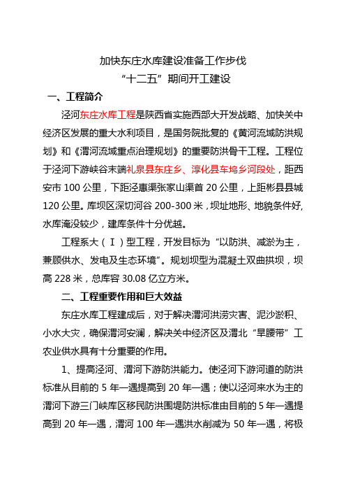
加快东庄水库建设准备工作步伐“十二五”期间开工建设一、工程简介泾河东庄水库工程是陕西省实施西部大开发战略、加快关中经济区发展的重大水利项目,是国务院批复的《黄河流域防洪规划》和《渭河流域重点治理规划》的重要防洪骨干工程。
工程位于泾河下游峡谷末端礼泉县东庄乡、淳化县车坞乡河段处,距西安市100公里,下距泾惠渠张家山渠首20公里,上距彬县县城120公里。
库坝区深切河谷200-300米,坝址地形、地貌条件好,水库淹没较少,建库条件十分优越。
工程系大(Ⅰ)型工程,开发目标为“以防洪、减淤为主,兼顾供水、发电及生态环境”。
规划坝型为混凝土双曲拱坝,坝高228米,总库容30.08亿立方米。
二、工程重要作用和巨大效益东庄水库工程建成后,对于解决渭河洪涝灾害、泥沙淤积、小水大灾,确保渭河安澜,解决关中经济区及渭北“旱腰带”工农业供水具有十分重要的作用。
1、提高泾河、渭河下游防洪能力。
使泾河下游河道的防洪标准从目前的5年一遇提高到20年一遇;使以泾河来水为主的渭河下游三门峡库区移民防洪围堤防洪标准由目前的5年一遇提高到20年一遇,渭河100年一遇洪水削减为50年一遇,将极大的提高渭河下游的防洪能力,同时为黄河的防洪发挥作用。
2、减少渭河下游及三门峡库区的泥沙淤积。
水库建成运行50年,通过调水调沙可拦泥沙20.2亿立方米,减少下游渭河泥沙淤积 4.73亿立方米,与三门峡水库联合运用可有效降低潼关高程,提高行洪能力,减淤效果明显。
3、提供关中地区工农业供水6亿立方米。
为泾惠渠灌区提供水量2.5亿立方米;为关中经济区的泾渭新区、铜川、富平等渭北地区提供工业和城镇供水水量3.5亿立方米。
(四)改善渭河下游生态环境。
提供渭河不少于20立方米/秒,泾河不少于2立方米/秒的常流量,使现有水环境和水质得到较大改善。
(五)装机8万千瓦。
年发电量3亿度。
【国家自然科学基金】_灌溉渠道_基金支持热词逐年推荐_【万方软件创新助手】_20140802
2010年 序号 1 2 3 4 5 6 7 8 9 10 11 12 13 14 15 16 17 18 19 20 21 22 23 24 25 26 27 28 29 30 31
推荐指数 3 2 1 1 1 1 1 1 1 1 1 1 1 1 1 1 1 1 1 1 1 1 1 1 1 1 1 1 1 1 1 1 1
2009年 序号 1 2 3 4 5 6 7 8 9 10 11 12 13 14 15 16 17 18 19 20 21 22 23 24 25 26 27 28 29 30
科研热词 黑河流域 随机前沿分析(sfa) 闸墩 量水槽 配水编组 贡献率 灌溉渠系 灌溉水利用系数 灌溉水利用率 灌溉水分生产率 灌区 渠道量水 泾惠渠灌区 水管理 水利工程 气候变化 模拟退火遗传算法 技术效率 径流变化 影响因素 张掖市 干旱区 地理信息系统 可持续发展 动态罚函数 分布式水文模型 优化 主成分分析法 swat mann-kendall检验
推荐指数 1 1 1 1 1 1 1 1 1 1 1 1 1 1 1 1 1 1 1 1 1 1 1
2013年 序号 1 2 3 4 5 6 7 8 9 10 11 12 13 14 15 16 17 18 19 20 21 22 23 24 25 26 27 28 29 30 31 32 33 34 35 36 37 38 39 40 41 42 43 44 45 46 47 48
推荐指数 2 2 2 1 1 1 1 1 1 1 1 1 1 1 1 1 1 1 1 1 1 1 1 1 1 1 1 1 1 1 1 1 1 1 1 1 1 1 1 1 1 1 1 1 1 1 1 1
Experimental investigation and numerical simulation for weakening the thermal fluctuations Tjunction
Experimental investigation and numerical simulation for weakening the thermal fluctuations in aT-junctionK.Gao a ,P.Wang b ,T.Lu a ,⇑,T.Song caCollege of Mechanical and Electrical Engineering,Beijing University of Chemical Technology,Beijing 100029,China bSchool of Energy and Power Engineering,Dalian University of Technology,Dalian 116024,China cChina Nuclear Power Technology Research Institute Co.,Ltd,Shenzhen 518124,Chinaa r t i c l e i n f o Article history:Received 25August 2014Received in revised form 17November 2014Accepted 4January 2015Available online 17January 2015Keywords:Experimental investigation Numerical simulation Tee junctionThermal fluctuationa b s t r a c tIn this work,the mixing processes of hot and cold fluids with and without a distributor are predicted by experiments and numerical simulations using large-eddy simulation (LES)on FLUENT platform.Temperatures at different positions of the internal wall and mixing conditions caused by T-junctions at different times are obtained,then the simulated normalized mean and root-mean square (RMS)temperature,velocity vector and temperature contour for the two structures,namely with and without a distributor,are compared.The results show that,compared with the a T-junction without a distributor,the mixing region of hot and cold water in the T-junction with distributor moves to the middle of the pipe,and the inclusion of the distributor reduces the temperature fluctuations of internal wall noticeably and makes the mixing of hot and cold water more efficient.Ó2015Elsevier Ltd.All rights reserved.1.IntroductionTee junction is a familiar structure that is universally used in pipeline systems of power plants,nuclear power plants and chemi-cal plants,it is often applied to mix hot and cold fluid of main and branch pipes.The fluctuations of fluid temperature are transported to the solid walls by heat convection and conduction.This can cause cyclical thermal stresses and subsequent thermal fatigue cracking of the piping (Lee et al.,2009).So far,leakage accidents took place in several light water and sodium cooled reactors due to thermal fati-gue.In 1998,a crack was discovered at a mixing tee in which cold water from a branch pipe flowed into the main pipe in the residual heat removal (RHR)system in a reactor in Civaux,France.Metallur-gical studies concluded that the crack was caused by a high degree of cycle thermal fatigue (Eric Blondet,2002).In 1990,sodium leak-age happened in the French reactor Superphenix (Ricard and Sperandio,1996).It has been established that mixing hot and cold sodium can induce temperature fluctuations and result in thermal fatigue (IAEA,2002).Therefore,it is significant to study how to weaken thermal fatigue of the piping wall to ensure the integrity and safety of the piping system in a nuclear power plant.In the analysis of thermal fatigue,temperature fluctuation is a very important evaluation parameter.A reliable lifetime assess-ment of these components is difficult because usually only thenominal temperature differences between the hot and cold fluids are known,whereas the instantaneous temperatures and heat fluxes at the surface are unknown (Paffumi et al.,2013).Kamaya and Nakamura (2011)used the transient temperature obtained by simulation to assess the distribution of thermal stress and fati-gue when cold fluid flowed into the main pipe from a branch pipe.Numerical simulation of flow in the tee has been carried out Simoneau et al.(2010)to get temperature and its fluctuation curves,and the numerical results were in good agreement with the experimental data.Through the analysis on thermal fatigue stress,it draw the conclusion that the enhanced heat transfer coef-ficient and the temperature difference between hot and cold fluids were primary factors of thermal fatigue failure of tees.Many numerical simulations and experiments have been carried out to evaluate the flow and heat transfer in a mixing tee junction (Metzner and Wilke,2005;Hu and Kazimi,2006;Hosseini et al.,2008;Durve et al.,2010;Frank et al.,2010;Jayaraju et al.,2010;Galpin and Simoneau,2011;Aulery et al.,2012;Cao et al.,2012).Turbulent models such as Reynolds-averaged Navier–Stokes (RANS),Unsteady Reynolds averaged Navier Stokes (URANS),Scale-Adaptive Simulation (SAS),Reynolds stress model (RSM),detached eddy simulations (DES),and LES have all been used in industrial applications.As one of the choices of turbulent model for predicting the mixing flow in tee junctions,the RSM can bemused to describe the momentum conservation of the mixing (Durve et al.,2010;Frank et al.,2010).Turbulent mixing phenomena in a T-junction have been numerically investigated using the k $x/10.1016/j.anucene.2015.01.0010306-4549/Ó2015Elsevier Ltd.All rights reserved.Corresponding author.based baseline Reynolds stress model(BSL RSM)(Frank et al.,2010) for two different cases.Durve et al.(2010)applied the RSM to pre-dict the velocityfield of three non-isothermal parallel jetsflowing in an experiment setup used to simulate theflow occurring at the core outlet region of a fast breeder reactor(FBR),with a Reynolds number of1.5Â104.Theflow in tube of different Reynolds numbers (Re)andflow velocity ratio were studied experimentally with three-dimensional scanning using particle image velocimetry(3D-SPIV) (Brücker,1997).Large-eddy simulation(LES)is an alternative turbulence model with different subgridscale models often employed to predict velocity and temperaturefluctuations.Indeed many numerical studies have shown the capability of LES to model thermalfluctu-ations in turbulent mixing.LES was performed(Lee et al.,2009)to analyze temperaturefluctuation in the tee junction and the simu-lated results were in good agreement with the experimental data. Thermal striping phenomena in the tee junction had been numer-ically investigated using LES(Hu and Kazimi,2006)for two differ-ent mixing cases,and the simulated normalized mean and root-mean square(RMS)was consistent with experimental results. LES in a mixing tee were carried out(Galpin and Simoneau, 2011)in order to evaluate the sensitivity of numerical results to the subgrid scale model by comparing the experimental results, and to investigate the possibility of reducing thefluid computa-tional domain at the inlet.Another simulation that mixing of a hot and a coldfluid stream in a vertical tee junction with an upstream elbow main pipe was carried out with LES(Lu et al., 2013).And the numerical results show that the normalized RMS temperature and velocity decrease with the increases of the elbow curvature ratio and dimensionless distance.In the meantime,many scholars have studied how to weaken the thermalfluctuation.Experiments and simulation were con-ducted(Wu et al.,2003)on a tee junction geometry with a sleeve tube in it.Theflow is divided into three types of jets by theflow velocity ratio in main and branch pipes.Through the analysis of flowfield and velocityfield of various jets types,it indicate that the addition of sleeve tube relieve the thermal shock caused by the coldfluid injection rge-eddy simulation have been used(Lu et al.,2010)to evaluate the thermal striping phe-nomena in tee junctions with periodic porous media,the temper-ature and velocityfield inside the tubes are obtained.The research revealed that the addition of a porous reduces the tem-perature and velocityfluctuations in the mixing tube.As mentioned above,experiments and numerical simulations for both tee junction geometry with a sleeve tube in it(Wu et al., 2003)and for a mixing tee with periodic porous media in it(Lu et al.,2010)have been carried out.The results of previous researches provide a good reference value for this work that anal-yses the role of distributor in weakening the thermalfluctuation of internal piping wall,and this structure has not been studied to date,to the best of our knowledge.In this work,mixing processes have been studied by the experiment and numerically predicted with LES.Then the simulated normalized mean and root-mean square(RMS)temperature,velocity vector and temperature con-tour of the two tees are compared.2.Experiment systemThe Experimentflowchart is presented in Fig.1.The experimen-tal system consists of four main components,a cold water supply line,a hot water supply line,a test section,and a data acquisition unit.The experiment device is shown in Fig.2.Experimentfluid was adjusted to the desired temperature by the heater and chiller, and then was pumped to the test section.After mixing thefluid is returned to the heater for recycling,some of the excessfluid is dis-charged through the overflow pipe.During the mixing of thefluids, the temperature of the mixingfluid is collected and recorded by the thermocouple probe installed on the tube wall.The experiment requires two different structures of the test sec-tion,Fig.3is the T-junction section without the branch liquid dis-tributor and Fig.4is that with the branch liquid distributor.The addition of this structure has two main functions:(1)changing the mixing position of hot and coldfluids:moving the mixing zone to the middle of the tube,and away from the main pipe wall;(2) increasing the intensity of mixing process:adding the fence near the outlet of distributor enhanced the mixed disturbance and the exacerbatedfluid mixing of the inner tube.For the convenience of observing and adjusting the mixing process,the test section is a round pipe made of plexiglass,and other pipes are made of steel. Fig.5is the physical model of the branch liquid distributor.The test conditions in the present experiment are shown in Table1.We collected the instantaneous temperature data of every measurement points by the data collector.The distribution of sam-pling points are shown in Fig.6,there are total eight thermocou-ples in the circumferential direction at each plane.In the T-junction section without the branch liquid distributor,the number of the collected plane is6(x/d m=1,2,3,4,6,8).That is to say there are48thermocouples in the structure without distributor.And in the T-junction section with the branch liquid distributor,the num-ber of the collected plane is5(x/d m=2,3,4,6,8),which means there are40thermocouples in the structure that with the distrib-utor.In both structures,the distance between measuring point the thermocouple probe and the inner wall is30mm.Since the collect-ing frequency of the collector is limited,we use1Hz as the collect-ing frequency after theflowfield is stable,and the total number of collection is800s.Table1shows the specific parameters of the test conditions.NomenclatureT time(s)Pr Prandtl numberLs mixing length of subgrid grid(m)T temperature(K)G acceleration of gravity(m/s2)K von Karman numberCs Smagorinsky numberS ij subgrid strain rate tensorM R momentum ratio of main pipe and branch pipe TÃnormalized mean temperaturesTÃrms normalized RMS temperaturesR d diameter ratioR v velocity ratiox,y,z axial coordinate(m)Greek symbolsqfluid density(kg/m3)b coefficient of thermal expansionl viscosity(Pa s)ltturbulent viscosity(Pa s)k thermal conductivity(w/(m k))C P heat capacity(J/(kg°C))K.Gao et al./Annals of Nuclear Energy78(2015)180–187181182K.Gao et al./Annals of Nuclear Energy78(2015)180–1871\4\11-thermometers 2\5\10-pressure gauge 3\9-flow meter 6-c ooler 7-heater8-overflow 12-test sec tion 13-thermoc ouple data c ollec torFig.1.Experimentflow chart.Fig.5.Physical model of the branch liquid distributor(a)the whole graph(b)theprofile map.Fig.2.Experiment device of thermalfluctuation.Fig.3.Schematic diagram of the T-junction section without the branch liquid distributor.Fig.4.Schematic diagram of the T-junction section with the branch liquid distributor.3.Numerical simulationFig.7is the numerical model based on the experimental section of T junction.The size of the model,boundary conditions are con-sistent with the experiment.In which,hot water enters from the left of main pipe,and cold water enters from the branch pipe,finally the mixingfluidflow out of the right of the main pipe.Dur-ing the calculation,the steady results offlowfield and heat transfer are obtained by Reynolds stress model(RSM)firstly,and then set @q@tþ@q u i@x i¼0ð1Þ@q u i@tþ@q u i u j@x j¼À@ p@x iÀq0bðTÀT0Þgþ@@x jlþltÀÁ@ u i@x jþ@ u j@x i!ð2Þ@q T@tþ@q Tu j@x j¼@@x jkc p@T@x jÀq T00u00j!ð3ÞIn these equations,q,b,l,l t,k and c p represent the density,ther-mal expansion coefficient,molecular viscosity,turbulent viscosity, thermal conductivity and specific heat capacity,respectively.The Smagorinsky–Lilly model is used for the turbulent viscosity,which is described as:lt¼q L2s j S jð4Þj S jTable1Experimental conditions.Main pipe Branch pipeFlow rate (m3/h)Temperature(K)Flow rate(m3/h)Temperature(K)Without distributor0.645304.650.270287.65With distributor0.645304.650.266287.65Fig.6.The distribution of sampling points on the planes.Physical model of T-junction(a)without the branch liquid distributor;(b)with the branch liquid distributor.K.Gao et al./Annals of Nuclear Energy78(2015)180–187183ij ¼12@ u i@x jþ@ u j@x ið7Þwhere k is the Von Karman constant of0.42;d is the distance to the closest wall;C s is the Smagorinsky constant of0.1;V is the volume of the computational cell.4.Results and discussionThe normalized mean and root-mean square temperature are used to describe the time-averaged temperature and temperature fluctuation intensity.The normalized temperature is defined as:ü1NX Ni¼1TÃið8ÞN is the total number of sample times.TÃi¼T iÀT cT hÀT cð9Þwhere T i is the transient temperature,T c is the coldfluid inlet tem-perature and T h is hotfluid inlet temperature.The root-mean square(RMS)of the normalized temperature is defined as:TÃrms¼ffiffiffiffiffiffiffiffiffiffiffiffiffiffiffiffiffiffiffiffiffiffiffiffiffiffiffiffiffiffiffiffiffiffiffiffiffiffiffiffi1X Ni¼1TÃiÀTÃ2rð10Þ184K.Gao et al./Annals of Nuclear Energy78(2015)180–187parison of experimental and numerical resultsAs can be seen from the Fig.8,the numerical normalized mean temperature distributions at the plane x/d m=1and the plane x/ d m=2are in good qualitative agreement and in adequate quantita-tive agreement,and most of them are within the experimental deviation of±20%.Meanwhile,the lifting trends of the data are the same.In the direction of180°,the mean temperatures are both minimal.And with the angle decrease to0°,the temperatures are gradually increased.Quantitative differences between the experi-ment and numerical results are that the normalized mean temper-atures given by LES are larger than the experimental data.That is because we did not add insulation unit on tube wall in the exper-iment,leading the transfer of some heat into the air.And in the process of numerical simulation,we ignored the convective heat transfer between the wall and the air.As shown in Fig.9,although the numerical results and experi-mental results have a little difference at the plane x/dm=2around the location of225°and the plane x/dm=2around the location of 0°and315°,all of them are within the error range that can be accepted.Both the simulations and experimental results give a lar-ger mean temperature in the top half of the main pipe than in the bottom half.This verifies the validity of the LES model for predict-ing the mixing of hot and coldfluids in a tee junction.The normalized RMS temperature on the plane x/d m=1and plane x/d m=2are shown in Fig.10,respectively.Similar to the nor-malized mean temperature,the normalized RMS temperature lines agree very well with the experiment ones.Both of the maximum values appear at the bottom half of the pipe.This indicates that the maximum temperaturefluctuations of main pipe appear on the opposite of the branch pipe inlet in this condition.As shown in Fig.11,the numerical results and the experimental results have the same trend and the numerical data are agreed well with the experimental ones.By comparison with Figs.4and5,dif-ferent from the temperaturefluctuations distribution which with-out the branch liquid distributor,there are two peaks of high fluctuation located at the90°and270°directions along with the tube.This is because the direction is that of the outlet of branch liquid distributor,the coldfluidflowing out from the outlet of branch liquid distributor mixes very fast with the hotfluid,leading to dramatic changes of temperature.In summary,the LES simulation results obtained are generally in good qualitative and quantitative agreement with the experi-mental data for the case of T-junction with/without the branch liquid distributor.Based on this,we analyzed the numerical results further.And the results are reported in the section below.4.2.Numerical results with/without branch liquid distributorThe numerical data were sampled on the inner wall in the plane x/ d m=À1,À0.5,0,0.5,1,2,3,4,6and8.At the same time,the numer-ical data were sampled from points every5mm along the intersec-tional lines of planes of y/d m=0and sections of x/d m=À2,À1,0,1,2, 3,4,5and6,to get the points with the maximum normalized rootK.Gao et al./Annals of Nuclear Energy78(2015)180–187185mean square temperatures in the tee and on the top and bottom walls.Here,the temperature and velocityfields were determined with LES simulations for the case of tee junction with/without branch liquid distributor.The temperature contours and velocity vectors for the T-junction are shown in Figs.12and13,respectively.As can be seen in Fig.12,due to the large branch pipeflow velocity,hot and coldfluid mixing zone is mainly located in both upstream and downstream region of the intersections of the main pipe and the branch pipe.The vigorous mixing offluids in the tube leads to thermalfluctuation on the wall.But in the T-junction with the branch liquid distributor,the mixing region moves to the lower half and downstream region of the main pipe.This indicates that the distributor is advantageous to weaken thermalfluctuations on the wall.The same conclusion can be seen from Fig.13,the dis-tributor weaken thermalfluctuations on the wall of downstream region and the top of the main pipe.186K.Gao et al./Annals of Nuclear Energy78(2015)180–187Fig.14compares the normalized mean temperatures between two tees of different structures.As can be seen,wall temperature changes great in the direction of90°,135°,225°and270°in T-junc-tion with the distributor,because the directions are the distributor outlet directions.This indicates that the coldfluid mixes with hot fluid on the wall afterflows out of the distributor.At the same time,the temperature in the direction of180°also changes dra-matically.That is because the coldfluid moves down in the effects of gravity and buoyancy.As shown in Fig.15,for the tee with distributor,the maximum values of normalized RMS temperature are smaller than that of the tee without distributor in most directions.This indicates that the adding of the distributor can relieve thermalfluctuations on the wall to some extent.And for the T-junction with distributor,tem-perature tends to be stable after the plane of x/d m=6,which indi-cates that twofluids have made a full mixing,while for the initial tee,temperature is still in the dramatic change,and this shows that the improved structure can effectively reduce the mixing length.Fig.16shows the maximum normalized instantaneous temper-aturefluctuations in the tee and on the top and bottom walls in the plane y/d m=0.In the tee,the maximum normalized instantaneous temperaturefluctuations of the case without distributor vary from 0.45to0.8,which means that the hot and coldfluids alternate in this location.However,for the case with distributor,the tempera-turefluctuations in the tee as well as on the top and bottom walls are much smaller than those of the case without distributor.That also implies that the distributor can reduce the temperaturefluctu-ation effectively.The normalized instantaneous temperaturefluctuations cannot describe the relationship between power spectrum density(PSD) and frequency of the temperaturefluctuation.PSD against fre-quency is one of the most important parameter for thermal fatigue analysis,which can directly show how PSD is in a certain fre-quency.The PSDs of the points with maximum temperaturefluctu-ation for the cases with and without distributor against frequency were recorded by fast Fourier transform(FFT)and shown in Fig.17. The temperaturefluctuation of the case without distributor has the highest PSD,at the frequency of0.04Hz,whereas the distributor significantly reduces the PSD of the temperaturefluctuations with the frequency from0.01to0.1Hz.In addition,the PSD of temper-aturefluctuations decreases with the frequency increasing.5.ConclusionsAs thermal stratification can result in thermal fatigue in the pip-ing system of a nuclear power plant,safety and integrity evaluation of the piping system has become an important issue.In this work the temperaturefluctuation has been studied by the experiment and numerically predicted by LES for two types of vertical tee junc-tion:one with distributor in the branch pipe and another without. The numerical results of normalized mean and RMS temperatures for the two structures have been found to be in good qualitative and quantitative agreement with the experimental data,which val-idates the use of LES simulations to evaluate convective mixing in such geometries.At the same time,the simulated normalized mean and root-mean square(RMS)temperature,velocity vector and temperature contour of the two tees are compared.The numerical results show that thefluctuations of temperatures of the tee without the distrib-utor are larger than those of the tee with the distributor,which can be explained by the branch liquid distributor enhancing the mix-ing.Although both tees give the same momentum ratio between the main pipeflow and the branch pipeflow,mixing and convec-tive heat transfer are greatly enhanced by the presence of the branch liquid distributor.These all show that the structure is effec-tive for weakening the thermalfluctuation of tee piping wall when hot and coldfluids mix,and it can make the mixing more sufficient.AcknowledgementsThis work was supported by projects of the National Natural Science Foundation of China(No.51276009),Program for New Century Excellent Talents in University(No.NCET-13-0651),and the National Basic Research Program of China(No.2011CB706900). ReferencesAulery, F.,Toutant, A.,Monod,R.,Brillant,G.,Bataille, F.,2012.Numerical simulations of sodium mixing in a T-junction.Appl.Therm.Eng.37,38–43.Brücker,C.,1997.Study of the three-dimensionalflow in a T-junction using a dual-scanning method for three-dimensional scanning-particle-image velocimetry (3-D SPIV).Exp.Therm.Fluid Sci.14,35–44.Cao,Q.,Lu,D.,Lv,J.,2012.Numerical investigation on temperaturefluctuation of the parallel triple-jet.Nucl.Eng.Des.249,82–89.Durve,A.,Patwardhan,A.W.,Banarjee,I.,Padmakumar,G.,Vaidyanathan,G.,2010.Thermal striping in triple jetflow.Nucl.Eng.Des.240,3421–3434.Eric Blondet, C.F.,2002.High cycle thermal fatigue in french PWR.In:10th International Conference on Nuclear Engineering.Arlington,Virginia,USA,pp.429–436.Frank,T.,Lifante,C.,Prasser,H.M.,Menter,F.,2010.Simulation of turbulent and thermal mixing in T-junctions using URANS and scale-resolving turbulence models in ANSYS CFX.Nucl.Eng.Des.240,2313–2328.Galpin,J.,Simoneau,J.P.,rge Eddy Simulation of a thermal mixing tee in order to assess the thermal fatigue.Int.J.Heat Fluid Flow32,539–545. Hosseini,S.M.,Yuki,K.,Hashizume,H.,2008.Classification of turbulent jets in a T-junction area with a90-deg bend upstream.Int.J.Heat Mass Transfer51,2444–2454.Hu,L.-W.,Kazimi,M.S.,2006.LES benchmark study of high cycle temperature fluctuations caused by thermal striping in a mixing tee.Int.J.Heat Fluid Flow 27,54–64.IAEA,2002.Validation of Fast Reactor Thermomechanical and Thermohydraulic Codes,Vienna.Jayaraju,S.T.,Komen,E.M.J.,Baglietto,E.,2010.Suitability of wall-functions in Large Eddy Simulation for thermal fatigue in a T-junction.Nucl.Eng.Des.240,2544–2554.Kamaya,M.,Nakamura, A.,2011.Thermal stress analysis for fatigue damage evaluation at a mixing tee.Nucl.Eng.Des.241,2674–2687.Lee,J.I.,Hu,L.-W.,Saha,P.,Kazimi,M.S.,2009.Numerical analysis of thermal striping induced high cycle thermal fatigue in a mixing tee.Nucl.Eng.Des.239, 833–839.Lu,T.,Jiang,P.X.,Guo,Z.J.,Zhang,Y.W.,Li,H.,rge-eddy simulations(LES)of temperaturefluctuations in a mixing tee with/without a porous medium.Int.J.Heat Mass Transfer53,4458–4466.Lu,T.,Liu,S.M.,Attinger,D.,rge-eddy simulations of structure effects of an upstream elbow main pipe on hot and coldfluids mixing in a vertical tee junction.Ann.Nucl.Energy60,420–431.Metzner,K.J.,Wilke,U.,2005.European THERFAT project—thermal fatigue evaluation of piping system‘‘Tee’’-connections.Nucl.Eng.Des.235,473–484. Paffumi, E.,Radu,V.,Nilsson,K.F.,2013.Thermal fatigue striping damage assessment from simple screening criterion to spectrum loading approach.Int.J.Fatigue53,92–104.Ricard,J.B.,Sperandio,M.,1996.Fracture mechanics applied to superphenix reactor components.Int.J.Pressure Vessels Piping65,295–301.Simoneau,J.-P.,Champigny,J.,Gelineau,O.,2010.Applications of large eddy simulations in nuclearfield.Nucl.Eng.Des.240,429–439.Wu,H.L.,Peng,X.F.,Chen,T.K.,2003.Influence of sleeve tube on theflow and heat transfer behavior at a T-junction.Int.J.Heat Mass Transfer46,2637–2644.K.Gao et al./Annals of Nuclear Energy78(2015)180–187187。
2019年度陕西高等教育教学改革研究项目名单(高职)
任春晓、张多、郝文斌、闫炳苍
一般
326
19GG013
陕西铁路工程职业技术学院,陕西工业职业技术学院,廊坊市中科建筑产业化创新研究中心
工程建设类高职院校“1+X证书制度”的研究与实践
王津
刘明学、黄艳妮、张学钢、赵东、杨小玉、张建奇
重点攻关
327
19GZ016
陕西铁路工程职业技术学院,萨马拉国立交通大学
中药制药技术专业“学历证书+若干职业技能等级证书”制度(1+X)的研究与实践
龙凤来
周博、王云云、余鸽、胡普辉、朱玲、云涛、叶树青、唐柳
一般
288
19GG004
陕西工业职业技术学院,宝鸡机床集团有限公司
“产教融合、协同创新”高水平智能制造技术技能人才培养的研究与实践
赵明威
苏宏志、张文亭、王建军、吴玉文
重点攻关
324
19GY021
陕西能源职业技术学院,陕西职业技术学院,西安交通大学,西电集团医院
产教融合背景下高职护理专业多元化人才培养模式改革与实践--以陕西能源职业技术学院为例
高正春
张扬、李娟、王瑜、何军、高雪、张娟
一般
325
19GY022
陕西能源职业技术学院,西安中医脑病医院
大健康背景下残疾人康复人才培养“五同四融合”新体系的实践与研究
高职院校人才培养质量评价机制研究与实践
王云江
杨益、吴灵辉、宁翠萍、董飞燕
重点攻关
282
19GG003
杨凌职业技术学院,陕西交通职业技术学院,咸阳职业技术学院
“一带一路”背景下高职建筑工程技术专业教学改革研究
刘洁
杨雪霁、王琦、卜伟、罗碧玉、雷海涛
灌溉与排水工程设计规范(doc 72页)
1 总则1.0.1 为统一灌溉与排水工程设计要求,提高工程设计质量,保证工程安全,节水节地,降低能耗,保护水环境,合理利用水土资源,充分发挥工程综合效益,制定本规范。
1.0.2 本规范适用于新建、扩建和改建的灌溉与排水工程设计。
1.0.3 灌溉与排水工程设计,必须认真执行国家有关技术经济政策,根据流域水利规划和区域水土资源平衡的要求,全面搜集分析所需资料,进行必要的勘察、观测和实验,积极采用新技术、新工艺、新材料,做到因地制宜,综合治理,经济实用,方便管理。
1.0.4灌溉与排水工程设计除应符合本规范外,尚应符合国家现行的有关标准的规定。
2 工程等级划分2.0.1蓄水枢纽工程等别应根据总蓄水容积的大小,按表2.0.1确定。
表2.0.1 蓄水枢纽工程分等指标工程等别ⅠⅡⅢⅣⅤ规模大(1)型大(2)型中型小(1)型小(2)型总蓄水容量(108m3)>1010~11~0.10.1~0.01<0.012.0.2引水枢纽工程等别应根据引水流量的大小,按表2.0.2确定。
表2.0.2 引水枢纽工程分等指标工程等别ⅠⅡⅢⅣⅤ规模大(1)型大(2)型中型小(1)型小(2)型引水流量(m3/s)>200200~5050~1010~2<22.0.3 提水枢纽工程等别应根据单站装机流量或单站装机功率的大小,按表2.0.3确定。
当提水枢纽工程按单站装机流量和单机装机功率分属两个不同工程等别时,应按其中较高的等别确定。
2.0.4 蓄水、引水和提水枢纽工程中的水工建筑物级别,应根据所属枢纽工程的等别与建筑物重要性,按表2.0.4确定。
表2.0.3 提水枢纽工程分等指标工程等别ⅠⅡⅢⅣⅤ规模大(1)型大(2)型中型小(1)型小(2)型单站装机流量(m3/s)>200200~5050~1010~2<2单站装机功率(MW)3030~1010~11~0.1<0.1注:“装机”系指包括备用机组在内的全部机组。
- 1、下载文档前请自行甄别文档内容的完整性,平台不提供额外的编辑、内容补充、找答案等附加服务。
- 2、"仅部分预览"的文档,不可在线预览部分如存在完整性等问题,可反馈申请退款(可完整预览的文档不适用该条件!)。
- 3、如文档侵犯您的权益,请联系客服反馈,我们会尽快为您处理(人工客服工作时间:9:00-18:30)。
,
提 高 了水资 源的利 用 率。
[ 关键 词 ] 续 灌调 配水 量 ; 灌调 配水量 ; 变调 配 水量研 究 轮 应
[ 中图分 类号 ] T 2 3 4 V 1 .
[ 文献标 识码 ] A
[ 文章 编号 】 1 0 0 4—1 8 2 1 0 14( 0 0) 5—0 5 0 2—0 2
Xa yn 0 0,S an i i ag 1 0 n 7 2 h ax)
Ab r a t s t c :Re s n b e d p o me to h ria in wa e n Jn h i u d src a n r a e t e i i ae fii n v Ac a o a l e ly n ft e ir t t ri i g u q it tc n i c e s h r g td e ce c g o i r —
.
Ke ywor ds: n i e pl y e to t r i i ai n; Rotto ri a in wa e lo a in; Co i g c lo a in o - Co tnu d de o m n fwa e ; r g to a in irg to t ra lc to ntn en v a lc t0 fwa
Re e r h o h u p r y t m fW a e srb to s a c n t e S p o tS se o t r Dit i u i n
Pln i g i i g u q r ia in Ch n e a n n n Jn h iu I rg t a n l o
.
c r i g t h e d r a e ,s d me t o c n r t n a d r if l T e a t l a e h e y h ta e t er o d n o t e h a wo k w t r e i n n e tai n an a1 h ri e t k st r e wa st a r h e—i ia e - c o C r g t d wa r
.
t ra lc to e lo a in, c r e irg t d wa e lo a in a d e e g nc e o m e iCl ri a e t ral c to n m r e y d ply nt T r u h a p i ai n o e wa e it b t n ma — h o g p l t ft t rd sr u i n c o h i o
LI Shua U ng, OU H Li—y a,ZH ANG a H i—bi n
( ・ se e o o s l ns C , T o g G a 2 1 , u n o g 2 X a y n n tue o rhtc r1 ein 1 C c c A c m C n ut t O. L D D n u n 5 3 0 G a g D n ; . i a g is tt f c i t a d s a 1 n i a eu g
刘 双 。侯 丽雅 张 海 宾 , ,
.
( ,中国市 政工 程西 北设 计研究 院有 限公 司东莞 分 院 , 1 广东 东莞 5 3 1 ; 陕 西省咸 阳市建 筑 设计 研究 院 , 2 10 2 陕 西 咸阳 720 1 0 0) [ 摘 要 ] 合理 调 配泾 惠渠灌 区水 量 , 高 灌 区灌 溉效 益 。根 据 渠 首来 水量 含 沙 量 与 降 雨 情 况 , 取 续 灌 调 提 采
第2 1 年 00 9月.
3 2卷
‘
= === === == : t== === =
第 L期 5
Gru d wa o地 下 水 e n tr
S p 2 1 e ., 0 0 Vo . 2 N0. 13 5
~
泾 惠渠 灌 区配 水 管 理 决 策 支 持 系 统 研究
,
e fc ie y a lv ae t e c n r d c i n b t e n s p l n e n f w t r Di e e iu to dfeen tr a lc t0 f t l l i t h o t ito e w e u p y a d d ma d o a e e v e a f r ntst a in if r twa e lo a in. t f he
、
配水量 、 灌调 配 水量和 应 变调 配水量 三种 方法 。通过 灌 区配 水管 理 决策 支持 系统 在 灌 区的应 用 三 种 水 量 调 配 方 轮 法提 高 了灌 区供 水调 蓄能 力 , 有效 缓 解灌 溉 用 水供 需 矛盾 。按 不 同情况 调 配 水量 将 有 限的 水 资 源进行 合 理 分 配 .
.
l twae e o r e s r a o a l iti u e ih i r v h t ia in r t fw t rr s u c s i t rr s u c s i e s n b y d sr t d wh c mp o e t e u i z t a e o a e e o r e mi b l o
.
a e e tde ii n s po s s e ,t r e d ply e pp o c e nh nc tr so a e c pa iy i he irg to t rs pp y g m n c so up  ̄ y t m h e e o m nta r a h s e a e wa e t r g a c