Ego-Motion Estimation Using Optical Flow Fields Observed from Multiple Cameras
光流法的作用
光流法的作用1. 什么是光流法光流法(Optical Flow)是计算机视觉领域中一种重要的运动估计方法,用于分析图像序列中的物体运动。
它通过分析相邻帧之间的像素强度变化来估计每个像素点在图像上的运动方向和速度。
在实际应用中,光流法可以用于目标跟踪、视觉里程计、三维重建和视频压缩等领域。
它对于理解和分析视频序列中的运动行为具有重要意义。
2. 光流法原理光流法基于一个假设:相邻帧之间相同物体上的像素点在时间上保持连续。
根据这个假设,我们可以通过比较两帧之间的像素强度差异来计算每个像素点在图像上的位移。
具体而言,光流法通过以下步骤实现:步骤一:特征提取首先需要从图像序列中提取出关键特征点,例如角点或边缘等。
这些特征点通常具有良好的区分性和稳定性,能够在不同帧之间进行匹配。
步骤二:特征匹配对于每个特征点,光流法通过在相邻帧之间进行搜索来找到其对应点。
一般采用的方法是在当前帧的局部区域内寻找与上一帧中特征点最相似的像素。
步骤三:光流计算通过比较特征点在两帧之间的位置变化,可以计算出光流向量,即每个像素点在图像上的运动方向和速度。
常用的光流计算方法有基于亮度约束和基于相关性约束等。
步骤四:光流可视化为了更直观地展示运动信息,可以将计算得到的光流向量以箭头或颜色等形式叠加在图像上,从而形成光流可视化结果。
3. 光流法的作用3.1 目标跟踪光流法可以用于目标跟踪,即在视频序列中实时追踪目标物体的位置和运动轨迹。
通过不断更新目标物体的位置信息,可以实现对其准确跟踪,并应用于视频分析、智能监控等领域。
3.2 视觉里程计视觉里程计是指通过分析相机连续拍摄的图像序列来估计相机在三维空间中的运动轨迹。
光流法可以用于计算相邻帧之间的相对位移,从而实现对相机运动的估计。
视觉里程计在自动驾驶、增强现实等领域具有重要应用价值。
3.3 三维重建光流法可以用于三维重建,即通过分析多个视角下的图像序列来恢复场景的三维结构。
通过计算不同视角之间的光流向量,可以估计出物体在空间中的位置和形状信息,从而实现对场景的三维重建。
Abstract
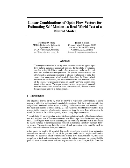
Linear Combinations of Optic Flow Vectors for Estimating Self-Motion–a Real-World Test of aNeural ModelMatthias O.FranzMPI f¨u r biologische KybernetikSpemannstr.38D-72076T¨u bingen,Germany mof@tuebingen.mpg.deJavaan S.ChahlCenter of Visual Sciences,RSBSAustralian National UniversityCanberra,ACT,Australiajavaan@.au AbstractThe tangential neurons in thefly brain are sensitive to the typical opticflow patterns generated during self-motion.In this study,we examinewhether a simplified linear model of these neurons can be used to esti-mate self-motion from the opticflow.We present a theory for the con-struction of an estimator consisting of a linear combination of opticflowvectors that incorporates prior knowledge both about the distance distri-bution of the environment,and about the noise and self-motion statisticsof the sensor.The estimator is tested on a gantry carrying an omnidirec-tional vision sensor.The experiments show that the proposed approachleads to accurate and robust estimates of rotation rates,whereas transla-tion estimates turn out to be less reliable.1IntroductionThe tangential neurons in thefly brain are known to respond in a directionally selective manner to wide-field motion stimuli.A detailed mapping of their local motion sensitivities and preferred motion directions shows a striking similarity to certain self-motion-induced flowfields(an example is shown in Fig.1).This suggests a possible involvement of these neurons in the extraction of self-motion parameters from the opticflow,which might be useful,for instance,for stabilizing thefly’s head duringflight manoeuvres.A recent study[2]has shown that a simplified computational model of the tangential neu-rons as a weighted sum offlow measurements was able to reproduce the observed response fields.The weights were chosen according to an optimality principle which minimizes the output variance of the model caused by noise and distance variability between differ-ent scenes.The question on how the output of such processing units could be used for self-motion estimation was left open,however.In this paper,we want tofill a part of this gap by presenting a classical linear estimation approach that extends a special case of the previous model to the complete self-motion problem.We again use linear combinations of localflow measurements but,instead of prescribing afixed motion axis and minimizing the output variance,we require that the quadratic error in the estimated self-motion parameters be as small as possible.From this0306090120150180−75−45−15154575azimuth (deg.)e l e v a t i o n (d e g .)Figure 1:Mercator map of the response field of the neuron VS7.The orientation of each arrow gives the local preferred direction (LPD),and its length denotes the relative local motion sensitivity (LMS).VS7responds maximally to rotation around an axis at an azimuth of about 30◦and an elevation of about −15◦(after [1]).optimization principle,we derive weight sets that lead to motion sensitivities similar to those observed in tangential neurons.In contrast to the previous model,this approach also yields the preferred motion directions and the motion axes to which the neural models are tuned.We subject the obtained linear estimator to a rigorous real-world test on a gantry carrying an omnidirectional vision sensor.2Modeling fly tangential neurons as optimal linear estimators for self-motion2.1Sensor and neuron modelIn order to simplify the mathematical treatment,we assume that the N elementary motion detectors (EMDs)of our model eye are arranged on the unit sphere.The viewing direction of a particular EMD with index i is denoted by the radial unit vector d i .At each viewing direction,we define a local two-dimensional coordinate system on the sphere consisting of two orthogonal tangential unit vectors u i and v i (Fig.2a ).We assume that we measure the local flow component along both unit vectors subject to additive noise.Formally,this means that we obtain at each viewing direction two measurements x i and y i along u i and v i ,respectively,given byx i =p i ·u i +n x,iandy i =p i ·v i +n y,i ,(1)where n x,i and n y,i denote additive noise components and p i the local optic flow vector.When the spherical sensor translates with T while rotating with R about an axis through the origin,the self-motion-induced image flow p i at d i is [3]p i =−µi (T −(T ·d i )d i )−R ×d i .(2)µi is the inverse distance between the origin and the object seen in direction d i ,the so-called “nearness”.The entire collection of flow measurements x i and y i comprises theoptic flow vectors LPD unit vectorsLMSs summationxa.b.Figure 2:a.Sensor model:At each viewing direction d i ,there are two measurements x i and y i of the optic flow p i along two directions u i and v i on the unit sphere.b.Simplified model of a tangential neuron:The optic flow and the local noise signal are projected onto a unit vector field.The weighted projections are linearly integrated to give the estimator output.input to the simplified neural model of a tangential neuron which consists of a weighted sum of all local measurements (Fig.2b )ˆθ=N iw x,i x i +N iw y,i y i (3)with local weights w x,i and w y,i .In this model,the local motion sensitivity (LMS)isdefined as w i = (w x,i ,w y,i ) ,the local preferred motion direction (LPD)is parallel to thevector 1w i(w x,i ,w y,i ).The resulting LMSs and LPDs can be compared to measurements on real tangential neurons.As our basic hypothesis,we assume that the output of such model neurons is used to es-timate the self-motion of the sensor.Since the output is a scalar,we need in the simplest case an ensemble of six neurons to encode all six rotational and translational degrees of freedom.The local weights of each neuron are chosen to yield an optimal linear estimator for the respective self-motion component.2.2Prior knowledgeAn estimator for self-motion consisting of a linear combination of flow measurements nec-essarily has to neglect the dependence of the optic flow on the object distances.As a consequence,the estimator output will be different from scene to scene,depending on the current distance and noise characteristics.The best the estimator can do is to add up as many flow measurements as possible hoping that the individual distance deviations of the current scene from the average will cancel each other.Clearly,viewing directions with low distance variability and small noise content should receive a higher weight in this process.In this way,prior knowledge about the distance and noise statistics of the sensor and its environment can improve the reliability of the estimate.If the current nearness at viewing direction d i differs from the the average nearness ¯µi over all scenes by ∆µi ,the measurement x i can be written as (see Eqns.(1)and (2))x i =−(¯µi u i ,(u i ×d i )) T R +n x,i −∆µi u i T ,(4)where the last two terms vary from scene to scene,even when the sensor undergoes exactlythe same self-motion.To simplify the notation,we stack all2N measurements over the entire EMD array in the vector x=(x1,y1,x2,y2,...,x N,y N) .Similarly,the self-motion components along the x-,y-and z-directions of the global coordinate systems are combined in the vector θ=(T x,T y,T z,R x,R y,R z) ,the scene-dependent terms of Eq.(4)in the2N-vector n=(n x,1−∆µ1u1T,n y,1−∆µ1v1T,....) and the scene-independent terms in the 6xN-matrix F=((−¯µ1u 1,−(u1×d1) ),(−¯µ1v 1,−(v1×d1) ),....) .The entire ensemble of measurements over the sensor can thus be written asx=Fθ+n.(5) Assuming that T,n x,i,n y,i andµi are uncorrelated,the covariance matrix C of the scene-dependent measurement component n is given byC ij=C n,ij+Cµ,ij u i C T u j(6) with C n being the covariance of n,Cµofµand C T of T.These three covariance matrices, together with the average nearness¯µi,constitute the prior knowledge required for deriving the optimal estimator.2.3Optimized neural modelUsing the notation of Eq.(5),we write the linear estimator asˆθ=W x.(7) W denotes a2N x6weight matrix where each of the six rows corresponds to one model neuron(see Eq.(3))tuned to a different component ofθ.The optimal weight matrix is chosen to minimize the mean square error e of the estimator given bye=E( θ−ˆθ 2)=tr[W CW ](8) where E denotes the expectation.We additionally impose the constraint that the estimator should be unbiased for n=0,i.e.,ˆθ=θ.From Eqns.(5)and(7)we obtain the constraint equationW F=16x6.(9) The solution minimizing the associated Euler-Lagrange functional(Λis a6x6-matrix of Lagrange multipliers)J=tr[W CW ]+tr[Λ (16x6−W F)](10) can be found analytically and is given byW=12ΛF C−1(11)withΛ=2(F C−1F)−1.When computed for the typical inter-scene covariances of a flying animal,the resulting weight sets are able to reproduce the characteristics of the LMS and LPD distribution of the tangential neurons[2].Having shown the good correspondence between model neurons and measurement,the question remains whether the output of such an ensemble of neurons can be used for some real-world task.This is by no means evi-dent given the fact that-in contrast to most approaches in computer vision-the distance distribution of the current scene is completely ignored by the linear estimator.3Experiments3.1Linear estimator for an office robotAs our test scenario,we consider the situation of a mobile robot in an office environment. This scenario allows for measuring the typical motion patterns and the associated distance statistics which otherwise would be difficult to obtain for aflying agent.-75-45-15e l e v a t i o n (d e g .)a.Figure 3:Distance statistics of an indoor robot (0azimuth corresponds to forward direc-tion):a.Average distances from the origin in the visual field (N =26).Darker areas represent larger distances. b.Distance standard deviation in the visual field (N =26).Darker areas represent stronger deviations.The distance statistics were recorded using a rotating laser scanner.The 26measurement points were chosen along typical trajectories of a mobile robot while wandering around and avoiding obstacles in an office environment.The recorded distance statistics therefore reflect properties both of the environment and of the specific movement patterns of the robot.From these measurements,the average nearness ¯µi and its covariance C µwere computed (cf.Fig.3,we used distance instead of nearness for easier interpretation).The distance statistics show a pronounced anisotropy which can be attributed to three main causes:(1)Since the robot tries to turn away from the obstacles,the distance in front and behind the robot tends to be larger than on its sides (Fig.3a ).(2)The camera on the robot usually moves at a fixed height above ground on a flat surface.As a consequence,distance variation is particularly small at very low elevations (Fig.3b ).(3)The office environment also contains corridors.When the robot follows the corridor while avoiding obstacles,distance variations in the frontal region of the visual field are very large (Fig.3b ).The estimation of the translation covariance C T is straightforward since our robot can only translate in forward direction,i.e.along the z -axis.C T is therefore 0everywhere except the lower right diagonal entry which is the square of the average forward speed of the robot (here:0.3m/s).The EMD noise was assumed to be zero-mean,uncorrelated and uniform over the image,which results in a diagonal C n with identical entries.The noise standard306090120150180-75-45-15154575azimuth (deg.)e l e v a t i o n (d e g .)a.azimuth (deg.)e l e v a t i o n (d e g .)b.Figure 4:Model neurons computed as part of the linear estimator.Notation is identical to Fig.1.The depicted region of the visual field extends from −15◦to 180◦azimuth and from −75◦to 75◦elevation.The model neurons are tuned to a .forward translation,and b .to rotations about the vertical axis.deviation of 0.34deg./s was determined by presenting a series of natural images moving at 1.1deg./s to the flow algorithm used in the implementation of the estimator (see Sect.3.2).¯µ,C µ,C T and C n constitute the prior knowledge necessary for computing the estimator (Eqns.(6)and (11)).Examples of the optimal weight sets for the model neurons (corresponding to a row of W )are shown in Fig.4.The resulting model neurons show very similar characteristics to those observed in real tangential neurons,however,with specific adaptations to the indoor robot scenario.All model neurons have in common that image regions near the rotation or translation axis receive less weight.In these regions,the self-motion components to be esti-mated generate only small flow vectors which are easily corrupted by noise.Equation (11)predicts that the estimator will preferably sample in image regions with smaller distance variations.In our measurements,this is mainly the case at the ground around the robot (Fig.3).The rotation-selective model neurons weight image regions with larger distances more highly,since distance variations at large distances have a smaller effect.In our exam-ple,distances are largest in front and behind the robot so that the rotation-selective neurons assign the highest weights to these regions (Fig.3b ).3.2Gantry experimentsThe self-motion estimates from the model neuron ensemble were tested on a gantry with three translational and one rotational (yaw)degree of freedom.Since the gantry had a position accuracy below 1mm,the programmed position values were taken as ground truth for evaluating the estimator’s accuracy.As vision sensor,we used a camera mounted above a mirror with a circularly symmetric hyperbolic profile.This setup allowed for a 360◦horizontal field of view extending from 90◦below to 45◦above the horizon.Such a large field of view considerably improves the estimator’s performance since the individual distance deviations in the scene are more likely to be averaged out.More details about the omnidirectional camera can be found in [4].In each experiment,the camera was moved to 10different start positions in the lab with largely varying distance distributions.After recording an image of the scene at the start position,the gantry translated and rotated at various prescribed speeds and directions and took a second image.After the recorded image pairs (10for each type of movement)were unwarped,we computed the optic flow input for the model neurons using a standard gradient-based scheme [5].e s t i m a t o r r e s p o n s e [%]46810121416182022468101214161820true self-motione s t i m a t e d s e lf -m o t i o ntranslationrotationa.b.Figure 5:Gantry experiments:Results are given in arbitrary units,true rotation values are denoted by a dashed line,translation by a dash-dot line.Grey bars denote translation estimates,white bars rotation estimates a.Estimated vs.real self-motion;b.Estimates of the same self-motion at different locations;c.Estimates for constant rotation and varying translation;d.Estimates for constant translation and varying rotation.The average error of the rotation rate estimates over all trials (N=450)was 0.7◦/s (5.7%rel.error,Fig.5a ),the error in the estimated translation speeds (N=420)was 8.5mm/s (7.5%rel.error).The estimated rotation axis had an average error of magnitude 1.7◦,the estimated translation direction 4.5◦.The larger error of the translation estimates is mainly caused by the direct dependence of the translational flow on distance (see Eq.(2))whereas the rotation estimates are only indirectly affected by distance errors via the current translational flow component which is largely filtered out by the LPD arrangement.The larger sensitivity of the translation estimates can be seen by moving the sensor at the same translation and rotation speeds in various locations.The rotation estimates remain consis-tent over all locations whereas the translation estimates show a higher variance and also a location-dependent bias,e.g.,very close to laboratory walls (Fig.5b ).A second problem for translation estimation comes from the different properties of rotational and translational flow fields:Due to its distance dependence,the translational flow field shows a much wider range of values than a rotational flow field.The smaller translational flow vectors are often swamped by simultaneous rotation or noise,and the larger ones tend to be in the upper saturation range of the used optic flow algorithm.This can be demonstrated by simultane-ously translating and rotating the semsor.Again,rotation estimates remain consistent while translation estimates are strongly affected by rotation (Fig.5c and d ).4ConclusionOur experiments show that it is indeed possible to obtain useful self-motion estimates from an ensemble of linear model neurons.Although a linear approach necessarily has to ignore the distances of the currently perceived scene,an appropriate choice of local weights and a largefield of view are capable of reducing the influence of noise and the particular scene distances on the estimates.In particular,rotation estimates were highly accurate-in a range comparable to gyroscopic estimates-and consistent across different scenes and different simultaneous translations.Translation estimates,however,turned out to be less accurate and less robust against changing scenes and simultaneous rotation.The components of the estimator are simplified model neurons which have been shown to reproduce the essential receptivefield properties of thefly’s tangential neurons[2].Our study suggests that the output of such neurons could be directly used for self-motion esti-mation by simply combining them linearly at a later integration stage.As our experiments have shown,the achievable accuracy would probably be more than enough for head stabi-lization under closed loop conditions.Finally,we have to point out a basic limitation of the proposed theory:It assumes linear EMDs as input to the neurons(see Eq.(1)).The output offly EMDs,however,is only linear for very small image motions.It quickly saturates at a plateau value at higher image velocities.In this range,the tangential neuron can only indicate the presence and the sign of a particular self-motion component,not the current rotation or translation velocity.A linear combination of output signals,as in our model,is no more feasible but would require some form of population coding.In addition,a detailed comparison between the linear model and real neurons shows characteristic differences indicating that tangential neurons usually operate in the plateau range rather than in the linear range of the EMDs[2].As a conse-quence,our study can only give a hint on what might happen at small image velocities.The case of higher image velocities has to await further research.AcknowledgmentsThe gantry experiments were done at the Center of Visual Sciences in Canberra.The authors wish to thank J.Hill,M.Hofmann and M.V.Srinivasan for their help.Finan-cial support was provided by the Human Frontier Science Program and the Max-Planck-Gesellschaft.References[1]Krapp,H.G.,Hengstenberg,B.,&Hengstenberg,R.(1998).Dendritic structure and receptive field organization of optic low processing interneurons in thefly.J.of Neurophysiology,79,1902-1917.[2]Franz,M.O.&Krapp,H C.(2000).Wide-field,motion-sensitive neurons and matchedfilters for opticflowfields.Biol.Cybern.,83,185-197.[3]Koenderink,J.J.,&van Doorn,A.J.(1987).Facts on opticflow.Biol.Cybern.,56,247-254.[4]Chahl,J.S,&Srinivasan,M.V.(1997).Reflective surfaces for panoramic imaging.Applied Optics,36(31),8275-8285.[5]Srinivasan,M.V.(1994).An image-interpolation technique for the computation of opticflow and egomotion.Biol.Cybern.,71,401-415.。
calcopticalflowfarneback原理讲解

calcopticalflowfarneback原理讲解calcopticalflowfarneback是OpenCV中的一个函数,用于计算稠密光流(dense optical flow)。
它基于Farneback的算法,可以估计图像中每个像素点的运动信息。
Farneback算法的原理如下:
1. 对于输入的两帧图像,首先将它们转换为灰度图像,以便更好地处理光流计算。
2. 然后,通过对灰度图像应用高斯滤波器来减少噪声。
这一步骤有助于提取稳定的特征点,并减小光流计算中的误差。
3. 接下来,使用多项式展开来近似两帧图像之间的局部区域。
多项式展开在空间和时间上都是平滑的,并且可以描述图像中像素点之间的关系。
4. 对于每个像素点,通过比较两帧图像中的多项式系数,计算出其在x和y方向上的光流向量。
这种比较是通过计算亮度差异、梯度信息和时间变化得到的。
5. 最后,通过插值方法将计算得到的稀疏光流向量转换为稠密光流场。
插值方法可以填补光流场中未计算的像素点,使得整个图像都有对应的光流向量。
总结起来,`calcopticalflowfarneback`函数使用Farneback算法来估计图像中每个像素点的运动信息。
它通过多项式展开、亮度差异、梯度信息和时间变化等特征来计算稠密光流向量,并使用插值方法将稀疏光流向量转换为稠密光流场。
这种稠密光流可以用于运动跟踪、目标检测等计算机视觉任务。
1。
光流法原理

光流法原理光流法是一种计算机视觉技术,用于估计图像序列中物体的运动。
它通过分析相邻帧之间的像素强度变化来推断物体的运动方向和速度。
在计算机视觉和机器人领域中,光流法是一种非常重要的技术,被广泛应用于运动分析、目标跟踪和环境感知等方面。
光流法的原理基于两个假设:首先,相邻帧之间的像素强度变化是由于物体的运动引起的;其次,相邻像素之间的运动是连续的,即相邻像素之间的运动方向和速度是相似的。
基于这些假设,光流法通过计算相邻帧之间像素的运动来推断物体的运动。
光流法的计算过程可以分为两个步骤:首先,对于每个像素,计算它在相邻帧之间的位移;其次,通过这些位移来估计物体的运动方向和速度。
在计算像素位移时,光流法通常采用互相关法或最小二乘法。
互相关法是一种计算两个信号之间相关性的方法,它可以用于计算相邻帧之间像素的相似性。
最小二乘法是一种最小化误差的方法,它可以用于计算像素之间的位移向量。
在计算物体的运动方向和速度时,光流法通常采用不同的技术,如基于梯度的方法、基于约束的方法和基于稀疏性的方法等。
基于梯度的方法通过计算像素之间的梯度来估计物体的运动方向和速度。
基于约束的方法通过定义运动方向和速度的约束条件来估计物体的运动。
基于稀疏性的方法则通过选择一些关键点来估计物体的运动,这些关键点通常是图像中的角点或者边缘。
光流法的应用非常广泛,它可以用于运动分析、目标跟踪和环境感知等方面。
在运动分析方面,光流法可以用于分析物体的运动轨迹和速度,从而提取物体的运动特征。
在目标跟踪方面,光流法可以用于跟踪移动的目标,从而实现目标的自动追踪。
在环境感知方面,光流法可以用于分析场景中的运动和变化,从而提高机器人的环境感知能力。
总之,光流法是一种非常重要的计算机视觉技术,它可以用于分析图像序列中物体的运动。
它的原理基于两个假设:相邻帧之间的像素强度变化是由于物体的运动引起的,相邻像素之间的运动方向和速度是相似的。
通过计算像素的位移和物体的运动方向和速度,光流法可以实现运动分析、目标跟踪和环境感知等应用。
逆向光流法-概述说明以及解释
逆向光流法-概述说明以及解释1.引言1.1 概述逆向光流法(Inverse Optical Flow)是计算机视觉领域研究的一种重要技术,它能够通过对图像序列进行分析,准确地估计出图像中每个像素点的运动方向和速度。
与正向光流法(Forward Optical Flow)相比,逆向光流法更加关注从下一帧图像到当前帧图像的像素点运动。
在逆向光流法中,首先通过某种方式获取到两个连续帧之间的光流场。
光流场指的是图像中每个像素点的运动矢量,表示了每个像素点从当前帧到下一帧的位移情况。
然后,通过使用一种反向计算的方法,即从下一帧到当前帧的光流估计方法,逆向光流法能够精确地得到每个像素点的运动信息。
逆向光流法的应用非常广泛。
在计算机视觉领域,逆向光流法能够被用于运动目标检测与跟踪、视频压缩、图像编辑等多个方面。
例如,在运动目标检测与跟踪中,逆向光流法可以有效地跟踪目标的运动轨迹,提供重要的目标位置信息;在视频压缩中,逆向光流法可以通过对图像运动的分析,减少视频序列中冗余的像素信息,从而实现更高效的压缩。
然而,逆向光流法也存在一些局限和挑战。
首先,由于图像中像素点的运动是一个多样性和非线性的问题,逆向光流法在处理某些特殊情况下可能会出现估计不准确的情况。
其次,逆向光流法对图像序列中的光照变化和纹理缺失等情况非常敏感,这也会进一步影响估计的准确性。
综上所述,逆向光流法是一项重要且有广泛应用的技术,在计算机视觉领域具有重要的研究和实际价值。
随着计算机硬件和算法的不断进步,逆向光流法在未来有望取得更好的性能和应用效果。
1.2文章结构1.2 文章结构本文将按照以下结构展开对逆向光流法的介绍和探讨:1.2.1 研究背景在本节中,将概述光流法的背景和发展,引出逆向光流法在光流研究中的重要性和应用场景。
1.2.2 逆向光流法的原理本节将详细介绍逆向光流法的基本原理,包括光流估计的数学模型和基本假设。
将介绍逆向光流法的计算步骤和关键概念,以及与其他光流法的区别和联系。
Unsupervised Learning of Depth and Ego-Motion from Video

2018年5月28日
1
2017CVPR 摘要:
提出了一个无监督的学习框架,用于从非结构化视频序列 中单眼深度和相机运动估计的任务 使用视点合成的端到端学习方法作为监控信号 与之前的工作相比,我们的方法完全无监督,只需要单眼 视频序列进行训练 本文方法使用单视图深度和多视图姿态网络,基于使用计 算出的深度和姿态使目标翘曲附近视点的损失 网络因此在训练期间由于损失而联合,但可以在测试时间 独立地应用
最终目标:
5
2017CVPR
6
2017CVPR Single-view depth estimation
在大型Cityscapes数据集实验效果
7
2017CVPR
8
2017CVPR
Make 3D
9
2017CVPR Pose estimation
为了更好地理解我们的姿态估计 结果,我们在图9中示出了在序 列的开始和结束之间具有不同的 侧旋的ATE曲线。 图9表明,当 侧向旋转很小时(即,车辆大部 分向前行驶),我们的方法比 ORB-SLAM(短)好得多,并且 在整个频谱上与ORB-SLAM(全 部)相当。 我们与ORB-SLAM (简称)之间的巨大性能差距表 明我们所学的自我运动可能可以 用作单眼SLAM系统中局部估计 模块的ew synthesis as supervision
3
2017CVPR Differentiable depth image-based rendering
4
2017CVPR Modeling the model limitation
Overcoming the gradient locality
高速摄像技术在两相流场籽粒运动测量中的应用
2 结果 与分析
21 物 料籽 粒运 动参 数 的分析 步骤 . 本 试验 所用 的图像 处 理软件 是 高速摄 像 机 自带 的处 理控 制 软件 ,首先 在 软件 中 M aue et esrm n 菜单
的应用为例 , 绍高速摄像技术在气一 介 固两相流籽
粒 运 动测 量 中的 应用 , 旨在 说 明 当 前 高 速 摄 像 技 术 的特 点 及 用 于 多相 流 场 物料 籽粒 运 动 规 律 研 究
R p rFl( 立 / 开一份 报 告文 件) e ot i 建 e 打 ,然 后设 置 坐
l 高速摄像 系统及试验装置
1 高速摄像系统 . 1 试验用高速摄像系统主要 由高速摄像机( 国 美
收 稿 日期 :2 0 — 3 0 07 0—9
标原点 。这些都设 置完了 以后就可 以利 用 M a— es
维普资讯
第4 期
周福君等 :高速摄像技术在两相流场籽粒运动测量中的应用
・ 3・ 2
帧 图像 上的 轴 和 y轴方 向位移 ,可 以以文本 的形 式打开 。根据数 据得 到籽粒运 动 的轨迹 见 图 5 。
‘
暑
;
星
图 1 第 1 籽 粒 跟 踪 图 像 幅
气力式振动输送试验台振动频率为 4 0 ・ i 、 5 mn r 振幅为 1 m 5 m、振动底板 的倾斜角度为 l。 5 。为了
增 加流 场 中物 料 籽粒 与背景 的对 比度 和 吸收 杂乱 的 反 射光 ,拍摄 背景 采用 白色 的麻 面 白纸 。摄像 机拍
摄像技术在流场测试方面的应用。一方面 ,由于帧 记录速度低 ,测量仅限于低速流场,另一方面 ,由 于籽粒像点采用人工判读 ,图像处理效率很低。进
- 1、下载文档前请自行甄别文档内容的完整性,平台不提供额外的编辑、内容补充、找答案等附加服务。
- 2、"仅部分预览"的文档,不可在线预览部分如存在完整性等问题,可反馈申请退款(可完整预览的文档不适用该条件!)。
- 3、如文档侵犯您的权益,请联系客服反馈,我们会尽快为您处理(人工客服工作时间:9:00-18:30)。
Ego-Motion Estimation Using Optical Flow Fields Observed from Multiple Cameras
An-Ting Tsaot Yi-Ping Hung$ Chiou-Shann Fuht Yong-Sheng Chent
t Dept. of Computer Science and Information Engineering, National Taiwan University, Taiwan
$ Institute of Information Science, Academia Sinica, Taipei, Taiwan
Email: hung@iis.sinica.edu.tw
Abstract In this paper, we consider a multi-camera vision system mounted on a moving object in a static three- dimensional environment. By using the motion flow
fields seen by all of the cameras, an algorithm which does not need to solve the point-correspondence prob- lem among the cameras is proposed to estimate the 30
ego-motion parameters of the moving object. Our ex- periments have shown that using multiple optical flow
fields obtained from different cameras can be very help- ful for
ego-motion estimation.
1 Introduction Three-dimensional ego-motion estimation has been one of the most important problems for the applica- tion of computer vision in mobile robots [lo]. Accu- rate estimation of ego-motion is very helpful for hu- man computer interaction and short-term control such as braking, steering, and navigation. In the past, there have been many methods [l,
6, 7,
121 which use flow vectors as the basis of their deriva-
tions for motion estimation. No matter their deriva- tions are linear or nonlinear, the flow vectors are ob- served by using single camera. However, there are some drawbacks on using only one camera. First, one can only solve the translation up to the direction, i.e., the absolute scale cannot be determined. This is the well known scaling factor problem. Second, the size of view field substantially affects the accuracy of 3D ego-
motion estimation. Third, the solution is not unique, which is the most serious problem. Given a flow field observed from one camera, it may be interpreted as two different kinds of motions. Let us consider a moving vehicle with two cameras
mounted on the left and right sides. Assume there are only two types of motions: one is pure translation to- ward the front direction and the other is pure rotation around the vertical axis. Now, Suppose we have only
1063-6919/97 $10.00 0 1997
IEEE
the left camera. The flow fields generated by the pure translation and the pure rotation are very similar if the field of view of the camera is not large enough. It is
hard to distinguish from this single flow field whether the motion is pure translation or pure rotation. Next, let us consider the left and right cameras to-
gether on this moving vehicle. If there is only trans-
lation, the optical flows observed from the two cam- eras will be the same in scale but opposite in direction. If there is only rotation, the optical flows will be the
same in both the scale and the direction. Therefore, if we can combine the information contained in the two flow fields appropriately, it will be easier to solve the ambiguity problem. There are many methods [2, 9, 141 of using multi-
camera vision systems to estimate the 3D motion pa-
rameters. Most of these systems need to solve the spa- tial point correspondence problems among all of the cameras. Hence, in a multi-camera vision system, the
view fields of the cameras are usually arranged to be overlapping in order to determine the 3D positions of
feature points by triangulation. Thus, this kind of ap-
proach did not enjoy the fact that the estimation ac- curacy can be improved by increasing the field of view. Besides, it is not easy to achieve high correction rate when trying to solve the spatial correspondence prob- lem. We propose to solve the 3D ego-motion estimation
problem by a multi-camera system without overlap-
ping view fields. This idea implies: 1) we can obtain
a very large view field by using several low-cost small- view-angle cameras, and 29 we do not have to solve the
spatial correspondence problem. Based on this idea, we have developed a new algorithm for 3D ego-motion
estimation. In this paper, we consider a multi-camera vision sys-
tem mounted on a moving object (e.q., human or air-
craft) in a static three-dimensional environment. A
special case of 3D ego-motion, vehicle-type 3D motion,
has been discussed in a previous paper [lo]. By us-
457