外文翻译----PLC在冰蓄冷中央空调系统控制中的应用
中央空调PLC控制系统
中央空调PLC控制系统本文介绍了中央空调风冷螺杆式冷水机组的原理和方法,以西门子S7-200可编程控制器为核心,对硬件结构和特点及软件的设计均作了相应的介绍,并对压缩机能量的控制加入了水温变化率的因素。
标签:中央空调;风冷螺杆式冷水机组;PLC;压缩机1、概述在制冷暖通行业螺杆式风冷冷水机组是最为通用的一类中央空调主机,而以单片机为核心的控制系统,在用户实际使用时,反应其在控制的可靠性、灵活性上均存在着不足之处,从而造成动作失灵甚至烧毁压缩机的事故。
西门子S7-200可編程控制器具有较高的性能价格比,从硬件质量和可靠性及防护等级上均比单片机控制器有更好的表现。
我们依据风冷螺杆式冷水机组的各种控制要求,设计了以S7-200系列PLC为控制核心的控制系统,经过实际应用系统稳定可靠,获得了令人满意的效果。
2、系统功能及控制要求2.1 启动停机控制按照相应的顺序和时间依次控制机组各功能部件的启停,完成开机和停机的功能。
螺杆压缩机启动和停机时要求首先以25%能量状态运行30秒,再进入相应的程序。
2.2 故障保护和报警机组运行时各故障检测点的开关信号输入PLC,由PLC控制各类故障信号产生相应的动作和报警,同时对各类模拟量和温度模块的状态进行监测。
2.3 压缩机运行及自动切换根据设定的温度值启停压缩机,在当前压缩机运行10分钟后仍不能满足设定温度要求,则启动下一台压缩机,在温度达到要求后,停止所有压缩机,在下次需启动压缩机时,根据程序中各压缩机的运行时间,优先启动运行时间短的压缩机,这样保证多台压缩机运行的时间和启动的次数基本均衡。
2.4 定时运行按照用户设定的开关机时间启停机组。
2.5 其他功能压缩机运行时间累计,压缩机能量调节,喷液阀控制等。
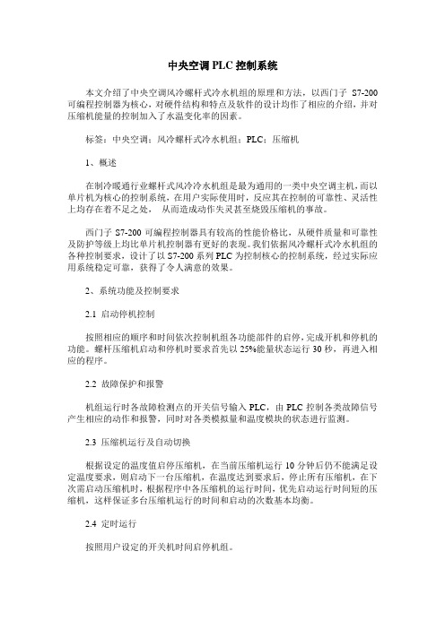
3、系统硬件构成及特点系统硬件控制方案如图1所示。
系统以常见的两台半封闭螺杆压缩机组成的系统为例,我们选用西门子S7-200CPU226作为控制核心,EM231热电阻模块配PT100铂电阻采集温度信号,在PLC中直接调用无需其他运算处理。
PLC在中央空调中的应用
机电控制与可编程程序控制器技术课程设计任务书课题名称:plc在中央空调上的应用学校:专业:姓名:学号:1 绪论1.1 选题背景及研究意义随着国民经济的发展和人民生活水平的同益提高,中央空调系统己广泛应用于工业与民用建筑域,如宾馆、酒店、写字楼、商场、厂房等场所,用于保持整栋大厦温度恒定。
如今,人们对中央空调系统提出新的要求就是舒适节能,要求在能耗更低的情况下保持室内合适的温度、湿度,让使用者感觉最舒适。
新建的中央空调系统在按照舒适节能的目标设计,而越来越多的使用多年的中央空调控制系统在进行改造以实现节能、舒适的目的。
据统计,中央空调的用电量占各类大厦总用电量的60%以上,其中,仅水泵的耗电量约占到空调系统耗电量的20—40%,存在巨大的能源浪费。
传统的设计中,中央空调的制冷机组、冷冻循环水系统、冷却循环水系统、冷却塔风机系统、盘管风机系统等的容量基本是按照建筑物最大制冷、制热负荷或新风交换量需求选定的,且留有充足余量。
无论季节、昼夜和用户负荷的怎样变化,各电机都长期固定在工频状态下全速运行,虽然可满足最大的用户负荷,但不具备随用户负荷动态调节系统功率的特性,而在大多数时间里,用户负荷是较低的,这样就造成很大的能源浪费。
近年来节能降耗被国家摆到空前重要的位置。
而国家供电紧张形势依然没有根本缓解,电价不断上调,造成中央空调系统运行费用上升,如何控制空调系统的电能费用己经成为越来越多空调的经营管理者所关注的问题。
故采用变频调速技术节约低负荷时主压缩机系统和水泵的电能消耗,具有极其重要的经济意义。
1.2 PLC控制国内外发展现状1.2.1 PLC的发展历程在工业生产过程中,大量的开关量顺序控制,它按照逻辑条件进行顺序动作,并按照逻辑关系进行连锁保护动作的控制,及大量离散量的数据采集。
传统上,这些功能是通过气动或电气控制系统来实现的。
1968年美国GM(通用汽车)公司提出取代继电气控制装置的要求,第二年,美国数字设备公司(DEC)研制出了基于集成电路和电子技术的控制装置,首次采用程序化的手段应用于电气控制,这就是第一代可编程序控制器,称Programmable ,是世界上公认的第一台PLC. 限于当时的元器件条件及计算机发展水平,早期的PLC主要由分立元件和中小规模集成电路组成,可以完成简单的逻辑控制及定时、计数功能。
PLC和变频器在中央空调节能改造中的应用
调 节 能改造 中的应 用 [ J 1 . 建 筑工程 技 术
与设 计 , 2 0 1 6 ( 1 6 ) : 1 I 2 3 - I i 2 3 .
用模式 。其中 电机 功率为 8 5 k w,采用 自耦
. 2控 制程序设计 变压器的启动方式 ,并且冷却水泵和冷冻 水泵 3 保持电机全年恒速运行状态 ,进 出水 的温 差在 2 . 1 ~ 2 . 4 " C之间 , 通过继 电接触器 实现全 面控制 。 并且,该系统按照天气最热且室 内热负荷 最高 的情况设计 ,在运行 中存在 能源浪 费情 况。因 此应根据大厦 的实际情况 ,采取有 效措施对 中 控制程序主要包括: ( 1 )D / A 转换程 序,在 系统 中,数模 转
O ~1 0 v。
【 关键 词 】P L C 变频器 中央空调 节能改造
水定温差控制原理类似 ,其 中注意控制进 出水 温度即可,控制范围为 5 ± O . 4 " C。
近年来,我国大型建筑数量不断增加,为
3中央空调节能改造具体设计
3 . 1硬 件 设 计 方 案
了调节建筑 内部 的温度 ,建筑 单位通 常会 在建
筑 中安装 中央空调系统 。但是 中央 空调往 往会 存在耗 电量大等 问题 , 造成不必要的能源浪费。 而 当前变频技术 发展迅 速,为中央空调的节能
改 造提 供 了基础 支 持,在改 造 中可 通过 P L C
4 结 束 语
综 上所 述,随 着社 会 发展 和经 济进 步 , 选择 触摸 屏、变频 器和 P L C组 成控制 系 统,对系统 中的 2台冷却 泵和 2台冷冻 泵进行 改造 ,具体 的硬 件设 计方 案为 :利 用 P L C控 制 系 统 中冷 却 泵 的变 频 接 触 器 , 并通过控制器 . 继 电系统控制 工频接触 器,并在 两者之间设置 大型建筑 中中央空调 系统 日渐普 及,在有效调 节建筑 内部温度的 同时 , 也消耗 了大量的能源 。 因此在 中央 空调运行 中,工作人员应结合建筑
最新-探究冰蓄冷中央空调系统控制中的应用 精品
探究冰蓄冷中央空调系统控制中的应用1引言冰蓄冷中央空调是将电网夜间谷荷多余电力以冰的冷量形式储存起来,在白天用电高峰时将冰融化提供空调服务。
由于我国大部分地区夜间电价比白天低得多,所以采用冰储冷中央空调能大大减少用户的运行费用。
冰蓄冷中央空调系统配置的设备比常规空调系统要增加一些,自动化程度要求较高,但它能自动实现在满足建筑物全天空调要求的条件下将每天所蓄的能量全部用完,最大限度地节省运行费用。
2控制系统结构控制系统由下位机现场控制工作站与上位机中央管理工作站组成,下位机采用可编程序控制器与触摸屏,上位机采用工业级计算机与打印机,系统配置必要的附件如通信设备接口、网卡、调制解调器等,实现蓄冷系统的参数化与全自动智能化运行。
下位机和触摸屏在现场可以进行系统控制、参数设置和数据显示。
上位机进行远程管理和打印,它包含下位机和触摸屏的所有功能。
整个系统以下位机的工业级可编程序控制器为核心,实现自动化控制。
控制设备与器件包括传感检测元件、电动阀、变频器等。
21下位机系统区域工作站21121触摸屏采用27彩色触摸屏作为操作面板,完全取代常规的开关按钮、指示灯等器件,使控制柜面谈得更整洁。
并且,27触摸屏在现场可实现状态显示、系统设置、模式选择、参数设置、故障记录、负荷记录、时间日期、实时数据显示、负荷曲线与报表统计等功能,中文操作界面直观友好。
212可编程序控制器7-300系列适用于各行各业、各种场合中的检测、监测及控制的自动化,其强大功能使其无论在独立运行中,或相连成网络皆能实现复杂控制功能。
该产品具有光电隔离,高电磁兼容;具有很高的工业适用性,允许的环境温度达60℃;具有很强的抗干扰、抗振动与抗冲击性能,因此在严酷的工作环境中得到了广泛的应用。
自由通讯口方式也是7-300型的一个很有特色的功能,它使7-300型可以与任何通讯协议公开的其它设备、控制器进行通讯,即7-300型可以由用户自己定义通讯协议例协议,波特率为15可调整。
(完整版)PLC英文文献+翻译

自动化专业本科毕业设计英文翻译学院(部):专业班级:学生姓名:指导教师:年月日Programmable Logic ControllerONE:PLC overviewProgrammable controller is the first in the late 1960s in the United States, then called PLC programmable logic controller (Programmable Logic Controller) is used to replace relays. For the implementation of the logical judgment, timing, sequence number, and other control functions. The concept is presented PLC General Motors Corporation. PLC and the basic design is the computer functional improvements, flexible, generic and other advantages and relay control system simple and easy to operate, such as the advantages of cheap prices combined controller hardware is standard and overall. According to the practical application of target software in order to control the content of the user procedures memory controller, the controller and connecting the accused convenient target.In the mid-1970s, the PLC has been widely used as a central processing unit microprocessor, import export module and the external circuits are used, large-scale integrated circuits even when the Plc is no longer the only logical (IC) judgment functions also have data processing, PID conditioning and data communications functions. International Electro technical Commission (IEC) standards promulgated programmable controller for programmable controller draft made the following definition : programmable controller is a digital electronic computers operating system, specifically for applications in the industrial design environment. It used programmable memory, used to implement logic in their internal storage operations, sequence control, timing, counting and arithmetic operations, such as operating instructions, and through digital and analog input and output, the control of various types of machinery or production processes. Programmable controller and related peripherals, and industrial control systems easily linked to form a whole, to expand its functional design. Programmable controller for the user, is a non-contact equipment, the procedures can be changed to change production processes. The programmable controller has become a powerful tool for factory automation, widely popular replication.Programmable controller is user-oriented industries dedicated control computer, with many distinctive features.First, high reliability, anti-interference capability;Second,programming visual, simple;Third, adaptability good;Fourth functional improvements, strong functional interface. TWO:History of PLCProgrammable Logic Controllers (PLC), a computing device invented by Richard E. Morley in 1968, have been widely used in industry including manufacturing systems, transportation systems, chemical process facilities, and many others. At that time, the PLC replaced the hardwired logic with soft-wired logic or so-called relay ladder logic (RLL), a programming language visually resembling the hardwired logic, and reduced thereby the configuration time from 6 months down to 6 days [Moody and Morley, 1999].Although PC based control has started to come into place, PLC based control will remain the technique to which the majority of industrial applications will adhere due to its higher performance, lower price, and superior reliability in harsh environments. Moreover, according to a study on the PLC market of Frost and Sullivan [1995], an increase of the annual sales volume to 15 million PLC per year with the hardware value of more than 8 billion US dollars has been predicted, though the prices of computing hardware is steadily dropping. The inventor of the PLC, Richard E Morley, fairly considers the PLC market as a 5-billion industry at the present time.Though PLCs are widely used in industrial practice, the programming of PLC based control systems is still very much relying on trial-and-error. Alike software engineering, PLC software design is facing the software dilemma or crisis in a similar way. Morley himself emphasized this aspect most forcefully by indicatingIf houses were built like software projects, a single woodpecker could d estroy civilization.”Particularly, practical problems in PLC programming are to eliminate software bugs and to reduce the maintenance costs of old ladderlogic programs. Though the hardware costs of PLC are dropping continuously, reducing the scan time of the ladder logic is still an issue in industry so that low-cost PLC can be used.In general, the productivity in generating PLC is far behind compared to other domains, for instance, VLSI design, where efficient computer aided design tools are in practice. Existent software engineering methodologies are not necessarily applicable to the PLC based software design because PLC-programming requires a simultaneous consideration of hardware and software. The software design becomes, thereby, more and more the major cost driver. In many industrial design projects, more than of the manpower allocated for the control system design and installation is scheduled for testing and debugging PLC programs.In addition, current PLC based control systems are not properly designed to support the growing demand for flexibility and reconfigurability of manufacturing systems. A further problem, impelling the need for a systematic design methodology, is the increasing software complexity in large-scale projects.The objective of this thesis is to develop a systematic software design methodology for PLC operated automation systems. The design methodology involves high-level description based on state transition models that treat automation control systems as discrete event systems, a stepwise design process, and set of design rules providing guidance and measurements to achieve a successful design. The tangible outcome of this research is to find a way to reduce the uncertainty in managing the control software development process, that is, reducing programming and debugging time and their variation, increasing flexibility of the automation systems, and enabling software reusability through modularity. The goal is to overcome shortcomings of current programming strategies that are based on the experience of the individual software developer. Three:now of PLCFrom the structure is divided into fixed PLC and Module PLC, the two kinds of PLC including CPU board, I/O board, display panel, memory block, power, these elements into a do not remove overall. Module type PLC including CPU module, I/O modules, memory, thepower modules, bottom or a frame, these modules can be according to certain rules combination configuration.In the user view, a detailed analysis of the CPU's internal unnecessary, but working mechanism of every part of the circuit. The CPU control works, by it reads CPU instruction, interprets the instruction and executes instructions. But the pace of work by shock signal control.Unit work under the controller command used in a digital or logic operations.In computing and storage register of computation result, it is also among the controller command and work. CPU speed and memory capacity is the important parameters fot PLC . its determines the PLC speed of work, IO PLC number and software capacity, so limits to control size.Central Processing Unit (CPU) is the brain of a PLC controller. CPU itself is usually one of the microcontrollers. Aforetime these were 8-bit microcontrollers such as 8051, and now these are 16-and 32-bit microcontrollers. Unspoken rule is that you’ll find mostly Hitachi and Fujicu microcontrollers in PLC controllers by Japanese makers, Siemens in European controllers, and Motorola microcontrollers in American ones. CPU also takes care of communication, interconnectedness among other parts of PLC controllers, program execution, memory operation, overseeing input and setting up of an output.System memory (today mostly implemented in FLASH technology) is used by a PLC for a process control system. Aside form. this operating system it also contains a user program translated foram ladder diagram to a binary form. FLASH memory contents can be changed only in case where user program is being changed. PLC controllers were used earlier instead of PLASH memory and have had EPROM memory instead of FLASH memory which had to be erased with UV lamp and programmed on programmers. With the use of FLASH technology this process was greatly shortened. Reprogramming a program memory is done through a serial cable in a program for application development.User memory is divided into blocks having special functions. Some parts of a memory are used for storing input and output status. The real status of an input is stored either as “1”or as “0”in a specific memory bit/each input or output has one corresponding bit in memory. Other parts of memory are used to store variable contents for variables used in used program. For example, time value, or counter value would be stored in this part of the memory.PLC controller can be reprogrammed through a computer (usual way), but also through manual programmers (consoles). This practically means that each PLC controller can programmed through a computer if you have the software needed for programming. Today’s transmission computers are ideal for reprogramming a PLC controller in factory itself. This is of great importance to industry. Once the system is corrected, it is also important to read the right program into a PLC again. It is also good to check from time to time whether program in a PLC has not changed. This helps to avoid hazardous situations in factory rooms (some automakers have established communication networks which regularly check programs in PLC controllers to ensure execution only of good programs).Almost every program for programming a PLC controller possesses various useful options such as: forced switching on and off of the system input/outputs (I/O lines), program follow up in real time as well as documenting a diagram. This documenting is necessary to understand and define failures and malfunctions. Programmer can add remarks, names of input or output devices, and comments that can be useful when finding errors, or with system maintenance. Adding comments and remarks enables any technician (and not just a person who developed the system) to understand a ladder diagram right away. Comments and remarks can even quote precisely part numbers if replacements would be needed. This would speed up a repair of any problems that come up due to bad parts. The old way was such that a person who developed a system had protection on the program, so nobody aside from this person could understand how it was done. Correctly documented ladder diagram allows any technician to understand thoroughly how system functions.Electrical supply is used in bringing electrical energy to central processing unit. Most PLC controllers work either at 24 VDC or 220V AC. On some PLC controllers you’ll find electrical supply as a separatemodule. Those are usually bigger PLC controllers, while small and medium series already contain the supply module. User has to determine how much current to take from I/O module to ensure that electrical supply provides appropriate amount of current. Different types of modules use different amounts of electrical current.This electrical supply is usually not used to start external input or output. User has to provide separate supplies in starting PLC controller inputs because then you can ensure so called “pure” supply for the PLC controller. With pure supply we mean supply where industrial environment can not affect it damagingly. Some of the smaller PLC controllers supply their inputs with voltage from a small supply source already incorporated into a PLC.Four:PLC design criteriaA systematic approach to designing PLC software can overcome deficiencies in the traditional way of programming manufacturing control systems, and can have wide ramifications in several industrial applications. Automation control systems are modeled by formal languages or, equivalently, by state machines. Formal representations provide a high-level description of the behavior of the system to be controlled. State machines can be analytically evaluated as to whether or not they meet the desired goals. Secondly, a state machine description provides a structured representation to convey the logical requirements and constraints such as detailed safety rules. Thirdly, well-defined control systems design outcomes are conducive to automatic code generation- An ability to produce control software executable on commercial distinct logic controllers can reduce programming lead-time and labor cost. In particular, the thesis is relevant with respect to the following aspects.In modern manufacturing, systems are characterized by product and process innovation, become customer-driven and thus have to respond quickly to changing system requirements. A major challenge is therefore to provide enabling technologies that can economically reconfigure automation control systems in response to changing needs and new opportunities. Design and operational knowledge can be reused inreal-time, therefore, giving a significant competitive edge in industrial practice.Studies have shown that programming methodologies in automation systems have not been able to match rapid increase in use of computing resources. For instance, the programming of PLC still relies on a conventional programming style with ladder logic diagrams. As a result, the delays and resources in programming are a major stumbling stone for the progress of manufacturing industry. Testing and debugging may consume over 50% of the manpower allocated for the PLC program design. Standards [IEC 60848, 1999; IEC-61131-3, 1993; IEC 61499, 1998; ISO 15745-1, 1999] have been formed to fix and disseminate state-of-the-art design methods, but they normally cannot participate in advancing the knowledge of efficient program and system design.A systematic approach will increase the level of design automation through reusing existing software components, and will provide methods to make large-scale system design manageable. Likewise, it will improve software quality and reliability and will be relevant to systems high security standards, especially those having hazardous impact on the environment such as airport control, and public railroads.The software industry is regarded as a performance destructor and complexity generator. Steadily shrinking hardware prices spoils the need for software performance in terms of code optimization and efficiency. The result is that massive and less efficient software code on one hand outpaces the gains in hardware performance on the other hand. Secondly, software proliferates into complexity of unmanageable dimensions; software redesign and maintenance-essential in modern automation systems-becomes nearly impossible. Particularly, PLC programs have evolved from a couple lines of code 25 years ago to thousands of lines of code with a similar number of 1/O points. Increased safety, for instance new policies on fire protection, and the flexibility of modern automation systems add complexity to the program design process. Consequently, the life-cycle cost of software is a permanently growing fraction of the total cost. 80-90% of these costs are going into software maintenance, debugging, adaptation and expansion to meet changing needs.Today, the primary focus of most design research is based on mechanical or electrical products. One of the by-products of this proposed research is to enhance our fundamental understanding of design theory and methodology by extending it to the field of engineering systems design. A system design theory for large-scale and complex system is not yet fully developed. Particularly, the question of how to simplify a complicated or complex design task has not been tackled in a scientific way. Furthermore, building a bridge between design theory and the latest epistemological outcomes of formal representations in computer sciences and operations research, such as discrete event system modeling, can advance future development in engineering design.From a logical perspective, PLC software design is similar to the hardware design of integrated circuits. Modern VLSI designs are extremely complex with several million parts and a product development time of 3 years [Whitney, 1996]. The design process is normally separated into a component design and a system design stage. At component design stage, single functions are designed and verified. At system design stage, components are aggregated and the whole system behavior and functionality is tested through simulation. In general, a complete verification is impossible. Hence, a systematic approach as exemplified for the PLC program design may impact the logical hardware design.可编程控制器一、PLC概述可编程控制器是60年代末在美国首先出现的,当时叫可编程逻辑控制器PLC(Programmable Logic Controller),目的是用来取代继电器。
冰蓄冷自动控制系统设备及功能说明
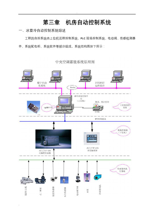
第三章机房自动控制系统一、冰蓄冷自动控制系统综述工程的自控系统由上位机远程控制系统、PLC现场控制系统、电动阀、传感检测器件、系统配电柜、系统软件等部分组成。
系统结构图如下所示:PLC控制软件为主的控制程序,该程序为美国西门子公司与CRYOGEL公司联合开发,已经在美国的多个工程中和台湾杰美利(GEMINI)得到应用,直接输入后调整。
上位机控制软件也可带采用CRYOGEL/(GEMINI)公司软件包的WinCC操作系统。
上位机远程控制设置先进的集中控制台,采用工控机配置打印机进行远程监控和打印,现场控制机采用PLC可编程控制器控制,进行系统控制、参数设置、数据显示,确保实现系统的参数化,实现系统的智能化运行。
本系统中的核心控制部分与机电执行装置采用国际著名品牌(西门子、江森、霍尼韦尔)的产品。
蓄能系统控制具体功能如下:⑴控制系统通过对主机、蓄热锅炉、蓄冰装置、板式换热器、泵、冷却塔、系统管路调节阀进行控制,调整蓄冷系统各应用工况的运行模式,在最经济的情况下给末端提供稳定的供水温度。
⑵根据季节和机组运行情况,自控系统具备所有工况的转换功能。
⑶控制、监测范围:a、制冷主机、泵、冷却塔启停、状态、故障报警;b、总供/回水管温度显示与控制;c、蓄冰装置及蓄热水箱进出口温度、显示与控制;d、蓄冰量、余冰量、乙二醇流量、瞬时释冷速度、蓄冷速度等标准规定参数的显示;e、电动阀开关、调节显示;f、备用水泵选择功能;g、各时段用电量及电费自动记录;h、空调冷负荷以及室外温湿度监测;i、可选的功能(包括楼宇智能化系统接口及接口转换程序)。
⑷控制系统对一重要的参数进行长时间记录保存,并将空调的实际运行日负荷通过报表或曲线图的方式记录,可以查询到某一段时间内的历史数据值,供使用者进行了解、分析,而且所有的监测数据可进行打印。
⑸控制系统配置灵活的手动/自动转换功能。
现场控制柜可手动控制所有设备的启停。
⑹可根据负荷变化情况调整运行策略,进行系统的优化控制,最大限度发挥蓄冷系统转移高峰负荷的能力,以最大限度节省运行费用。
PLC在中央空调中的应用 精品
()任务书专业班级姓名一、课题名称:PLC在中央空调中的应用二、主要技术指标:1.测量冷冻水供回水温度及流量2.各设备的程序联动:启动:冷却塔风机——冷却水泵——冷冻水泵——冷水机组。
停止:冷水机组——冷冻水泵——冷却水泵——冷却塔风机3.测量冷冻水系统供回水管的压差△P=P1-P2控制其旁通阀(TV)的开口度,使其维持压差。
三、工作内容和要求:1.PLC原理及应用2.PLC的选型及设置3.PLC控制系统主要功能与特点4.控制方法PLC原理及应用四、主要参考文献:[1] 吴继红、李佐周.中央空调工程设计与施工[M].高等教育出社[2] 张子慧等.制冷空调自动控制[M].科学出版社[3] 三菱公司.三菱微型可编程控制器编程手册[J][4] 顾战松、陈铁年.可编程控制器原理及应用[M].国防工业出版社.1996[5] 肖海亮.实现微机和PLC在以太网中的通信.20XX学生(签名)年月日指导教师(签名)年月日教研室主任(签名)年月日系主任(签名)年月日()开题报告设计(题目)PLC在中央空调中的应用一、选题的背景和意义:随着我国经济的不断发展,社会高度信息化,新的高科技技术不断应用到各个方面中,使得智能化已成为一种发展的必然趋势。
智能化也往往是从设备自动化系统开始。
本文主要针对我们本次的《智能化小型中央空调》阐述PLC控制设计与智能化中央空调(冷冻站)系统的关系。
二、课题研究的主要内容:1.PLC原理及应用2.PLC的选型及设置3.PLC控制系统主要功能与特点4.控制方法PLC原理及应用5.系统的设计和应用总结三、主要研究(设计)方法论述:1.通过各种教材论著归纳总结PLC的原理及应用方法2.通过华光电子工业有限公司的SU-5/B型。
主机:SU-5/B;输入模块:U -25N、U-01AD;输出模块:U-05T、U-01DA来测试PLC的性能3.通过智能化来应用PLC四、设计()进度安排:时间(迄止日期)工作内容8.1~8.3 选题8.4~8.5 完成开题报告8.6~8.8 看老师所给的一些资料,有一个基本的概念。
PLC在中央空调系统中的应用及故障检修
2019年1月CBZYJY 第7卷第1期PLC 在中央空调系统中的应用及故障检修收稿日期:2018-05-26作者简介:管旭(1977—),女,辽宁葫芦岛人,副教授,硕士,研究方向:电气控制。
DOI:10.16850/ki.21-1590/g4.2019.01.015中央空调由于其省电节能、美观舒适等优点,广泛应用于现代化大型建筑中。
PLC 以其节能减排、维护简单方便、性价比高等优点,已广泛应用于现代化自动控制系统中。
由PLC 结合变频技术控制的中央空调系统不仅降低了能源消耗,而且系统运行更加可靠、安全。
在使用过程中,用户只需设定好参数,空调就会根据负荷实际情况自动进行设备控制,达到人们预先设定的温度及湿度状态,由于此中央空调比传统中央空调系统有较大优势,因此PLC 控制中央空调已经成为现代空调的首选,逐渐走入千家万户。
1中央空调基本结构原理及PLC 控制特点在常见的建筑物中,中央空调制冷系统一般由冷却塔、冷水机组、冷却水泵、冷冻水泵、风机等主要设备组成。
[1]中央空调在工作中需要不断进行能量交换。
冷冻水在循环过程中,在吸收室内空气的热量升温后,再由冷冻泵将冷冻水送至冷冻主机,冷冻水在蒸发器中,吸热降温后,到达盘管或空调风机,在表冷器中吸收空气热量,形成闭合循环。
冷却水在循环过程中,经风扇散热后,由冷却泵将其送至冷冻机,经过冷凝器吸热升温后,经由冷却塔再到风扇,形成闭环循环系统。
[2]在高层摘要:PLC 以节能减排、维护简单方便、性价比高等优点,已广泛应用于现代化自动控制系统中。
由PLC 结合变频技术控制的中央空调系统不仅降低了能源消耗,而且系统运行更加可靠、安全。
在介绍中央空调基本结构原理及PLC 控制特点的基础上,阐述了PLC 控制中央空调节能原理,并对该系统常见故障检修知识进行了探讨。
关键词:PLC ;中央空调控制系统;故障分析与排除中图分类号:T P 273;T B 657.2文献标识码:A文章编号:2095-5928(2019)01-45-03(渤海船舶职业学院,辽宁兴城125105)管旭The Application and Troubleshooting of PLC in Central Air Conditioning SystemGUAN Xu(Bohai Shipbuilding Vocational College,Xingcheng 125105,China)Abstract:PLC has been widely used in modern automatic control system because of its advantages of energysaving and emission reduction,simple and convenient maintenance and high cost performance.The central air conditioning system controlled by PLC combined with frequency conversion technology not only reduces energy consumption,but also has more reliable and safe operation of the system.On the basis of introducing the basic structure principle of central air conditioning and the characteristics of PLC control,the paper explains the energy saving principle of PLC control central air conditioning,and probes into the common troubleshooting knowledge of the system.Key words:PLC;central air conditioning control system;fault analysis and troubleshooting船舶职业教育技术研究与应用452019年1月第7卷第1期及巨型建筑中,中央空调的控制和结构更为复杂,但基本原理相似。
PLC在中央空调系统中的应用
PLC在中央空调系统中的应用
禹海涛
【期刊名称】《科技创新与应用》
【年(卷),期】2014(000)013
【摘要】以写字楼的中央空调系统工程项目的设计为对象,设计了以PLC为核心的中央空调控制系统,实现了中央空调的自动控制。
基于当前中央空调行业冷水机组的技术不断趋于成熟为起点,对楼群制冷和制热方面进行分配和能源管理优化为目的,然后加以群控为手段来达到节能高效的目的。
【总页数】1页(P286-286)
【作者】禹海涛
【作者单位】青岛科技大学自动化与电子工程学院,山东青岛 266042
【正文语种】中文
【相关文献】
1.中央空调系统节能降耗改造中PLC与变频器的应用实践探讨
2.基于MODBUS TCP/IP网络的PLC行业应用LS(原LG)产电XGK PLC中央空调系统应用实例
3.PLC在冰蓄冷中央空调系统控制中的应用
4.PLC在中央空调系统控制中的应用
5.PLC在冰蓄冷中央空调系统控制中的应用
因版权原因,仅展示原文概要,查看原文内容请购买。
冰蓄冷中央空调系统
蓄冰槽容量: Qs=N2Cfqc=8×0.7×200=3920KwH
根据上式我们选用一台700KW双工况水冷螺杆机组,蓄冰槽的蓄冷量为3920kwH。
其冷冻站配置及概算如下:
内容
规格
数量 单位 功率 价格
合计
主机
24AUJ8H7
冷却塔 LBC-M-3-200
(KW)(万元) 功率(KW)总价(万元)
三、现以某工程为例来对蓄冷系统和冰蓄冷系统做一经济比较分析
某高层建筑总建筑面积15000m2,空调面积12000m2,建筑物总高度 54M为高一类工程。其功能主要以办公为主, 空调运行时间为8:00-18:00,消防水池的有效容积为600m3。
设计日全日最高负荷为:1232KW;设计日全日总冷量9854kwH,1、 水蓄冷系统:
蓄冷技术的原理,简而言之,是利用夜间电网多余的谷荷电力继 续运转制冷机制冷,并以冰(水)的形式储存起来,在白天用电高 峰时将冰融化提供空调服务,从而避免中央空调争用高峰电力,最 常用的蓄冷方式主要有两大类:冰蓄冷和水蓄冷。
共二十六页
一、冰蓄冷
冰蓄冷以冰为蓄冷介质,不同的制冰方式,构成不同的蓄冷系统。通常分完全 蓄冷与部分蓄冷。因为部分蓄冷方式可以削减空调制冷系统高峰耗电量,而且初投 资比较低所以目前采用较多,在确定部分负荷蓄冷系统的装置容量时,一般有两种 情况,
N2:夜间制冷主机在蓄冷工况下的运行小时数。 Cf:冷水机组系数(xìshù),即冷水机组蓄冰工况制冷能力与空调工况制冷能力的比值,一
般活塞式与离心式冷水机组约为0.65,螺杆式冷水机组约为0.7.它取决于工况的温度条件和机
组型号。
共二十六页
根据公式,结合具体工程,就可得出应配置的冷水机组的制冷能力与 蓄冰槽容量。
- 1、下载文档前请自行甄别文档内容的完整性,平台不提供额外的编辑、内容补充、找答案等附加服务。
- 2、"仅部分预览"的文档,不可在线预览部分如存在完整性等问题,可反馈申请退款(可完整预览的文档不适用该条件!)。
- 3、如文档侵犯您的权益,请联系客服反馈,我们会尽快为您处理(人工客服工作时间:9:00-18:30)。
PLC in the ice storage central air-conditioning system of control1 IntroductionIn PLC in 30 years which developed, it passes through develops unceasingly, already could unify simulates I/O, the network corresponds as well as uses new programming standard like IEC 61131-3. However, engineers only must use digital I/O and few simulations I/O number as well as simple programming skill on potential 80% industrial application.PLC has been widely used in all industrial sectors. According to "The United States market information" World PLC and software market report, in 1995 the global software PLC and its economies of scale of about 5 billion US dollars [5]. As electronic technology and the development of computer technology,Because uses traditional the tool to be possible to solve 80% industrial application, like this intensely needs to have low cost simple PLC; Thus promoted the low cost miniature PLC growth, it has the useful trapezoidal logical programming digital I/O. However, this has also created the discontinuity in the control technology, on the one hand 80% application need to use the simple low cost controller, but on the other hand other 20% application then have surpassed the function which the tradition control system can provide. Engineer is developing these 20% application to need to have the higher circulation speed, the senior control algorithm, the more simulations function as well as can well and the enterprise network integration.In 80 and the 90's, these must develop "20% application" engineers had considered uses PC in the industry control. PC provides the software function may carry out the senior task, provides the rich programming and the user environment, and the PC COTS part enables control engineer the technology which develops unceasingly to use in other applications. These technologies including floating point processor; High speed I/O main line, like PCI and ethernet; Fixed data memory; software development kit. Moreover PC also can provide the incomparable flexibility, highly effective software as well as senior low cost hardware.Ice thermal storage air conditioning is the central power grid could be redundant-night ice electricity in the form of cold storage, in the daytime peak hoursof electricity to provide air-conditioning services melting ice. As most parts of our country at night than during the day much lower price, using ice cold storage central air-conditioning can greatly reduce user operating costs.Ice storage central air-conditioning system configuration of equipment than conventional air conditioning system to increase some, require a higher degree of automation, but it automatically to meet the requirements of the air-conditioned buildings all day every day under the conditions of the energy he has exhausted all, the biggest limits to save operating costs.the PLC functions are greatly enhanced, with the following characteristics:(1) high reliability. PLC benefited from the high-reliability hardware and software on a series of anti-jamming measures and the cycle of its special scanning methods of work.(2) with rich I / O interface module. PLC for different industrial field signal and the corresponding I / O modules and industrial devices or equipment at the scene of a direct connection. In addition to improving performance, it also has a variety of man-machine dialogue interface modules to the industrial composition of local area networks, it also multiple communications network interface module.(3) modular structure. To meet the needs of various industrial control, in addition to a small PLC unit, the vast majority of PLC are modular structure. PLC various components, including the CPU, power supply, I / O, etc. is modular in design from the rack and cables will connect each module, the system's size and function in accordance with the needs of users of its own portfolio.(4) easy to learn programming. Most of the PLC programming relay control circuit similar to the ladder diagram form, the user, do not have computer expertise, it is easy to general engineering and technical personnel understand and master.(5) Installation is simple and easy maintenance. PLC does not require specialized equipment room in a variety of industrial environments can be directly run. Various modules are run and fault indication devices, user-friendly understanding of the operation and find fault. The modular structure, so any failure of a module, users can replace the module, allowing the system to rapidly resume operation.Second, the characteristics and Application of industrial PC2 control systemThe control system consists of the crew (Floor Control Workstation) and PC (central management workstation), with the crew using programmable logic controller (PLC) with the touch screen, PC using industrial-grade computers and printers, system configuration necessary if the annex communications equipment interfaces, network interface cards, modems and so on, to achieve the parameters of the storage system and intelligent automatic operation.Under the crew at the scene and touch-screen systems can control, parameter settings and data. PC remote management and print, it contains the crew and all of the features touch screen. Following the system as a whole crew of industrial programmable logic controller as the core, to achieve automatic control. Control equipment and devices including: detection sensor components, electric valves, converter, etc..Under the 2.1-Systems (Regional workstations)2.1.1 TP21 touch screenTP27 used as a color touch-screen operator panel, completely replace conventional button, lights device, the control cabinet interviewed more tidy. Moreover, TP27 touch screen at the scene showed that the state can be realized, system settings, mode selection, parameter setting, fault recording, record load, time-of-day, real-time data, load curve and reporting statistics, and other functions, Chinese intuitive and friendly user interface.2.1.2 SIEMENS PLCSIMATIC S7-300 Series PLC applied to all walks of life, all kinds of occasions in the detection, monitoring and control automation, its powerful features to both operate independently, or linked to a network able to achieve complex control functions.The product features photoelectric isolation, and high electromagnetic compatibility; high industrial applicability, allowing the ambient temperature of 60 ℃; has a strong anti-jamming and anti-vibration and impact resistance, in the harsh environment of the work has been widely applications.I also means freedom of communications S7-300 PLC, a very uniquefeatures, it makes S7-300 PLC with any communication protocol can open other equipment, communications controller, or PLC S7-300 can be defined by the users themselves communications protocols (for example ASCII protocol), baud rate of 1.5 Mbit / s (adjustable). Thus the scope of the communications can be greatly increased, the control system configuration more flexible and convenient. Any serial interface with peripherals, such as: printer or bar code readers, the drive, a modem (Modem), the upper PC can be connected to the machine. Users can program to develop communication protocol to exchange data (such as: ASCII character code), RS232 interface with the equipment available PC / PPI free cable linking communications communication.Chip and Chip Holderslntegrated Circuis are usually called Ics or chips. Thay are complex circuits, which have benn etched onto tiny chips of semiconductor(silicon). The chip is packaged in a plastic holder with pins spaced on a 0.1(2.54mm)grid, which will fit the holes on stipboard. Very fine wires inisde the package link the chip to the pins.1)Pin numbersThe pins are numbered anti-clockwise around the IC(chip) starting near the notch or dot. It shows the numbering for 8-pin and 14-pin Ics, but the principle is the same for all sizes.2)Chip holders(DIL sockets)ICs(chip)are easily damageded by heat when soldering and their short pins cannot be protected with a heat sink. Instead we use a chip holder, strictly calleda DIL socket(DIL=Dual In-Line), which can be safely soldered onto the circuitboard. The chip is pushed into the holder when all solding is complete.Chip holders are only nedded when solding so they are not used on breaboards.Commercially produced circuit boards often have chips soldered directly to the board without a chip holder ,usually this is done by a machine which is able to work very quickly .Please donnot attemp to do this yourself because you are likely to destory the chip and it will be different to remove without damage by de-soldering.3)Removing a chip from its holder4)If you need to remove a chip it can be gently prized out of the holderwith a small flat-blade screwdriver. Carefully lever up each end by inserting the screwdriver blade between the chip and its holder and gently twisting the screwdrive. Take care to statre lifting at both ends before you attempt to remove the chip,otherwise you will bend and possibly break the pins.5)Bipolar Integrated Circuits MOS Integrated CircuitsHistorically, bipolar Integrated Circuits used to be much more popular than MOS Integrated Circuits,particularly for small-sace logic Circuits. There were two major reasons for this: first, bipolar-junction transistors originally could be manufactured more reliably than MOS transistors,and second , they were faster, As the reliabitity of MOS transistors improved, and as integrated Circuits became more complex , which made the lower power and small size of MOS logic more important, the popularity of BJT logic decreased, however, BJT technology is still popular for the highest frequency logic circuits.When the PC offline, under the control of the next crew, the entire system can operate normally.PC System 2.2 (central management workstation)PC 2.2.1PC that is by control centre, mainly by the PC and laser printer components, SIMATIC WINCC software platform used by the entire Chinese user interface, friendly man-machine dialogue. Management and operation, can be observed by PC-display all kinds of information to understand the current and previous controlled the entire ice storage system and the operation of all parameters, and equipment through the mouse print management and the implementation of tasks.2.2.2 WINCC software platformWINCC software in the field of automation can be used for all operator control and monitoring tasks. Process control can be in the events clearly show, can show that the current state records in accordance with the order, all the recorded data can be displayed or select summary form, or may be required for editing, and output print statements and trends .WINCC able to control the process of the critical early stages of the report, and the signal can be displayed on the screen, and can also use voice demonstrated. It support the use of on-line help and operational guidelines to eliminate fault. WINCC a specialized workstations can be used to control the process so that the important process information is not shielded. - Aided software strategy assurance process is not illegal access, and provide for the industrial environment no wrong in the operation.WINCC is MICRSOFT WINDOWS98 or WINDOWS NT4.0 operating system, running on a PC object-oriented class 32 applications, through Windows OLE and ODBC standard mechanism, as an ideal communications partners to enter WINDOWS world, and therefore can be easily WINCC to integrate a company-wide data processing system.3 ice storage system control3.1 control objectives, scope and mainly controlled equipmentStorage Control System control purposes: Through the refrigeration host, ice storage devices, plate heat exchanger, the system pumps, cooling towers, piping system regulating valve control, ice storage system adjustment of the status of the operation mode, in the most economical circumstances to the terminal to provide a stable water supply temperature. At the same time, improve the level of automation, improve the management efficiency and reduce labor intensity management.Control of the ice storage system, including the entire state of the parameters, equipment status and control, the main control equipment: duplex status console, electric valves, cooling towers, cooling water pumps, ice storage devices, the primary glycol pump, plate heat exchanger , sub-glycol pumps.3.2 controlControl functions include the ice storage system stability, and economic operation of the required functions.3.2.1 status of the conversion functionDepending on the season and machinery operation, automatic control system with the following conditions conversion functions:A) duplex host ice conditions at the same time cooling mode; b) duplex status of a separate ice-making mainframe model; c) ice-storage devices and host jointcooling mode; d) of ice-melting separate cooling mode; e) for the console alone Cold model.3.2.2 The status of the start-up and shutdown, display and alarm functions FaultControl system according to the chronological layout with load forecasting software, mainframe and external control refrigeration equipment start-up and shutdown of the surveillance equipment and the number of working conditions and operating parameters, such as:-- Commitment refrigeration console, status and fault alarm - refrigeration mainframe operating parameters - the protection of water cooling host - host for refrigeration / return water temperature, pressure telemetry and display; - Commitment chilled water pumps, status and fault alarm -- glycol pump start-up and shutdown, status and fault alarm - start-up and shutdown cooling pumps, status and fault alarm - bypass pipe pressure measurement and display of pressure - the cooling tower fan Commitment, status and fault alarm;-- For the cooling tower / backwater temperature control and display; - for / return water temperature, pressure telemetry control and display - the import and export side of plate heat exchanger temperature control and display; - ice storage devices import and export control and telemetry temperature display; - chilled water backwater flow control and display; - electric valve switch valve position adjustment and control and display; - outdoor temperature and humidity control and telemetry showed - ice storage and display of measurement - the end of cold load control.3.2.3 Data recording and printing functionsControl system for the monitoring of the needs of the trends point to the entire record, the control system can be the load throughout the year (including the maximum daily load and the load throughout the day) and equipment uptime as tables and charts record for users . All monitoring points and the calculated data can be automatically print regularly.3.2.4 manual / automatic conversion functionFlexible control system configuration manual / automatic conversion function.3.2.5 optimized control functionAccording to outdoor temperature, weather, weather trends, the historical record, such as mainframe data automatically select the priority or ice-melting priority. In the end load to meet under the premise of the daily use of the cold storage End, as far as possible to run mainframe. Give full play to ice cold storage system advantages, saving operating costs.3.2.6 automatic functionalityFrom the PC system can work, in accordance with timetable for the automatic ice-making and control system operation, the conversion status of the system for automatic fault diagnosis, and remote alarm. Touch screen display systems operations, processes, each node parameters and operating records, the police records.3.2.7 holidays function setAccording to the timetable system can be run automatically, but also to pre-set holidays, and ice control certificates and certificates of ice time, the system does not require the holidays when the supply of cooling air-conditioned places to stop.3.2.8 operating under the crew functionLower-color touch-screen operator interface Figure 1.Under the crew operating functions are as follows:A) human-computer dialogue. Operation can be carried out through the touch panel interactive, user interface completely in the culture, with tips, help, parameter settings, key settings, fault enquiries, history and so on.B) system settings. Including operation password settings, run setup, operation of the timetable set record overflow processing, automatic / manual / test selection, holiday settings, the system parameter settings (including the junction temperature, pressure, the media flow, reservoir ice, ice rate, the ice-melting rate of valve opening, the terminal load.)C) fault records, running records, historical records.Remote Control 3.3Control system through the telephone line or broadband network, and expert system connectivity, the system operation control, parameter changes, such as dataacquisition, allowing the system to constantly improve and upgrade version of the software, allows users to get a better service. The purpose of the Remote Control users can PSTN (Public Switched Transport Network) on the remote frozen station at the remote monitoring. It may be remote debugging, remote monitoring and timely online maintenance, and so on, thus greatly mitigate the intensity of the work, lower cost of the project.3.4 control system expansionControl System Design friendly interface, PLC and touch screen can be extended, the content can be extended, parameters can be modified through the 485 communication interface or communications protocol BAS cold storage and ice-controlled system integration, savings investments, facilitate management. Centralized control system, reducing the dynamic counter area, and also allows the dynamic counter models reunification, the same style, same size. Extended control system are as follows:A) sewage pump control; b) wind, ventilation control; c) live pump regulator control; d) regular-pump operation, detection, alarm; e) leaching pump regulator control; f) construction of contour night lighting control ; g) measurement with low switching state detection, alarm.4 ConclusionPLC through ice storage air-conditioning systems in the promotion of the use of PLC verify the reliability of the system features to ensure the safe operation of the system and effective energy-saving, but also for building control equipment selection system controller provides a new way of thinking. I believe in the near future, a growing number of PLC systems in the ice storage air-conditioning systems in the use of the increasingly mature, in buildings and plant control systems will also play an active role.PLC在冰蓄冷中央空调系统控制中的应用1 引言在PLC被开发出来的三十年里,它经过不断地发展,已经能结合模拟I/O,网络通信以及采用新的编程标准如IEC 61131-3。