A STUDY OF SOLAR STREET LIGHT AND OPTIMIZATION FOR SPACING IN POLES
AGI32 Lighting Software AGI32 Tutorial 2 Roadway Optimizer
AGI32AAGI32AGI32 –Roadway Optimizer_Tutorial 2Purpose:AGI32Design Tool->RoadwayOptimizerAGI32IESNA 燈具分類:Type III Medium,CutoffPhotometric ToolAGI32建立自有的燈具庫建自有的具庫AGI32Input “AGI32 Tutorial 2” -> Add->CloseAGI32Step 1:點選AGI32 Tutorial 1-2燈具Step 2:將點選燈具加入選定的燈具庫內AGI32Using IESCalculation MethodMH 10m TA 10°MH=10 m,TA=10Road LayoutRW=24m,Lanes/Ro adway=6,Setback=05AGI320.5DefineConstraintAGI32Ranges are 5 to 50% above the desired value, and 0 to 50% below the desired value. For example: If the calculated average value is to be >=to the desired value set the ()range to 0%be >= to the desired value, set the (-) range to 0%This setting defines the maximum allowableThis setting defines the maximum allowable spacing in units of mounting height up to 30. Calculations stop when the spacing exceeds this value. For example: Maximum Allowable Spacing = 10 and Mounting Height =30 ft. The actual maximum allowable spacing = 10 x 30 = 300 ft ; minimum allowable spacing in units of mounting height down to 1. Calculations stop when the spacing falls below this value. For example: Minimum Allowable Spacing = 1 and Mounting Height =30 ft. The actual minimum allowable spacing = 1 x 30 = 30 ft.Determines the maximum number of iterations (up to 30) that Roadway Optimizerrounding to apply to the calculated spacing value. For example: A rounding of one results in possible spacing values of130,131,132,etc. A rounding value of 5 will yield spacing values of 130, 135, 140, etcAGI32min ill=15ave ill=35Step 1min. ill=15,ave. ill=35Step 1Step 2Step 3AGI32AGI32。
用系绳进行空间捕捉的最优控制研究

Key Words: tethered satellite; rendezvous opportunities; Gauss pseudospectral method; optimal control; capture’s trajectories.
II
南京航空航天大学硕士学位论文
插图目录
图 1-1 空间绳系捕捉系统简图 ............................................................................1 图 1-2 动量转移变轨示意图 ................................................................................2 图 1-3 二阶段方法的轨道变换示意图 ................................................................4 图 2-1 空间绳系捕捉系统的捕捉示意图 ..........................................................10 图 2-2 绳系飞行器捕捉系统示意图 .................................................................. 11 图 2-3 空间绳系系统的体坐标系 ......................................................................12 图 3-1 航天器的运行简图 ..................................................................................19 图 3-2 倾角为 0.5deg 的交会可行点示意图 .....................................................26 图 3-3 倾角为 1.0deg 的交会可行点示意图 .....................................................27 图 3-4 倾角为 1.5deg 的交会可行点示意图 .....................................................27 图 4-1 多段优化问题 ..........................................................................................29 图 4-2 直接方法与间接方法的求解过程 ..........................................................36 图 5-1 初始释放条件固定的状态量时间历程 ..................................................40 图 5-2 初始释放条件固定的控制力时间历程 ..................................................40 图 5-3 固定初始释放条件且轨道倾角为 0.5deg 的最优轨迹 .........................41 图 5-4 固定初始释放条件且轨道倾角为 1.0deg 的最优轨迹 .........................41 图 5-5 固定初始释放条件且轨道倾角为 1.5deg 的最优轨迹 .........................41 图 5-6 积分状态量与轨道倾角为 1.5deg 的状态量时间历程比较 .................43 图 5-7 优化初始释放条件的状态量时间历程 ..................................................44 图 5-8 优化初始释放条件的控制力时间历程 ..................................................44 图 5-9 优化初始释放条件且轨道倾角为 0.5deg 的最优轨迹 .........................45 图 5-10 优化初始释放条件且轨道倾角为 1.0deg 的最优轨迹 .......................45 图 5-11 优化初始释放条件且轨道倾角为 1.5deg 的最优轨迹........................45 图 5-12 含参数反馈的状态量时间历程 ............................................................48 图 5-13 含参数反馈的控制量时间历程 ............................................................48 图 5-14 含参数反馈且轨道倾角为 0.5deg 的最优轨迹 ...................................49 图 5-15 含参数反馈且轨道倾角为 1.0deg 的最优轨迹 ...................................49 图 5-16 含参数反馈且轨道倾角为 1.5deg 的最优轨迹 ...................................49 图 5-17 积分验证 ................................................................................................50
TOPCon太阳电池单面沉积Poly-Si的工艺研究
第53卷第5期2024年5月人㊀工㊀晶㊀体㊀学㊀报JOURNAL OF SYNTHETIC CRYSTALS Vol.53㊀No.5May,2024TOPCon 太阳电池单面沉积Poly-Si 的工艺研究代同光,谭㊀新,宋志成,郭永刚,袁雅静,倪玉凤,汪㊀梁(青海黄河上游水电开发有限责任公司西安太阳能电力分公司,西安㊀710100)摘要:目前隧穿氧化层钝化接触(TOPCon)电池制造技术越来越成熟,所耗成本不断降低㊂行业内普遍采用低压化学气相沉积(LPCVD)方式进行双面沉积或单面沉积㊂单面沉积存在Poly-Si 绕镀问题,严重影响电池片转化效率和外观质量,同时正面绕镀层去除难度较大,在用碱溶液去除绕镀层的同时,存在绕镀层去除不彻底或者非绕镀区域P +层被腐蚀的风险,导致P +发射极受损,严重影响电池片外观质量与性能㊂双面沉积可避免上述问题,但产能减少一半,制造成本增加㊂本文对单面沉积Poly-Si 工艺及绕镀层去除工艺进行研究,在TOPCon 电池正面及背面制作了一层合适厚度的氧化层掩膜,搭配合适的清洗工艺㊁去绕镀清洗工艺,既可有效地去除P +层绕镀的Poly-Si,也可很好地保护正面P +层及背面掺杂Poly-Si 层不受破坏,同时可大幅提升产能㊂关键词:TOPCon 太阳电池;Poly-Si 绕镀层;低压化学气相沉积;BSG;PSG;腐蚀速率中图分类号:TM914.4;TB43㊀㊀文献标志码:A ㊀㊀文章编号:1000-985X (2024)05-0818-06Single-Sided Deposition of Poly-Si in TOPCon Solar CellsDAI Tongguang ,TAN Xin ,SONG Zhicheng ,GUO Yonggang ,YUAN Yajing ,NI Yufeng ,WANG Liang (Xi an Solar Power Branch,QingHai Huanghe Hydropower Development Co.,Ltd.,Xi an 710100,China)Abstract :At present,the technology of tunnel oxide passivated contact (TOPCon)solar cells is becoming more and more mature,and the manufacturing cost is decreasing.TOPCon cell technology has been applied in the process of manufacture.Low-pressure chemical vapor deposition (LPCVD)is widely used in the industry for double-sided deposition or single-sided deposition.Single-sided deposition has the problem of Poly-Si winding coating,which seriously affects the efficiency and appearance quality of solar cells.It is difficult to remove the winding coating on the front side.While removing the winding coating in alkali solution,there is a risk of incomplete removal of the winding coating or corrosion risk of P +layer in non-winding plating area.As a result,the P +emitter is damaged,which seriously affects the appearance quality and performance of solar cells.Double-sided deposition can avoid the above risks,but the production capacity will be reduced by half,the manufacturing cost will increase.In this paper,the single-sided deposition of Poly-Si process and the removal process of the winding coating were studied.A layer of oxide coating with appropriate thickness is made on the front and back of TOPCon solar cells.With appropriate cleaning process and unwinding plating cleaning process,the Poly-Si winding coated with P +layer can be effectively removed,and the front P +layer and the doped Poly-Si layer on the back can be well protected from damage,and the production capacity can be greatly improved.Key words :TOPCon solar cell;Poly-Si winding coating;low pressure chemical vapor deposition;BSG;PSG;corrosion rate ㊀㊀收稿日期:2023-09-11㊀㊀作者简介:代同光(1986 ),男,山东省人,工程师㊂E-mail:tg334334@0㊀引㊀㊀言近年来,为应对能源危机和日益严重的环境问题,各国都在大力发展新能源,太阳能光伏发电技术因具有高效㊁清洁㊁取之不尽等优点,越来越受到国际能源产业的青睐㊂目前产业上应用最广泛的太阳能电池为传统晶硅电池,主要是以P 型单晶硅为衬底的钝化发射极背接触太阳电池(passivated emitterand rear cell,PERC)为主,但受P 型硅材料质量和器件结构设计的限制,其光电转化效率很难提高到23%以上[1]㊂而以N 型单晶硅片为衬底的N 型电池片,具有少子寿命高㊁对金属污染容忍度高㊁光致衰减低等㊀第5期代同光等:TOPCon太阳电池单面沉积Poly-Si的工艺研究819㊀优点,可用于制备双面电池,提高了太阳能电池系统的发电量,所以N型技术替代P型技术已成为光伏行业发展的趋势㊂在现有的N型电池中,隧穿氧化层钝化接触(tunnel oxide passivated contact,TOPCon)电池的隧穿氧化层和非晶硅层的沉积为硅片的背面提供了良好的表面钝化,提升了电池的开路电压和短路电流[2],TOPCon 电池具有工艺流程简单㊁效率提升空间大等优点,已被广泛应用于N型高效太阳能电池量产㊂TOPCon电池核心结构由SiO2隧穿氧化层和磷掺杂的多晶硅层组成,目前行业内TOPCon电池的制备方式主要为低压化学气相沉积(low pressure chemical vapor deposition,LPCVD)法[3]㊁等离子体增强化学气相沉积(plasma enhanced chemical vapor deposition,PECVD)法和溅射法,其中LPCVD技术制备的多晶硅膜层在片内及片间呈现较好的均匀性,电池端良率较高,工艺时间相对较短,生产效率高,同时LPCVD设备具有产能大㊁易于维护等优势,因此,LPCVD技术是目前TOPCon电池厂商布局的主流技术路线[4]㊂该技术采用LPCVD方式进行双面沉积或单面沉积,工艺的基本原理是将一种或数种气态物质,在较低压力下,用热能激活,使气态物质发生热分解或化学反应,沉积在衬底表面形成所需的薄膜㊂本征Poly-Si层的沉积主要应用硅烷的热分解来完成,在580~620ħ高温下,通入一定流量的硅烷,并将压力控制在一定范围内,硅烷热分解后在硅片表面沉积一定厚度的Poly-Si,化学反应式为SiH4ңSiˌ+2H2ʏ(1)其中单面沉积产能大但容易导致硅片正面边缘被绕镀Poly-Si(简称绕镀层),该绕镀层的存在影响电池正面对光的吸收,进而影响电池光电转换效率[5]㊂研究发现,与HF/HNO3酸刻蚀处理电池表面多晶硅绕镀相比,采用KOH碱刻蚀方法所处理的电池样品,在电池漏电流方面更具有优势[6],所以目前行业内普遍采用碱刻蚀去除绕镀层㊂但是碱溶液对前表面的腐蚀是全面的,也就导致前表面非绕镀区域也会受到影响,在去除绕镀层的同时,存在正面绕镀层去除不彻底或者非绕镀区域P+发射极被腐蚀的风险,严重影响电池片外观质量和性能㊂双面沉积可避免上述问题,但产能将减少一半,制造成本增加㊂为了保证单面沉积后电池的P+发射极在碱刻蚀过程中不被损坏,需要在P+发射极表面制备一层掩膜㊂本工作采用硼扩散时产生的硼硅玻璃(borosilicate glass,BSG)作为电池P+发射极掩膜,优点有:不增加新的生产设备,减少了电池制备成本;可通过调节硼扩散工艺实现P+发射极与BSG掩膜的共同制备,减少了电池制备流程,并避免样品转移过程带来的污染[6]㊂根据TOPCon电池工艺流程,在LPCVD后须对后表面进行磷掺杂㊂研究人员采用三氯氧磷热分解沉积方式进行磷掺杂,反应过程中生成的磷硅玻璃(phosphosilicon glass,PSG)被绕镀至硅片前表面,且绕镀的PSG厚度并不均匀,PSG的存在将影响Poly-Si绕镀层的去除,需要在去绕度工序前用HF 酸溶液去除㊂之前的研究人员通过实验发现,不同厚度的PSG叠加BSG,在HF酸溶液内的腐蚀速率不一致,进而影响前表面掩膜对P+发射极的保护作用㊂本文对单面沉积Poly-Si工艺及绕镀层去除工艺进行研究,通过在TOPCon电池正面及背面制备一层适宜厚度的氧化层掩膜,搭配刻蚀及去绕镀工序适宜浓度的清洗工艺,既可有效地去除P+层绕镀,也可很好地保护正面P+层及背面掺杂Poly-Si层不受破坏,解决Poly-Si绕镀层问题的同时,提高LPCVD产能㊂1㊀实㊀㊀验1.1㊀LPCVD单㊁双面Poly-Si沉积工艺对TOPCon电池外观及性能影响的实验在本公司TOPCon工艺产线其他工序工艺保持不变的条件下,LPCVD分别采用单插㊁双插方式制作电池,Poly-Si厚度120nm,对比LPCVD单㊁双面Poly-Si沉积时硅片前表面膜层结构的差异及LPCVD工艺后外观差异㊂1.2㊀LPCVD单㊁双面Poly-Si沉积时氧化层厚度对半成品外观影响的实验LPCVD采用单㊁双插方式制作电池半成品样片,在硼扩散㊁磷扩散工艺过程中,通过调整氧化压力,在硅片表面生长不同厚度的BSG㊁PSG,其他工序工艺保持不变,镀正面氮化硅后目测统计外观异常比例,实验设计如表1所示㊂820㊀研究论文人工晶体学报㊀㊀㊀㊀㊀㊀第53卷表1㊀不同氧化层厚度对单、双面Poly-Si 沉积TOPCon 太阳电池外观影响实验方案Table 1㊀Experimental scheme of effect of different oxide layer thickness on the appearance of single-sided anddouble-sided Poly-Si deposited TOPCon solar cellsLPCVDGroup Count Thickness of BSG /nm Thickness of PSG /nm G1-14008030Single-sideG1-240010040G1-340012050G2-14008030Double-side G2-240010040G2-3400120501.3㊀HF 酸溶液对不同厚度氧化层腐蚀速率影响的实验在上述实验硼扩散㊁磷扩散工艺过程中,同步使用碱抛光片在表面制备不同厚度的BSG㊁PSG㊁BSG +PSG,对比其在刻蚀HF 酸溶液内的腐蚀速率差异,实验设计如表2所示㊂表2㊀不同厚度氧化层在HF 酸内腐蚀速率实验方案Table 2㊀Experimental scheme of corrosion rate comparison in HF acid for different oxide layer thicknessOxide layer Thickness /nm Concentration of HF /%Time /s BSG 80 1.5120PSG 50 1.512080+30 1.5120BSG +PSG80+40 1.512080+50 1.51201.4㊀Poly-Si 厚度及绕镀面积对单面Poly-Si 沉积TOPCon 电池外观影响的实验LPCVD 采用双插方式制作电池半成品样片,通过调整LPCVD 沉积时间得到不同厚度的Poly-Si,其他工序工艺保持不变,镀膜后统计外观异常比例㊂1.5㊀实验过程实验材料:N 型金刚线切割硅片制绒后半成品若干㊁N 型金刚线切割硅片抛光片若干㊁HF 酸溶液㊂图1㊀TOPCon 电池制备工艺路径Fig.1㊀Preparation process path of TOPCon cells 实验设备及仪器:深圳捷佳创湿法槽式清洗设备㊁深圳捷佳创低压扩散设备㊁普乐LPCVD㊁RENA InOxSide 链式刻蚀机㊁深圳捷佳创管式镀膜设备㊁Syscos COSE PV4.0光谱椭偏仪㊂实验方法:取N 型金刚线切割硅片制绒后半成品若干,使用深圳捷佳创低压扩散设备进行硼扩散工艺,通过调整氧化压力制备不同厚度的BSG,硼扩后的样品按实验组进行分类,经RENA链式刻蚀机清洗背表面及侧边横截面的BSG 后,浸没在捷佳创湿法槽式设备NaOH 刻蚀槽中对背表面进行抛光,再使用普乐LPCVD 设备进行单㊁双面Poly-Si 沉积,之后在深圳捷佳创低压扩散设备进行磷扩散工艺,通过调整氧化压力制备不同厚度的PSG,后流转至去PSG 工序,使用RENA 链式刻蚀机清洗前表面绕镀Poly-Si 上层绕扩PSG,进一步在去绕镀清洗工序使用深圳捷佳创湿法槽式NaOH 刻蚀溶液去除绕镀Poly-Si,最后使用深圳捷佳创管式镀膜设备对硅片前表面镀氮化硅膜,实验结束后全检外观,统计半成品外观情况㊂上述硼扩散㊁磷扩散过程中,同步使用NaOH 碱刻蚀抛光后的硅片作为氧化层厚度监控片,并随样品进行流转,用于去PSG 工序监控氧化层厚度变化㊂实验样品制作工艺流程如图1所示㊂㊀第5期代同光等:TOPCon太阳电池单面沉积Poly-Si的工艺研究821㊀2㊀结果与讨论2.1㊀LPCVD单、双面Poly-Si沉积工艺对TOPCon电池结构及外观的影响当LPCVD采用双面沉积(单槽单插)时,硅片正表面㊁背面均沉积厚度一致的Poly-Si,硅片前表面颜色均匀㊂采用单面沉积(单槽双插)时,硅片背面沉积厚度一致的Poly-Si,硅片正面绕镀厚度不一致的Poly-Si,根据前表面外观颜色可以看出,从硅片边缘到中心,绕扩的多晶硅厚度呈递减趋势,单双面沉积P+层绕镀结构对比如图2所示㊂LPCVD工艺前和工艺后半成品前表面外观如图3所示㊂图2㊀LPCVD单面与双面结构图Fig.2㊀Structure of single-sided and double-sided by LPCVD图3㊀LPCVD单面与双面P+层外观Fig.3㊀P+layer appearance of single-sided and double-sided by LPCVD2.2㊀LPCVD单面Poly-Si沉积时氧化层厚度对半成品外观影响经实验数据分析(见表3)可知,LPCVD采用双面沉积时,样品镀膜后外观无异常㊂LPCVD采用单面沉积时,当硼扩散BSG厚度小于80nm时,在BOE去绕镀时不足以保护P+层,导致部分区域被腐蚀抛光;当BSG厚度大于100nm时,抛光现象消除;当PSG厚度大于40nm时,在BOE去绕镀时P+层局部被过度腐蚀导致外观发白的比例最高;当PSG厚度小于40nm时,发白比例随PSG厚度减小而递减㊂外观正常及异常图片如图4所示㊂表3㊀LPCVD单面与双面匹配不同厚度氧化层的外观数据Table3㊀Appearance data of single-sided and double-sided by LPCVD matching with different oxide layer thickness LPCVD Group Proportion of polishing/%Proportion of whiten/%G1-110 Single-side G1-200.5G1-30 1.5G2-100 Double-side G2-200G2-3002.3㊀HF酸溶液对不同掺杂氧化层腐蚀速率的影响HF酸对不同厚度氧化层腐蚀能力数据如图5所示㊂从图中可以看出,不同氧化层在同一浓度HF酸溶液内的腐蚀速率为:V BSG<V PSG<V BSG+PSG㊂在腐蚀BSG+PSG叠层掩膜时,随着PSG厚度的增加,腐蚀速率将增大,而在磷扩工艺过程中,P+层绕镀的PSG厚度是不一致的,这将导致刻蚀在去除P+层PSG绕镀时,腐822㊀研究论文人工晶体学报㊀㊀㊀㊀㊀㊀第53卷蚀速率不一致,部分区域剩余掩膜较薄,在去绕镀时被腐蚀,被腐蚀区域比表面积变小,在镀氮化硅膜时,同一条件下,反应气体流量相同,比表面积大的区域沉积的氮化硅厚度越小,而比表面积小的区域则反之[7],导致被腐蚀区域膜厚异常,外观呈发白状,所以在选择磷扩散工艺时,要尽量降低P +层绕扩的PSG 厚度,以降低BSG +PSG 叠层掩膜在刻蚀的腐蚀速率差异㊂图4㊀LPCVD 单面经去绕镀㊁镀膜后的外观Fig.4㊀Appearance after dewinding and coating of single-side by LPCVD图5㊀HF 酸对不同厚度氧化层腐蚀能力数据Fig.5㊀Etching ability data of HF acid to different oxide layers thickness 2.4㊀改进效果评估综上所述,通过在TOPCon 电池前表面制备适宜厚度的BSG 掩膜,同时控制PSG 厚度,可有效解决单面Poly-Si 沉积导致的外观异常,同步制作两组改进前和改进后的电池片进行对比,统计前表面外观异常比例和电性能参数,评估改进效果,实验条件及结果如表4所示㊂实验结果显示,改进前外观抛光比例1.2%,外观发白比例1.8%,改进后外观无明显异常㊂改进前外观异常区域PN 结被腐蚀破坏,难以产生光生伏特效应,导致转化效率损失,改进后外观无异常,电池性能显著提升㊂表4㊀不同厚度氧化绕镀层对单面Poly-Si 沉积TOPCon 太阳电池外观及电性能影响Table 4㊀Effects of different oxide layer thickness on the appearance and electrical properties of TOPCon solar cells deposited by single-sided Poly-SiGroup Count Thickness of BSG /nm Thickness of PSG /nm U oc /V I sc /AR s /ΩR sh /ΩFF /%NCell /%Proportion of polishing /%Proportion of whiten /%Baseline 40080500.706513.69140.0009460282.6624.27 1.2 1.8Improvement 400100300.707413.69950.0008466582.7824.32003㊀结㊀㊀论1)在TOPCon 工艺过程中,LPCVD 采用单面Poly-Si 沉积时,前表面非绕镀区域在清洗去绕镀时容易被腐蚀,导致电池片外观异常㊁效率损失㊂㊀第5期代同光等:TOPCon太阳电池单面沉积Poly-Si的工艺研究823㊀2)氧化层厚度对TOPCon电池外观起着至关重要的作用,当硼扩散BSG厚度小于一定量时,在BOE去绕镀时不足以保护P+层,导致部分区域被腐蚀抛光;PSG厚度大于一定厚度时,在BOE去绕镀时P+层局部易被过度腐蚀导致发白㊂3)各掺杂氧化层在刻蚀HF酸溶液内的腐蚀速率为:V BSG<V PSG<V BSG+PSG㊂在腐蚀BSG+PSG叠层掩膜时,随着PSG厚度的增加,腐蚀速率将增大㊂4)通过在TOPCon电池正面制备一层适宜厚度的氧化层掩膜,搭配刻蚀及去绕镀工序化学品1.5%浓度的清洗工艺,即可有效地去除P+层绕镀的Poly-Si,也可很好地保护正面P+层不受破坏,解决单面沉积Poly-Si 外观异常的同时,提高LPCVD产能㊂参考文献[1]㊀张㊀志.隧穿氧化层钝化接触(TOPCon)太阳电池的研究[D].昆明:昆明理工大学,2019.ZHANG Z.Research on tunneling oxide passivation contact(TOPCon)solar cells[D].Kunming:Kunming University of Science and Technology,2019(in Chinese).[2]㊀肖友鹏,李桂金.硅太阳电池钝化载流子选择性接触概念与现状[J].电源技术,2019,43(11):1897-1900.XIAO Y P,LI G J.Concept and present situation of passive carrier selective exposure in silicon solar cells[J].Chinese Journal of Power Sources,2019,43(11):1897-1900(in Chinese).[3]㊀SACHS E,PRUEGER G,GUERRIERI R.An equipment model for polysilicon LPCVD[J].IEEE Transactions on SemiconductorManufacturing,1992,5(1):3-13.[4]㊀王举亮,贾永军.LPCVD法制备TOPCon太阳能电池工艺研究[J].人工晶体学报,2023,52(1):149-154.WANG J L,JIA Y J.Preparation of TOPCon solar cells by LPCVD method[J].Journal of Synthetic Crystals,2023,52(1):149-154(in Chinese).[5]㊀张㊀婷,刘大伟,宋志成,等.多晶硅绕镀层的去除工艺研究[J].人工晶体学报,2020,49(9):1641-1645.ZHANG T,LIU D W,SONG Z C,et al.Research on surround coating removal technology for polysilicon[J].Journal of Synthetic Crystals, 2020,49(9):1641-1645(in Chinese).[6]㊀周㊀颖.n型隧穿氧化层钝化接触太阳电池的量产关键问题研究[D].大连:大连理工大学,2021.ZHOU Y.Study on key Issues in mass production of N-type tunneling oxide passivation contact solar cells[D].Dalian:Dalian University of Technology,2021(in Chinese).[7]㊀涂宏波,马㊀超,王学林,等.晶硅太阳电池氮化硅膜产生色差的影响因素研究[J].化工中间体,2013,10(5):37-41.TU H B,MA C,WANG X L,et al.The inluence factors causing color diference of silicon nitride film of crystalline silicon solar cell[J].Chemical Intermediates,2013,10(5):37-41(in Chinese).。
路灯安置问题的优化
f] h rG n e.用 M pe和 MA l B解决 科 3Wa e adr al 下J A 为确定点 x的数值 ,对各参数进行赋值 , 学计 算 问题 [ . 京 : 京 燕 山 出版社 .04 M/ 北 北 20 . 塑 O x=一 + 9 9 【) 8 参 数 值见 表 1 。 对各参数赋值后 , 利用 mal pe软件绘制 出 令式 ( ) 8 等于零 , 得到 x的一个有效的最优 总 照 明强 度 函 数 Cx曲 线 , 灯 A ( ) 路 B各 自的 照 明强度函数S() 和 。 曲线及 总照明强度的 照 明点 的横 坐 标 : ㈨ 导函数 d c 曲线 。见图 2 C= ) 。 由图 2 知 , 照 明强 度 的 导 函数 d=C( 可 总 C ) + 的零点的区间(, ) 求出在这区间内最小照明 5O。 l 得: 量 又 由丝 强度的点 X(.3 3O , 93 8 ,)且最小照明强度 C n mi O x3 O x x x
=
3 结 论
由 s ,≥ , 于i n + X
、意 ^, f t, , s 十一
导, 得
O C
一
基 于 以 上 的计 算 ,对有 关 照 明 问题 给 出 下
路灯 A B各 自的照明强度 函数 S( 和 s()于 I) , x x 是得到点 x 的总照明强度 Cx: (1
引 言 现 阶段 , 国大 多 数 城 市 的 景 观 照 明对 该 我
类 空 问 的研 究 、 规划 和设 计 开始 逐 渐 受 到重 视 , 然而更多的是倾向于照明设计 的艺术性 ,而对
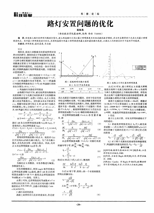
于怎样 合理安置路灯的高度和路灯的强度 以达 到 既 满 足 需 要 又 节 约 能 源 的 问题 却 不太 关 注 。 将路灯照明问题 简化 ,讨论 的是一条水平 的道 路上同侧两盏路灯的照明强度问题。问题剖面 示意图如图 l 。 其中 , ——路灯的亮度 =I ) 灯 ,, 2h 的高度 ( 1) 一 光线的投射角度 =1) ,, 2 ,, 2 S s ——A B两盏路灯的水平距 离。x ——两盏路 图 1道 路 照 明 问题 示 意 图 灯 间 最 低照 明强 度 的点 (,) B两盏 路灯 的 的 0 A  ̄ 表 1式() 2 中各 参数 值 坐标分别为: , , ,2。 ( 啊)( h 0 ) 1两 盏 路 灯 间最 低 照 明强 度 由物理学知识 可知, 被光线照射 的物体 的 亮度依赖于它与光源之间的距离平方 的倒数和 光线的投射角度l l l 。由图 1 可看出 , 从点 x到光 用 点光 源 是 不 能解 决 问 题 的 。而 对 于 给定 亮 度 源 A 的水 平距 离为 x ,到 光 源 B的水 平 距 离 为 和 给定 间 隔 的光 源 ,可 以通 过 调 整 光 源 的 高度 因此 , 道路照明问 s x 根据勾股定理可得点 x到 AB两个光源之 来使最小照明强度达到最大 。 ~。 间的距离 r和 r分别为 = + = O 曲 。 题并 不 是 一 维 函数 ,而是 有 三 个 变量 的三 维 函 。 2 砰 , + 一 数 C x|, (,l I )。最低照明强度的点 x仍是 由总 l 从A B两盏灯到点 X的光线强度 Ix和 Ix: 。) 2) ( ( 照 明强度函数 C x啊, 梯度的根来确定的。 (, ) 1x 1 ( h 2+ x2,1 2 .( 南 x 对总照明强度函数 Cx ) 变 量 求 偏 (, , 各
路灯模型

路灯照明
30. 关于 h2 极大化 E(x) 给定 h1, 对于每个 h2 都存在一个最小照明点 xm(h2) 求 h2*使得在其最小照明点xm(h2*)处照度最高. 即
E ( x m ( h )) max E ( x m ( h 2 ))
* 2
E x 3 P1 h1 x (h
20. 最低照明点
dE dx dE 1 dx dE 2 dx 3 P1 h1 x (h x )
2 1 2 5/2
3 P2 h 2 ( s x ) (h (s x) )
2 2 2 5/2
0
令 P1=2000W,P2=3000W,h1=5m,h2=6m, s=20m. 可求得 x =(0.028, 9.34,19.98) E =(81.98,18.24,84.48) xe = 9.00
路灯照明
计算 E x 0 , 可以得到
h2
*
E h1 0 ,
E h2 0
P2[( s - xm)2 - 2h2*2] = 0 和 P1(xm2 – 2h1*2)=0
tan 2 s xm
*
2 2
tan 1
h1
*
2 2
xm
1 2 35 . 26
路灯照明
照度定律:点光源 O 与被照明平面中心 A 的距 离为 h 时,平面上 A 点的照度 E= (I / h2) cos a, 其中,I 为 O 点的光强度,a 为平面的法线方向与 光源到 A点连线之间的夹角。
路灯照明
基于数学建模的城市路灯优化与节能研究
1 路 灯 的 优 化 建模
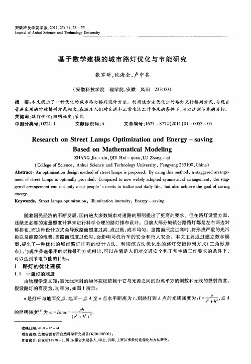
1 1 一 盏灯 的照度 .
由物理 学定 义知 : 被光 线 照射 的物体亮 度依赖 于它 与光 源之 间的距离 平方 的倒数 和光线 的投 射角 度 。 假设 路灯 的高度 为 , 功率 为 , 图 1 示 : 如 所 o 灯杆 与地 面交点 , 面 一点 A至 。点 水平 距离 为 r则路 灯到 A点 的光 线 强度 为 : = 是 地 , ,
Re e r h o t e tLa p tm i a i n a d En r y — s v n s a c n S r e m s Op i z to n e g — a i g Ba e n M a h m a ia o ei g sd o te tc lM d l n
5 4
安 徽 科 技学 院学 报
照明强度 直接影 响可 见度 , 只有照 明强 度不低 于 c , 。 才可 认 为物体 可见 , 因此地 面照 明强度不 低 于 c 。 的区域为 :。 — c
( + ‘ h)
, rs( ) h 此时 , 即 }一 在达 到 最低 照 明强度 的条 件下 , 得地 面上 可见 区域 使
Z A G J xn Q U H i q a ,U Z o g— i H N i i , I a — u n L h n q a—
( o eeo c n e A h i c n ea dT c nlg nvri , ega g 3 10, hn ) C l g f i c , n u i c n eh o yU i sy F ny n 30 C ia l Se Se o e t 2
安 徽 科 技 学 院 学 报 ,0 12 ( ) 5 5 2 1 ,5 1 :3~ 5
太阳光压作用下空间太阳能电站的动力学响应
太阳光压作用下空间太阳能电站的动力学响应徐方暖;邓子辰;王博;魏乙;李庆军【摘要】研究了太阳光压作用下绳系空间太阳能电站的姿态和结构振动动力学响应.将太阳能电池板简化为Euler-Bernoulli梁,平台看作质点,绳子看作无质量的弹簧,建立了绳系空间太阳能电站的简化模型.采用绝对节点坐标法将梁离散,通过Hamilton 原理建立了系统的动力学方程.采用辛Runge-Kutta方法进行数值仿真,通过数值算例验证了新模型和数值方法的有效性.最后,数值仿真表明,结构振动和太阳光压均会使系统的姿态产生小幅度振荡,太阳光压对结构振动产生的影响可忽略不计.%The attitude and structural vibration of tethered solar power satellite were studied considering solar radia-tion pressure. Firstly, the simplified model of tethered solar power satellite was established. The solar panel was modeled as an Euler-Bernoulli Beam, the bus was modeled as a particle, and the tethers were modeled as massless springs. The equations of motion were derived based on absolute nodal coordinate formulation and Hamilton's princi-ple. Then, Symplectic Runge-Kutta method was adopted to solve the differential equations. The proposed model and numerical algorithm were validated through a numerical example. Finally, numerical simulations were carried out. Simulation results showed that solar radiation pressure as well as structural vibration cause small fluctuation of the attitude angle. Moreover, the effect of solar radiation pressure on structural vibration can be neglected.【期刊名称】《西北工业大学学报》【年(卷),期】2018(036)003【总页数】7页(P590-596)【关键词】空间太阳能电站;太阳光压;绝对节点坐标法;辛算法;Hamilton系统;空间系绳;弹性变形【作者】徐方暖;邓子辰;王博;魏乙;李庆军【作者单位】西北工业大学工程力学系,陕西西安 710072;西北工业大学工程力学系,陕西西安 710072;钱学森空间技术实验室,北京 100094;西北工业大学应用数学系,陕西西安 710072;西北工业大学工程力学系,陕西西安 710072【正文语种】中文【中图分类】V19空间的太阳能能量密度比地面高,且不受昼夜、季节、天气等影响[1-2],因而空间太阳能电站自提出以来受到了美国国家航空航天局、美国能源部的高度重视,第一个提出空间太阳能电站的概念:1979 SPS基准系统[3]。
响应曲面法优化MIL-100(Fe)光催化降解三氯卡班
第37卷第2期 齐 齐 哈 尔 大 学 学 报(自然科学版) Vol.37,No.2 2021年3月 Journal of Qiqihar University(Natural Science Edition) March,2021响应曲面法优化MIL-100(Fe)光催化降解三氯卡班刘梦雪,高立娣*,秦世丽,刘旭(齐齐哈尔大学 化学与化学工程学院,黑龙江 齐齐哈尔 161006)摘要:采用自制的金属有机框架MIL-100(Fe)为光催化剂,以三氯卡班的降解率为响应因子,应用响应曲面法(RSM)对影响TCC降解率的主要因素进行了优化,建立了MIL-100(Fe)光催化降解TCC的二次多项式模型。
获得最佳光降解条件为:TCC初始浓度为1.00mg/L,H2O2浓度为0.10mmol/L,pH值为13;三氯卡班光降解率的实验值与预测值具有良好的一致性,相对误差仅为1.06%。
该研究为有效去除环境中的三氯卡班提供了基础数据和理论参考。
关键词:响应曲面法;三氯卡班;光催化降解;MIL-100(Fe)中图分类号:O643.36;O644.1 文献标志码:A 文章编号:1007-984X(2021)02-0055-05三氯卡班(TCC)是一种被广泛使用的高效广谱抗菌剂,也是近年来水体中主要存在的一种新兴有机污染物。
TCC在我国五大水系中均有检出,对人类健康和生态环境存在潜在的危害[1-2]。
因此,如何有效地去除水环境中的TCC是亟待解决的问题[3]。
光催化降解有机污染物具有价廉、节能、高效的优点,常见的光催化剂有TiO2、ZnO、CdS等多种金属化合物[4-5],但多数光催化剂易产生水体的二次污染。
而MIL-100(Fe)[6]作为一种铁基金属有机框架(MOFs)材料,将其作为环境污染物的光降解催化剂,除具有较大的比表面积、可选择的孔道、较高的光能利用率和转化率外,铁源对水体的二次污染也极小。
可见,将MIL-100(Fe)用于水环境中污染物的去除具有潜在的实际应用价值[7-8]。
溴到硼酸酯
Materials Chemistry C
Published on 20 November 2014. Downloaded on 08/12/2016 07:54:22.
PAPER
View Article Online
View Journal | View Issue
Cite this: J. Mater. Chem. C, 2015, 3, 861
However, these oligouorene functionalized oligomers may suffer from the unwanted long wavelength emission under long-term device operation, similar to polyuorene-based macromolecules.34–36
Received 26th September 2014 Accepted 17th November 2014 DOI: 10.1039/c4tc02173h /MaterialsC
Starburst 4,40,400-tris(carbazol-9-yl)triphenylamine-based deep-blue fluorescent emitters with tunable oligophenyl length for solution-processed undoped organic lightemitting diodes†
Introduction
Since 1987, organic light-emitting diodes (OLEDs) have attracted tremendous attention due to their potential applications in at-panel displays and solid-state lightings.1–10 To achieve fullcolor displays, three primary RGB luminescent materials with excellent stability, efficiency and color purity are required. With respect to green and red counterparts, it seems to be a big challenge to develop blue emitters, especially deep-blue ones that have a Commission Internationale de l'Eclairage (CIE) y coordinate value of <0.10, because the intrinsic wide bandgap would inevitably result in inefficient charge injection to an emitting layer (EML).11 Therefore, great efforts should be paid to the design of deep-blue emitters to push forward the commercialization of full-color OLEDs.
美国ASHTTO规范
LRFDUS-4-E3
7/30/2007
AASHTO LRFD Bridge Design Specifications
Customary U.S. Units 4th Edition 2007
American Association of State Highway a n d Tr a n s p o r t a t i o n O f f i c i a l s
7/30/2007
Section 8: Wood Structures pp. 8-13–8-34 Article 8.4.1.2.3 Article 8.4.1.3 Article 8.4.4.4 Article 8.4.4.4 Article 8.5.2.4.3 Insert Tables 8.4.1.2.3-1 and 8.4.1.2.3-2 In the title for Table 8.4.1.3-1, change “Base Resistance and Modulus of Elasticity” to “Reference Design Values” Relocate Tables 8.4.4.4-1 and Table 8.4.4.4-2 to the end of Article 8.4.4.4 Delete Table 8.4.4.4-1, Deck Factors, Cp, for Mechanically Laminated Solid Sawn Lumber Decks Change article header “8.5.2.4.3 Stability” to “8.5.2.3 Stability” Section 11: Abutments, Piers, and Walls pp. 11-3/11-4 Article 11.3.1 Article 11.3.1 Article 11.3.1 Article 11.3.1 pp. 11-9/11-10 pp. 11-13/11-14 pp. 11-15/11-16 pp. 11-19/11-20 pp. 11-31/11-32 pp. 11-79/11-80 Article 11.5.6 Article 11.6.2.1 Article 11.6.3.1 Article 11.6.4 Article 11.9.4.3 Article C11.10.11 For PH, change “(11.10.11.1)” to “(11.10.10.1)” For Pv, change “(11.10.11.1)” to “(11.10.10.1)” For P′v, change “(11.10.11.1)” to “(11.10.10.1)” For ΔsH, change “(11.10.11.2)” to “(11.10.10.2)” In paragraphs 1 and 2, change “Tables 10.5.5-1 through 10.5.5-3” to “Tables 10.5.5.2.2-1, 10.5.5.2.3-1, 10.5.5.2.4-1,” Change “Articles 10.6.2.2.3, 10.7.2.3, 10.2.2.3,” to “Articles 10.6.2.4, 106.2.5, 10.7.2.3 through 10.7.2.5, 10.8.2.2 through 10.8.2.4,” Change “Article 10.6.2.2.4” to “Article 10.6.2.5” Change “Article 10.6.3.1.5” to “Article 10.6.1.3” Change “Articles 11.6.3.6, 11.6.3.7,” to “Articles 11.6.3.5, 11.6.3.6,” In paragraph 2, change “Article C10.6.2.2” to “Article C10.5.2.2” Section 12: Buried Structures and Tunnel Liners pp. 12-1/12-2 pp. 12-5/12-6 pp. 12-79/12-80 pp. 12-83/12-84 Article 12.3 Article 12.3 Article 12.3 Article 12.3 Article 12.13.3.3 Article 12.14.5.8 For Bd, change “Article 12.10.2.1.2” to “Article 12.11.2.2” For Cd, change “Article 12.10.2.1.2” to “Article 12.11.2.2” For γs, change “Article 12.9.2.2” to “Article C12.9.2” For μ′, change “μ′ ” to “μ” [no prime] and “(12.10.2.1.2)” to “(12.10.2.1)” Change “Article 12.3.2.2” to “Article 12.13.2.2” Change “Article 5.10.8.2” to “Article 5.10.8” Section 14: Joints and Bearings pp. 14-27/14-28 pp. 14-41/14-42 Article 14.5.6.9.7a Article 14.7.1.2 In paragraph 1, change “Article 6.10.7.4.2” to “Article 6.10.10.2” Change “Table 6.4.1-2” to “Table 6.4.2-1”
- 1、下载文档前请自行甄别文档内容的完整性,平台不提供额外的编辑、内容补充、找答案等附加服务。
- 2、"仅部分预览"的文档,不可在线预览部分如存在完整性等问题,可反馈申请退款(可完整预览的文档不适用该条件!)。
- 3、如文档侵犯您的权益,请联系客服反馈,我们会尽快为您处理(人工客服工作时间:9:00-18:30)。
A STUDY OF SOLAR STREET LIGHT AND OPTIMIZATION FOR SPACING IN POLESAND COST1ABHINANDAN SHARMA, 2Prof. (Dr.) B. K. SHARMA, 3HARI SINGH, 4BHANU PRATAP SINGH1Scholar, Suresh Gyan Vihar University, Jaipur, Email: abhinandan.sharma000@2Prof & Head, MEd, Dean Students Welfare, Email: bks.sharmaaa@ 3Assistant Professor, Department of Mechanical Engineering, GVSET, Jaipur, Email: harisingh027@ 4Scholar, Suresh Gyan Vihar University, Jaipur, Email: pratap.bhanu755@ABSTRACTIn this paper we are studding the convectional led light of renewable energy of electrification. Now the India has been using the remote control of energy in solar power. Solar electrification is the most important part of the developing in India as it is urban area or rural area. In this paper, we are focusing the optimization of solar electrification to charge of power, cost efficient and efficiency effect. Also discuss the how LED light is more efficiently as compare to the CFL light in solar street light. We will discuss the study of LED light and CFL light about access the energy in solar project. Solar street light project has developed by new technology as automated control system, tubular battery, panel’s type. India is using the solar street light in rural areas because of the less transportation of electricity in rural areas. We are studding the rural street light in Rajasthan to generate the solar electric light in road. Solar Street light is friendly behavior of human being to save the energy and reduces the criminal cases on road in night and also reduced the accident in night. Street light optimization is discussing the sufficient of street light in an area of road in INDIA.We are discussing the population of rural area and use the street light to evaluate the effect on environment by the different type of light.KEY WORDS: Solar street light, rural development, Renewable energy, Energy conservation, Distance optimization.1.INTRODUCTIONTheoretical workThe research of light has been crucial in solar power system. It is work on sun light to photovoltaic cells. The natural lights which come from sun rays is absorbed by the solar photovoltaic and create the energy into the electric energy. Electric energy is stored in batteries and flow the current in CFL or led light. Now these days, the improvement of the research in electricity by the sun rays is the more efficiently and less light pollution. In present day, we are using the CFL and Led light in street light system. CFL and LED light has less maintenance cost, but the led light has high installation charge. But the maximum efficiency of the LED light is good by its given luminance and a better illumination comparison to CFL light.Fig. 1‐ Sun rays on solar panel The source of light sun which provides the illuminationis conducting the semi conductor material. The solar panels are the device which converts the light energy to the electric energy. Mono‐crystalline and Polycrystalline are the basic type of solar panel. Mono‐crystalline has more efficiency as compare to Polycrystalline. Mono‐crystalline panel has some demerit it stops when the any part of crystalline in shadow.Table 1: Solar electrification in rural area in mwSource: MNRE, 2011_17.Solar energy convert of electric energy is stored in battery in power which gives the current of light bulbs. Battery is supported to load of the invertors to carry the control of charge the battery. We use the tubular battery in the solar system to reduce the resistance in battery and the wires. Solar heat to electricity is no convectional recourses. Solar panel are fixed in series and in parallel, each cells are made on silicon to increase the current. The crystalline silicon as like ribbon and thin silicon are most popular in solar system. Led light are based on silicon carbide and it is less emitted diode. In rural areas are using the led much better than other lamp. Led save not also power but also money standard all other current and consume the 50% power saving. Led has the good white brightness and it’s available in large production. Cause of much appliance it’s shipping in large amount of production for the consumer. Solar power system has take place the fossil fuel in some area as well as home power, street light, industries etc. Renewable energy has adoption the some type of power like water power, wind turbine, tidal power, and solar technologies.Table2: Electricity generation in IndiaSource: MNRE report, 2011_17.Solar trackers are the work in the clean sky and track the sun rays for the good output. It tracks the one and two axis the sun rays. When tracker is track the sun rays it passes the one axis east to west throughout the whole day and the module of cells and the light do not change it direction it always fix on its angle. Controller is the device which controls the dc electricity and command to the device which control the electric gear machine to generate the electricity. It is used for the collecting on sun rays by the solar panel.Fig.2‐ The block diagram of the solar street lightsystem (IJESRT) The rural area has developed the using the solar electrification and willingness to pay the charge of electricity. Solar electrification has less bill charge and less use of fossil fuel, great brightness of light. Street light turn off and on automatically by the sensors. In winter season when sun does not arise it can maintain automatically. Now the available of latest technology of street light we found the new types of installation of street light like wireless technology, fuzzy method. Street light has neither pollutants nor rotating parts and no moving parts causes of this government approved the authorized of street energy to research of solar projects.Fig 3‐ Energy consumption in countriesIn India has become the major problems of the supply of fuel and it is also going to be misbalanced to supply the energy. India is importing the 80% of fuel in couple of year so it is becoming the major roll of problem in security of energy. The uses of large amount of energy in electricity has needed the new generation of production of electrification. The demand of light in industry, institute and residence is increasing the value of thermal plants in using fuels and the demand. The rural areas where the lack of electricity is using the more amount of kerosene. This is all decreasing the value of subsidies of government and increasing dependence the important of fuel.Fig.4 ‐ % in energy consumptionThe renewable of energy has supporting in area of energy in residential, industrial, commercial and rural area. The renewable energy has less effect of environment. Government has approved the power ofthe energy resources in the basic plans and change to theministry of using of the renewable energy in large amount. The renewable energy is using the grid/off‐grid distribution of light in resources in the rural areas. The vision of the government to use of next generation of electricity has prepared the affects of the atmosphere in local area, national and worldwide energy consumption. To calculation of development, decreasing, the total use and the going to be use of energy are measuring by the scientific, numerically and the technical equations solution now available.Table3: Efficiency of solar panelThe important principal of street light has become the requirement of safety, security, environmental issue and the cost effectiveness of the road lights. Te government takes place in rural area and urban area to use the street light by the help of solar renewable resources. This is the awareness of the accident which is harmful for the human being and pedestrianism of the road side in rural areas for drivers. It has created the main roll of stop the criminal activities on road. When we design the any type of light we must consider the round of the area like residential, commercial, street light and the industrial. Different area wants the different type of design in street light as it airport or road way street light. The changing of vision of light has become the growth of the rural street light or urban street light. There are many segment types of situation of read as it is single road then the one side road electrification and the double road in the double side road electrification. The strategy of the road is depend of the road as it is single or double. The distribution of light is calculated of the distance and height in short size, medium size and high side of the strategy of road.Fig.5‐ Intensity vs. distance (1/cm2) Rajasthan has the big area of India’s map and the deserts have the large ball of this state. Rajasthan has parted with 33 districts, 244 Tehsils, 249 panchayat and 184 urban cities. The area of lighting in Rajasthan has forward in urban states and the rural states. Rajasthan are using the non convectional of solar resources of solar photovoltaic products in street light. Now the Rajasthan is using the solar products in street light, historical buildings, residential areas, commercial areas and the industrial areas where the electric light is being more costly. This type of solar street light has possible to good achievement to result of energy cost, consumption and the maintenance. And the color of light is choosing by the selection of area.2.OBJECTIVE AND MATERIAL2.1 ObjectiveThe objectives of solar street light are using optimization of cost in the rural area of India with LED light. The calculation of LED and CFL light in street light are servicing with efficient and less of cost use. The major objectives of solar street light have promoted the reducing of fossil fuels and increase the using of new technology of renewable energy sources. The mobilization of financial report of rural areas has implemented in renewable energy sources and generating of electricity by the renewable energy.The electricity is using in the rural areas increase continuous day by day so the developing of energy resources by appreciate the demand and need of them street light system. To increase the energy efficiency and avoid the other generating energy sources. The focus of renewable energy has developing of the village street lighting system.The further use of solar street light system has removed the many problems of the rural area like that crime rate, increase the community of people at work etc. The solar street light system has no pollution like other power generation plant and it is non‐convectional system to less space and efficient electricity output.2.2 Problem definitionThe rural areas have no solar street light system, the rural areas of people has difficulties of late night working. The rural area is far from the main cities so supply of electricity is not possible to every village. The resources of electricity are also less than the demand which is increasing continuous every year. This research focus on sustainable development in rural areas through solar street lights this research focuses on the latest eco‐friendly technology and its suitable use for rural development.Problem assumption∙To keep the various parameter in street light to installation in the rural area in India.∙To optimize the cost of the solar street light and distance between the two pole.∙To optimum area of the installation of street light in villages of India.∙To calculation of the battery and panel in using of street light by according of the use of light (CFL & LED).∙To show the effect of the emission of pollution and heat effect on the environment.∙To doing the economy and good payback period of the solar street light.Problem limitation∙9 watt, 18 watt, 15 watt and 30 watt light use in the solar street CFL and LED light.∙Take the energy efficiency of solar panel in 14% efficiency of the available in India.∙12 volt battery in the nominal voltage and tubular battery use in the street light installation system.∙ G. I. pole in the nominal height in 4m and 5m with the 2 core 2.5 segment wire.∙ Polycrystalline solar panel is used in the 12 volt and 250 C temperatures.3.MATERIAL AND METHODS3.1 Solar cell working principle:Solar panel is the device which converts the solar energy to the electric energy by the help of semiconductor. Solar panel has made of thin silicon plate. This silicon plate is working in the mono‐crystalline and the polycrystalline. Solar panels are connected to the series and parallel when they fix in series and parallel it called module. Solar cell module produced the DC electricity according to the STC (Standard Test Condition). Solar cell efficiency depends upon the module by given area for its output. Solar cell produced the limited electricity for the single function. There are many types of power wants the multiple modules for multiple outputs.Fig 6‐ solar cell 74 wattSolar cell module plates are made on crystalline cell (wafer based) and the thin film cell (cadmium telluride and silicon). Solar cell module can take load on the top of the plate and back of the plate and it has the safety protection based on the mechanical and moisture for its damaging problem. Solar module’s structure has rigid body and the thin film plate solar module are flexible available in the market also. We can find the easily solar module according to its desired voltage or current. Solar panel module use the connection of the MC3 and MC4 are available easily with the weatherproof and the free from the moisture.Fig 7 specification of solar cellSolar panel modules are the fix on the fixed rack above the pole and fixed across the sun. Now the solar module can be recycle and the produced the power throughout the end of life.3.2 MaterialsSilicon is the most admired material for solar panel it is semiconductor material and with the evolution of nanotechnology efficiency of solar panel get increase. Doping is done in silicon cell to increase the efficiency of solar panel.Different material through which solar cell is made are: SiliconAmorphous Silicon (A‐Si)gallium arsenide(GA As)cadmium telluride (CdTe)Copper indium Diselenide (CIS).3.3 Types of solar panelThere are three types of solar panel which are following:1.Polycrystalline solar panel2.Mono‐crystalline solar panel3.Hybrid solar panelFig.8‐ solar panel 20 wattFig.9‐ Technical specification of 20 watt solar panel 3.3.1Polycrystalline solar panelPolycrystalline solar panel is also called the Poly‐silicon. The material of polycrystalline is use of small silicon crystals which are different from the single crystalline silicon. Polycrystalline material has contained the small crystals of silicon. Polycrystalline is made of 99% pure silicon.3.3.2 Mono‐crystalline solar panelMono‐crystalline solar panel is the single crystal panel which is based on the industry composition. Mono‐crystalline solar panel is made of the single crystalline on the entire of solid plate continuously. Mono‐crystalline solar panel is more efficient to the polycrystalline but behavior of the work polycrystalline is much better than the mono‐crystalline.3.3.3Hybrid solar panelHybrid solar panel is the made of both combinations organic and inorganic. These organic and inorganic structure is worked in hybrid for the donor and acceptable. The organic structure donates the power and it is made of conjugate polymer materials. The inorganic structures are accepting the power in form of electricity. Hybrid solar panel is the latest technology in the industries for providing the better efficiency to other solar products. Hybrid solar system is not only the purpose of solar collecting but also it scales the power of panel collecting.Table 4: Solar panel rupees per wattSource: Market cost per wattEfficiency TableTable 5: Showing solar cell efficiency for differentmaterialSources: MNRE report, 2011_17.3.4 CFL LIGHTCFL (compact fluorescent light) is made for the interchange of the incandescent light. It is more capable and efficient to the incandescent light. According to the power saving, compact fluorescent lamp takes the one third or one fifth part of power save compared to the incandescent light. Compact fluorescent lamp takes the eight times extra in compared to the incandescent lamp also. Incandescent lamp is less leverage cost then the compact fluorescent light but the compact fluorescent light has the extra lifetime and less electric bill then he incandescent light.Types of compact fluorescent lightCompact fluorescent light are two types:1.Integrated compact fluorescent lamp2.Non‐integrated compact fluorescent lamp3.5 Integrated compact fluorescent lamp Integrated compact fluorescent lamp is the mixing of light tube and bed in the single unit. Compact fluorescent lamp has available in the market and reduced the price of electric bill more than the incandescent lamp. Integrated compact fluorescent lamps are available in the market in form of 3‐way light tube.3.6 Non‐integrated fluorescent lampNon‐integrated compact fluorescent lamp has the permanently installed the ballast in the form of lumens and light bulb tube depended to end of life of the bulb. Non‐integrated lamp is the greater than the integrated light. It has larger size of tube to the show the betterluminaries.Table 6: CFL required cost of battery with volt andAHIt has fix of ballast in internal of the fixture. Non‐integrated lamp does not replace the light bulb. Non‐integrated lamps have not good efficiency in compared to the integrated lamp and it is costly.CFL light are using in the street light projects. CFL light has replaced the incandescent lamp in street light area causing the saving of the energy and the control the resisting of power of the battery.CFL keep the adjustment of the power of street light on the basis of battery backup. Many countries have used the CFL in street light at the urban and rural area. Fluorescent tube is also used in street light. CFL light has removed the high pressure mercury lamp and use the slow light wattage bulb and accomplish to 20‐25% electric saving.Table 7: CFL in average lumen in watt per day3.7 Calculation of CFL for lifeTotal life of CFL = 6000 hoursCFL will glow 10 hour in a daySo no of days are 6000/10= 600 daysTo convert into year 600/ 365= 1.6 yearTable 8: CFL life in hour and years3.8 Light emitting diode (LED Light)Light emitted diode is the light source in the integrated light. Light emitted diode has the fixture and ballast in the same circuit. Light emitting diode has emitted the light because of the activation of resembling in the PN‐junction and two lead semiconductors. Led light has made of 1mm2 area bulbs in a series.Led light has discovered in normally 5mm and T1/4, but it is more powerful in brightness of light. Blue and white light has made on the vital different crystal segments of nucleon but the causes of the high brightness and high efficiency it has replaced the CFL, Incandescent lamp and fluorescent lamp.Table 9: LED light average lumen in watt per day3.8.1 Type of led lightThere are four types of led light.1.Miniature led light2.Mid‐range led light3.High power led light4.Ac driven led light1.Miniature led lightMiniature led light mount of the single die led which used in the indicator. The manufacturing of the miniature led light is 2mm to 8mm and in the distinctive current.2. Mid‐range led lightMid‐range led light is use in the behavior of holes and produced of barely o/p of lumens of light. Mid‐range led light wants the four diodes two anode and two cathode diode become a suitable heat acquit.3. High power led lightHigh power led light is need of the more than 100mA and current.4. Ac driven led lightAc driven led light works on the ac current it does not need the dc current. Air conditioner light needs the ac driven light. Ac driven light control in the ac circuit and the very simple circuit for driven the ac driven led light.3.8.2 Application of led lightThe applications of led light are following:1.Ac driven led light are widely use in traffic signalsand the automobile indicators.2.Street light for rural and urban area.3.To communication the data and other signalresources.4.In basic light and other lighting resources.5.For saving the energy utilization.6.To show the data in machineries.7.In electronic contact lens.3.8.3 Calculation of led for lifeTotal life of led = 20,000 hous (syska led life = 60,000 ) LED will glow 10 hour in a daySo no of days are 20,000/10= 2000 daysTo convert into year 2,000/365= 5.5 yearTable 10: Led life in hour and year3.9 Control systemAutomated control system is using the street light to switching ON and OFF instead of work manually. The organization of energy has worked on the street light to generate the automatic control system. They have not worked other area in street light but choose the system to make effective and efficiencies. So, they have developed the automatic control system in street light. To changes of economic problems dynamic, using the national and international of modernization has prepared the supply cost of energy, effectiveness become the major roll of the street light. Then need to be the quite acceptable function in street light. As like to consideration of traffic problems and reducing the energy consumption is changing the value of street light. The reduction of operational cost in automated system has made the main function of solar street light. It does not affect the any emission in environment.Fig.10‐ Reading of panel in ecosence solar meter Automated control system in sensors which works measured responsible to the changes in physical condition like the temperature and thermal conductivity. Microcontroller is the device which analyzed the data inputs by the IR and light dependent resistance. The microcontroller street light automated system is not only the up and down system but it is made a valuable product in market. Automated street light has become the efficient valuable energy saving in the every area on streets like traffic lights, street light, communication, and the solar resources. The outcome of the automated street light has major result of the market and expected to grow up the outcome result will increase dramatically with the new generation of street light.3.10 BatteryBattery is an electric cell or a device which convert the chemical energy into the electrical energy. Battery is the device which connected to the two or more cells in the series and the parallel. Battery is also the power of single cell. Each cells are consist the liquid, gas and solid electrolyte to connect the positive electrode and the negative electrode. Battery is working as the electrodes in form of power then the electrons are work throughout the cells and the electric current flow in the system. The positive electrode is work on the cathode rod and the negative electrode work on the anode rod.3.10.1 Types of batteryThere are two types of battery:1.Primary battery2.Secondary battery3.10.1.1 Primary batteryPrimary battery or single cell battery are used as the irreversible cells once electrode materials during the discharged. The alkaline batteries are use in the portable device. Primary battery does not charge after the discharge of any system.3.10.1.2 Secondary batterySecondary battery is performing as the reversible battery. Secondary battery can be discharge and the charge as it current at the multiple times. The composition of the anode and cathode can be restoring the current. The secondary batteries are like the lead‐acid battery which is using the many areas like the vehicles, wrist watches, computers and the solar power projects. The worldwide battery companies has generated the more efficiently battery in the market. Batteries have more specified fuel used like the gasoline. Battery has the voltaic cells who converts the directly the chemical energy to the electrical energy.3.10.1.3 CalculationWe are discussing about the calculation of street light in luminaries of LED and CFL bulbs. The calculation of solar panel has defended to the watt per uses in street light and how is it effective. Solar Street light is the friendly technology to produce the efficient energy in rural areasin Rajasthan. In this research, we are finding the using ofstreet light by the calculation and cost effect on electric bills. If we calculate the theoretically values of the battery, volts, solar panel and flow of current then we take the following calculation:Calculation for 15 watt luminaryLuminary = 15 wattBattery used for this solar street light system = 12 V Watt hour = 15 × 20= 300 Wh(15watt luminary and 2 day autonomy = 20hours)Total load in milliamp‐hour (mAh) = (watt hour × 1000) /volts (V).2= (300 × 1000) /12= (300,000) /12= 25,000 mAh= 25,000 /1000(1 Ampere =1000 Milliamps)= 50 Ah (Ampere‐hour)Efficiency of sealed tubular battery is 80 % so 80 % of 50 = 40 AhAfter consideration of losses battery required is 62 Ah Battery required for 15 watt luminary is 12 V and 62Ah. Charging current required for 12 V and 62Ah = 10 % of its Ah.= 10/100 × 62= 6.2 Ampere (A)Solar charge controller must be of 12 v and 6.2 ampereTheoretical watt required to charge the battery ( )Solar panel required for 12 V and 62Ah battery = Volts × charging current= 12 × 6.2= 74 wattPractical watt required to charge the battery ( ) Total losses =15%0f 74 = 11 wattPractical watt = theoretical + loss= 74 + 11= 85 watt Solar panel of 85 watt with charging current of 6.2 Ampere is required.Table11‐Luminary battery costTable12‐ Battery, charging current and solar panelrequired for luminaryFig 11‐ Battery, charging current and solar panelrequired for luminaryTable 13: CFL light in expensive (Rs.)Fig.12‐ CFL light in expensive (Rs.)Table 14: LUX with pole heightCalculation of spacing of street light for 9 watt LED lightCalculation of space of two street light poles having the fixed wattage is 9 watt. The luminaries of street light 819 lm. For the sufficient road which has width of 12 foot in rural areas.Lux (E) = 10 luxCoefficient of Utilization Factor (Cu) = 5.3Light lumen depreciation factor (LLD) =.8Luminaries dirt depreciation factor (LDD) = .9For distance between two street light = LM*CU*LLD*LDD/E*W= 1000*5.3*.8*.9/10*12= 3816/120= 32 ft. [1 meter = 3.2 ft]The distance between two streets light is 10 meterTable15: Distance b/w poleFig.13‐ Distance b/w pole in solar street light poleCalculation for cost of solar panel by considering the lossesAs no system is 100 % efficient and each component of the system have certain due to which efficiency of system get decrease, economy of the system get increase. solar street light system also have losses associate with each component .we generally study losses in battery, panel and in wire .Our calculation is done by taking necessary losses for practical economical of our solar street light .The efficiency of solar cell is 35 % in India, the power output of solar panel as per watt follows:20 watt solar panel cost 12v poly generated electricity = 55 w/p (Rs.)= 1500(Rs.)50 watt solar panel cost 12v poly generated electricity = 55 w/p(Rs.)= 2750(Rs.)74 watt solar panel cost 12v poly generated electricity =75 w/p(Rs.)= 4070(Rs.)100 watt solar panel cost 12v poly generated electricity = 75 w/p= 5500(Rs.)Table16: Cost of panel。